JP4681249B2 - Disk array device - Google Patents
Disk array device Download PDFInfo
- Publication number
- JP4681249B2 JP4681249B2 JP2004116115A JP2004116115A JP4681249B2 JP 4681249 B2 JP4681249 B2 JP 4681249B2 JP 2004116115 A JP2004116115 A JP 2004116115A JP 2004116115 A JP2004116115 A JP 2004116115A JP 4681249 B2 JP4681249 B2 JP 4681249B2
- Authority
- JP
- Japan
- Prior art keywords
- data
- logical volume
- disk
- virtual
- amount
- Prior art date
- Legal status (The legal status is an assumption and is not a legal conclusion. Google has not performed a legal analysis and makes no representation as to the accuracy of the status listed.)
- Expired - Fee Related
Links
Images


Classifications
-
- G—PHYSICS
- G06—COMPUTING; CALCULATING OR COUNTING
- G06F—ELECTRIC DIGITAL DATA PROCESSING
- G06F3/00—Input arrangements for transferring data to be processed into a form capable of being handled by the computer; Output arrangements for transferring data from processing unit to output unit, e.g. interface arrangements
- G06F3/06—Digital input from, or digital output to, record carriers, e.g. RAID, emulated record carriers or networked record carriers
- G06F3/0601—Interfaces specially adapted for storage systems
- G06F3/0628—Interfaces specially adapted for storage systems making use of a particular technique
- G06F3/0646—Horizontal data movement in storage systems, i.e. moving data in between storage devices or systems
- G06F3/065—Replication mechanisms
-
- G—PHYSICS
- G06—COMPUTING; CALCULATING OR COUNTING
- G06F—ELECTRIC DIGITAL DATA PROCESSING
- G06F11/00—Error detection; Error correction; Monitoring
- G06F11/07—Responding to the occurrence of a fault, e.g. fault tolerance
- G06F11/14—Error detection or correction of the data by redundancy in operation
- G06F11/1402—Saving, restoring, recovering or retrying
- G06F11/1415—Saving, restoring, recovering or retrying at system level
- G06F11/1435—Saving, restoring, recovering or retrying at system level using file system or storage system metadata
-
- G—PHYSICS
- G06—COMPUTING; CALCULATING OR COUNTING
- G06F—ELECTRIC DIGITAL DATA PROCESSING
- G06F11/00—Error detection; Error correction; Monitoring
- G06F11/07—Responding to the occurrence of a fault, e.g. fault tolerance
- G06F11/14—Error detection or correction of the data by redundancy in operation
- G06F11/1402—Saving, restoring, recovering or retrying
- G06F11/1446—Point-in-time backing up or restoration of persistent data
- G06F11/1448—Management of the data involved in backup or backup restore
-
- G—PHYSICS
- G06—COMPUTING; CALCULATING OR COUNTING
- G06F—ELECTRIC DIGITAL DATA PROCESSING
- G06F3/00—Input arrangements for transferring data to be processed into a form capable of being handled by the computer; Output arrangements for transferring data from processing unit to output unit, e.g. interface arrangements
- G06F3/06—Digital input from, or digital output to, record carriers, e.g. RAID, emulated record carriers or networked record carriers
- G06F3/0601—Interfaces specially adapted for storage systems
- G06F3/0602—Interfaces specially adapted for storage systems specifically adapted to achieve a particular effect
- G06F3/0614—Improving the reliability of storage systems
-
- G—PHYSICS
- G06—COMPUTING; CALCULATING OR COUNTING
- G06F—ELECTRIC DIGITAL DATA PROCESSING
- G06F3/00—Input arrangements for transferring data to be processed into a form capable of being handled by the computer; Output arrangements for transferring data from processing unit to output unit, e.g. interface arrangements
- G06F3/06—Digital input from, or digital output to, record carriers, e.g. RAID, emulated record carriers or networked record carriers
- G06F3/0601—Interfaces specially adapted for storage systems
- G06F3/0628—Interfaces specially adapted for storage systems making use of a particular technique
- G06F3/0646—Horizontal data movement in storage systems, i.e. moving data in between storage devices or systems
- G06F3/0652—Erasing, e.g. deleting, data cleaning, moving of data to a wastebasket
-
- G—PHYSICS
- G06—COMPUTING; CALCULATING OR COUNTING
- G06F—ELECTRIC DIGITAL DATA PROCESSING
- G06F3/00—Input arrangements for transferring data to be processed into a form capable of being handled by the computer; Output arrangements for transferring data from processing unit to output unit, e.g. interface arrangements
- G06F3/06—Digital input from, or digital output to, record carriers, e.g. RAID, emulated record carriers or networked record carriers
- G06F3/0601—Interfaces specially adapted for storage systems
- G06F3/0668—Interfaces specially adapted for storage systems adopting a particular infrastructure
- G06F3/0671—In-line storage system
- G06F3/0683—Plurality of storage devices
- G06F3/0689—Disk arrays, e.g. RAID, JBOD
-
- G—PHYSICS
- G06—COMPUTING; CALCULATING OR COUNTING
- G06F—ELECTRIC DIGITAL DATA PROCESSING
- G06F2201/00—Indexing scheme relating to error detection, to error correction, and to monitoring
- G06F2201/84—Using snapshots, i.e. a logical point-in-time copy of the data
-
- G—PHYSICS
- G06—COMPUTING; CALCULATING OR COUNTING
- G06F—ELECTRIC DIGITAL DATA PROCESSING
- G06F3/00—Input arrangements for transferring data to be processed into a form capable of being handled by the computer; Output arrangements for transferring data from processing unit to output unit, e.g. interface arrangements
- G06F3/06—Digital input from, or digital output to, record carriers, e.g. RAID, emulated record carriers or networked record carriers
- G06F3/0601—Interfaces specially adapted for storage systems
- G06F3/0628—Interfaces specially adapted for storage systems making use of a particular technique
- G06F3/0653—Monitoring storage devices or systems
Description
本発明は、ディスクアレイ装置に関し、特にスナップショットにおける差分LUの管理技術に関する。 The present invention relates to a disk array device, and more particularly to a management technique for differential LU in a snapshot.
コンピュータシステムにおいては、ストレージ装置に記憶されるデータをバックアップする場合など、元のデータを記憶した記憶ボリュームの複製を生成する場合がある、この場合、元のデータを記憶した記憶ボリュームと複製データを記憶した記憶ボリュームとは内容が一致し整合性が保たれる必要がある。そのためには複製の生成が完了するまでの間、元のデータを記憶した記憶ボリュームの更新を停止させる必要がある。しかし高可用性が求められるコンピュータシステムなどでは、元のデータを記憶した記憶ボリュームに対するアクセスを停止することができない場合がある。 In a computer system, there may be a case where a copy of a storage volume that stores the original data is generated, such as when data stored in the storage device is backed up. In this case, the storage volume that stores the original data and the copy data are generated. The stored storage volume must have the same content and be consistent. For this purpose, it is necessary to stop updating the storage volume storing the original data until the generation of the replica is completed. However, in a computer system or the like that requires high availability, access to the storage volume that stores the original data may not be stopped.
そこで、元のデータを記憶した記憶ボリュームと複製データを記憶した記憶ボリュームとの間である時点での整合性を保ち、ある時点の後に元のデータが更新されたとしてもある時点の元のデータを参照できるようにするスナップショットと呼ばれる技術が開発されている。 Therefore, the consistency between the storage volume storing the original data and the storage volume storing the replicated data is maintained at a certain point in time, and even if the original data is updated after a certain point, the original data at a certain point A technique called “snapshot” has been developed so that it can be referred to.
スナップショットの技術によれば、整合性を保つべき時点の後に元のデータが更新される場合には、整合性を保つべき時点のデータを別の記憶ボリュームに記憶するようにする。つまり元のデータは、更新されなければそのままであり、更新される場合には整合性を保つべき時点のデータが別の記憶ボリュームに記憶される(例えば、特許文献1参照。)。 According to the snapshot technique, when the original data is updated after the time point at which consistency is to be maintained, the data at the time point at which consistency is to be maintained is stored in another storage volume. That is, if the original data is not updated, the original data remains as it is, and if updated, the data at the time when consistency should be maintained is stored in another storage volume (see, for example, Patent Document 1).
また、スナップショットを複数世代において利用可能にする方法が提案されている。 In addition, a method for making snapshots available in multiple generations has been proposed.
これによれば、データ保持部1は、通常の読み書きを行う。データ保持部2は、ある時点でのデータ保持部1のスナップショットイメージを保存する。データ保持部3は、データ保持部2にスナップショットイメージを保存した時点以降のデータ保持部1へのデータ書替えに伴う更新データと、その世代を示す情報と、その更新領域を示す情報とを含む履歴情報を保存する。データ読出し元選択部4は、読出されるべきスナップショットイメージの世代及び領域の指定に応じて、データ保持部3に保存される各履歴情報を参照し、読出されるべきスナップショットイメージの保存場所を知得し、その保存場所に応じてデータの読出し元をデータ保持部2及びデータ保持部3のいずれかに切替える(例えば、特許文献2参照。)。
しかし、スナップショット機能は、正LUの容量よりも差分LUの容量を減らせることが利点であるが、ホストからのデータの書き込みが多くなると差分データが多くなる。そして、プール領域(差分LU)の使用量が100%になるとスナップショットを維持できなくなる。このため、プール領域の使用量が閾値を超えたときに、管理者に警告を発する。この警告を受け取った管理者は、データを別ディスクへ退避して、プール領域の使用量を減らす、又はV-VOLを削除する等によって、運用で処理されていた。そのため、管理者の負担が大きく、プール領域の使用量が100%になることの回避に失敗するリスクを抱えていた。 However, the snapshot function is advantageous in that the capacity of the differential LU can be reduced compared to the capacity of the primary LU, but the amount of differential data increases as the number of data writes from the host increases. When the usage amount of the pool area (difference LU) reaches 100%, the snapshot cannot be maintained. For this reason, a warning is issued to the administrator when the usage amount of the pool area exceeds the threshold value. The administrator who received this warning was processed in operation by saving the data to another disk to reduce the pool area usage or deleting the V-VOL. For this reason, the burden on the administrator is large, and there is a risk of failure to avoid the pool area usage amount becoming 100%.
本発明は、プール領域の使用量が100%になることを回避して、全スナップショットイメージの破壊を防止することを目的とする。 An object of the present invention is to prevent destruction of all snapshot images by avoiding the usage amount of a pool area from becoming 100%.
本発明は、上位装置に接続され、前記上位装置からデータを受ける上位インタフェースと、データが格納される複数のディスク装置と、前記上位装置との間でやり取りされるデータの前記ディスク装置への読み書きを制御する複数のディスクインタフェースと、前記複数のディスクドライブの記憶領域を用いて生成される第1の論理ボリュームへのデータの読み書きを制御し、前記第1の論理ボリュームに格納された過去のデータを世代毎の差分データとして第2の論理ボリュームに書き込むように制御し、前記第2の論理ボリュームに格納されている前記世代毎の差分データの関係を管理するスナップショット管理テーブルを前記メモリの領域に設けることによって前記差分データを管理する制御プロセッサと、を有するディスクアレイ装置であって、前記制御プロセッサは、前記第2の論理ボリュームに格納されたデータ量を管理し、前記第2の論理ボリュームに格納されたデータ量が前記第2の論理ボリュームの容量の第1の割合を超えた場合、前記第2の論理ボリュームの容量を増加し、前記第2の論理ボリュームに格納されたデータ量が、前記第1の割合より大きい第2の割合を超えた場合、前記第1の論理ボリュームに対するデータの書き込みを制限し、前記第2の論理ボリュームに格納されたデータ量が、前記第2の割合より大きい第3の割合を超えた場合、前記第2の論理ボリュームに書き込まれた差分データのうち、特定の世代の差分データを削除し、前記第2の論理ボリュームに格納されたデータ量が、前記第3の割合より大きい第4の割合を超えた場合、前記第2の論理ボリュームに書き込まれた差分データのうち、前記特定の第1の論理ボリュームに対応するものを削除すること特徴とする。 The present invention relates to a host interface that is connected to a host device and receives data from the host device, a plurality of disk devices that store data, and reading and writing of data exchanged between the host devices to the disk device Past data stored in the first logical volume by controlling the reading and writing of data to the first logical volume generated using the plurality of disk interfaces for controlling the storage area and the storage areas of the plurality of disk drives Is written in the second logical volume as difference data for each generation, and a snapshot management table for managing the relationship of the difference data for each generation stored in the second logical volume is stored in the memory area. disk array instrumentation and a control processor for managing the differential data by providing a A is, the control processor, the second manages the stored data amount in the logical volume, the data amount stored in the second logical volume is a first volume of the second logical volume When the ratio is exceeded, the capacity of the second logical volume is increased, and when the amount of data stored in the second logical volume exceeds a second ratio that is greater than the first ratio, When data write to one logical volume is restricted and the amount of data stored in the second logical volume exceeds a third ratio that is greater than the second ratio, the data is written to the second logical volume. If the difference data of a specific generation is deleted from the difference data and the amount of data stored in the second logical volume exceeds a fourth ratio that is greater than the third ratio, Of the difference data written to the second logical volume, and wherein removing the one corresponding to the particular first logical volume.
本発明によると、プール領域の使用量が100%になることを回避することができ、全スナップショットイメージの破壊を防止することができる。 According to the present invention, it is possible to prevent the usage amount of the pool area from reaching 100%, and it is possible to prevent destruction of all snapshot images.
以下、本発明の実施の形態を図面を参照して説明する。 Hereinafter, embodiments of the present invention will be described with reference to the drawings.
図1は、本発明の実施の形態のディスクアレイ装置の構成を示すブロック図である。 FIG. 1 is a block diagram showing a configuration of a disk array device according to an embodiment of the present invention.
本発明の実施の形態のディスクアレイ装置1は、ディスクアレイコントローラ10及びディスク20を含んで構成される。また、ディスクアレイ装置1は、SAN2を介して複数のホスト3に接続され、LAN4を介して管理用端末装置5に接続されている。
The
ディスクアレイコントローラ10は制御プログラム103の動作によって、ディスク20に対するデータの入出力を制御する。また、ディスク20によってRAID(Redundant Array of Independent Disks)が構成されており、記憶されるデータに冗長性を持たせている。このため、ディスクの一部に障害が生じても、記憶されたデータが消失しないようになっている。
The
ディスクアレイコントローラ10には、CPU101、メモリ102、データ転送コントローラ104、フロントエンドインターフェース105、バックエンドインターフェース106、キャッシュメモリ107、及びLANインターフェース108が設けられている。
The
メモリ102には制御プログラム103(図2参照)が記憶されており、CPU101が制御プログラム103を呼び出して実行することによって各種処理が行われる。
A control program 103 (see FIG. 2) is stored in the
データ転送コントローラ104は、CPU101、フロントエンドインターフェース105、バックエンドインターフェース106、及びキャッシュメモリ107の間でデータを転送する。
The
フロントエンドインターフェース105は、SAN2に対するインターフェースであって、例えば、ファイバチャネルプロトコルによって、ホスト3との間でデータや制御信号を送受信する。
The front-
バックエンドインターフェース106は、ディスク20に対するインターフェースであって、例えば、ファイバチャネルプロトコルによって、ディスク20との間でデータや制御信号を送受信する。
The back-
キャッシュメモリ107には、フロントエンドインターフェース105とバックエンドインターフェース106との間で送受信されるデータが一時的に記憶されるキャッシュが設けられている。
The
すなわち、データ転送コントローラ104は、SAN4を介してディスクに読み書きされるデータをインターフェース105、106間で転送する。さらに、これらのディスクに読み書きされるデータをキャッシュメモリ107に転送する。
That is, the
LANインターフェース108は、LAN4に対するインターフェースであって、例えば、TCP/IPプロトコルによって、管理用端末装置5との間でデータや制御信号を送受信することができる。
The
SAN2は、例えばファイバチャネルプロトコルのような、データの転送に適するプロトコルで通信可能なネットワークである。 The SAN 2 is a network that can communicate with a protocol suitable for data transfer, such as a fiber channel protocol.
ホスト3は、CPU、メモリ、記憶装置、インターフェース、入力装置及び表示装置が備わるコンピュータ装置であり、ディスクアレイ装置1から提供されるデータを利用して、データベースサービスやウェブサービス等を利用可能にする。
The
LAN4は、ディスクアレイ装置1の管理用に用いられるもので、例えば、TCP/IPプロトコルによって、コンピュータ間でデータや制御情報を通信可能であり、例えばイーサネット(登録商標、以下同じ)が用いられる。
The
管理用端末装置5は、CPU、メモリ、記憶装置、インターフェース、入力装置及び表示装置が備わるコンピュータ装置である。管理用端末装置5では管理プログラムが動作しており、該管理プログラムによってディスクアレイ装置1の動作状態を把握し、ディスクアレイ装置1の動作を制御する。なお、管理用端末装置5ではwebブラウザ等のクライアントプログラムが動作しており、ディスクアレイ装置1からCGI(Common Gateway Interface)等によって供給される管理プログラムによってディスクアレイ装置1の動作を制御してもよい。
The
図2は、本発明の実施の形態の制御プログラム103の説明図である。
FIG. 2 is an explanatory diagram of the
ホスト3の通常I/O処理プログラム301から送られたデータ入出力要求は、ディスクアレイ装置1の制御プログラム103のR/Wコマンド解析プログラム111によって解析され、スナップジョブプログラム121に送られる。
The data input / output request sent from the normal I / O processing program 301 of the
スナップジョブプログラム121は、正LUに対するデータ書き込み要求を受信すると、正LU内の更新前のデータを差分LUに複写し、この複写後に正LUの内容を更新する。更に、スナップジョブプログラム121は、データが更新された正LU内のブロックに対応する仮想LU内のブロックを、スナップショット生成要求の受信時点で正LUのデータ(すなわち更新前のデータ)が格納されている差分LU上のブロックと対応付けるようスナップショット管理テーブル(差分情報管理ブロック204)を更新する。
When the
また、スナップリストアジョブプログラム122は、仮想LUに対するアクセス要求を受信すると、スナップショット管理テーブルを参照して、仮想LUのブロックと対応付けられている正LUのブロック又は差分LUのブロックにアクセスする。このようにして、ディスクアレイ装置1はスナップショットイメージを提供することが可能になる。そして、ホスト3が、通常I/O処理プログラム301によって、仮想LUにアクセスすることによって、スナップショット生成要求発行時点での正LU内の情報を利用することができる。
Further, when the access request for the virtual LU is received, the snap
また、通常I/O処理プログラム301から送られた制御コマンドは、その他コマンド解析プログラム112によって解析され、構成情報制御プログラム140に送られる。
The control command sent from the normal I / O processing program 301 is analyzed by the other
構成情報制御プログラム140のペア情報管理プログラム144は、スナップショット生成要求を受信すると、まずスナップショット管理テーブルに新しい仮想LUの識別情報を登録し、ペア情報管理テーブルにスナップショットのペアを新規に登録し、差分ビットマップ202、正LUアドレステーブル203、差分情報管理ブロック204を確保、初期化する。この仮想LUのブロックは、最初はスナップショット管理テーブルによって、正LUのブロックと一対一で対応付けられている。
When receiving the snapshot generation request, the pair information management program 144 of the configuration
プールLU管理プログラム142は、後述するように、プール領域に登録されたLUの追加及び削除を管理する。
The pool
プール管理プログラム150は、スナップショット差分管理テーブル(差分情報管理ブロック204)の領域の確保、解放及び空きキューへの遷移等の管理を行う。
The
WEBプログラム160は、スナップショットで作成される各ペアの状態(ペア情報管理テーブル内の情報等からペアの障害有無)をWEBブラウザに提供する。
The
ディスクアレイ装置1の制御プログラム103のRAIDマネージャプログラム131は、ホスト3のRAIDマネージャプログラム302と通信可能に接続されている。このRAIDマネージャプログラム121、302によって、スナップショットの生成やペア状態の変更などを行うことができる。
The
また、DAMPインターフェースプログラム122は、仮想LUの削除処理等のディスクアレイの各種設定を行うユーザインターフェースを提供する。DAMPインターフェースプログラム122は、管理用端末装置5のDAMPプログラム501と通信可能に接続されている。このDAMPインターフェースプログラム122によって、管理用端末装置5のDAMPプログラム501との通信が行われて、ディスクアレイ装置1のRAIDの構成の管理、プールへの自動追加、削除の設定が行われる。
The
図3は、本発明の実施の形態のスナップショットの管理方法の説明図である。 FIG. 3 is an explanatory diagram of a snapshot management method according to the embodiment of this invention.
正LU201は、通常の運用に供され、ホスト3からのデータ入出力の対象となる論理ユニット(P−VOL:Primary Volume)である。
The
差分ビットマップ202は、キャッシュメモリ107の管理領域に設けられており、正LU201のブロック(例えば、64kバイト/ブロック)に対応するビットを有する。この差分ビットマップ202は、後述する正LUアドレステーブル203及び差分情報管理ブロック204と共にスナップショット管理テーブルを構成する。
The differential bitmap 202 is provided in the management area of the
正LU201のブロックアドレスに対応する差分データが差分LU206に記録されている場合に、差分ビットマップ202中の正LU201に対応するビットが「1」となっている。従って、正LU201に対する書き込みが行われるときに、差分ビットマップ202を参照することによって、更新前データを差分LUにコピーする必要があるかを判定することができる(すなわち、ビットが「1」であれば、スナップショット生成時のデータが既に差分LU206に書き込まれているので、正LU201のデータを差分LU206にコピーする必要がない)。
When the differential data corresponding to the block address of the
正LUアドレステーブル203は、キャッシュメモリ107の管理領域に設けられており、差分ビットマップ202のビットと対応して差分情報管理ブロック204のアドレスが記録されている。
The primary LU address table 203 is provided in the management area of the
差分情報管理ブロック204は、差分LUと同じ容量を有し、キャッシュメモリ107の管理領域に設けられている。差分情報管理ブロック204は、差分LU206のブロック(例えば、64kバイト/ブロック)毎に区切られて、その各々に管理テーブルが設けられている。この管理テーブルには、差分LU206のブロックに対応する位置に記録された差分データがどの世代のスナップショットのデータであるかが記録されている。また、正LU201の当該ブロックに対応する他の差分データがあれば、その差分情報管理ブロック204上のアドレスへのリンク情報が記録されている。すなわち、差分情報管理ブロック204に記録されたアドレスをたどることによって、複数世代の差分データを参照することができる。
The difference
なお、差分情報管理ブロック204の使用されていない領域は、空きキューとしてリンクが設定されている。そして、この空きキューの量はキャッシュメモリ107に設けられた空きキューカウンタ205によって管理されている。
Note that an unused area of the difference
差分LU206は、プール領域に登録されたLUによって構成される。この差分LU206は、スナップショット作成時点における正LU201のデータが複写されている。そして、差分LU206のデータがどの世代の差分データかは差分情報管理ブロック204の世代管理ビットマップによって知ることができる。
The differential LU 206 is composed of LUs registered in the pool area. In this differential LU 206, the data of the
よって、正LUにデータを書き込むときは、まず、差分ビットマップ202を参照して、更新前データを差分LUにコピーする必要があるかを判定する。そして、差分ビットマップ202の対応ビットが「1」であれば、更新前データを差分LUにコピーする必要がないと判定し、正LUにデータを書き込む。一方、差分ビットマップ202の対応ビットが「0」であれば、更新前データを差分LUにコピーした後に、正LUにデータを書き込む。 Therefore, when writing data to the primary LU, first, the difference bitmap 202 is referenced to determine whether the pre-update data needs to be copied to the difference LU. If the corresponding bit of the difference bitmap 202 is “1”, it is determined that there is no need to copy the pre-update data to the difference LU, and the data is written to the primary LU. On the other hand, if the corresponding bit of the difference bitmap 202 is “0”, after the pre-update data is copied to the difference LU, the data is written to the primary LU.
そして、正LUのブロックに対応する差分情報管理ブロック204のブロックに、新たに設定された差分データに対するリンクアドレスを設定する。そして、必要に応じて正LUアドレステーブルに、差分情報管理ブロック204のブロックのアドレスを設定する。そして、差分ビットマップ202の対応ビットを「1」にし、差分LU206の当該更新前データを書き込んだアドレスに対応する差分情報管理ブロック204の世代管理ビットマップを設定する。さらに、差分情報管理ブロック204の空きキューを使用したので、空きキューカウンタ205を更新する。
Then, the link address for the newly set difference data is set in the block of the difference
また、仮想LU(V−VOL:Virtual Volume)にアクセスするときには、正LUアドレステーブル203を参照して、アクセス対象となる仮想LUのブロックアドレス(正LUのブロックアドレスに等しい)によって差分情報管理ブロック204のアドレスを特定して、差分情報管理ブロック204の当該アドレスの世代管理ビットマップによって、アクセス対象の世代の差分データがあるかを特定する。そして、所望の世代の差分データがあれば、当該差分情報管理ブロック204のアドレスに対応する差分LU206のアドレスから差分データを読み出して、仮想LUのイメージを提供する。一方、所望の世代の差分データでなければ、他の差分データに対するリンクアドレスを参照して、所望の世代の差分データを探す。そして、いずれの差分データも所望の世代のものでなければ、現在、正LUに記録されているデータを仮想LUのデータとして提供する。
Also, when accessing a virtual LU (V-VOL: Virtual Volume), the difference information management block is referred to by referring to the primary LU address table 203 and the block address of the virtual LU to be accessed (equal to the block address of the primary LU). The
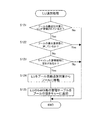
図4は、本発明の実施の形態の空き容量チェック処理のフローチャートであり、正LUへのデータの書き込み処理等によって、正LUから差分LUに差分データをコピーするときに、プールLU管理プログラム132によって実行される。
FIG. 4 is a flowchart of the free space check process according to the embodiment of this invention. When the differential data is copied from the primary LU to the differential LU by the data write process to the primary LU, the pool
まず、空きキューカウンタ205を参照して、プール(差分LU)の空き容量(既に使用されている容量でもよい)を確認する(S101)。
First, referring to the
次に、ステップS101で取得したプール領域の使用量と予め定めたLU追加閾値(70%)とを比較し、プール領域の使用量がLU追加閾値を超えているか否かを判定する(S102)。そして、プール領域の使用量がLU追加閾値(70%)を超えていれば、LU追加処理(図5)を実行する(S103)。 Next, the usage amount of the pool area acquired in step S101 is compared with a predetermined LU addition threshold (70%) to determine whether or not the usage amount of the pool area exceeds the LU addition threshold (S102). . If the pool area usage amount exceeds the LU addition threshold (70%), LU addition processing (FIG. 5) is executed (S103).
このLU追加閾値は、プール領域の使用量が100%に到達しないように余裕を持たせて70%程度とすることが望ましいが、ストレージ装置の稼働状態(例えば、データ入出力要求の量)によってLU追加閾値を変更することができる。 The LU addition threshold value is preferably about 70% with a margin so that the usage amount of the pool area does not reach 100%, but it depends on the operating state of the storage device (for example, the amount of data input / output requests). The LU addition threshold can be changed.
また、LUのプール領域への追加処理の実行中は通常時の値より高い閾値を設定することによって(例えば、通常時の70%に対して75%)、プール領域の使用量がLU追加閾値を超えたことによってLU追加処理が実行されているにもかかわらず、新たにLU追加処理の実行を防止することもできる。 In addition, by setting a threshold value higher than the normal value during execution of the LU addition process to the pool area (for example, 75% compared to 70% in the normal condition), the usage amount of the pool area becomes the LU addition threshold value. Even though the LU addition process is being executed due to exceeding this, it is possible to prevent the LU addition process from being newly executed.
次に、プール領域の使用量がI/O制限閾値(90%)を超えているか否かを判定する(S104)。その結果、プール領域の使用量がI/O制限閾値(90%)を超えていれば、ホスト3からのデータの書き込みを制限する(S105)。このI/O制限では、手動による仮想LUの削除処理を優先して、データ書き込み要求と差分データの削除処理とが1対1程度となるようにして、プール領域の使用量がこれ以上高くならないようにする。
Next, it is determined whether or not the usage amount of the pool area exceeds the I / O limit threshold (90%) (S104). As a result, if the use amount of the pool area exceeds the I / O limit threshold (90%), data writing from the
次に、プール領域の使用量が仮想LU解除閾値(95%)を超えているか否かを判定する(S106)。そして、プール領域の使用量が仮想LU解除閾値(95%)を超えていれば、仮想LU削除処理(図7)を実行する(S107)。この仮想LU削除処理によって運用の性能劣化を避けつつ、少量の空き容量を作ることができる。 Next, it is determined whether or not the usage amount of the pool area exceeds the virtual LU release threshold (95%) (S106). If the pool area usage exceeds the virtual LU release threshold (95%), a virtual LU deletion process (FIG. 7) is executed (S107). With this virtual LU deletion processing, a small amount of free space can be created while avoiding degradation of operational performance.
この仮想LU解除閾値は、プール領域の使用量が100%に到達する前に仮想LU削除処理を完了する必要があるので、若干の余裕を持たせて95%程度とすることが望ましいが、ストレージ装置の稼働状態(例えば、データ入出力要求の量)によって仮想LU解除閾値を変更することができる。 This virtual LU release threshold value should be about 95% with a slight margin because it is necessary to complete the virtual LU deletion process before the pool area usage reaches 100%. The virtual LU release threshold can be changed according to the operating state of the device (for example, the amount of data input / output requests).
また、1回目の判定では仮想LU解除閾値を95%とし、仮想LU削除処理中の2回目以後の判定では仮想LU解除閾値を高く設定する(例えば、96%とする)ことによって、プール領域の使用量が仮想LU解除閾値を超えたことによって仮想LU削除処理が実行されているにもかかわらず、新たに仮想LU削除処理が実行されないようにすることもできる。 In the first determination, the virtual LU release threshold is set to 95%, and in the second and subsequent determinations during the virtual LU deletion process, the virtual LU release threshold is set high (for example, set to 96%). Even if the virtual LU deletion process is executed because the usage amount exceeds the virtual LU release threshold, it is possible to prevent the virtual LU deletion process from being newly executed.
なお、プール領域の全容量が200GB以上の場合には、プール領域の使用量の割合ではなく、プール領域の残容量が10GB以下となったときに仮想LU削除処理を実行してもよい。 When the total capacity of the pool area is 200 GB or more, the virtual LU deletion process may be executed when the remaining capacity of the pool area becomes 10 GB or less, not the ratio of the usage amount of the pool area.
次に、プール領域の使用量が正LU解除閾値(99%)を超えているか否かを判定する(S108)。この正LU解除閾値によって、プール領域の使用量が100%に到達する可能性が極めて高く、緊急かつ確実に空き容量を確保する必要があることを判定する。そして、プール領域の使用量が正LU解除閾値(99%)を超えていれば、仮想LU削除処理(図11)を実行する(S107)。 Next, it is determined whether the usage amount of the pool area exceeds the primary LU release threshold (99%) (S108). Based on this primary LU release threshold, it is determined that there is a very high possibility that the usage amount of the pool area will reach 100%, and it is necessary to urgently and surely secure the free capacity. If the usage amount of the pool area exceeds the primary LU release threshold (99%), virtual LU deletion processing (FIG. 11) is executed (S107).
なお、プール領域の全容量が200GB以上の場合には、プール領域の使用量の割合ではなく、プール領域の残容量が2GB以下となったときに仮想LU削除処理を実行してもよい。 When the total capacity of the pool area is 200 GB or more, the virtual LU deletion process may be executed when the remaining capacity of the pool area becomes 2 GB or less, not the ratio of the usage amount of the pool area.
このように、複数段階で緊急度に応じた仮想LUの削除を実行するので、プール領域の使用量を確実に100%にさせないよういにすることができる。 As described above, since the virtual LU is deleted according to the degree of urgency in a plurality of stages, it is possible to ensure that the usage amount of the pool area is not 100%.
次に、プール領域の使用量が全仮想LU解除閾値(100%)に到達したか否かを判定する(S110)。そして、プール領域の使用量が100%に達していれば、ペア状態管理テーブルに記録されている当該プール領域を使用している仮想LUの状態を全てエラー状態(PSUE)にして、当該プール領域を使用している全ての仮想LUを削除する。 Next, it is determined whether the usage amount of the pool area has reached the all virtual LU release threshold (100%) (S110). If the usage amount of the pool area has reached 100%, the status of the virtual LU using the pool area recorded in the pair status management table is all set to the error state (PSUE), and the pool area Delete all virtual LUs that use.
このように、本発明の実施の形態の空き容量チェック処理では、管理者が介入することなく、指定条件に従って自動的に仮想LUを削除することができ、プール領域の使用量が100%となることを防止できる。また、プール領域の使用量に応じて段階的に仮想LUを削除するので、運用上の性能劣化を最小限に抑えることができる。 As described above, in the free space check processing according to the embodiment of this invention, the virtual LU can be automatically deleted according to the specified condition without intervention from the administrator, and the usage amount of the pool area becomes 100%. Can be prevented. In addition, since the virtual LU is deleted step by step according to the usage amount of the pool area, it is possible to minimize the performance degradation in operation.
図5は、本発明の実施の形態のLU追加処理のフローチャートであり、空き容量チェック処理(図4のステップS103)から呼び出されて(すなわち、プール領域の使用量がLU追加閾値(70%)を超えたときに)、プールLU管理プログラム132によって実行される。
FIG. 5 is a flowchart of the LU addition processing according to the embodiment of this invention, which is called from the free space check processing (step S103 in FIG. 4) (that is, the pool area usage is the LU addition threshold (70%)). Is executed by the pool
まず、プール自動追加対象管理テーブル143(図6)を参照して、プール自動追加対象にLUが登録されているか否かを判定する(S121)。そして、プール自動追加対象にLUが登録されていなければ、追加すべきLUが存在しないので、LUを追加することなくこの処理を終了する。一方、プール自動追加対象にLUが登録されていれば、ステップS122に進む。 First, referring to the pool automatic addition target management table 143 (FIG. 6), it is determined whether or not an LU is registered as a pool automatic addition target (S121). If no LU is registered as a pool automatic addition target, there is no LU to be added, and this process is terminated without adding an LU. On the other hand, if the LU is registered as a pool automatic addition target, the process proceeds to step S122.
ステップS122では、プール管理テーブル141(図6)を参照して、プール領域に登録されているLUが最大数に達しているか否かを判定する。このプール領域の登録数の最大値はプール管理テーブル141の容量によって定められる。そして、プール管理テーブル141に登録されているLUの数が既に最大数であれば、プール管理テーブル141に新たにLUを追加することができないので、LUを追加することなくこの処理を終了する。一方、プール管理テーブル141に登録されているLUの数が最大数に満たなければ、ステップS123に進む。 In step S122, with reference to the pool management table 141 (FIG. 6), it is determined whether or not the maximum number of LUs registered in the pool area has been reached. The maximum value of the number of registered pool areas is determined by the capacity of the pool management table 141. If the number of LUs registered in the pool management table 141 is already the maximum number, a new LU cannot be added to the pool management table 141, so this process is terminated without adding an LU. On the other hand, if the number of LUs registered in the pool management table 141 does not reach the maximum number, the process proceeds to step S123.
ステップS123では、キャッシュメモリ107の管理領域に空きがあるか否かを判定する。これは、プール領域にLUを追加することに伴い差分情報管理ブロック204の容量を増加することが必要なためである。そして、キャッシュメモリ107の管理領域に空きがなければ、差分情報管理ブロック204の領域を増やすことができないので、LUを追加することなくこの処理を終了する。一方、キャッシュメモリ107の管理領域に空きがあれば、ステップS124に進む。
In step S123, it is determined whether or not there is a free space in the management area of the
S121〜S123の処理によってLUを追加する条件が確認されたら、移動するLUをプール自動追加対象管理テーブル143から削除し、プール管理テーブル141に追加して、差分LUとして使用可能にする(S124)。 When the conditions for adding an LU are confirmed by the processing of S121 to S123, the LU to be moved is deleted from the pool automatic addition target management table 143, added to the pool management table 141, and made available as a differential LU (S124). .
この移動するLUとして、複数のLUをプール管理テーブル141に事前に指定しておくことができる。このようにすることで、必要な分だけLUを追加することが可能となる。例えば、100GBのLUを10個登録しておくと、プール領域の容量が300GB不足した場合に100GBのLUを3個だけプール領域に追加して、あとの7個のLUは、別の用途に使用可能となる。 As the LU to be moved, a plurality of LUs can be designated in advance in the pool management table 141. In this way, it is possible to add LUs as much as necessary. For example, if 10 100GB LUs are registered, if the capacity of the pool area is short of 300GB, only three 100GB LUs are added to the pool area, and the remaining 7 LUs can be used for other purposes. Can be used.
その後、従来から存在した差分情報管理ブロック204の最後の空きキューに、新たに増加した差分情報管理ブロック204の領域の空きキューのアドレスを設定し、新たに増加した空きキューを従来からの空きキューにつなげる(S125)。
Thereafter, the address of the empty queue in the area of the newly increased difference
図6は、本発明の実施の形態のLU追加処理の説明図である。 FIG. 6 is an explanatory diagram of LU addition processing according to the embodiment of this invention.
正LU(LU0)に対して、スナップショット生成時のデータのイメージを提供する仮想LU(LU2)が設けられている。このLU2は、正LUのデータと、プール領域にある差分データとによって構成される仮想的な論理ユニットである。すなわち、LU2に対するアクセスがあると、そのデータが正LUにあるのか、プール領域にある差分データなのかを判断して、差分LUに対するアクセスを実現している。 For the primary LU (LU0), a virtual LU (LU2) that provides an image of data at the time of snapshot generation is provided. This LU2 is a virtual logical unit composed of primary LU data and differential data in the pool area. That is, when there is an access to LU2, it is determined whether the data is in the primary LU or differential data in the pool area, and access to the differential LU is realized.
プール領域に追加されるLUは、プール自動追加対象管理テーブル143に登録されているもの(LU6、LU7)を、プール自動追加対象管理テーブル143から削除し、プール管理テーブル141に追加する。これによって、追加されたLUが差分LUとして使用可能となる。 As LUs added to the pool area, those registered in the pool automatic addition target management table 143 (LU6, LU7) are deleted from the pool automatic addition target management table 143 and added to the pool management table 141. As a result, the added LU can be used as a differential LU.
このように本発明の実施の形態のLU追加処理では、プール領域の容量を増加するためのLUを事前に複数用意しておき、プール領域の使用量がある閾値を越えた場合に、自動的にLUをプール領域に追加し、プール領域の容量を増加して、プール領域の使用量が100%になるのを防ぐ。また、プール領域の使用量が少なくて、LUを追加する必要がない場合は、LUを他の用途に使用することができる。よって、不要なディスクをプール領域に事前に登録することなく、ディスクの容量を有効に活用することができる。 As described above, in the LU addition processing according to the embodiment of the present invention, a plurality of LUs for increasing the capacity of the pool area are prepared in advance, and when the usage amount of the pool area exceeds a certain threshold value, it is automatically performed. The LU is added to the pool area to increase the capacity of the pool area and prevent the pool area usage from reaching 100%. Further, when the amount of use of the pool area is small and it is not necessary to add an LU, the LU can be used for other purposes. Therefore, it is possible to effectively use the capacity of the disk without registering unnecessary disks in the pool area in advance.
図7は、本発明の実施の形態の仮想LU削除処理(仮想LU単位)のフローチャートであり、空き容量チェック処理(図4のステップS107)から呼び出されて(すなわち、プール領域の使用量が仮想LU解除閾値(95%)を超えたときに)、プールLU管理プログラム132によって実行される。
FIG. 7 is a flowchart of virtual LU deletion processing (virtual LU unit) according to the embodiment of this invention, which is called from the free capacity check processing (step S107 in FIG. 4) (that is, the usage amount of the pool area is virtual). When the LU release threshold (95%) is exceeded), it is executed by the pool
まず、管理者が設定した情報に基づいて、削除する仮想LUを決定する(S131)。この削除するLUの設定には様々な方法がある。一つは、最も古い世代の仮想LUのデータを削除する方法である。また、管理者が指定した世代の仮想LUのデータを削除することもできる。なお、管理者が削除するLUを設定する画面は後述する(図9、図10)。 First, a virtual LU to be deleted is determined based on information set by the administrator (S131). There are various methods for setting the LU to be deleted. One is a method of deleting the data of the oldest generation virtual LU. It is also possible to delete generation LU data designated by the administrator. The screen for setting the LU to be deleted by the administrator will be described later (FIGS. 9 and 10).
また、最も古い仮想LUを選択するためには、全ての正LUのペア情報管理テーブル(図8)を参照して、仮想LUのペア状態とスナップショット作成日時を検索して、ペア状態がスプリット状態(PSUS)となっている仮想LUの中で、最も古い仮想LUを選択する。PAIR状態では仮想LUの実体がないため、実体があるスプリット状態の仮想LUを削除対象としている。 In order to select the oldest virtual LU, the pair status management table (FIG. 8) of all the primary LUs is referenced to search the virtual LU pair status and snapshot creation date and time, and the pair status is split. The oldest virtual LU is selected from the virtual LUs in the state (PSUS). Since there is no virtual LU entity in the PAIR state, the virtual LU in the split state with the entity is targeted for deletion.
そして、仮想LU単位の削除処理を登録し、この処理をバックグラウンドで実行する(S132)。この削除処理は、決定された仮想LUのデータを削除するものである。差分データは、複数世代に共通して用いられているものと、その削除対象の世代のみに用いられているものがあり、まず、差分データがこのいずれかであるかを判定する必要がある。差分情報管理ブロック204の世代管理微とマップを確認した結果、差分情報管理ブロック204が該当世代のみに使用されていれば、差分情報管理ブロック204のデータを更新して空きキューに変更する。一方、差分情報管理ブロック204を複数世代で共有されていれば、差分情報管理ブロック204の共有情報(世代管理ビットマップ)を更新する。
Then, a deletion process for each virtual LU is registered, and this process is executed in the background (S132). This deletion process is to delete the data of the determined virtual LU. There are two types of difference data that are commonly used for a plurality of generations and one that is used only for the generation to be deleted. First, it is necessary to determine whether the difference data is any of these. As a result of confirming the generation management fine and the map of the difference
そして、ペア情報管理テーブル(図8)に記録されている当該削除対象となる仮想LUのペア状態をエラー状態(PSUE)に変更してペアを解除し、この仮想LUを使用不可にする(S133)。 Then, the pair status of the virtual LU to be deleted recorded in the pair information management table (FIG. 8) is changed to the error status (PSUE), the pair is released, and this virtual LU is disabled (S133). ).
以上説明した仮想LU削除処理はプール領域の使用量が仮想LU解除閾値(95%)を超えたときに実行されるものであるが、削除対象の仮想LUを削除しても、プール領域の使用量がI/O制限閾値(90%)以下にならない場合には、当該仮想LUの削除を行わないようにしてもよい。 The virtual LU deletion process described above is executed when the pool area usage exceeds the virtual LU release threshold (95%). Even if the virtual LU to be deleted is deleted, the pool area usage If the amount does not fall below the I / O limit threshold (90%), the virtual LU may not be deleted.
このように仮想LU削除処理(仮想LU単位)は、削除対象の仮想LU(例えば、最も古い仮想LU等)のペア状態を解除し、スナップショットの維持に大きな影響を与えることなく、空き容量を作ることができる。また、管理者が設定した情報に基づいて削除する仮想LUを決定するので、古いデータであっても残すべき仮想LUを残して、LUの空き容量を増やすことができる。また、仮想LU削除処理をバックグランドで実行するので、運用の性能劣化を避けつつ、データの空き容量を作ることができる。 In this way, the virtual LU deletion process (virtual LU unit) cancels the pair status of the virtual LU to be deleted (for example, the oldest virtual LU), and frees up the free space without greatly affecting the maintenance of the snapshot. Can be made. Further, since the virtual LU to be deleted is determined based on the information set by the administrator, it is possible to increase the free capacity of the LU while leaving the virtual LU that should remain even if it is old data. In addition, since the virtual LU deletion process is executed in the background, it is possible to create a free data space while avoiding deterioration in operation performance.
図8は、本発明の実施の形態のペア情報管理テーブルの説明図である。 FIG. 8 is an explanatory diagram of a pair information management table according to the embodiment of this invention.
ペア情報管理テーブルは、正LU毎に設けられており、正LUと各世代の仮想LUのペア状態と、その仮想LUの作成日時を記録して、正LUと仮想LUとの関係を管理している。例えば、0番の正LUの13番の仮想LUは2003年11月24日22時30分30秒に作成され、現在もペア状態(PAIR)が維持されている。すなわち、13番の仮想LUは最新の仮想LUであり、現在の差分データの書き込みが行われている。 The pair information management table is provided for each primary LU, and records the pair status between the primary LU and each generation virtual LU and the creation date and time of the virtual LU, and manages the relationship between the primary LU and the virtual LU. ing. For example, the 0th primary LU, the 13th virtual LU, was created at 22:30:30 on November 24, 2003, and the pair status (PAIR) is still maintained. That is, the 13th virtual LU is the latest virtual LU, and the current differential data is being written.
また、0番の正LUの0番の仮想LUは2003年10月8日8時30分30秒にスナップショット作成要求が受け付けられることによって作成され、現在仮想LUが作成されたスプリット状態(PSUS)にある。このスプリット状態の仮想LUは削除対象となる。また、0番の正LUの9番の仮想LUは2003年9月20日10時10分10秒に作成されたが、既に削除された仮想LUであり、削除対象に登録されたエラー状態(PSUE)となっている。 Also, the 0th virtual LU of the 0th primary LU was created by accepting a snapshot creation request at 8:30:30 on October 8, 2003, and the split state (PSUS) where the current virtual LU was created )It is in. This split virtual LU is to be deleted. Also, the 9th virtual LU of the 0th primary LU was created at 10:10:10 on September 20, 2003, but was already deleted, and the error status ( PSUE).
ペア情報管理テーブルによって、削除対象のLUがチェック、削除登録がされ、削除する仮想LUが決定される。なお、削除対象LUの決定後、実際に差分データの削除はプール管理プログラム150が行う。
Based on the pair information management table, the LU to be deleted is checked and registered for deletion, and the virtual LU to be deleted is determined. Note that, after the deletion target LU is determined, the
図9は、本発明の実施の形態の仮想LU削除処理の設定画面の説明図である。 FIG. 9 is an explanatory diagram of a setting screen for virtual LU deletion processing according to the embodiment of this invention.
図9(a)は仮想LU削除情報設定のメイン画面であり、「削除可能」タブが選択された状態を示す。この画面では、削除優先順位について、仮想LUの作成日が「古い日付順から削除する。」のか、「指定した仮想LUを削除する。」のかを選択する。「指定した仮想LUを削除する。」が選択されると、「設定情報確認」ボタンがアクティブになる。そして「設定情報確認」ボタンを操作することによって、選択された正LUに関する削除優先順位設定サブ画面(図9(b))に移行する。削除優先順位設定サブ画面では、削除チェック欄をチェックすることによって、仮想LU毎に削除の許可を設定することができる。また、削除チェック欄にチェックを入れることによって優先順位を選択することができる。なお、優先順位は「高」「中」「低」のランクではなく、個別に順序を設定することもできる。 FIG. 9A is a main screen for setting virtual LU deletion information, and shows a state in which the “deletable” tab is selected. On this screen, for the deletion priority, select whether the creation date of the virtual LU is “Delete from the oldest date” or “Delete the specified virtual LU”. When “Delete specified virtual LU” is selected, the “Confirm setting information” button becomes active. Then, the “setting information confirmation” button is operated to shift to the deletion priority order setting sub screen (FIG. 9B) relating to the selected primary LU. On the deletion priority setting sub-screen, the deletion permission can be set for each virtual LU by checking the deletion check column. Also, the priority order can be selected by checking the deletion check column. Note that the priority order is not “high”, “medium”, and “low”, but the order may be set individually.
図10は、本発明の実施の形態の仮想LU削除処理の設定画面の説明図である。 FIG. 10 is an explanatory diagram of a setting screen for virtual LU deletion processing according to the embodiment of this invention.
図10(a)は仮想LU削除情報設定のメイン画面であり、「削除禁止」タブが選択された状態を示す。この画面では、正LUを選択し、「設定情報確認」ボタンを操作することによって、選択された正LUに関する削除禁止設定サブ画面(図10(b))に移行する。削除禁止設定サブ画面では、削除チェック欄をチェックすることによって、仮想LU毎に削除の禁止を設定することができる。 FIG. 10A is a main screen for setting virtual LU deletion information, and shows a state in which the “deletion prohibition” tab is selected. On this screen, the primary LU is selected and the “setting information confirmation” button is operated to move to the deletion prohibition setting subscreen (FIG. 10B) regarding the selected primary LU. In the deletion prohibition setting sub-screen, it is possible to set deletion prohibition for each virtual LU by checking the deletion check column.
図11は、本発明の実施の形態の仮想LU削除処理(正LU単位)のフローチャートであり、空き容量チェック処理(図4のステップS109)から呼び出されて(すなわち、プール領域の使用量が正LU解除閾値(99%)を超えたときに)、プールLU管理プログラム132によって実行される。
FIG. 11 is a flowchart of the virtual LU deletion process (primary LU unit) according to the embodiment of this invention, which is called from the free capacity check process (step S109 in FIG. 4) (that is, the pool area usage amount is normal). When the LU release threshold (99%) is exceeded), it is executed by the pool
まず、ペア情報管理テーブルを参照して仮想LUの削除中であるか否かを判定する。すなわち、ペア情報管理テーブルのペア状態欄が「PSUS」であれば仮想LUの削除中であると判定する(S141)。その結果、仮想LUの削除中であれば、仮想LUの削除を優先して速やかにプール領域の空き容量を確保するために、ステップS136に移行し、現在行われている削除処理を継続する。一方、仮想LUの削除中でなければ、新たに仮想LUの削除を実行する。 First, it is determined whether the virtual LU is being deleted with reference to the pair information management table. That is, if the pair status column of the pair information management table is “PSUS”, it is determined that the virtual LU is being deleted (S141). As a result, if the virtual LU is being deleted, the process proceeds to step S136 in order to quickly secure the free capacity of the pool area with priority given to the deletion of the virtual LU, and the current deletion process is continued. On the other hand, if the virtual LU is not being deleted, a new virtual LU is deleted.
そこで、まず、仮想LUの削除に対応する正LUを決定する(S142)。この正LUは、管理者が予め定めたものを選択する他に、ホスト3からデータ書き込み要求を受けている正LUを選択することができる。現在データ書き込み要求を送っているホストは、プール領域の空き容量が減少する原因となっている可能性が高いので、データ書き込み要求に係る正LUを選択することによって、当該ホストからのアクセスを止めることができる。
Therefore, first, a primary LU corresponding to the deletion of the virtual LU is determined (S142). As the primary LU, a primary LU that has received a data write request from the
そして、全てのホスト3からデータ書き込みを停止する(S143)。このデータ書き込みの停止によって、他の処理に優先して仮想LUの削除処理を行うことができ、速やかに空き容量を確保することができる。
Then, data writing from all the
そして、選択された正LUに関係する仮想LUの削除を実行する(S144)。この削除処理は、選択された正LUの正LUアドレステーブル203を参照して、差分情報管理ブロック204に登録された内容を削除し、当該アドレスの差分情報管理ブロック204のデータを空きキューにすることによって、仮想LUを削除し、プール領域の空き容量を確保する。この削除処理は、前述した仮想LU単位の削除処理(図7のS132)と比較して、差分情報管理ブロック204のデータ(世代管理ビットマップ)を参照して仮想LUの世代を特定する必要がないので、迅速に仮想LUを削除することができる。
Then, the virtual LU related to the selected primary LU is deleted (S144). This deletion processing refers to the primary LU address table 203 of the selected primary LU, deletes the contents registered in the differential
そして、プール領域の空き容量が確保されたなら、ホスト3からの書き込み処理を再開する(S145)。
When the free space in the pool area is secured, the writing process from the
このように仮想LU削除処理(正LU単位)は、閾値を超えたときに削除対象のせいLU(例えば、データ入出力要求があった正LU)に関係する全ての仮想LUのペア状態をPSUEにして、ペア状態を解除する。このペア解除処理は、バックグランドにて行うが、1回のJOBで大量(100MB程度)を削除できる。すなわち、選択された正LUに関係する全ての仮想LUを削除するために全ホストからのデータ書き込みを一時的に停止して、正LU単位で全体(又は、100MBなどの所定の容量ごと)にデータを削除して、一定のプール領域の空き容量を確保したうえで、ホストからのデータ書き込み要求を再開させる。よって、即座にかつ確実にプール領域の空き容量を増やすことができる。また、特定の正LUに関して仮想LUを削除するので、当該正LUに関係する特定のホストからのアクセスを止めることができる。 In this way, the virtual LU deletion process (primary LU unit) indicates the pair status of all virtual LUs related to the deletion-targeted LU (for example, the primary LU that requested the data input / output) when the threshold value is exceeded. To cancel the pair status. This pair cancellation processing is performed in the background, but a large amount (about 100 MB) can be deleted with one JOB. That is, in order to delete all virtual LUs related to the selected primary LU, data writing from all hosts is temporarily stopped, and the entire primary LU unit (or every predetermined capacity such as 100 MB). After deleting the data and securing a free space in a certain pool area, the data write request from the host is resumed. Therefore, the free capacity of the pool area can be increased immediately and reliably. Further, since the virtual LU is deleted for a specific primary LU, access from a specific host related to the primary LU can be stopped.
特許請求の範囲に記載した以外の本発明の観点の代表的なものとして、次のものがあげられる。 The following are typical examples of aspects of the present invention other than those described in the claims.
上位装置に接続され、前記上位装置からデータを受ける上位インタフェースと、
前記上位インタフェースに接続され、前記上位装置との間でやり取りされるデータ、及び前記上位装置との間でやり取りされるデータに関する制御情報を保存するメモリと、
前記メモリに接続され、前記上位装置との間でやり取りされるデータを、前記メモリに読み書きするように制御する複数のディスクインタフェースと、
前記複数のディスクインタフェースに接続され、前記複数のディスクインタフェースの制御のもとに、前記上位装置から送られたデータが格納される複数のディスクドライブと、
前記複数のディスクドライブの記憶領域を用いて生成される第1の論理ボリュームへのデータの読み書きを制御し、前記第1の論理ボリュームに格納された過去のデータを世代毎の差分データとして第2の論理ボリュームに書き込むように制御し、前記第2の論理ボリュームに格納されている前記世代毎の差分データの関係を管理するスナップショット管理テーブルを前記メモリの領域に設けることによって前記差分データを管理する制御プロセッサと、を有するディスクアレイ装置における制御方法であって、
前記制御プロセッサは、
前記第2の論理ボリュームに格納されたデータ量を管理し、
前記第2の論理ボリュームに格納されたデータ量が前記第2の論理ボリュームの容量の第1の割合を超えた場合、前記第2の論理ボリュームの容量を増加し、
前記第2の論理ボリュームに格納されたデータ量が前記第2の論理ボリュームの容量の第2の割合を超えた場合、前記第1の論理ボリュームに対するデータの書き込みを制限し、
前記第2の論理ボリュームに格納されたデータ量が前記第2の論理ボリュームの容量の第3の割合を超えた場合、前記第2の論理ボリュームに書き込まれた差分データのうち、特定の世代の差分データを削除し、
前記第2の論理ボリュームに格納されたデータ量が前記第2の論理ボリュームの容量の第4の割合を超えた場合、前記第2の論理ボリュームに書き込まれた差分データのうち、前記第1の論理ボリュームに対応するものを削除し、
前記第2の論理ボリュームに格納されたデータ量が前記第2の論理ボリュームの容量の第5の割合を超えた場合、前記第2の論理ボリュームに書き込まれた全ての差分データを削除するディスクアレイ装置の制御方法。
A host interface connected to the host device and receiving data from the host device;
A memory connected to the host interface and storing control information regarding data exchanged with the host device and data exchanged with the host device;
A plurality of disk interfaces connected to the memory and controlling the data exchanged with the host device to read and write to the memory;
A plurality of disk drives connected to the plurality of disk interfaces and storing data sent from the host device under the control of the plurality of disk interfaces;
Controls reading and writing of data to the first logical volume generated using the storage areas of the plurality of disk drives, and sets the past data stored in the first logical volume as second difference data for each generation. The difference data is managed by providing in the memory area a snapshot management table that controls the writing of the difference data for each generation stored in the second logical volume. A control method in a disk array device comprising:
The control processor is
Managing the amount of data stored in the second logical volume;
If the amount of data stored in the second logical volume exceeds a first percentage of the capacity of the second logical volume, increase the capacity of the second logical volume;
If the amount of data stored in the second logical volume exceeds a second percentage of the capacity of the second logical volume, restricting data writing to the first logical volume;
When the amount of data stored in the second logical volume exceeds a third ratio of the capacity of the second logical volume, of the differential data written to the second logical volume, a specific generation Delete the difference data,
When the amount of data stored in the second logical volume exceeds a fourth ratio of the capacity of the second logical volume, out of the differential data written to the second logical volume, the first Delete the one corresponding to the logical volume,
A disk array that deletes all differential data written to the second logical volume when the amount of data stored in the second logical volume exceeds a fifth ratio of the capacity of the second logical volume Control method of the device.
さらに、前記制御プロセッサは、最も古い世代の差分データを削除対象として決定するディスクアレイ装置の制御方法。 Furthermore, the control processor is a control method for a disk array device that determines the difference data of the oldest generation as a deletion target.
さらに、前記制御プロセッサは、1回目の判定では前記第1の所定値を超えたか否かの判定をし、差分データ削除処理中の2回目以後の判定では前記第1の所定値より大きい第2の所定値を用いて、前記第2の論理ボリュームに格納されたデータ量が前記第2の所定値を超えたか否かの判定をするディスクアレイ装置の制御方法。 Further, the control processor determines whether or not the first predetermined value has been exceeded in the first determination, and a second larger than the first predetermined value in the second and subsequent determinations during the difference data deletion process. The disk array apparatus control method for determining whether or not the amount of data stored in the second logical volume exceeds the second predetermined value using the predetermined value.
さらに、前記制御プロセッサは、前記削除する差分データに対応する前記第1の論理ボリュームを決定する前に、前記差分データの削除処理中か否かを判定し、前記差分データの削除処理中であれば、現在実行中の削除処理を優先して実行するディスクアレイ装置の制御方法。 Further, the control processor determines whether or not the difference data is being deleted before determining the first logical volume corresponding to the difference data to be deleted. For example, a method of controlling a disk array device that prioritizes deletion processing that is currently being executed.
1 ディスクアレイ装置
2 SAN
3 ホスト
4 LAN
5 管理用端末装置
10 ディスクアレイコントローラ
20 ディスク
101 CPU
102 メモリ
103 制御プログラム
104 データ転送コントローラ
105 フロントエンドインターフェース
106 バックエンドインターフェース
107 データバッファ
108 LANインターフェース
1
3
5
102
Claims (6)
データが格納される複数のディスク装置と、
前記上位装置との間でやり取りされるデータの前記ディスク装置への読み書きを制御する複数のディスクインタフェースと、
前記複数のディスクドライブの記憶領域を用いて生成される第1の論理ボリュームへのデータの読み書きを制御し、前記第1の論理ボリュームに格納された過去のデータを世代毎の差分データとして第2の論理ボリュームに書き込むように制御し、前記第2の論理ボリュームに格納されている前記世代毎の差分データの関係を管理するスナップショット管理テーブルを前記メモリの領域に設けることによって前記差分データを管理する制御プロセッサと、を有するディスクアレイ装置であって、
前記制御プロセッサは、
前記第2の論理ボリュームに格納されたデータ量を管理し、
前記第2の論理ボリュームに格納されたデータ量が前記第2の論理ボリュームの容量の第1の割合を超えた場合、前記第2の論理ボリュームの容量を増加し、
前記第2の論理ボリュームに格納されたデータ量が、前記第1の割合より大きい第2の割合を超えた場合、前記第1の論理ボリュームに対するデータの書き込みを制限し、
前記第2の論理ボリュームに格納されたデータ量が、前記第2の割合より大きい第3の割合を超えた場合、前記第2の論理ボリュームに書き込まれた差分データのうち、特定の世代の差分データを削除し、
前記第2の論理ボリュームに格納されたデータ量が、前記第3の割合より大きい第4の割合を超えた場合、前記第2の論理ボリュームに書き込まれた差分データのうち、前記特定の第1の論理ボリュームに対応するものを削除すること特徴とするディスクアレイ装置。 A host interface connected to the host device and receiving data from the host device;
A plurality of disk units for storing data; and
A plurality of disk interfaces for controlling reading and writing of data exchanged with the host device to the disk device;
Controls reading and writing of data to the first logical volume generated using the storage areas of the plurality of disk drives, and sets the past data stored in the first logical volume as second difference data for each generation. The difference data is managed by providing in the memory area a snapshot management table that controls the writing of the difference data for each generation stored in the second logical volume. A disk array device having a control processor ,
The control processor is
Managing the amount of data stored in the second logical volume;
If the amount of data stored in the second logical volume exceeds a first percentage of the capacity of the second logical volume, increase the capacity of the second logical volume ;
If the amount of data stored in the second logical volume exceeds a second ratio that is greater than the first ratio, restricting data writing to the first logical volume;
When the amount of data stored in the second logical volume exceeds a third ratio that is greater than the second ratio, a difference of a specific generation among the differential data written to the second logical volume Delete the data,
When the amount of data stored in the second logical volume exceeds a fourth ratio that is greater than the third ratio, among the differential data written to the second logical volume, the specific first A disk array device that deletes the one corresponding to the logical volume .
前記制御プロセッサは、前記第2の論理ボリュームに格納されたデータ量が、前記第2の論理ボリュームの容量に達した場合、前記第2の論理ボリュームに書き込まれた全ての差分データを削除することを特徴とするディスクアレイ装置。 The control processor deletes all differential data written in the second logical volume when the amount of data stored in the second logical volume reaches the capacity of the second logical volume. A disk array device.
前記上位インタフェースに接続され、前記上位装置との間でやり取りされるデータ、及び前記上位装置との間でやり取りされるデータに関する制御情報を保存するメモリを有し、 A memory connected to the upper interface and storing control information related to data exchanged with the upper device and data exchanged with the upper device;
前記ディスクインタフェースは、前記上位装置との間でやり取りされ、前記メモリに格納されるデータを、前記ディスク装置に書き込むように制御することを特徴とするディスクアレイ装置。 The disk interface device controls the disk interface to exchange data with the host device and write data stored in the memory to the disk device.
前記ディスクアレイ装置は、 The disk array device
上位装置に接続され、前記上位装置からデータを受ける上位インタフェースと、 A host interface connected to the host device and receiving data from the host device;
データが格納される複数のディスク装置と、 A plurality of disk units for storing data; and
前記上位装置との間でやり取りされるデータの前記ディスク装置への読み書きを制御する複数のディスクインタフェースと、 A plurality of disk interfaces for controlling reading and writing of data exchanged with the host device to the disk device;
前記複数のディスクドライブの記憶領域を用いて生成される第1の論理ボリュームへのデータの読み書きを制御し、前記第1の論理ボリュームに格納された過去のデータを世代毎の差分データとして第2の論理ボリュームに書き込むように制御し、前記第2の論理ボリュームに格納されている前記世代毎の差分データの関係を管理するスナップショット管理テーブルを前記メモリの領域に設けることによって前記差分データを管理する制御プロセッサと、を有し、 Controls reading and writing of data to the first logical volume generated using the storage areas of the plurality of disk drives, and sets the past data stored in the first logical volume as second difference data for each generation. The difference data is managed by providing in the memory area a snapshot management table that controls the writing of the difference data for each generation stored in the second logical volume. A control processor,
前記方法は、 The method
前記第2の論理ボリュームに格納されたデータ量を管理し、 Managing the amount of data stored in the second logical volume;
前記第2の論理ボリュームに格納されたデータ量が前記第2の論理ボリュームの容量の第1の割合を超えた場合、前記第2の論理ボリュームの容量を増加し、 If the amount of data stored in the second logical volume exceeds a first percentage of the capacity of the second logical volume, increase the capacity of the second logical volume;
前記第2の論理ボリュームに格納されたデータ量が、前記第1の割合より大きい第2の割合を超えた場合、前記第1の論理ボリュームに対するデータの書き込みを制限し、 If the amount of data stored in the second logical volume exceeds a second ratio that is greater than the first ratio, restricting data writing to the first logical volume;
前記第2の論理ボリュームに格納されたデータ量が、前記第2の割合より大きい第3の割合を超えた場合、前記第2の論理ボリュームに書き込まれた差分データのうち、特定の世代の差分データを削除し、 When the amount of data stored in the second logical volume exceeds a third ratio that is greater than the second ratio, a difference of a specific generation among the differential data written to the second logical volume Delete the data,
前記第2の論理ボリュームに格納されたデータ量が、前記第3の割合より大きい第4の割合を超えた場合、前記第2の論理ボリュームに書き込まれた差分データのうち、前記特定の第1の論理ボリュームに対応するものを削除すること特徴とするボリューム管理方法。 When the amount of data stored in the second logical volume exceeds a fourth ratio that is greater than the third ratio, among the differential data written to the second logical volume, the specific first A volume management method characterized by deleting one corresponding to the logical volume.
前記第2の論理ボリュームに格納されたデータ量が、前記第2の論理ボリュームの容量 The amount of data stored in the second logical volume is the capacity of the second logical volume.
に達した場合、前記第2の論理ボリュームに書き込まれた全ての差分データを削除するこIf all the difference data written to the second logical volume is deleted,
とを特徴とするボリューム管理方法。A volume management method characterized by the above.
前記ディスクアレイ装置は、前記上位インタフェースに接続され、前記上位装置との間 The disk array device is connected to the host interface and is connected to the host device.
でやり取りされるデータ、及び前記上位装置との間でやり取りされるデータに関する制御Related to data exchanged in the network and data exchanged with the host device
情報を保存するメモリを有し、Has a memory to store information,
前記方法は、前記上位装置との間でやり取りされ、前記メモリに格納されるデータを、 The method includes exchanging data with the host device and storing data in the memory.
前記ディスク装置に書き込むように制御することを特徴とするボリューム管理方法。A volume management method comprising controlling to write to the disk device.
Priority Applications (5)
| Application Number | Priority Date | Filing Date | Title |
|---|---|---|---|
| JP2004116115A JP4681249B2 (en) | 2004-04-09 | 2004-04-09 | Disk array device |
| US10/853,289 US7174438B2 (en) | 2004-04-09 | 2004-05-26 | Disk array apparatus |
| EP04257251A EP1585021B1 (en) | 2004-04-09 | 2004-11-23 | Disk array apparatus |
| DE602004011181T DE602004011181T2 (en) | 2004-04-09 | 2004-11-23 | The disk array device |
| US11/642,927 US7698518B2 (en) | 2004-04-09 | 2006-12-21 | Disk array with capacity management |
Applications Claiming Priority (1)
| Application Number | Priority Date | Filing Date | Title |
|---|---|---|---|
| JP2004116115A JP4681249B2 (en) | 2004-04-09 | 2004-04-09 | Disk array device |
Publications (3)
| Publication Number | Publication Date |
|---|---|
| JP2005301628A JP2005301628A (en) | 2005-10-27 |
| JP2005301628A5 JP2005301628A5 (en) | 2007-04-19 |
| JP4681249B2 true JP4681249B2 (en) | 2011-05-11 |
Family
ID=34909557
Family Applications (1)
| Application Number | Title | Priority Date | Filing Date |
|---|---|---|---|
| JP2004116115A Expired - Fee Related JP4681249B2 (en) | 2004-04-09 | 2004-04-09 | Disk array device |
Country Status (4)
| Country | Link |
|---|---|
| US (2) | US7174438B2 (en) |
| EP (1) | EP1585021B1 (en) |
| JP (1) | JP4681249B2 (en) |
| DE (1) | DE602004011181T2 (en) |
Families Citing this family (44)
| Publication number | Priority date | Publication date | Assignee | Title |
|---|---|---|---|---|
| US7389503B2 (en) * | 2004-04-16 | 2008-06-17 | International Business Machines Corporation | Apparatus and method to update code in an information storage and retrieval system while that system remains in normal operation |
| US8601035B2 (en) * | 2007-06-22 | 2013-12-03 | Compellent Technologies | Data storage space recovery system and method |
| JP4550717B2 (en) | 2005-10-28 | 2010-09-22 | 富士通株式会社 | Virtual storage system control apparatus, virtual storage system control program, and virtual storage system control method |
| JP4920979B2 (en) | 2006-01-25 | 2012-04-18 | 株式会社日立製作所 | Storage apparatus and control method thereof |
| JP5037881B2 (en) * | 2006-04-18 | 2012-10-03 | 株式会社日立製作所 | Storage system and control method thereof |
| JP5134915B2 (en) * | 2007-11-02 | 2013-01-30 | 株式会社日立製作所 | Storage area configuration optimization method, computer system, and management computer |
| US8959307B1 (en) | 2007-11-16 | 2015-02-17 | Bitmicro Networks, Inc. | Reduced latency memory read transactions in storage devices |
| JP4607981B2 (en) | 2008-03-27 | 2011-01-05 | 富士通株式会社 | Copy control apparatus, copy control method, and copy control program |
| JP2010092177A (en) * | 2008-10-06 | 2010-04-22 | Hitachi Ltd | Information processor and operation method of storage system |
| US8291261B2 (en) * | 2008-11-05 | 2012-10-16 | Vulcan Technologies Llc | Lightweight application-level runtime state save-and-restore utility |
| JP5317807B2 (en) * | 2009-04-13 | 2013-10-16 | 株式会社日立製作所 | File control system and file control computer used therefor |
| US8665601B1 (en) | 2009-09-04 | 2014-03-04 | Bitmicro Networks, Inc. | Solid state drive with improved enclosure assembly |
| US9135190B1 (en) | 2009-09-04 | 2015-09-15 | Bitmicro Networks, Inc. | Multi-profile memory controller for computing devices |
| US8447908B2 (en) | 2009-09-07 | 2013-05-21 | Bitmicro Networks, Inc. | Multilevel memory bus system for solid-state mass storage |
| US8560804B2 (en) * | 2009-09-14 | 2013-10-15 | Bitmicro Networks, Inc. | Reducing erase cycles in an electronic storage device that uses at least one erase-limited memory device |
| US8566541B2 (en) * | 2010-09-14 | 2013-10-22 | Hitachi, Ltd. | Storage system storing electronic modules applied to electronic objects common to several computers, and storage control method for the same |
| US9372755B1 (en) | 2011-10-05 | 2016-06-21 | Bitmicro Networks, Inc. | Adaptive power cycle sequences for data recovery |
| US9043669B1 (en) | 2012-05-18 | 2015-05-26 | Bitmicro Networks, Inc. | Distributed ECC engine for storage media |
| US20140281306A1 (en) * | 2013-03-14 | 2014-09-18 | Hitachi, Ltd. | Method and apparatus of non-disruptive storage migration |
| US9423457B2 (en) | 2013-03-14 | 2016-08-23 | Bitmicro Networks, Inc. | Self-test solution for delay locked loops |
| US9934045B1 (en) | 2013-03-15 | 2018-04-03 | Bitmicro Networks, Inc. | Embedded system boot from a storage device |
| US9672178B1 (en) | 2013-03-15 | 2017-06-06 | Bitmicro Networks, Inc. | Bit-mapped DMA transfer with dependency table configured to monitor status so that a processor is not rendered as a bottleneck in a system |
| US9875205B1 (en) | 2013-03-15 | 2018-01-23 | Bitmicro Networks, Inc. | Network of memory systems |
| US9916213B1 (en) | 2013-03-15 | 2018-03-13 | Bitmicro Networks, Inc. | Bus arbitration with routing and failover mechanism |
| US9400617B2 (en) | 2013-03-15 | 2016-07-26 | Bitmicro Networks, Inc. | Hardware-assisted DMA transfer with dependency table configured to permit-in parallel-data drain from cache without processor intervention when filled or drained |
| US9720603B1 (en) | 2013-03-15 | 2017-08-01 | Bitmicro Networks, Inc. | IOC to IOC distributed caching architecture |
| US9430386B2 (en) | 2013-03-15 | 2016-08-30 | Bitmicro Networks, Inc. | Multi-leveled cache management in a hybrid storage system |
| US10489318B1 (en) | 2013-03-15 | 2019-11-26 | Bitmicro Networks, Inc. | Scatter-gather approach for parallel data transfer in a mass storage system |
| US9842024B1 (en) | 2013-03-15 | 2017-12-12 | Bitmicro Networks, Inc. | Flash electronic disk with RAID controller |
| US9798688B1 (en) | 2013-03-15 | 2017-10-24 | Bitmicro Networks, Inc. | Bus arbitration with routing and failover mechanism |
| US9501436B1 (en) | 2013-03-15 | 2016-11-22 | Bitmicro Networks, Inc. | Multi-level message passing descriptor |
| US9734067B1 (en) | 2013-03-15 | 2017-08-15 | Bitmicro Networks, Inc. | Write buffering |
| US9858084B2 (en) | 2013-03-15 | 2018-01-02 | Bitmicro Networks, Inc. | Copying of power-on reset sequencer descriptor from nonvolatile memory to random access memory |
| US9971524B1 (en) | 2013-03-15 | 2018-05-15 | Bitmicro Networks, Inc. | Scatter-gather approach for parallel data transfer in a mass storage system |
| US9952991B1 (en) | 2014-04-17 | 2018-04-24 | Bitmicro Networks, Inc. | Systematic method on queuing of descriptors for multiple flash intelligent DMA engine operation |
| US9811461B1 (en) | 2014-04-17 | 2017-11-07 | Bitmicro Networks, Inc. | Data storage system |
| US10055150B1 (en) | 2014-04-17 | 2018-08-21 | Bitmicro Networks, Inc. | Writing volatile scattered memory metadata to flash device |
| US10078604B1 (en) | 2014-04-17 | 2018-09-18 | Bitmicro Networks, Inc. | Interrupt coalescing |
| US10042792B1 (en) | 2014-04-17 | 2018-08-07 | Bitmicro Networks, Inc. | Method for transferring and receiving frames across PCI express bus for SSD device |
| US10025736B1 (en) | 2014-04-17 | 2018-07-17 | Bitmicro Networks, Inc. | Exchange message protocol message transmission between two devices |
| US9916110B2 (en) * | 2016-02-23 | 2018-03-13 | Red Hat, Inc. | Size adjustable volumes for containers |
| US10552050B1 (en) | 2017-04-07 | 2020-02-04 | Bitmicro Llc | Multi-dimensional computer storage system |
| CN110673797A (en) * | 2019-09-20 | 2020-01-10 | 浪潮电子信息产业股份有限公司 | Logical volume copying method in distributed block storage service |
| CN115220647A (en) * | 2021-04-21 | 2022-10-21 | 伊姆西Ip控股有限责任公司 | Method, electronic device and computer program product for storage management |
Citations (4)
| Publication number | Priority date | Publication date | Assignee | Title |
|---|---|---|---|---|
| JP2002278819A (en) * | 2001-03-21 | 2002-09-27 | Toshiba Corp | Generation management method for snap shot image, storage medium and generation management system |
| US20040030951A1 (en) * | 2002-08-06 | 2004-02-12 | Philippe Armangau | Instantaneous restoration of a production copy from a snapshot copy in a data storage system |
| US20040068636A1 (en) * | 2002-10-03 | 2004-04-08 | Michael Jacobson | Virtual storage systems, virtual storage methods and methods of over committing a virtual raid storage system |
| JP2005050024A (en) * | 2003-07-31 | 2005-02-24 | Toshiba Corp | Computer system and program |
Family Cites Families (10)
| Publication number | Priority date | Publication date | Assignee | Title |
|---|---|---|---|---|
| US5403639A (en) | 1992-09-02 | 1995-04-04 | Storage Technology Corporation | File server having snapshot application data groups |
| US6324654B1 (en) * | 1998-03-30 | 2001-11-27 | Legato Systems, Inc. | Computer network remote data mirroring system |
| US6374266B1 (en) | 1998-07-28 | 2002-04-16 | Ralph Shnelvar | Method and apparatus for storing information in a data processing system |
| US6260125B1 (en) | 1998-12-09 | 2001-07-10 | Ncr Corporation | Asynchronous write queues, reconstruction and check-pointing in disk-mirroring applications |
| US6473775B1 (en) | 2000-02-16 | 2002-10-29 | Microsoft Corporation | System and method for growing differential file on a base volume of a snapshot |
| JP3868708B2 (en) | 2000-04-19 | 2007-01-17 | 株式会社日立製作所 | Snapshot management method and computer system |
| US6584551B1 (en) | 2000-11-27 | 2003-06-24 | Lsi Logic Corporation | System and method for automatic dynamic expansion of a snapshot repository |
| US7475098B2 (en) | 2002-03-19 | 2009-01-06 | Network Appliance, Inc. | System and method for managing a plurality of snapshots |
| US7266654B2 (en) | 2003-03-18 | 2007-09-04 | Hitachi, Ltd. | Storage system, server apparatus, and method for creating a plurality of snapshots |
| US7111136B2 (en) | 2003-06-26 | 2006-09-19 | Hitachi, Ltd. | Method and apparatus for backup and recovery system using storage based journaling |
-
2004
- 2004-04-09 JP JP2004116115A patent/JP4681249B2/en not_active Expired - Fee Related
- 2004-05-26 US US10/853,289 patent/US7174438B2/en not_active Expired - Fee Related
- 2004-11-23 EP EP04257251A patent/EP1585021B1/en not_active Expired - Fee Related
- 2004-11-23 DE DE602004011181T patent/DE602004011181T2/en active Active
-
2006
- 2006-12-21 US US11/642,927 patent/US7698518B2/en not_active Expired - Fee Related
Patent Citations (5)
| Publication number | Priority date | Publication date | Assignee | Title |
|---|---|---|---|---|
| JP2002278819A (en) * | 2001-03-21 | 2002-09-27 | Toshiba Corp | Generation management method for snap shot image, storage medium and generation management system |
| US20040030951A1 (en) * | 2002-08-06 | 2004-02-12 | Philippe Armangau | Instantaneous restoration of a production copy from a snapshot copy in a data storage system |
| US20040068636A1 (en) * | 2002-10-03 | 2004-04-08 | Michael Jacobson | Virtual storage systems, virtual storage methods and methods of over committing a virtual raid storage system |
| JP2004127301A (en) * | 2002-10-03 | 2004-04-22 | Hewlett-Packard Development Co Lp | Virtual storage system, virtual storage method, and method of over assigning virtual raid storage system |
| JP2005050024A (en) * | 2003-07-31 | 2005-02-24 | Toshiba Corp | Computer system and program |
Also Published As
| Publication number | Publication date |
|---|---|
| US7174438B2 (en) | 2007-02-06 |
| DE602004011181D1 (en) | 2008-02-21 |
| DE602004011181T2 (en) | 2009-01-08 |
| US20050228944A1 (en) | 2005-10-13 |
| JP2005301628A (en) | 2005-10-27 |
| EP1585021A1 (en) | 2005-10-12 |
| US20070118703A1 (en) | 2007-05-24 |
| US7698518B2 (en) | 2010-04-13 |
| EP1585021B1 (en) | 2008-01-09 |
Similar Documents
| Publication | Publication Date | Title |
|---|---|---|
| JP4681249B2 (en) | Disk array device | |
| JP4681247B2 (en) | Disk array device and disk array device control method | |
| US6694413B1 (en) | Computer system and snapshot data management method thereof | |
| US7783850B2 (en) | Method and apparatus for master volume access during volume copy | |
| US7028216B2 (en) | Disk array system and a method of avoiding failure of the disk array system | |
| JP4439960B2 (en) | Storage device | |
| US7680984B2 (en) | Storage system and control method for managing use of physical storage areas | |
| US8661215B2 (en) | System and method of acquiring and copying snapshots | |
| US7593973B2 (en) | Method and apparatus for transferring snapshot data | |
| US8170996B2 (en) | Storage subsystem | |
| JP4452533B2 (en) | System and storage system | |
| JP4398463B2 (en) | Method, system, and program for incremental virtual copy | |
| US20070294495A1 (en) | Storage control apparatus, storage control program, and storage control method | |
| US20060224639A1 (en) | Backup system, program and backup method | |
| JP2004264973A (en) | Method for controlling storage system, storage system, information processing apparatus, management computer, and program | |
| JP2010079526A (en) | Computer system and method for managing hierarchy of journal | |
| JP2005322237A (en) | Point in time copy between data storage | |
| JP2008269374A (en) | Storage system and control method | |
| JP2006011811A (en) | Storage control system and storage control method | |
| JP4394467B2 (en) | Storage system, server apparatus, and preceding copy data generation method | |
| JP2015501959A (en) | Storage system and storage control method |
Legal Events
| Date | Code | Title | Description |
|---|---|---|---|
| A521 | Written amendment |
Free format text: JAPANESE INTERMEDIATE CODE: A523 Effective date: 20070302 |
|
| A621 | Written request for application examination |
Free format text: JAPANESE INTERMEDIATE CODE: A621 Effective date: 20070302 |
|
| A131 | Notification of reasons for refusal |
Free format text: JAPANESE INTERMEDIATE CODE: A131 Effective date: 20100202 |
|
| A521 | Written amendment |
Free format text: JAPANESE INTERMEDIATE CODE: A523 Effective date: 20100325 |
|
| TRDD | Decision of grant or rejection written | ||
| A01 | Written decision to grant a patent or to grant a registration (utility model) |
Free format text: JAPANESE INTERMEDIATE CODE: A01 Effective date: 20110111 |
|
| A01 | Written decision to grant a patent or to grant a registration (utility model) |
Free format text: JAPANESE INTERMEDIATE CODE: A01 |
|
| A61 | First payment of annual fees (during grant procedure) |
Free format text: JAPANESE INTERMEDIATE CODE: A61 Effective date: 20110204 |
|
| R150 | Certificate of patent or registration of utility model |
Free format text: JAPANESE INTERMEDIATE CODE: R150 |
|
| FPAY | Renewal fee payment (event date is renewal date of database) |
Free format text: PAYMENT UNTIL: 20140210 Year of fee payment: 3 |
|
| LAPS | Cancellation because of no payment of annual fees |