JP4681247B2 - Disk array device and disk array device control method - Google Patents
Disk array device and disk array device control method Download PDFInfo
- Publication number
- JP4681247B2 JP4681247B2 JP2004114189A JP2004114189A JP4681247B2 JP 4681247 B2 JP4681247 B2 JP 4681247B2 JP 2004114189 A JP2004114189 A JP 2004114189A JP 2004114189 A JP2004114189 A JP 2004114189A JP 4681247 B2 JP4681247 B2 JP 4681247B2
- Authority
- JP
- Japan
- Prior art keywords
- logical volume
- capacity
- pool
- data
- management table
- Prior art date
- Legal status (The legal status is an assumption and is not a legal conclusion. Google has not performed a legal analysis and makes no representation as to the accuracy of the status listed.)
- Expired - Fee Related
Links
Images


Classifications
-
- G—PHYSICS
- G06—COMPUTING; CALCULATING OR COUNTING
- G06F—ELECTRIC DIGITAL DATA PROCESSING
- G06F3/00—Input arrangements for transferring data to be processed into a form capable of being handled by the computer; Output arrangements for transferring data from processing unit to output unit, e.g. interface arrangements
- G06F3/06—Digital input from, or digital output to, record carriers, e.g. RAID, emulated record carriers or networked record carriers
- G06F3/0601—Interfaces specially adapted for storage systems
- G06F3/0628—Interfaces specially adapted for storage systems making use of a particular technique
- G06F3/0662—Virtualisation aspects
- G06F3/0665—Virtualisation aspects at area level, e.g. provisioning of virtual or logical volumes
-
- G—PHYSICS
- G06—COMPUTING; CALCULATING OR COUNTING
- G06F—ELECTRIC DIGITAL DATA PROCESSING
- G06F3/00—Input arrangements for transferring data to be processed into a form capable of being handled by the computer; Output arrangements for transferring data from processing unit to output unit, e.g. interface arrangements
- G06F3/06—Digital input from, or digital output to, record carriers, e.g. RAID, emulated record carriers or networked record carriers
- G06F3/0601—Interfaces specially adapted for storage systems
- G06F3/0602—Interfaces specially adapted for storage systems specifically adapted to achieve a particular effect
- G06F3/0608—Saving storage space on storage systems
-
- G—PHYSICS
- G06—COMPUTING; CALCULATING OR COUNTING
- G06F—ELECTRIC DIGITAL DATA PROCESSING
- G06F3/00—Input arrangements for transferring data to be processed into a form capable of being handled by the computer; Output arrangements for transferring data from processing unit to output unit, e.g. interface arrangements
- G06F3/06—Digital input from, or digital output to, record carriers, e.g. RAID, emulated record carriers or networked record carriers
- G06F3/0601—Interfaces specially adapted for storage systems
- G06F3/0628—Interfaces specially adapted for storage systems making use of a particular technique
- G06F3/0638—Organizing or formatting or addressing of data
- G06F3/0644—Management of space entities, e.g. partitions, extents, pools
-
- G—PHYSICS
- G06—COMPUTING; CALCULATING OR COUNTING
- G06F—ELECTRIC DIGITAL DATA PROCESSING
- G06F3/00—Input arrangements for transferring data to be processed into a form capable of being handled by the computer; Output arrangements for transferring data from processing unit to output unit, e.g. interface arrangements
- G06F3/06—Digital input from, or digital output to, record carriers, e.g. RAID, emulated record carriers or networked record carriers
- G06F3/0601—Interfaces specially adapted for storage systems
- G06F3/0668—Interfaces specially adapted for storage systems adopting a particular infrastructure
- G06F3/067—Distributed or networked storage systems, e.g. storage area networks [SAN], network attached storage [NAS]
Description
本発明は、ディスクアレイ装置に関し、特にスナップショットにおける差分LUの管理技術に関する。 The present invention relates to a disk array device, and more particularly to a management technique for differential LU in a snapshot.
コンピュータシステムにおいては、ストレージ装置に記憶されるデータをバックアップする場合など、元のデータを記憶した記憶ボリュームの複製を生成する場合がある、この場合、元のデータを記憶した記憶ボリュームと複製データを記憶した記憶ボリュームとは内容が一致し整合性が保たれる必要がある。そのためには複製の生成が完了するまでの間、元のデータを記憶した記憶ボリュームの更新を停止させる必要がある。しかし高可用性が求められるコンピュータシステムなどでは、元のデータを記憶した記憶ボリュームに対するアクセスを停止することができない場合がある。 In a computer system, there may be a case where a copy of a storage volume that stores the original data is generated, such as when data stored in the storage device is backed up. In this case, the storage volume that stores the original data and the copy data are generated. The stored storage volume must have the same content and be consistent. For this purpose, it is necessary to stop updating the storage volume storing the original data until the generation of the replica is completed. However, in a computer system or the like that requires high availability, access to the storage volume that stores the original data may not be stopped.
そこで、元のデータを記憶した記憶ボリュームと複製データを記憶した記憶ボリュームとの間である時点での整合性を保ち、ある時点の後に元のデータが更新されたとしてもある時点の元のデータを参照できるようにするスナップショットと呼ばれる技術が開発されている。 Therefore, the consistency between the storage volume storing the original data and the storage volume storing the replicated data is maintained at a certain point in time, and even if the original data is updated after a certain point, the original data at a certain point A technique called “snapshot” has been developed so that it can be referred to.
スナップショットの技術によれば、整合性を保つべき時点の後に元のデータが更新される場合には、整合性を保つべき時点のデータを別の記憶ボリュームに記憶するようにする。つまり元のデータは、更新されなければそのままであり、更新される場合には整合性を保つべき時点のデータが別の記憶ボリュームに記憶される。
しかし、スナップショット機能は、正LUの容量よりも差分LUの容量を減らせることが利点であるが、ホストからのデータの書き込みが多くなると差分データが多くなる。そして、差分LUの使用量が100%になるとスナップショットを維持できなくなる。このため、事前に差分LUとして多くのLUを設定すると、データの書き込みが多く発生しなかった場合に他の用途に使用することができない。 However, the snapshot function is advantageous in that the capacity of the differential LU can be reduced compared to the capacity of the primary LU, but the amount of differential data increases as the number of data writes from the host increases. When the usage amount of the differential LU reaches 100%, the snapshot cannot be maintained. For this reason, if a large number of LUs are set in advance as differential LUs, they cannot be used for other purposes when a large amount of data writing does not occur.
本発明は、スナップショットにおいて使用される差分LUの容量を増減することによって、ストレージ装置のリソースを有効に活用することを目的とする。 An object of the present invention is to effectively utilize the resources of a storage apparatus by increasing or decreasing the capacity of a differential LU used in a snapshot.
上位装置に接続され、前記上位装置からデータを受ける上位インタフェースと、前記上位インタフェースに接続され、前記上位装置との間でやり取りされるデータ、及び前記上位装置との間でやり取りされるデータに関する制御情報を保存するメモリと、前記メモリに接続され、前記上位装置との間でやり取りされるデータを、前記メモリに読み書きするように制御する複数のディスクインタフェースと、前記複数のディスクインタフェースに接続され、前記複数のディスクインタフェースの制御のもとに、前記上位装置から送られたデータが格納される複数のディスクドライブと、前記複数のディスクドライブの記憶領域を用いて生成される第1の論理ボリュームへのデータの読み書きを制御し、前記第1の論理ボリュームに格納された過去のデータを世代毎の差分データとして第2の論理ボリュームに書き込むように制御し、前記第2の論理ボリュームに格納されている前記世代毎の差分データの関係を管理するスナップショット管理テーブルを前記メモリの管理領域に設けることによって前記差分データを管理する制御プロセッサと、を有し、前記制御プロセッサは、前記第2の論理ボリュームに格納されたデータ量を管理し、前記第2の論理ボリュームに格納されたデータ量が前記第2の論理ボリュームの容量の第1の割合を超えた場合、前記管理領域に空きがあるか否かを判定し、前記管理領域に空きがある場合、前記第2の論理ボリュームの容量を増加するための条件が満たされると判定し、前記第2の論理ボリュームの容量を増加し、前記管理領域にてスナップショット管理テーブルの容量を増加し、前記第2の論理ボリュームに格納されたデータ量が前記第2の論理ボリュームの容量の第2の割合より少なくなった場合、前記第2の論理ボリュームの容量を減少させ、該減少させた前記第2の論理ボリュームの容量を他用途に使用可能とするディスクアレイ装置。 Control related to a host interface connected to a host device and receiving data from the host device, data connected to the host interface and exchanged with the host device, and data exchanged with the host device A memory for storing information, a plurality of disk interfaces connected to the memory and controlled to read / write data to / from the host device, and connected to the plurality of disk interfaces; Under control of the plurality of disk interfaces, a plurality of disk drives storing data sent from the host device and a first logical volume created using storage areas of the plurality of disk drives Control the reading and writing of the data stored in the first logical volume. A snapshot management table that controls to write the difference data for each generation into the second logical volume and manages the relationship of the difference data for each generation stored in the second logical volume. And a control processor that manages the difference data by providing the management data in the management area, and the control processor manages the amount of data stored in the second logical volume and stores it in the second logical volume. When the amount of data that has been exceeded exceeds the first ratio of the capacity of the second logical volume, it is determined whether or not there is a free space in the management area. It is determined that the condition for increasing the capacity of the logical volume is satisfied, the capacity of the second logical volume is increased, and a snapshot is created in the management area. If the amount of data stored in the second logical volume is smaller than a second ratio of the capacity of the second logical volume, the capacity of the second logical volume is increased. A disk array device that reduces the capacity of the second logical volume that can be used for other purposes.
本発明によると、プール領域に登録されているLUの容量を増減することによって、ストレージ装置のリソースを有効に活用することができる。 According to the present invention, it is possible to effectively use the resources of the storage apparatus by increasing or decreasing the capacity of the LU registered in the pool area.
以下、本発明の実施の形態を図面を参照して説明する。 Hereinafter, embodiments of the present invention will be described with reference to the drawings.
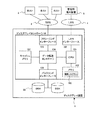
図1は、本発明の実施の形態のディスクアレイ装置の構成を示すブロック図である。 FIG. 1 is a block diagram showing a configuration of a disk array device according to an embodiment of the present invention.
本発明の実施の形態のディスクアレイ装置1は、ディスクアレイコントローラ10及びディスク20を含んで構成されている。また、ディスクアレイ装置1は、SAN2を介して複数のホスト3に接続されており、LAN4を介して管理用端末装置5に接続されている。
The disk array device 1 according to the embodiment of the present invention includes a disk array controller 10 and a
ディスクアレイコントローラ10は制御プログラム103の動作によって、ディスク20に対するデータの入出力を制御する。また、ディスク20によってRAID(Redundant Array of Independent Disks)が構成されており、記憶されるデータに冗長性を持たせている。このため、ディスクの一部に障害が生じても、記憶されたデータが消失しないようになっている。
The disk array controller 10 controls data input / output with respect to the
ディスクアレイコントローラ10には、CPU101、メモリ102、データ転送コントローラ104、フロントエンドインターフェース105、バックエンドインターフェース106、キャッシュメモリ107、及びLANインターフェース108が設けられている。
The disk array controller 10 includes a
メモリ102には制御プログラム103(図2参照)が記憶されており、CPU101が制御プログラム103を呼び出して実行することによって各種処理が行われる。
A control program 103 (see FIG. 2) is stored in the
データ転送コントローラ104は、CPU101、フロントエンドインターフェース105、バックエンドインターフェース106、及びキャッシュメモリ107の間でデータを転送する。
The
フロントエンドインターフェース105は、SAN2に対するインターフェースであって、例えば、ファイバチャネルプロトコルによって、ホスト3との間でデータや制御信号を送受信する。
The front-
バックエンドインターフェース106は、ディスク20に対するインターフェースであって、例えば、ファイバチャネルプロトコルによって、ディスク20との間でデータや制御信号を送受信する。
The back-
キャッシュメモリ107には、フロントエンドインターフェース105とバックエンドインターフェース106との間で送受信されるデータが一時的に記憶されるキャッシュが設けられている。
The
すなわち、データ転送コントローラ104は、SAN4を介してディスクに読み書きされるデータをインターフェース105、106間で転送する。さらに、これらのディスクに読み書きされるデータをキャッシュメモリ107に転送する。
That is, the
LANインターフェース108は、LAN4に対するインターフェースであって、例えば、TCP/IPプロトコルによって、管理用端末装置5との間でデータや制御信号を送受信することができる。
The
SAN2は、例えばファイバチャネルプロトコルのような、データの転送に適するプロトコルで通信可能なネットワークである。 The SAN 2 is a network that can communicate with a protocol suitable for data transfer, such as a fiber channel protocol.
ホスト3は、CPU、メモリ、記憶装置、インターフェース、入力装置及び表示装置が備わるコンピュータ装置であり、ディスクアレイ装置1から提供されるデータを利用して、データベースサービスやウェブサービス等を利用可能にする。
The
LAN4は、ディスクアレイ装置1の管理用に用いられるもので、例えば、TCP/IPプロトコルによって、コンピュータ間でデータや制御情報を通信可能であり、例えばイーサネット(登録商標、以下同じ)が用いられる。 The LAN 4 is used for managing the disk array device 1, and can communicate data and control information between computers by, for example, the TCP / IP protocol. For example, Ethernet (registered trademark, the same applies hereinafter) is used.
管理用端末装置5は、CPU、メモリ、記憶装置、インターフェース、入力装置及び表示装置が備わるコンピュータ装置である。管理用端末装置5では管理プログラムが動作しており、該管理プログラムによってディスクアレイ装置1の動作状態を把握し、ディスクアレイ装置1の動作を制御する。なお、管理用端末装置5ではwebブラウザ等のクライアントプログラムが動作しており、ディスクアレイ装置1からCGI(Common Gateway Interface)等によって供給される管理プログラムによってディスクアレイ装置1の動作を制御するようにしてもよい。
The
図2は、本発明の実施の形態の制御プログラム103の説明図である。
FIG. 2 is an explanatory diagram of the
ホスト3の通常I/O処理プログラム301から送られたデータ入出力要求は、ディスクアレイ装置1の制御プログラム103のR/Wコマンド解析プログラム111によって解析され、スナップジョブプログラム121に送られる。
The data input / output request sent from the normal I /
スナップジョブプログラム121は、正LUに対するデータ書き込み要求を受信すると、正LU内の更新前のデータを差分LUに複写し、この複写後に正LUの内容を更新する。更に、スナップジョブプログラム121は、データが更新された正LU内のブロックに対応する仮想LU内のブロックを、スナップショット生成要求の受信時点で正LUのデータ(すなわち更新前のデータ)が格納されている差分LU上のブロックと対応付けるようスナップショット管理テーブル(差分情報管理ブロック204)を更新する。
When the
また、スナップリストアジョブプログラム122は、仮想LUに対するアクセス要求を受信すると、スナップショット管理テーブルを参照して、仮想LUのブロックと対応付けられている正LUのブロック又は差分LUのブロックにアクセスする。このようにして、ディスクアレイ装置1はスナップショットイメージを提供することが可能になる。そして、ホスト3が、通常I/O処理プログラム301によって、仮想LUにアクセスすることによって、スナップショット生成要求発行時点での正LU内の情報を利用することができる。
Further, when the access request for the virtual LU is received, the snap
また、通常I/O処理プログラム301から送られた制御コマンドは、その他コマンド解析プログラム112によって解析され、構成情報制御プログラム170に送られる。
The control command sent from the normal I /
構成情報制御プログラム170のペア情報管理プログラム171は、スナップショット生成要求を受信すると、まずスナップショット管理テーブルに新しい仮想LUの識別情報を登録し、ペア情報管理テーブルにスナップショットのペアを新規に登録し、差分ビットマップ202、正LUアドレステーブル203、差分情報管理ブロック204を確保、初期化する。この仮想LUのブロックは、最初はスナップショット管理テーブルによって、正LUのブロックと一対一で対応付けられている。
When the pair information management program 171 of the configuration
プールLU管理プログラム172は、後述するように、プール領域に登録されたLUの追加及び削除を管理する。
The pool
プール管理プログラム150は、スナップショット差分管理テーブル(差分情報管理ブロック204)の領域の確保、解放及び空きキューへの遷移等の管理を行う。
The
WEBプログラム160は、スナップショットで作成される各ペアの状態(ペア情報管理テーブル内の情報等からペアの障害有無)をWEBブラウザに提供する。
The
ディスクアレイ装置1の制御プログラム103のRAIDマネージャプログラム131は、ホスト3のRAIDマネージャプログラム302と通信可能に接続されている。このRAIDマネージャプログラム121、302によって、スナップショットの生成やペア状態の変更などを行うことができる。
The
また、DAMPインターフェースプログラム132は、仮想LUの削除処理等のディスクアレイの各種設定を行うユーザインターフェースを提供する。DAMPインターフェースプログラム132は、管理用端末装置5のDAMPプログラム501と通信可能に接続されている。このDAMPインターフェースプログラム132によって、管理用端末装置5のDAMPプログラム501との通信が行われて、ディスクアレイ装置1のRAIDの構成の管理、プールへの自動追加、削除の設定が行われる。
The
図3は、本発明の実施の形態のスナップショットの管理方法の説明図である。 FIG. 3 is an explanatory diagram of a snapshot management method according to the embodiment of this invention.
正LU201は、通常の運用に供され、ホスト3からのデータ入出力の対象となる論理ユニット(P−VOL:Primary Volume)である。
The
差分ビットマップ202は、キャッシュメモリ107の管理領域に設けられており、正LU201のブロック(例えば、64kバイト/ブロック)に対応するビットを有する。この差分ビットマップ202は、後述する正LUアドレステーブル203及び差分情報管理ブロック204と共にスナップショット管理テーブルを構成する。
The differential bitmap 202 is provided in the management area of the
正LU201のブロックアドレスに対応する差分データが差分LU206に記録されている場合に、差分ビットマップ202中の正LU201に対応するビットが「1」となっている。従って、正LU201に対する書き込みが行われるときに、差分ビットマップ202を参照することによって、更新前データを差分LUにコピーする必要があるかを判定することができる(すなわち、ビットが「1」であれば、スナップショット生成時のデータが既に差分LU206に書き込まれているので、正LU201のデータを差分LU206にコピーする必要がない)。
When the differential data corresponding to the block address of the
正LUアドレステーブル203は、キャッシュメモリ107の管理領域に設けられており、差分ビットマップ202のビットと対応して差分情報管理ブロック204のアドレスが記録されている。
The primary LU address table 203 is provided in the management area of the
差分情報管理ブロック204は、差分LUと同じ容量を有し、キャッシュメモリ107の管理領域に設けられている。差分情報管理ブロック204は、差分LU206のブロック(例えば、64kバイト/ブロック)毎に区切られて、その各々に管理テーブルが設けられている。この管理テーブルには、差分LU206のブロックに対応する位置に記録された差分データがどの世代のスナップショットのデータであるかが記録されている。また、正LU201の当該ブロックに対応する他の差分データがあれば、その差分情報管理ブロック204上のアドレスへのリンク情報が記録されている。すなわち、差分情報管理ブロック204に記録されたアドレスをたどることによって、複数世代の差分データを参照することができる。
The difference
なお、差分情報管理ブロック204の使用されていない領域は、空きキューとしてリンクが設定されている。そして、この空きキューの量はキャッシュメモリ107に設けられた空きキューカウンタ205によって管理されている。
Note that an unused area of the difference
差分LU206は、プール領域に登録されたLUによって構成される。この差分LU206は、スナップショット作成時点における正LU201のデータが複写されている。そして、差分LU206のデータがどの世代の差分データかは差分情報管理ブロック204の世代管理ビットマップによって知ることができる。
The differential LU 206 is composed of LUs registered in the pool area. In this differential LU 206, the data of the
よって、正LUにデータを書き込むときは、まず、差分ビットマップ202を参照して、更新前データを差分LUにコピーする必要があるかを判定する。そして、差分ビットマップ202の対応ビットが「1」であれば、更新前データを差分LUにコピーする必要がないと判定し、正LUにデータを書き込む。一方、差分ビットマップ202の対応ビットが「0」であれば、更新前データを差分LUにコピーした後に、正LUにデータを書き込む。 Therefore, when writing data to the primary LU, first, the difference bitmap 202 is referenced to determine whether the pre-update data needs to be copied to the difference LU. If the corresponding bit of the difference bitmap 202 is “1”, it is determined that there is no need to copy the pre-update data to the difference LU, and the data is written to the primary LU. On the other hand, if the corresponding bit of the difference bitmap 202 is “0”, after the pre-update data is copied to the difference LU, the data is written to the primary LU.
そして、正LUのブロックに対応する差分情報管理ブロック204のブロックに、新たに設定された差分データに対するリンクアドレスを設定する。そして、必要に応じて正LUアドレステーブルに、差分情報管理ブロック204のブロックのアドレスを設定する。そして、差分ビットマップ202の対応ビットを「1」にし、差分LU206の当該更新前データを書き込んだアドレスに対応する差分情報管理ブロック204の世代管理ビットマップを設定する。さらに、差分情報管理ブロック204の空きキューを使用したので、空きキューカウンタ205を更新する。
Then, the link address for the newly set difference data is set in the block of the difference
また、仮想LU(V−VOL:Virtual Volume)にアクセスするときには、正LUアドレステーブル203を参照して、アクセス対象となる仮想LUのブロックアドレス(正LUのブロックアドレスに等しい)によって差分情報管理ブロック204のアドレスを特定して、差分情報管理ブロック204の当該アドレスの世代管理ビットマップによって、アクセス対象の世代の差分データがあるかを特定する。そして、所望の世代の差分データがあれば、当該差分情報管理ブロック204のアドレスに対応する差分LU206のアドレスから差分データを読み出して、仮想LUのイメージを提供する。一方、所望の世代の差分データでなければ、他の差分データに対するリンクアドレスを参照して、所望の世代の差分データを探す。そして、いずれの差分データも所望の世代のものでなければ、現在、正LUに記録されているデータを仮想LUのデータとして提供する。
Also, when accessing a virtual LU (V-VOL: Virtual Volume), the difference information management block is referred to by referring to the primary LU address table 203 and the block address of the virtual LU to be accessed (equal to the block address of the primary LU). The
図4は、本発明の第1の実施の形態のLU追加処理のフローチャートであり、ホスト3からデータの書き込み要求を受信したときに、プールLU管理プログラム172によって実行される。
FIG. 4 is a flowchart of LU addition processing according to the first embodiment of this invention, and is executed by the pool
まず、空きキューカウンタ205を参照して、プール領域(差分LU)の空き容量(既に使用されている容量でもよい)を確認する(S101)。
First, referring to the
次に、ステップS101で取得したプール領域の使用量と予め定めたしきい値とを比較し、プール領域の使用量がしきい値を超えているか否かを判定する(S102)。このしきい値は、プール領域の使用量が100%に到達しないように余裕を持たせて70%程度とすることが望ましいが、ストレージ装置の稼働状態(例えば、データ入出力要求の量)によってしきい値を変更することができる。 Next, the use amount of the pool area acquired in step S101 is compared with a predetermined threshold value, and it is determined whether or not the use amount of the pool area exceeds the threshold value (S102). This threshold is preferably about 70% with a margin so that the usage of the pool area does not reach 100%, but it depends on the operating state of the storage device (for example, the amount of data input / output requests). The threshold can be changed.
また、LUのプール領域への追加処理の実行中は通常時の値より高いしきい値を設定することによって(例えば、通常時の70%に対して75%)、プール領域の使用量がしきい値を超えたことによってLU追加処理が実行されているにもかかわらず、新たにLU追加処理の実行を防止することもできる。 Also, during execution of LU addition processing to the pool area, a threshold value higher than the normal value is set (for example, 75% compared to 70% in the normal state), thereby reducing the pool area usage. Even though the LU addition process is being executed due to exceeding the threshold value, it is possible to prevent the LU addition process from being newly executed.
そして、プール領域の使用量がしきい値を超えていなければ、LUを追加する必要がないと判定し、LUを追加することなくこの処理を終了する。一方、プール領域の使用量がしきい値を超えていれば、ステップS103に進む。 If the usage amount of the pool area does not exceed the threshold value, it is determined that it is not necessary to add an LU, and this process is terminated without adding an LU. On the other hand, if the usage amount of the pool area exceeds the threshold value, the process proceeds to step S103.
ステップS103では、プール自動追加対象管理テーブル143(図5)を参照して、プール自動追加対象にLUが登録されているか否かを判定する。そして、プール自動追加対象にLUが登録されていなければ、追加すべきLUが存在しないので、LUを追加することなくこの処理を終了する。一方、プール自動追加対象にLUが登録されていれば、ステップS104に進む。 In step S103, it is determined whether or not an LU is registered as an automatic pool addition target with reference to the pool automatic addition target management table 143 (FIG. 5). If no LU is registered as a pool automatic addition target, there is no LU to be added, and this process is terminated without adding an LU. On the other hand, if the LU is registered as a pool automatic addition target, the process proceeds to step S104.
ステップS104では、プール管理テーブル146(図5)を参照して、プール領域に登録されているLUが最大数に達しているか否かを判定する。このプール領域の登録数の最大値はプール管理テーブル146の容量によって定められる。そして、プール管理テーブル146に登録されているLUの数が既に最大数であれば、プール管理テーブル146に新たにLUを追加することができないので、LUを追加することなくこの処理を終了する。一方、プール管理テーブル146に登録されているLUの数が最大数に満たなければ、ステップS105に進む。 In step S104, with reference to the pool management table 146 (FIG. 5), it is determined whether or not the maximum number of LUs registered in the pool area has been reached. The maximum value of the number of registered pool areas is determined by the capacity of the pool management table 146 . If the number of LUs registered in the pool management table 146 is already the maximum number, a new LU cannot be added to the pool management table 146 , so this process is terminated without adding an LU. On the other hand, if the number of LUs registered in the pool management table 146 is less than the maximum number, the process proceeds to step S105.
ステップS105では、キャッシュメモリ107の管理領域に空きがあるか否かを判定する。これは、プール領域にLUを追加することに伴い差分情報管理ブロック204の容量を増加することが必要なためである。そして、キャッシュメモリ107の管理領域に空きがなければ、差分情報管理ブロック204の領域を増やすことができないので、LUを追加することなくこの処理を終了する。一方、キャッシュメモリ107の管理領域に空きがあれば、ステップS106に進む。
In step S105, it is determined whether or not there is a free space in the management area of the
S102〜S105の処理によってLUを追加する条件が確認されたら、移動するLUをプール自動追加対象管理テーブル143から削除し、プール管理テーブル146に追加して、差分LUとして使用可能にする(S106)。 When the conditions for adding an LU are confirmed by the processing of S102 to S105, the LU to be moved is deleted from the pool automatic addition target management table 143, added to the pool management table 146, and made available as a differential LU (S106). .
この移動するLUとして、複数のLUをプール管理テーブルに事前に指定しておくことができる。このようにすることで、必要な分だけLUを追加することが可能となる。例えば、100GBのLUを10個登録しておくと、プール領域の容量が300GB不足した場合に100GBのLUを3個だけプール領域に追加して、あとの7個のLUは、別の用途に使用可能となる。 As the LU to be moved, a plurality of LUs can be designated in advance in the pool management table. In this way, it is possible to add LUs as much as necessary. For example, if 10 100GB LUs are registered, if the capacity of the pool area is short of 300GB, only three 100GB LUs are added to the pool area, and the remaining 7 LUs can be used for other purposes. Can be used.
その後、従来から存在した差分情報管理ブロック204の最後の空きキューに、新たに増加した差分情報管理ブロック204の領域の空きキューのアドレスを設定し、新たに増加した空きキューを従来からの空きキューにつなげる(S107)。
Thereafter, the address of the empty queue in the area of the newly increased difference
なお、このLU追加処理はプール領域の使用量が予め定めたしきい値を超えた場合に実行されるものであるが、これと異なる更に高い第2のしきい値を設けて、この第2のしきい値を超えたときに、プール領域に記憶された差分データを消去して、緊急にプール領域の空き容量を確保することもできる。 This LU addition process is executed when the usage amount of the pool area exceeds a predetermined threshold value. A second threshold value different from this is set, and this second value is added. When the threshold value is exceeded, the difference data stored in the pool area can be erased to urgently secure the free capacity of the pool area.
図5は、本発明の第1の実施の形態のLU追加処理の説明図である。 FIG. 5 is an explanatory diagram of LU addition processing according to the first embodiment of this invention.
正LU(LU0)に対して、スナップショット生成時のデータのイメージを提供する仮想LU(LU2)が設けられている。このLU2は、正LUのデータと、プール領域にある差分データとによって構成される仮想的な論理ユニットである。すなわち、LU2に対するアクセスがあると、そのデータが正LUにあるのか、プール領域にある差分データなのかを判断して、差分LUに対するアクセスを実現している。 For the primary LU (LU0), a virtual LU (LU2) that provides an image of data at the time of snapshot generation is provided. This LU2 is a virtual logical unit composed of primary LU data and differential data in the pool area. That is, when there is an access to LU2, it is determined whether the data is in the primary LU or differential data in the pool area, and access to the differential LU is realized.
プール領域に追加されるLUは、プール自動追加対象管理テーブル143に登録されているもの(LU6、LU7)を、プール自動追加対象管理テーブル143から削除し、プール管理テーブル146に追加する。これによって、追加されたLUが差分LUとして使用可能となる。 As LUs added to the pool area, those registered in the pool automatic addition target management table 143 (LU6, LU7) are deleted from the pool automatic addition target management table 143 and added to the pool management table 146 . As a result, the added LU can be used as a differential LU.
このように本発明の第1の実施の形態では、プール領域の容量を増加するためのLUを事前に複数用意しておき、プール領域の使用量があるしきい値を越えた場合に、自動的にLUをプール領域に追加し、プール領域の容量を増加して、プール領域の使用量が100%になるのを防ぐ。また、プール領域の使用量が少なくて、LUを追加する必要がない場合は、LUを他の用途に使用することができる。よって、不要なディスクをプール領域として事前に登録することなく、ディスクの容量を有効に活用することができる。 As described above, in the first embodiment of the present invention, a plurality of LUs for increasing the capacity of the pool area are prepared in advance, and when the usage amount of the pool area exceeds a certain threshold, an automatic operation is performed. The LU is added to the pool area to increase the capacity of the pool area and prevent the pool area usage from reaching 100%. Further, when the amount of use of the pool area is small and it is not necessary to add an LU, the LU can be used for other purposes. Therefore, it is possible to effectively use the capacity of the disk without registering an unnecessary disk as a pool area in advance.
次に、本発明の第2の実施の形態について説明する。 Next, a second embodiment of the present invention will be described.
本発明の第2の実施の形態は、前述した第1の実施の形態と異なり、正LUがグループに分けられており、グループ毎にLUをプール領域に追加する条件を設定することができる。 In the second embodiment of the present invention, unlike the first embodiment described above, primary LUs are divided into groups, and conditions for adding LUs to a pool area can be set for each group.
図6は、本発明の第2の実施の形態のプール管理テーブルの説明図である。 FIG. 6 is an explanatory diagram of a pool management table according to the second embodiment of this invention.
プール管理テーブルは、グループ1の領域(141)、グループ2の領域(142)に分けて設けられている。
The pool management table is divided into a group 1 area (141) and a
プール管理テーブルは、主ボリュームである正LUが登録される「対象正LU」欄と、既にプール領域に登録され差分LUとして使用されているLUが登録される「プール登録LU」欄、プール自動追加対象となっているLUが登録される「プール自動追加対象LU」欄、及びプール領域への自動追加の条件が登録される「プール自動追加条件」欄が設けられている。すなわち、プール管理テーブルには、どのLUを、どのタイミングで追加するかが規定されている。 The pool management table includes a “target primary LU” field in which primary LUs that are primary volumes are registered, a “pool registration LU” field in which LUs that are already registered in the pool area and used as differential LUs, and pool auto An “pool automatic addition target LU” column for registering an LU to be added and a “pool automatic addition condition” column for registering conditions for automatic addition to a pool area are provided. That is, in the pool management table, it is specified which LU is added at which timing.
具体的には、グループ1は、LU0及びLU3が正LUとして属し、LU11及びLU12が既にプール領域に追加されている。そして、グループプール自動追加対象としてLU31、LU32及びLU33が登録されている。すなわちグループ毎に追加可能なLUを別個に定義することによって、特定のグループ(特定の正LU)に多量のLUがプール領域に追加されることを防止することができる。 Specifically, in group 1, LU0 and LU3 belong as primary LUs, and LU11 and LU12 have already been added to the pool area. LU31, LU32, and LU33 are registered as group pool automatic addition targets. That is, by separately defining LUs that can be added for each group, it is possible to prevent a large number of LUs from being added to the pool area in a specific group (specific primary LU).
また、グループ1の「プール自動追加条件」欄は(2)が選択されているので、各グループで共通のものとして設定された条件によってLUが追加される。また、(1)の各グループ個別が選択されると、各グループ毎にLU追加のしきい値を変えて定義することもできる。また、グループ2のように、(3)の各グループのプール領域の最大量によって、当該グループに追加可能なLUの最大量を規定することができ、特定のグループ(特定の正LU)に多量のLUがプール領域として追加されることを防止することができる。また、(4)の自動追加対象のLUの残り容量を指定することによって、特定のグループに追加するときは残り容量を大きく確保し、その残ったLUを他のグループに追加することもできる。
In addition, since (2) is selected in the “automatic pool addition condition” column for group 1, LUs are added according to conditions set as common to each group. Further, when each group in (1) is selected, the LU addition threshold value can be changed and defined for each group. Further, like the
以上説明したプール管理テーブルでは、正LUに対応してグループを設けているが、ホスト3に対応してLUのグループを設けたり、ホスト3で動作しているアプリケーションプログラムに対応してLUのグループを設けてもよい。
In the pool management table described above, a group is provided corresponding to the primary LU. However, an LU group is provided corresponding to the
図7は、本発明の第2の実施の形態のLU追加処理のフローチャートであり、ホスト3からデータの書き込み要求を受信したときに、プールLU管理プログラム172によって実行される。また、LU追加処理はグループ毎に実行される。
FIG. 7 is a flowchart of LU addition processing according to the second embodiment of this invention, and is executed by the pool
まず、空きキュー数カウンタ205を参照して、プール領域(差分LU)のうち既に使用されている容量を確認し(S111)、LUを追加する条件を確認する(S112〜S115)。この処理は、第1の実施の形態のLU追加処理(図4のS101〜S105)と同じである。
First, referring to the free
次に、LUの自動追加条件が共通であるか、個別であるかを判定する(S116)。そして、LUの自動追加条件が共通であれば、グループ個別の条件が設定されていないので、ステップS120に移行する。一方、LUの自動追加条件が個別であれば、そのグループに設定されているLUの追加条件を確認する。 Next, it is determined whether the LU automatic addition condition is common or individual (S116). If the automatic LU addition condition is common, the condition for each group is not set, and the process proceeds to step S120. On the other hand, if the LU automatic addition condition is individual, the LU addition condition set for the group is confirmed.
まず、プール管理テーブル146等の「プール自動追加対象LU」欄を参照して、そのグループに追加するLUを選択する(S117)。そして、そのグループのプール領域の最大量を確認して、ステップS117で選択されたLUを追加しても、当該最大値を超えないか否かを判定する(S118)。そして、そのグループのプール領域の最大量を超えるときは、当該グループに過大なLUが割り当てられていると判断し、LUを追加することなくこの処理を終了する。一方、そのグループのプール領域の最大量を超えなければ、ステップS119に進む。 First, referring to the “pool automatic addition target LU” column of the pool management table 146 etc., an LU to be added to the group is selected (S117). Then, the maximum amount of the pool area of the group is confirmed, and it is determined whether or not the maximum value is not exceeded even if the LU selected in step S117 is added (S118). If the maximum amount of the pool area of the group is exceeded, it is determined that an excessive LU is assigned to the group, and this process is terminated without adding an LU. On the other hand, if the maximum amount of the pool area of the group is not exceeded, the process proceeds to step S119.
次に、ステップS119では、ステップS117で選択されたLUを追加しても、プール自動追加対象のLUの残り容量が所定値未満にならないか否かを判定する。そして、プール自動追加対象のLUの残り容量が所定値未満となるときは、他のグループの運用に影響があると判定し、LUを追加することなくこの処理を終了する。一方、プール自動追加対象の残り容量が所定値未満でなければステップS120に進む。 Next, in step S119, it is determined whether or not the remaining capacity of the pool automatic addition target LU does not become less than a predetermined value even if the LU selected in step S117 is added. When the remaining capacity of the LU to be automatically added to the pool is less than the predetermined value, it is determined that the operation of another group is affected, and this process is terminated without adding the LU. On the other hand, the remaining capacity of the pool automatic addition target proceeds to step S120 if Re cry less than a predetermined value.
その後、LUを追加する条件が確認されたら、移動するLUをプール自動追加対象管理テーブルから削除し、プール管理テーブル146に追加して、差分LUとして使用可能にする(S120)。 Thereafter, when the conditions for adding an LU are confirmed, the LU to be moved is deleted from the pool automatic addition target management table, added to the pool management table 146, and made available as a differential LU (S120).
その後、従来から存在した差分情報管理ブロック204の最後の空きキューに、新たに増加した差分情報管理ブロック204の領域の空きキューのアドレスを設定し、新たに増加した空きキューを従来からの空きキューにつなげる(S121)。
Thereafter, the address of the empty queue in the area of the newly increased difference
図8は、本発明の第2の実施の形態のLU追加処理の説明図である。 FIG. 8 is an explanatory diagram of LU addition processing according to the second embodiment of this invention.
正LU(LU0)に対して、スナップショット生成時のデータのイメージを提供する仮想LU(LU2)が設けられている。同様に、正LU(LU3)に対して仮想LU(LU4)が、正LU(LU5)に対して仮想LU(LU6)が、正LU(LU7)に対して仮想LU(LU8)が設けられている。 For the primary LU (LU0), a virtual LU (LU2) that provides an image of data at the time of snapshot generation is provided. Similarly, a virtual LU (LU4) is provided for the primary LU (LU3), a virtual LU (LU6) is provided for the primary LU (LU5), and a virtual LU (LU8) is provided for the primary LU (LU7). Yes.
そして、プール領域に追加されるLUは、プール自動追加対象管理テーブル143に登録されている。そして、プール自動追加対象管理テーブル143からLU31〜LU33を削除し、LU31及びLU32をグループ1のプール管理テーブル146追加し、LU33をグループ2のプール管理テーブル142に追加する。これによって、追加されたLUが各グループの差分LUとして使用可能となる。
The LU added to the pool area is registered in the pool automatic addition target management table 143. Then, LU 31 to LU 33 are deleted from the pool automatic addition target management table 143, LU 31 and LU 32 are added to the group 1 pool management table 146 , and LU 33 is added to the
このように本発明の第2の実施の形態では、複数のLUをグループ化し、そのグループ単位でプール領域の容量を自動的に追加することによって、グループ毎の信頼性を変えた設定をすることができる。 As described above, in the second embodiment of the present invention, a plurality of LUs are grouped, and the capacity of the pool area is automatically added in units of groups, so that the reliability for each group is changed. Can do.
また、各ホストからののデータ入出力の影響を局所的に止めることができる。すなわち、ディスクアレイコントローラ10単位でプール領域を管理しているが、ホスト3が暴走して、そのホストの配下のLUに偏ってデータ書き込み命令が発行され続けると、そのホストの配下のLUに対するプール領域の容量が急激に増大し、他のLUがスナップショットを維持できなくなる。このため、LUを複数のグループに分け、グループ毎にプール自動追加の条件を設定することによって、特定のグループ(特定の正LU)に多量のLUがプール領域に追加されることを防止することができる。
Further, the influence of data input / output from each host can be locally stopped. That is, the pool area is managed in units of the disk array controller 10, but if the
次に、本発明の第3の実施の形態について説明する。 Next, a third embodiment of the present invention will be described.
本発明の第3の実施の形態は、前述した第2の実施の形態でプール領域に追加されたLUを削除するものである。なお、前述した第2の実施の形態のように、LUがグループ化された場合について説明するが、一つのみのグループを考えることによって前述した第1の実施の形態に適用することもできる。 In the third embodiment of the present invention, the LU added to the pool area in the second embodiment described above is deleted. Although the case where LUs are grouped as in the second embodiment described above will be described, it can also be applied to the first embodiment described above by considering only one group.
図9は、本発明の第3の実施の形態のプール管理テーブルの説明図である。 FIG. 9 is an explanatory diagram of a pool management table according to the third embodiment of this invention.
プール管理テーブル(LU削除用)は、グループ1の領域(144)、グループ2の領域(145)に分けて設けられている。なお、ここではグループ1の領域(144)についてのみ説明する。
The pool management table (for LU deletion) is divided into a group 1 area (144) and a
プール管理テーブル(LU削除用)は、プール領域からの削除対象となっているLUが登録される「プール削除対象LU」欄、及びプール領域からの自動削除の条件が登録される「自動削除対象」欄が設けられている。すなわち、プール管理テーブル(LU削除用)には、どのLUを、どのタイミングで削除するかが規定されている。 The pool management table (for LU deletion) includes a “Pool deletion target LU” field in which the LU that is to be deleted from the pool area is registered, and an “automatic deletion target” in which conditions for automatic deletion from the pool area are registered. "Column is provided. That is, in the pool management table (for LU deletion), it is specified which LU is deleted at which timing.
具体的には、グループ1からはLU31、LU12の順序でLUを削除するようにLUの削除順序が規定されている。なお、LUの削除順序を規定する他、LUを登録した逆の順序で(すなわち、最近登録されたLUから先に)削除することや、プール領域に登録されているLUの大きさの順序で(例えば、小容量のLUを優先して、又は、大容量のLUを優先して)削除することもできる。 Specifically, the LU deletion order is defined so that LUs are deleted from the group 1 in the order of LU 31 and LU 12. In addition to defining the deletion order of LUs, deleting LUs in the reverse order in which they were registered (that is, starting with the recently registered LUs first), and the order of the sizes of LUs registered in the pool area It is also possible to delete (for example, giving priority to a small-capacity LU or giving priority to a large-capacity LU).
また、グループ1では、1週間継続してプール領域の使用量が30%に満たない場合に、プール領域からLUを削除するようにLUの削除条件が定められている。なお、プール領域の使用量によってLUの削除を判断する他、LU削除後のプール領域使用量を推定し、推定されたLU削除後のプール領域使用量と設定値とを比較した結果に基づいて、LUを削除するかの判断をしてもよい。なお、LUの使用量を監視する期間は任意に設定することができる。 In Group 1, LU deletion conditions are set such that an LU is deleted from the pool area when the pool area usage amount is less than 30% for one week. In addition to determining LU deletion based on pool area usage, based on the result of estimating the pool area usage after LU deletion and comparing the estimated pool area usage after LU deletion with the set value. It may be determined whether to delete the LU. The period for monitoring the LU usage can be set arbitrarily.
図10は、本発明の第3の実施の形態のLU削除処理のフローチャートであり、プールLU管理プログラム172によって実行される。
FIG. 10 is a flowchart of LU deletion processing according to the third embodiment of this invention, which is executed by the pool
プールLU管理プログラム172では、所定のタイミングで、空きキュー数カウンタ205を参照して、プール領域(差分LU)のうち既に使用されている容量を確認する(S131)。次に、ステップS101で取得したプール領域の使用量と予め定めたしきい値とを比較し、プール領域の使用量がしきい値を下回っているか否かを判定する(S132)。例えば、1時間毎に空きキュー数カウンタ205の値を確認し、1週間連続してプール領域の使用量が30%未満であるかを判定する。このしきい値等の判定条件はプール管理テーブル144等に登録されている。
The pool
そして、プール領域の使用量がしきい値を下回っていなければ、LUを削除する必要がないと判断し、この処理を終了する。一方、プール領域の使用量がしきい値を下回っていれば、削除するLUを選択する(S133)。この削除するLUは、プール管理テーブル144等を参照して選択される。例えば、プール管理テーブルに、(1)削除するLUの順序が登録されている場合には、その順序に従ってLUを削除する。また、(2)LUを登録した逆の順序で(すなわち、最近登録されたLUから先に)削除することもできる。また、(3)プール領域に登録されているLUの大きさの順序で(例えば、小容量のLUを優先して、又は、大容量のLUを優先して)削除することもできる。 If the usage amount of the pool area is not less than the threshold value, it is determined that it is not necessary to delete the LU, and this process ends. On the other hand, if the usage amount of the pool area is below the threshold value, the LU to be deleted is selected (S133). The LU to be deleted is selected with reference to the pool management table 144 or the like. For example, (1) when the order of LUs to be deleted is registered in the pool management table, LUs are deleted according to the order. Also, (2) the LUs can be deleted in the reverse order of registration (that is, from the recently registered LU first). Also, (3) deletion can be performed in the order of the size of LUs registered in the pool area (for example, priority is given to a small capacity LU or priority is given to a large capacity LU).
なお、LUを自動的に削除するのではなく、管理者から指示によってLUを削除する場合には、このステップS133で削除するLUが指定される。 If the LU is not automatically deleted but is deleted by an instruction from the administrator, the LU to be deleted is specified in step S133.
その後、削除対象LUの空きキューを検索し、空きビットマップを作成する(S134)。この空きビットマップは、削除対象LUからのデータコピー(S138)において参照され、使用中の(空きキューでない)ブロックのみをコピーするために用いられる。また、空きビットマップを作成することによって、削除対象LUの使用量(削除対象LUからコピーが必要なデータ量)を知ることができる。 Thereafter, the empty queue of the LU to be deleted is searched, and an empty bitmap is created (S134). This empty bitmap is referred to in the data copy (S138) from the LU to be deleted, and is used to copy only the blocks that are in use (not the empty queue). Also, by creating a free bitmap, the usage amount of the deletion target LU (the amount of data that needs to be copied from the deletion target LU) can be known.
そして、差分情報管理ブロック204から削除対象LUの空きキューを削除する(S135)。すなわち、他のLUの空きキューから削除対象LUへのアドレスのリンクを解除して、削除対象LUの空きキューと他のLUの空きキューとを切り離して、削除対象LUの空きキューが新規に割り当てられることを防止する。 Then, the empty queue of the deletion target LU is deleted from the difference information management block 204 (S135). In other words, the address link from the free queue of the other LU to the deletion target LU is released, the free queue of the deletion target LU is separated from the free queue of the other LU, and the free queue of the deletion target LU is newly assigned. To prevent it.
そして、削除対象LUが使用中の領域をロックして、新たにデータが更新されないようにする(S136)。 Then, the area being used by the LU to be deleted is locked to prevent new data from being updated (S136).
そして、LU削除後もプール領域に残るLUに、削除対象LUからデータをコピーするために必要な空きキューを確保する(S137)。その後、削除対象LUから、LU削除後もプール領域に残るLUにデータをコピーする(S138)
その後、削除対象LUからコピーされたデータに関し、正LUアドレステーブル203に記録される差分情報管理ブロック204のアドレス情報を更新し、差分情報管理ブロック204に記録される差分データ(正LU201の当該ブロックに対応する他の差分データ)からのアドレスのリンクを更新する(S139)。
Then, an empty queue necessary for copying data from the deletion target LU is secured in the LU remaining in the pool area even after the LU deletion (S137). Thereafter, the data is copied from the deletion target LU to the LU remaining in the pool area after the LU deletion (S138).
Thereafter, the address information of the differential
そして、データコピーが終了したブロックに関する、空きビットマップのビットを更新する(S140)。これによって、コピーの進捗状況が把握可能となる。 Then, the bits of the free bitmap relating to the block for which data copying has been completed are updated (S140). As a result, the progress of copying can be grasped.
その後、全データのコピーが終了すると、削除対象LUが使用中の領域のロックを解除する(S141)。そして、移動するLUをプール管理テーブルから削除し、プール自動追加対象管理テーブルに追加する(S142)。 Thereafter, when the copying of all data is completed, the lock of the area being used by the deletion target LU is released (S141). Then, the LU to be moved is deleted from the pool management table and added to the pool automatic addition target management table (S142).
図11は、本発明の第3の実施の形態のLU削除処理の説明図である。 FIG. 11 is an explanatory diagram of LU deletion processing according to the third embodiment of this invention.
正LU(LU0)に対して、スナップショット生成時のデータのイメージを提供する仮想LU(LU2)が設けられている。同様に、正LU(LU3)に対して仮想LU(LU4)が設けられている。 For the primary LU (LU0), a virtual LU (LU2) that provides an image of data at the time of snapshot generation is provided. Similarly, a virtual LU (LU4) is provided for the primary LU (LU3).
そして、プール領域に追加されるLUは、プール自動追加対象管理テーブル143に登録されている。そして、グループ1のプール管理テーブル144からLUを削除し、プール自動追加対象管理テーブル143に追加する。これによって、削除されたLUを他のグループのプール領域に追加することによって、他のグループの差分LUとして使用可能となる。 The LU added to the pool area is registered in the pool automatic addition target management table 143. Then, the LU is deleted from the pool management table 144 of group 1 and added to the pool automatic addition target management table 143. As a result, by adding the deleted LU to the pool area of another group, it can be used as a differential LU of another group.
このように本発明の第3の実施の形態では、プール領域に登録されているLUをプール自動追加対象へ移動するので、LUが他の用途に使用可能となり、リソースを有効に活用することができる。 As described above, in the third embodiment of the present invention, the LU registered in the pool area is moved to the pool automatic addition target, so that the LU can be used for other purposes and resources can be used effectively. it can.
すなわち、スナップショットのプール領域に実際に必要な量より多くのLUが登録されていた場合、またホストのI/O(ホストで動作しているアプリケーション)が変化して、プール領域(差分LU)の必要量が少なくなった場合に、従来技術ではプール領域の容量を減らすことは考慮されていないところ、プール領域に登録されているLUをプール自動追加対象へ移動する際に、現在使用されている領域を別のLUの空きキューにコピーし、移動対象LUの全領域が未使用となったとき、プール自動追加対象へ移動するので、LUが他の用途に使用可能となる。よって、ディスク容量を有効に活用することができる。 In other words, if more LUs are registered in the snapshot pool area than is actually necessary, the host I / O (application running on the host) changes and the pool area (difference LU) When the required amount of storage is reduced, the conventional technology does not consider reducing the capacity of the pool area, but it is currently used when moving LUs registered in the pool area to the pool automatic addition target. When the existing area is copied to a free queue of another LU and all areas of the migration target LU are unused, the LU is moved to the pool automatic addition target, so that the LU can be used for other purposes. Therefore, the disk capacity can be used effectively.
また、設定条件を参照して、LUをプール領域からプール自動追加対象へ移動するので、管理者の手を煩わせることなく、ディスク容量を有効に活用することができる。 Further, since the LU is moved from the pool area to the pool automatic addition target with reference to the setting condition, the disk capacity can be effectively utilized without bothering the administrator.
1 ディスクアレイ装置
2 SAN
3 ホスト
4 LAN
5 管理用端末装置
10 ディスクアレイコントローラ
20 ディスク
101 CPU
102 メモリ
103 制御プログラム
104 データ転送コントローラ
105 フロントエンドインターフェース
106 バックエンドインターフェース
107 データバッファ
108 LANインターフェース
1
3 Host 4 LAN
5 Management terminal device 10
102
Claims (3)
前記上位インタフェースに接続され、前記上位装置との間でやり取りされるデータ、及び前記上位装置との間でやり取りされるデータに関する制御情報を保存するメモリと、
前記メモリに接続され、前記上位装置との間でやり取りされるデータを、前記メモリに読み書きするように制御する複数のディスクインタフェースと、
前記複数のディスクインタフェースに接続され、前記複数のディスクインタフェースの制御のもとに、前記上位装置から送られたデータが格納される複数のディスクドライブと、
前記複数のディスクドライブの記憶領域を用いて生成される第1の論理ボリュームへのデータの読み書きを制御し、前記第1の論理ボリュームに格納された過去のデータを世代毎の差分データとして第2の論理ボリュームに書き込むように制御し、前記第2の論理ボリュームに格納されている前記世代毎の差分データの関係を管理するスナップショット管理テーブルを前記メモリの管理領域に設けることによって前記差分データを管理する制御プロセッサと、を有し、
前記制御プロセッサは、
前記第2の論理ボリュームに格納されたデータ量を管理し、
前記第2の論理ボリュームに格納されたデータ量が前記第2の論理ボリュームの容量の第1の割合を超えた場合、前記管理領域に空きがあるか否かを判定し、前記管理領域に空きがある場合、前記第2の論理ボリュームの容量を増加するための条件が満たされると判定し、前記第2の論理ボリュームの容量を増加し、前記管理領域にてスナップショット管理テーブルの容量を増加し、
前記第2の論理ボリュームに格納されたデータ量が前記第2の論理ボリュームの容量の第2の割合より少なくなった場合、前記第2の論理ボリュームの容量を減少させ、該減少させた前記第2の論理ボリュームの容量を他用途に使用可能とするディスクアレイ装置。 A host interface connected to the host device and receiving data from the host device;
A memory connected to the host interface and storing control information regarding data exchanged with the host device and data exchanged with the host device;
A plurality of disk interfaces connected to the memory and controlling the data exchanged with the host device to read and write to the memory;
A plurality of disk drives connected to the plurality of disk interfaces and storing data sent from the host device under the control of the plurality of disk interfaces;
Controls reading and writing of data to the first logical volume generated using the storage areas of the plurality of disk drives, and sets the past data stored in the first logical volume as second difference data for each generation. By providing a snapshot management table in the management area of the memory for controlling to write to the second logical volume and managing the relationship of the difference data for each generation stored in the second logical volume. A control processor for managing,
The control processor is
Managing the amount of data stored in the second logical volume;
When the amount of data stored in the second logical volume exceeds a first ratio of the capacity of the second logical volume, it is determined whether or not the management area is free, and the management area is free If there is, it is determined that the condition for increasing the capacity of the second logical volume is satisfied, the capacity of the second logical volume is increased, and the capacity of the snapshot management table is increased in the management area And
When the amount of data stored in the second logical volume is smaller than a second ratio of the capacity of the second logical volume, the capacity of the second logical volume is decreased, and the decreased first volume A disk array device that can use the capacity of two logical volumes for other purposes.
前記第2の論理ボリュームとして使用可能な論理ボリュームが登録されるプール管理テーブルと、前記2の論理ボリュームに追加可能な論理ボリュームが登録されるプール追加対象管理テーブルとを管理し、
前記プール管理テーブルをグループに分けて設けることによって、前記第1の論理ボリューム及び前記第2の論理ボリュームをグループ毎に管理し、
前記第2の論理ボリュームの容量を増加するための条件が満たされると判定された場合、前記プール追加対象管理テーブルを参照し、前記各グループに追加される論理ボリュームを選択し、
前記選択された論理ボリュームが追加された場合に、前記各グループの論理ボリュームの記憶容量が所定の最大量を超えるか否かを判定し、前記各グループの論理ボリュームの記憶容量が所定の最大量を超える場合、前記論理ボリュームの容量を増加せず、
一方、前記選択された論理ボリュームが追加された場合に、前記プール追加対象管理テーブルに登録される論理ボリュームの容量が所定値未満になるか否かを判定し、前記プール追加対象管理テーブルに登録される論理ボリュームの容量が所定値未満になる場合、前記論理ボリュームの容量を増加せず、
それ以外の場合に、前記プール管理テーブルに新たな論理ボリュームを追加することによって、前記第2の論理ボリュームの容量を増加する請求項1に記載のディスクアレイ装置。 The control processor is
Managing a pool management table in which a logical volume that can be used as the second logical volume is registered, and a pool addition target management table in which a logical volume that can be added to the second logical volume is registered;
By providing the pool management table in groups, the first logical volume and the second logical volume are managed for each group,
When it is determined that the condition for increasing the capacity of the second logical volume is satisfied, the pool addition target management table is referred to, and the logical volume added to each group is selected,
When the selected logical volume is added, it is determined whether the storage capacity of the logical volume of each group exceeds a predetermined maximum amount, and the storage capacity of the logical volume of each group is a predetermined maximum amount Exceeds the logical volume capacity,
On the other hand, when the selected logical volume is added, it is determined whether the capacity of the logical volume registered in the pool addition target management table is less than a predetermined value, and is registered in the pool addition target management table If the capacity of the logical volume is less than the predetermined value, the capacity of the logical volume is not increased,
2. The disk array device according to claim 1 , wherein , in other cases, the capacity of the second logical volume is increased by adding a new logical volume to the pool management table.
Priority Applications (4)
| Application Number | Priority Date | Filing Date | Title |
|---|---|---|---|
| JP2004114189A JP4681247B2 (en) | 2004-04-08 | 2004-04-08 | Disk array device and disk array device control method |
| US10/855,421 US7139875B2 (en) | 2004-04-08 | 2004-05-28 | Disk array apparatus and control method for disk array apparatus |
| US11/516,791 US7334084B2 (en) | 2004-04-08 | 2006-09-07 | Disk array apparatus and control method for disk array apparatus |
| US11/882,159 US7752390B2 (en) | 2004-04-08 | 2007-07-31 | Disk array apparatus and control method for disk array apparatus |
Applications Claiming Priority (1)
| Application Number | Priority Date | Filing Date | Title |
|---|---|---|---|
| JP2004114189A JP4681247B2 (en) | 2004-04-08 | 2004-04-08 | Disk array device and disk array device control method |
Publications (3)
| Publication Number | Publication Date |
|---|---|
| JP2005301499A JP2005301499A (en) | 2005-10-27 |
| JP2005301499A5 JP2005301499A5 (en) | 2007-04-19 |
| JP4681247B2 true JP4681247B2 (en) | 2011-05-11 |
Family
ID=35061878
Family Applications (1)
| Application Number | Title | Priority Date | Filing Date |
|---|---|---|---|
| JP2004114189A Expired - Fee Related JP4681247B2 (en) | 2004-04-08 | 2004-04-08 | Disk array device and disk array device control method |
Country Status (2)
| Country | Link |
|---|---|
| US (3) | US7139875B2 (en) |
| JP (1) | JP4681247B2 (en) |
Families Citing this family (23)
| Publication number | Priority date | Publication date | Assignee | Title |
|---|---|---|---|---|
| JP4681247B2 (en) * | 2004-04-08 | 2011-05-11 | 株式会社日立製作所 | Disk array device and disk array device control method |
| JP4550541B2 (en) | 2004-10-06 | 2010-09-22 | 株式会社日立製作所 | Storage system |
| JP4684864B2 (en) * | 2005-11-16 | 2011-05-18 | 株式会社日立製作所 | Storage device system and storage control method |
| JP4667225B2 (en) * | 2005-12-19 | 2011-04-06 | 富士通株式会社 | Control device and copy control method |
| JP4800056B2 (en) * | 2006-02-09 | 2011-10-26 | 株式会社日立製作所 | Storage system and control method thereof |
| JP4890033B2 (en) * | 2006-01-19 | 2012-03-07 | 株式会社日立製作所 | Storage device system and storage control method |
| JP4885575B2 (en) * | 2006-03-08 | 2012-02-29 | 株式会社日立製作所 | Storage area allocation optimization method and management computer for realizing the method |
| JP2007334709A (en) * | 2006-06-16 | 2007-12-27 | Fujitsu Ltd | Storage control device, storage control program, and storage control method |
| GB0613660D0 (en) * | 2006-07-08 | 2006-08-16 | Ibm | Reserve pool management in virtualized storage systems |
| GB0623255D0 (en) * | 2006-11-22 | 2007-01-03 | Ibm | Apparatus and method for resource reclamation in data storage |
| EP2115564A1 (en) * | 2007-01-31 | 2009-11-11 | International Business Machines Corporation | Apparatus and method for stored data protection and recovery |
| US7512754B1 (en) | 2008-01-31 | 2009-03-31 | International Business Machines Corporation | System and method for optimizing storage utilization |
| US8051243B2 (en) * | 2008-04-30 | 2011-11-01 | Hitachi, Ltd. | Free space utilization in tiered storage systems |
| JP2010092177A (en) * | 2008-10-06 | 2010-04-22 | Hitachi Ltd | Information processor and operation method of storage system |
| WO2010049314A1 (en) | 2008-10-30 | 2010-05-06 | International Business Machines Corporation | Flashcopy handling |
| US9037541B2 (en) * | 2009-04-30 | 2015-05-19 | Microsoft Technology Licensing, Llc | Metadata for data storage array |
| US8543786B2 (en) * | 2010-09-29 | 2013-09-24 | Hitachi, Ltd. | Computer system and computer system management method for adding an unused real volume to a pool |
| US8751463B1 (en) * | 2011-06-30 | 2014-06-10 | Emc Corporation | Capacity forecasting for a deduplicating storage system |
| JP5938968B2 (en) * | 2012-03-19 | 2016-06-22 | 富士通株式会社 | Information processing apparatus, information processing program, and information processing method |
| US20140089458A1 (en) * | 2012-09-27 | 2014-03-27 | Peter Alexander CARIDES | Network storage system with flexible drive segmentation capability |
| US10410355B2 (en) * | 2014-03-21 | 2019-09-10 | U.S. Department Of Veterans Affairs | Methods and systems for image analysis using non-euclidean deformed graphs |
| JP6604115B2 (en) | 2015-09-25 | 2019-11-13 | 富士通株式会社 | Storage device and storage control program |
| US11614900B2 (en) * | 2021-07-21 | 2023-03-28 | EMC IP Holding Company LLC | Autonomous storage provisioning |
Citations (7)
| Publication number | Priority date | Publication date | Assignee | Title |
|---|---|---|---|---|
| JP2002222061A (en) * | 2001-01-25 | 2002-08-09 | Hitachi Ltd | Method for setting storage area, storage device, and program storage medium |
| JP2002278819A (en) * | 2001-03-21 | 2002-09-27 | Toshiba Corp | Generation management method for snap shot image, storage medium and generation management system |
| US20040030951A1 (en) * | 2002-08-06 | 2004-02-12 | Philippe Armangau | Instantaneous restoration of a production copy from a snapshot copy in a data storage system |
| JP2004127301A (en) * | 2002-10-03 | 2004-04-22 | Hewlett-Packard Development Co Lp | Virtual storage system, virtual storage method, and method of over assigning virtual raid storage system |
| JP2005018612A (en) * | 2003-06-27 | 2005-01-20 | Hitachi Ltd | Storage device, and control method of storage device |
| JP2005018738A (en) * | 2003-06-26 | 2005-01-20 | Hitachi Ltd | Method and apparatus for backup and recovery using storage based journaling |
| JP2005050024A (en) * | 2003-07-31 | 2005-02-24 | Toshiba Corp | Computer system and program |
Family Cites Families (21)
| Publication number | Priority date | Publication date | Assignee | Title |
|---|---|---|---|---|
| US5218695A (en) * | 1990-02-05 | 1993-06-08 | Epoch Systems, Inc. | File server system having high-speed write execution |
| US5403639A (en) * | 1992-09-02 | 1995-04-04 | Storage Technology Corporation | File server having snapshot application data groups |
| JPH086843A (en) * | 1994-06-23 | 1996-01-12 | Fujitsu Ltd | Semiconductor storage device |
| US6324654B1 (en) | 1998-03-30 | 2001-11-27 | Legato Systems, Inc. | Computer network remote data mirroring system |
| US6374266B1 (en) * | 1998-07-28 | 2002-04-16 | Ralph Shnelvar | Method and apparatus for storing information in a data processing system |
| US6260125B1 (en) * | 1998-12-09 | 2001-07-10 | Ncr Corporation | Asynchronous write queues, reconstruction and check-pointing in disk-mirroring applications |
| US6959368B1 (en) * | 1999-06-29 | 2005-10-25 | Emc Corporation | Method and apparatus for duplicating computer backup data |
| US6473775B1 (en) * | 2000-02-16 | 2002-10-29 | Microsoft Corporation | System and method for growing differential file on a base volume of a snapshot |
| JP3868708B2 (en) | 2000-04-19 | 2007-01-17 | 株式会社日立製作所 | Snapshot management method and computer system |
| US6681307B1 (en) * | 2000-11-27 | 2004-01-20 | Lsi Logic Corporation | Method and system for expanding volume capacity |
| US6584551B1 (en) | 2000-11-27 | 2003-06-24 | Lsi Logic Corporation | System and method for automatic dynamic expansion of a snapshot repository |
| US6594744B1 (en) * | 2000-12-11 | 2003-07-15 | Lsi Logic Corporation | Managing a snapshot volume or one or more checkpoint volumes with multiple point-in-time images in a single repository |
| US6594745B2 (en) * | 2001-01-31 | 2003-07-15 | Hewlett-Packard Development Company, L.P. | Mirroring agent accessible to remote host computers, and accessing remote data-storage devices, via a communcations medium |
| KR100392382B1 (en) * | 2001-07-27 | 2003-07-23 | 한국전자통신연구원 | Method of The Logical Volume Manager supporting Dynamic Online resizing and Software RAID |
| US7475098B2 (en) | 2002-03-19 | 2009-01-06 | Network Appliance, Inc. | System and method for managing a plurality of snapshots |
| US6792518B2 (en) * | 2002-08-06 | 2004-09-14 | Emc Corporation | Data storage system having mata bit maps for indicating whether data blocks are invalid in snapshot copies |
| US7266654B2 (en) | 2003-03-18 | 2007-09-04 | Hitachi, Ltd. | Storage system, server apparatus, and method for creating a plurality of snapshots |
| US6996689B2 (en) * | 2003-04-16 | 2006-02-07 | Lsi Logic Corporation | Systems and methods for striped storage migration |
| JP4426262B2 (en) * | 2003-11-26 | 2010-03-03 | 株式会社日立製作所 | Disk array device and failure avoiding method for disk array device |
| US7103740B1 (en) * | 2003-12-31 | 2006-09-05 | Veritas Operating Corporation | Backup mechanism for a multi-class file system |
| JP4681247B2 (en) | 2004-04-08 | 2011-05-11 | 株式会社日立製作所 | Disk array device and disk array device control method |
-
2004
- 2004-04-08 JP JP2004114189A patent/JP4681247B2/en not_active Expired - Fee Related
- 2004-05-28 US US10/855,421 patent/US7139875B2/en not_active Expired - Fee Related
-
2006
- 2006-09-07 US US11/516,791 patent/US7334084B2/en not_active Expired - Fee Related
-
2007
- 2007-07-31 US US11/882,159 patent/US7752390B2/en not_active Expired - Fee Related
Patent Citations (7)
| Publication number | Priority date | Publication date | Assignee | Title |
|---|---|---|---|---|
| JP2002222061A (en) * | 2001-01-25 | 2002-08-09 | Hitachi Ltd | Method for setting storage area, storage device, and program storage medium |
| JP2002278819A (en) * | 2001-03-21 | 2002-09-27 | Toshiba Corp | Generation management method for snap shot image, storage medium and generation management system |
| US20040030951A1 (en) * | 2002-08-06 | 2004-02-12 | Philippe Armangau | Instantaneous restoration of a production copy from a snapshot copy in a data storage system |
| JP2004127301A (en) * | 2002-10-03 | 2004-04-22 | Hewlett-Packard Development Co Lp | Virtual storage system, virtual storage method, and method of over assigning virtual raid storage system |
| JP2005018738A (en) * | 2003-06-26 | 2005-01-20 | Hitachi Ltd | Method and apparatus for backup and recovery using storage based journaling |
| JP2005018612A (en) * | 2003-06-27 | 2005-01-20 | Hitachi Ltd | Storage device, and control method of storage device |
| JP2005050024A (en) * | 2003-07-31 | 2005-02-24 | Toshiba Corp | Computer system and program |
Also Published As
| Publication number | Publication date |
|---|---|
| US20080320218A1 (en) | 2008-12-25 |
| US20070005886A1 (en) | 2007-01-04 |
| US7139875B2 (en) | 2006-11-21 |
| US7752390B2 (en) | 2010-07-06 |
| US20050228945A1 (en) | 2005-10-13 |
| JP2005301499A (en) | 2005-10-27 |
| US7334084B2 (en) | 2008-02-19 |
Similar Documents
| Publication | Publication Date | Title |
|---|---|---|
| JP4681247B2 (en) | Disk array device and disk array device control method | |
| JP4681249B2 (en) | Disk array device | |
| JP4439960B2 (en) | Storage device | |
| US6694413B1 (en) | Computer system and snapshot data management method thereof | |
| US7870093B2 (en) | Storage subsystem | |
| JP4398463B2 (en) | Method, system, and program for incremental virtual copy | |
| US8001345B2 (en) | Automatic triggering of backing store re-initialization | |
| CN100507821C (en) | Methods and apparatus for distributing data within a storage area network | |
| US9501231B2 (en) | Storage system and storage control method | |
| US7783603B2 (en) | Backing store re-initialization method and apparatus | |
| US20080177809A1 (en) | Storage control device to backup data stored in virtual volume | |
| JP2008015768A (en) | Storage system and data management method using the same | |
| JP2007133471A (en) | Storage device, and method for restoring snapshot | |
| US8078815B2 (en) | Power-saving-backup management method | |
| JP4104281B2 (en) | Database access method | |
| US7849264B2 (en) | Storage area management method for a storage system | |
| US20070266215A1 (en) | Computer system for managing number of writes for storage medium and control method therefor | |
| JP2006011811A (en) | Storage control system and storage control method | |
| JP4394467B2 (en) | Storage system, server apparatus, and preceding copy data generation method | |
| WO2018055686A1 (en) | Information processing system | |
| JP2015501959A (en) | Storage system and storage control method |
Legal Events
| Date | Code | Title | Description |
|---|---|---|---|
| A521 | Request for written amendment filed |
Free format text: JAPANESE INTERMEDIATE CODE: A523 Effective date: 20070302 |
|
| A621 | Written request for application examination |
Free format text: JAPANESE INTERMEDIATE CODE: A621 Effective date: 20070302 |
|
| A131 | Notification of reasons for refusal |
Free format text: JAPANESE INTERMEDIATE CODE: A131 Effective date: 20100202 |
|
| A521 | Request for written amendment filed |
Free format text: JAPANESE INTERMEDIATE CODE: A523 Effective date: 20100325 |
|
| TRDD | Decision of grant or rejection written | ||
| A01 | Written decision to grant a patent or to grant a registration (utility model) |
Free format text: JAPANESE INTERMEDIATE CODE: A01 Effective date: 20110111 |
|
| A01 | Written decision to grant a patent or to grant a registration (utility model) |
Free format text: JAPANESE INTERMEDIATE CODE: A01 |
|
| A61 | First payment of annual fees (during grant procedure) |
Free format text: JAPANESE INTERMEDIATE CODE: A61 Effective date: 20110204 |
|
| R150 | Certificate of patent or registration of utility model |
Free format text: JAPANESE INTERMEDIATE CODE: R150 |
|
| FPAY | Renewal fee payment (event date is renewal date of database) |
Free format text: PAYMENT UNTIL: 20140210 Year of fee payment: 3 |
|
| LAPS | Cancellation because of no payment of annual fees |