JP4681045B2 - Monitoring scan mirror motion in electro-optic readers and image projectors - Google Patents
Monitoring scan mirror motion in electro-optic readers and image projectors Download PDFInfo
- Publication number
- JP4681045B2 JP4681045B2 JP2008509015A JP2008509015A JP4681045B2 JP 4681045 B2 JP4681045 B2 JP 4681045B2 JP 2008509015 A JP2008509015 A JP 2008509015A JP 2008509015 A JP2008509015 A JP 2008509015A JP 4681045 B2 JP4681045 B2 JP 4681045B2
- Authority
- JP
- Japan
- Prior art keywords
- feedback
- coil
- mirror
- drive
- signal
- Prior art date
- Legal status (The legal status is an assumption and is not a legal conclusion. Google has not performed a legal analysis and makes no representation as to the accuracy of the status listed.)
- Expired - Fee Related
Links
Images


Classifications
-
- G—PHYSICS
- G03—PHOTOGRAPHY; CINEMATOGRAPHY; ANALOGOUS TECHNIQUES USING WAVES OTHER THAN OPTICAL WAVES; ELECTROGRAPHY; HOLOGRAPHY
- G03B—APPARATUS OR ARRANGEMENTS FOR TAKING PHOTOGRAPHS OR FOR PROJECTING OR VIEWING THEM; APPARATUS OR ARRANGEMENTS EMPLOYING ANALOGOUS TECHNIQUES USING WAVES OTHER THAN OPTICAL WAVES; ACCESSORIES THEREFOR
- G03B21/00—Projectors or projection-type viewers; Accessories therefor
- G03B21/14—Details
Description
本発明は、概して、インディシア(例えば、バーコードシンボル)を読み取るための電気光学的読取り機において、または画像を表示するための画像投影機において、光ビームを掃引するために用いられるスキャンミラーの運動をモニタすることに関し、より具体的には、スキャンミラーの運動を示すフィードバック信号において、クロストークを低減させることに関する。 The present invention generally relates to a scanning mirror used to sweep a light beam in an electro-optic reader for reading indicia (eg, bar code symbols) or in an image projector for displaying an image. It relates to monitoring motion, and more specifically to reducing crosstalk in a feedback signal indicative of scan mirror motion.
電気光学的読取り機は、グラフィックインディシア(シンボルとしても公知)の空間的パターンを、時間によって変動する電気信号(これはその後、データにデコードされる)に電気光学的に変換する分野において、周知である。典型的に、光源から生成された光ビームは、レンズによって、光路に沿って、シンボルを含んだターゲットに向けて焦点を合わされる。光ビームは、光路に配置されたスキャンミラーを運動させることにより、シンボル上のラスタパターンに配置された1本のスキャンラインまたは一連のスキャンラインに沿って、反復的に掃引される。光検出器は、シンボルから散乱または反射された光を検出し、アナログ電気信号を生成する。電気回路は、このアナログ信号を、シンボルを構成するバーおよびスペースの物理的な幅に対応するパルス幅を有するデジタル化された信号に変換し、デコーダは、このデジタル化された信号を、シンボルを示すデータに変換する。 Electro-optic readers are well known in the field of electro-optic conversion of spatial patterns of graphic indicia (also known as symbols) into time-varying electrical signals (which are then decoded into data). It is. Typically, the light beam generated from the light source is focused by the lens along the optical path towards the target containing the symbol. The light beam is repeatedly swept along a scan line or series of scan lines arranged in a raster pattern on the symbol by moving a scan mirror arranged in the optical path. The photodetector detects light scattered or reflected from the symbol and generates an analog electrical signal. The electrical circuit converts this analog signal into a digitized signal having a pulse width corresponding to the physical width of the bars and spaces that make up the symbol, and a decoder converts the digitized signal into a symbol. Convert to the data shown.
この反復的な光ビームの掃引は、駆動部によって、典型的には、軸まわりで振動可能なロータを有するモータによって、実行される。永久磁石およびスキャンミラーは、ロータと一緒に振動可能である。モータは、永久磁石の物理的近くに配置されたボビンに巻かれた駆動コイルによって駆動される。フィードバックコイルもまた、同じボビンに巻かれている。この駆動コイルに印加された交流電圧駆動信号に応答して、駆動コイルによって生成された電磁場は、磁石の永久磁場と相互作用し、これにより、磁石およびミラーを一緒に運動させる。駆動コイルにおける駆動信号の周波数は、ロータの運動と同じものであり、駆動信号の1サイクルは、ロータ運動の1サイクルに対応している。駆動コイルにおける駆動信号の振幅は、ロータの運動の速度に比例する。駆動コイルにおける駆動信号の極性は、ロータの運動の方向とは独立であり、駆動信号の正の半サイクルは、ロータが1つの駆動方向に運動していることを示し、負の半サイクルは、ロータが反対の駆動方向に運動していることを示す。駆動信号のゼロ切断は、それぞれのスキャンラインの各端部において、ロータがその最大動程(maximum travel)に到達したときに、発生する。各ゼロ切断において、ロータは一瞬の間だけ停止し、駆動方向に反転する。 This repetitive light beam sweep is performed by a drive, typically by a motor having a rotor that can oscillate about an axis. Permanent magnets and scan mirrors can vibrate with the rotor. The motor is driven by a drive coil wound on a bobbin located physically close to the permanent magnet. The feedback coil is also wound on the same bobbin. In response to an alternating voltage drive signal applied to the drive coil, the electromagnetic field generated by the drive coil interacts with the permanent magnetic field of the magnet, thereby causing the magnet and mirror to move together. The frequency of the drive signal in the drive coil is the same as that of the rotor motion, and one cycle of the drive signal corresponds to one cycle of the rotor motion. The amplitude of the drive signal in the drive coil is proportional to the speed of movement of the rotor. The polarity of the drive signal in the drive coil is independent of the direction of movement of the rotor, the positive half cycle of the drive signal indicates that the rotor is moving in one drive direction, and the negative half cycle is It shows that the rotor is moving in the opposite drive direction. A zero cut of the drive signal occurs when the rotor reaches its maximum travel at each end of each scan line. At each zero cut, the rotor stops for a moment and reverses in the driving direction.
フィードバックコイルは、様々な目的に有用である。フィードバックコイルは、磁石の運動の結果として、交流電圧信号(フィードバック信号として公知)を生成する。フィードバックコイルにおいて生成されたフィードバック信号の周波数および極性は、駆動信号における周波数および極性に対応している。フィードバック信号の振幅をモニタするために、例えば、振幅が所定の閾値を下回った場合に、光源をオフにすることにより、駆動信号が正常ではないことを示すために、電気駆動モニタ回路が、しばしば用いられる。フィードバック信号を処理することにより、モータを駆動させ続けるかどうかを決定するために、電気的閉ループ制御回路もまた、しばしば用いられる。フィードバック信号のゼロ切断を処理することにより、スキャン開始(S−O−S;start−of−scan)信号(これは、ロータの運動を表し、スキャンラインを同期するために用いられる)を導出するために、さらに別の電気回路もまた、しばしば用いられる。 Feedback coils are useful for a variety of purposes. The feedback coil generates an alternating voltage signal (known as a feedback signal) as a result of the movement of the magnet. The frequency and polarity of the feedback signal generated in the feedback coil correspond to the frequency and polarity in the drive signal. To monitor the amplitude of the feedback signal, an electrical drive monitor circuit is often used to indicate that the drive signal is not normal, for example by turning off the light source when the amplitude falls below a predetermined threshold. Used. An electrical closed loop control circuit is also often used to determine whether to continue driving the motor by processing the feedback signal. Deriving a start-of-scan (S-O-S) signal (which represents rotor motion and is used to synchronize the scan line) by processing the zero cut of the feedback signal Because of this, yet another electrical circuit is often used.
意図された目的は、概ね満たされるが、駆動部の故障をモニタするためのフィードバックコイルの使用、駆動モータを駆動させるためのフィードバックコイルの使用、およびSOS信号を生成するためのフィードバック信号の使用は、問題を引き起こす。駆動コイルとフィードバックコイルとの間には、望ましくない磁気結合またはクロストークが存在する。そのような望ましくない結合された信号、ならびに結果として生じたノイズおよび歪みを除去するために、通常は電子装置が追加され、結合された信号を積極的に除去し、さらに、制御ループの安定性を保証するために、フィルタリングが必要とされる。フィルタリングは位相遅延を導入してしまうので、SOS信号は、ターゲットのシンボルにおける先頭のバーおよびスペースに対して、スキャニング光ビームのビームスポットの正しい位置をもはや表さなくなる。この問題は、従来技術においては、電子装置を追加または調整することにより、用いられているモータのタイプに依存して、SOS信号を進行または遅延させることによって、解決されていた。従来技術はまた、光学的フィードバック回路の使用を提案していた。加えて、フィードバックコイルが駆動コイルに結合されるとき、騒々しい耳鳴り音が生成されることがある。 Although the intended purpose is largely met, the use of a feedback coil to monitor drive failure, the use of a feedback coil to drive a drive motor, and the use of a feedback signal to generate an SOS signal Cause problems. There is undesirable magnetic coupling or crosstalk between the drive and feedback coils. In order to remove such undesired combined signals, and the resulting noise and distortion, an electronic device is usually added to actively remove the combined signals and further control loop stability Filtering is required to guarantee Since the filtering introduces a phase delay, the SOS signal no longer represents the correct position of the beam spot of the scanning light beam relative to the leading bar and space in the target symbol. This problem has been solved in the prior art by adding or adjusting electronic devices to advance or delay the SOS signal depending on the type of motor being used. The prior art has also proposed the use of optical feedback circuits. In addition, noisy tinnitus can be generated when the feedback coil is coupled to the drive coil.
ターゲット上のラスタパターンにおいて光ビームを反復的にスキャンする、シンボル読取り機ではない別の装置としては、表示表面(例えば、スクリーン)上に画像を投影するための、画像投影機がある。典型的に、異なる波長の1つ以上の活性化可能なレーザが、スクリーンに向けてそれぞれのレーザビームを投影する一方で、振動駆動部が、スクリーン上のスキャンラインにおいてレーザビームを掃引する。通常は、互いに直交する方向にビームを掃引するために、一対のスキャンミラーが用いられる。レーザは、各掃引の間に、活性化および不活性化され、視認用のビットマップ画像を、スクリーン上に形成する。読取り機の場合と同様に、これらのスキャンミラーのうちの少なくとも1つは、上述のように、フィードバックコイルおよび駆動コイルを有しているモータを含んだ駆動部によって振動させられるが、それらに付随する問題である、クロストークおよび結合された信号、追加的なハードウェア、位相遅延、および騒々しい耳鳴り音を伴うことになる。クロストークは、画像投影機においては、より深刻な問題となる。なぜならば、スキャンミラーの運動または速度、そしてスキャンミラーによって掃引される各スキャンラインは、右から左のライン(right−to−left line)および左から右のライン(left−to−right line)の両方に対して、一定の値になるように、制御されなければならないからである。 Another device that is not a symbol reader that repeatedly scans a light beam in a raster pattern on a target is an image projector for projecting an image onto a display surface (eg, a screen). Typically, one or more activatable lasers of different wavelengths project their respective laser beams toward the screen, while a vibration drive sweeps the laser beam at a scan line on the screen. Usually, a pair of scan mirrors is used to sweep the beam in directions orthogonal to each other. The laser is activated and deactivated during each sweep to form a visible bitmap image on the screen. As with the reader, at least one of these scan mirrors is vibrated by a drive that includes a feedback coil and a motor having a drive coil, as described above, but is associated with them. Problems with crosstalk and combined signals, additional hardware, phase delay, and loud tinnitus. Crosstalk becomes a more serious problem in image projectors. This is because the movement or speed of the scan mirror, and each scan line swept by the scan mirror, is a right-to-left line and a left-to-right line. This is because both must be controlled so as to have a constant value.
したがって、本発明の一般的な目的は、光スキャニング装置(例えば、電気光学的読取り機および画像投影機)におけるフィードバック信号を劣化させるクロストークを、除去できないにしても、低減させることである。 Accordingly, it is a general object of the present invention to reduce, if not eliminate, crosstalk that degrades feedback signals in optical scanning devices (eg, electro-optic readers and image projectors).
より具体的には、本発明の目的は、スキャンミラーの運動が高精度になるようにモニタすることである。 More specifically, an object of the present invention is to monitor the movement of the scan mirror with high accuracy.
本発明のさらに別の目的は、駆動部の故障がモニタされることを確実に保証すること、制御ループの安定性を確実に保証すること、位相遅延を有さないSOS信号を確実に生成すること、およびフィードバック信号をクロストークによって劣化させることなしに、そのような光スキャニングシステムにおける騒々しい音を確実に除去することである。 Yet another object of the present invention is to ensure that drive faults are monitored, to ensure the stability of the control loop, and to reliably generate SOS signals without phase delay. And ensuring that noisy sounds in such optical scanning systems are eliminated without degrading the feedback signal due to crosstalk.
上述の目的および以後明確化されるその他の目的を踏まえると、本発明の1つの特徴は、簡単に述べると、スキャンミラーの運動をモニタするための装置および方法にある。スキャンミラーは、そのような運動を表しているクロストークによって劣化されていないフィードバック信号を生成することにより、光ビームを掃引するために用いられる。 In light of the above objectives and other objectives that will become apparent hereinafter, one feature of the present invention is, in brief, an apparatus and method for monitoring the movement of a scan mirror. Scan mirrors are used to sweep a light beam by generating a feedback signal that is not degraded by crosstalk representing such movement.
この装置は、電気光学的読取り機に用いられ得、この場合、光ビームは、シンボルにわたる1つ以上の(好適には、1次元または2次元の)スキャンラインとして掃引される。この装置はまた、画像投影機にも用いられ得、この場合、光ビームは、画像が視認されるスクリーンにわたるスキャンラインのラスタパターンにおいて掃引される。いすれの場合においても、光ビームは、振動運動のためにスキャンミラーが搭載されているロータを有する電気モータによって、動かされる。永久磁場を有する永久磁石は、永久磁石と一緒にミラーを運動させるために、ミラー上に搭載されている。周期的な駆動信号が、駆動コイルに印加され、この駆動コイルは、永久磁場と相互作用する電磁場を生成することによって、磁石およびミラーを反対の駆動方向に振動させ、ターゲット上の互いに直交する方向に延びているスキャンラインのラスタパターンを生成する。読取り機の場合、スキャンラインから導出され、シンボルによって散乱された光の一部分は、シンボルを読み取るために処理される。投影機の場合、ターゲットのスクリーンに画像を形成するために、ビームが各スキャンラインに沿って移動する間に、光源が活性化および不活性化される。 This apparatus can be used in an electro-optical reader, where the light beam is swept as one or more (preferably one-dimensional or two-dimensional) scan lines across the symbol. This apparatus can also be used in an image projector, where the light beam is swept in a raster pattern of scan lines across the screen where the image is viewed. In either case, the light beam is moved by an electric motor having a rotor on which a scan mirror is mounted for oscillating movement. A permanent magnet having a permanent magnetic field is mounted on the mirror to move the mirror along with the permanent magnet. A periodic drive signal is applied to the drive coil, which generates an electromagnetic field that interacts with the permanent magnetic field, causing the magnets and mirrors to vibrate in opposite drive directions, and directions orthogonal to each other on the target. A raster pattern of scan lines extending to In the case of a reader, a portion of the light derived from the scan line and scattered by the symbol is processed to read the symbol. In the case of a projector, the light source is activated and deactivated as the beam moves along each scan line to form an image on the target screen.
第1のフィードバックコイルは、磁石の付近で、モータに巻きつけられ、ミラーおよび磁石の一緒の運動を表している第1のフィードバック信号を生成する。しかしながら、第1のフィードバックコイルは、駆動コイルの付近に存在しており、駆動コイルとのクロストークによって劣化されている。 A first feedback coil is wound around the motor in the vicinity of the magnet and generates a first feedback signal representative of the movement of the mirror and the magnet together. However, the first feedback coil exists in the vicinity of the drive coil and is deteriorated due to crosstalk with the drive coil.
本発明にしたがうと、第2のフィードバックコイルは、第1のフィードバックコイルと比較して、磁石から離れて、モータに巻きつけられている。第2のコイルは、第1のフィードバック信号よりも弱い第2のフィードバック信号を生成するが、この第2のフィードバック信号もまた、ミラーおよび磁石の一緒の運動を表している。第2のコイルはまた、駆動コイルの付近に存在しているので、駆動信号とのクロストークによって劣化されている。その後、フィードバック信号は、第1のフィードバック信号からクロストークを除去するために、処理される。例えば、第2のフィードバック信号は、第1のフィードバック信号から減算され得る。結果として、フィードバック信号のクロストークが低減されるが、それでもなお、フィードバック信号はミラーの運動を表している。 According to the present invention, the second feedback coil is wound around the motor away from the magnet as compared to the first feedback coil. The second coil generates a second feedback signal that is weaker than the first feedback signal, which also represents the movement of the mirror and the magnet together. Since the second coil is also present near the drive coil, it is degraded by crosstalk with the drive signal. The feedback signal is then processed to remove crosstalk from the first feedback signal. For example, the second feedback signal can be subtracted from the first feedback signal. As a result, feedback signal crosstalk is reduced, yet the feedback signal still represents mirror motion.
第2のフィードバックコイルを用いることにより、クロストークおよび結合された信号の相殺回路は、必要なくなる。フィードバック信号の精度が改善される。フィードバック信号は、位相遅延を全く有さなくなる。変圧器のフィードスルーを第1のフィードバックコイルに考慮することによって、モータの開始時間が遅延されることは、もはやなくなる。コイルの間の変圧器結合に関連する騒々しい音は、全く存在しなくなる。 By using the second feedback coil, no crosstalk and combined signal cancellation circuitry is required. The accuracy of the feedback signal is improved. The feedback signal has no phase delay at all. By taking the transformer feedthrough into the first feedback coil, the start time of the motor is no longer delayed. There is no loud noise associated with the transformer coupling between the coils.
簡単に述べると、クロストークが低減されたフィードバック信号は、モータの位置および速度、そしてビームの位置の正確な表現である。クロストークが低減されたフィードバック信号は、駆動コイルとフィードバックコイルとの間の信号のフィードスルーによって劣化されない。画像投影機または読取り機の性能は、増強される。 Briefly, the feedback signal with reduced crosstalk is an accurate representation of the position and velocity of the motor and the position of the beam. The feedback signal with reduced crosstalk is not degraded by signal feedthrough between the drive coil and the feedback coil. The performance of the image projector or reader is enhanced.
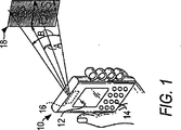
図1における参照番号10は、概略的に、携帯型機器(例えば、パーソナルデジタルアシスタント)を示しており、この携帯型機器には、例えば、図2に示されているような、軽量かつコンパクトな画像投影装置20が搭載される。また、この携帯型機器は、この機器からの可変距離の地点において、2次元カラー画像を投影するように動作可能である。例えば、画像18は、機器10に対する作動距離範囲内に配置される。
図1に示されているように、画像18は、画像の水平方向に沿って延びている光学的水平スキャンラインAの上を延びており、さらに、画像の垂直方向に沿って延びている光学的垂直スキャンラインBの上を延びている。以下に記載されるように、画像は、装置20におけるスキャナによって掃引されるスキャンラインのラスタパターン上の照明されているピクセルと照明されていないピクセルとから構成される。
As shown in FIG. 1, the
機器10の平行6面体の形状は、装置20が実装され得るハウジングのフォームファクタのうちの1つを表しているに過ぎない。この機器は、ペン、携帯電話、クラムシェル、または腕時計の形状であり得る。好適な実施形態において、装置20は、30cm3未満の体積である。このコンパクトかつ小さなサイズは、装置20が多種多様な形状、すなわち、大小の、携帯型または固定式のハウジングに搭載されることを可能にする。このハウジングは、オンボードディスプレイ12、キーパッド14、および画像を投影する窓16を有するハウジングを含んでいる。
The shape of the parallelepiped of the
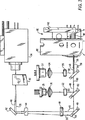
図2および図3を参照すると、装置20は、半導体レーザ22を含んでおり、これは、活性化されたときに、約635〜655ナノメートルの明るい赤色レーザを放出する。レンズ24は、正の焦点距離を有する非球面状の凸レンズであり、赤色ビームにおけるほぼ全てのエネルギーを収集し、回折が制限されたビームを生成するように動作可能である。レンズ26は、負の焦点距離を有する凹レンズである。レンズ24、26はそれぞれ、図示されていないレンズホルダによって保持されており、これらのレンズホルダは、機器10の内部のサポート(図2においては、明確化のために図示されていない)上に離れて配置されている。レンズ24、26は、作動距離にわたって赤色ビームの輪郭を整形する。
With reference to FIGS. 2 and 3, the
別の半導体レーザ28が、サポート上に搭載され、活性化されたときに、約475〜505ナノメートルの回折が制限された青色レーザビームを放出する。別の非球面状の凸レンズ30および凹レンズ32が、レンズ24、26と同様の方法で、青色ビームを整形するために、用いられる。
When another
約530ナノメートルの波長を有する緑色レーザビームは、半導体レーザによって生成されないが、代わりに、赤外線ダイオード励起YAG結晶レーザ(その出力ビームは、1060ナノメートルである)を有する緑色モジュール34によって、生成される。非線形周波数2倍化結晶が、赤外線レーザキャビティにおいて、2つのレーザミラーの間に含まれている。キャビティの内部における赤外線レーザの出力は、キャビティの外部において結合された出力よりもはるかに大きいので、周波数ダブラーは、キャビティの内部において、緑色レーザをより効率的に生成する。レーザの出力ミラーは、1060nmの赤外放射を反射可能であり、2倍化された530nmの緑色レーザビームを伝送可能である。固体レーザおよび周波数ダブラーの正確な動作は、正確な温度制御を必要とするので、Peltier効果に依存する半導体デバイスが、緑色レーザの温度を制御するために用いられる。熱電気クーラーが、印加された電流の極性に依存して、デバイスを加熱または冷却し得る。サーミスタは、緑色レーザモジュールの温度をモニタするための、緑色レーザの一部分である。サーミスタからの読取りは、コントローラに供給され、このコントローラは、熱電気クーラーに応じて調整する。
A green laser beam having a wavelength of about 530 nanometers is not generated by a semiconductor laser, but instead is generated by a
以下に記載されるように、レーザは、約100Hzの周波数でパルス発振する。赤色レーザ22および青色レーザ28は、そのような高い周波数でパルス発振し得るが、現在利用可能な緑色固体レーザは、そのように発振することができない。結果として、緑色モジュール34から放出される緑色レーザビームは、緑色ビームを回折させるために、結晶の内部に音響定常波を形成する音響光学変調器(AOM)36を用いることにより、パルス発振される。しかしながら、AOM36は、0次の回折されていないビーム38、および1次のパルス発振された回折されたビーム40を生成する。ビーム38、40は、それらを分離して、望ましくない0次のビーム38を除去するために、互いに分岐(diverge)する。また、ビーム38、40は、フォルディングミラー42を有する、長い折れ曲がった経路に沿って、ルーティングされる。代替的に、AOMは、緑色レーザをパルス発振するために、外部または内部のいずれかで、用いられ得る。緑色レーザビームを変調するためのその他の可能な方法は、電子吸収変調、またはMach−Zender干渉計を含む。AOMは、図2に概略的に示されている。
As described below, the laser pulses at a frequency of about 100 Hz. The
ビーム38、40は、正のレンズ44および負のレンズ46を介してルーティングされる。しかしながら、回折された緑色ビーム40のみが、フォルディングミラー48に衝突し、フォルディングミラー48から反射されることが可能である。回折されていないビーム38は、好適にはミラー48に搭載されている吸収体50によって吸収される。
装置は、一対の2色性フィルタ52、54を含んでおり、この一対の2色性フィルタは、緑色ビーム、青色ビーム、赤色ビームを、スキャニングアセンブリ60に到達するできるだけ前に、同一直線上に形成するように配置されている。フィルタ52は、緑色ビーム40が、フィルタ52を通ることを許容するが、青色レーザ28からの青色ビーム56は、干渉効果によって反射される。フィルタ54は、緑色ビーム40および青色ビーム56が、フィルタ54を通ることを許容するが、赤色レーザ22からの赤色ビーム58は、干渉効果によって反射される。
The apparatus includes a pair of
ほぼ同一直線上にあるビーム40、56、58は、固定式のバウンスミラー62に配向され、このバウンスミラー62から反射される。スキャニングアセンブリ60は、第1のスキャンミラー64であって、慣性駆動部66(図4〜図5において分離して示されている)によって、第1のスキャンレートで振動させられ、水平スキャン角度Aにわたって、バウンスミラー62から反射されたレーザビームを掃引する、第1のスキャンミラー64と、第2のスキャンミラー68であって、電磁駆動部70によって、第2のスキャンレートで振動させられ、垂直スキャン角度Bにわたって、第1のスキャンミラー64から反射されたレーザビームを掃引する、第2のスキャンミラー68とを含んでいる。異なる構成において、スキャンミラー64、68は、単一の2軸ミラーによって置換され得る。
The substantially
慣性駆動部66は、高速であって低電力消費型のコンポーネントである。慣性駆動部の詳細は、本出願の同一出願人によって、2003年3月13日に出願された、米国特許出願公開第10/387,878号明細書に記載されており、この米国特許出願は、参照により本明細書に援用される。以下に記載されるように、慣性駆動部の使用は、スキャニングアセンブリ60の電力消費を1ワット未満に低減させ、カラー画像を投影する場合には、10ワット未満に低減させる。
The
駆動部66は、ヒンジによってスキャンミラー64を支持するための可動フレーム74を含んでいる。このヒンジは、一対の同一直線上のヒンジ部分76、78を含んでおり、これらヒンジ部分は、ヒンジ軸に沿って延びており、スキャンミラー64の対向領域とフレームの対向領域との間に接続される。図示されているように、フレーム74は、必ずしもスキャンミラー64を囲んでいる必要はない。
The
フレーム、ヒンジ部分、およびスキャンミラーは、ワンピースの、ほぼ平面状の、厚さが約150μであるシリコン基板から製造される。このシリコン基板は、オメガ形状のスロット(上部の平行なスロット部分、下部の平行なスロット部分、および中央のU形状のスロット部分を有している)を形成するためにエッチングされる。スキャンミラー64は、好適には楕円形状を有しており、スロット部分において自由に運動することができる。好適な実施形態において、楕円形の形状のスキャンミラーの軸に沿った寸法は、749μ×1600μである。各ヒンジ部分は、幅27μ、長さ1130μである。フレームは、長方形の形状を有しており、幅3100μ、長さ4600μである。
The frame, hinge portion, and scan mirror are fabricated from a one-piece, substantially planar, silicon substrate having a thickness of about 150 microns. The silicon substrate is etched to form omega-shaped slots (having an upper parallel slot portion, a lower parallel slot portion, and a central U-shaped slot portion). The
慣性駆動部は、ほぼ平面状の印刷回路基板80に搭載され、フレームを直接的に運動させたり、慣性によって、ヒンジ軸のまわりでスキャンミラー64を間接的に振動させたりするように動作可能である。慣性駆動部の一実施形態は、一対の圧電トランスデューサ82、84を含んでおり、この一対の圧電トランスデューサは、基板80に対して垂直に延びており、ヒンジ部分76の両側におけるフレーム74の間隔を空けられた部分(spaced apart portion)と接触する。各トランスデューサの1つの端部と各フレーム部分との間の永久的な接触を保証するために、接着剤が用いられ得る。各トランスデューサの反対側の端部は、基板80の後方から突出しており、ワイヤ86、88によって、周期交流電源(図示されず)に電気的に接続される。
The inertial drive unit is mounted on the substantially planar printed
使用中、周期信号は、各トランスデューサに周期的駆動電圧を印加し、それぞれのトランスデューサの長さを交互に伸縮させる。トランスデューサ82が延びている場合、トランスデューサ84は収縮し、その逆に、トランスデューサ84が延びている場合、トランスデューサ82は収縮する。これにより、間隔を空けられたフレーム部分を同時に押したり引いたりし、フレームをヒンジ軸のまわりで捩れさせる。駆動電圧は、スキャンミラーの共振周波数に対応する周波数を有している。スキャンミラーは、初期の休止位置から運動させられ、共振周波数でヒンジ軸のまわりを振動するまで、運動させられる。好適な実施形態において、フレームおよびスキャンミラーは、約150μの厚さであり、スキャンミラーは高いQ係数を有している。各トランスデューサによる約1μの運動は、20kHz以上のスキャンレートでスキャンミラーの振動を引き起こし得る。
In use, the periodic signal applies a periodic drive voltage to each transducer and alternately stretches the length of each transducer. When the
別の一対の圧電トランスデューサ90、92は、基板80に対して垂直に延びており、ヒンジ部分78の両側におけるフレーム74の間隔を空けられた部分と永久的に接触する。トランスデューサ90、92は、フィードバックデバイスとして機能することにより、フレームの振動運動をモニタし、ワイヤ94、96を介することにより、電気的フィードバック信号を、フィードバック制御回路(図示されず)に導く。
Another pair of
代替的に、フィードバックのために、圧電トランスデューサ90、92を用いる代わりに、磁気的なフィードバックが用いられ得る。ここで、磁石は、高速ミラーの背後に搭載され、振動する磁石によって生成された変化する磁場をピックアップするために、外部コイルが用いられる。
Alternatively, instead of using the
光がスキャンミラーの外表面から反射され得るが、ミラー64の表面を、金、銀、アルミニウムから構成された鏡面反射コーティング、または特別に設計された高い反射性の誘電性のコーティングを用いることによって、コーティングすることが望ましい。
Although light can be reflected from the outer surface of the scan mirror, the surface of the
電磁駆動部70(図8において分離して示されている)は、第2のスキャンミラー68の背後に一緒に搭載されている永久磁石200(図9参照)と、周期的な駆動信号に応答して、周期的な磁場を生成するように動作可能な電磁駆動コイル72とを含んでいる。周期的な磁場が、磁石の永久磁場と磁気的に相互作用し、磁石および第2のスキャンミラー68を振動させることができるように、駆動コイル72は、磁石200に隣接している。
An electromagnetic drive 70 (shown separately in FIG. 8) is responsive to a permanent magnet 200 (see FIG. 9) mounted together behind the
慣性駆動部66は、好適には5kHz以上、より好適には約18kHz以上の高速のスキャンレートで、スキャンミラー64を振動させる。この高速スキャンレートは、不可聴周波数なので、ノイズおよび振動を最小化する。電磁駆動部70は、約40Hzの低速のスキャンレートで、スキャンミラー68を振動させる。この低速のスキャンレートは、過剰なフリッカを有さずに画像が人間の目の網膜に残存することを可能にするためには、十分速いスキャンレートである。
The
高速ミラー64が水平スキャンラインを掃引し、低速ミラー68が水平スキャンラインを垂直に掃引することにより、ラスタパターンを形成する。このラスタパターンは、画像を構成するほぼ平行なスキャンラインのグリッドまたは系列である。各スキャンラインは、多数のピクセルを有している。画像の解像度は、好適には、1024×768ピクセルのXGA品質である。制限された作動範囲にわたって、高精細度のテレビ標準規格、すなわち、720p、1270×720ピクセルで表示することができる。一部のアプリケーションにおいて、この1/2の320×480ピクセルのVGA品質、またはこの1/4の320×240ピクセルのVGA品質で十分である。最小でも、160×160ピクセルの解像度が所望される。
The high-
ミラー64、68の役割は、ミラー68が高速、ミラー64が低速というように、入れ替えられ得る。ミラー64はまた、垂直スキャンラインを掃引するように設計され得、この掃引事象において、ミラー68は、水平スキャンラインを掃引し得る。また、慣性駆動部は、ミラー68を駆動させるために用いられ得る。特に、ミラーは、電気機械的駆動部、電気的駆動部、機械的駆動部、静電気的駆動部、磁気的駆動部、または電磁気的駆動部のうちのいずれかによって駆動され得る。
The roles of the
低速ミラーは、画像が表示される間に、一定速度の掃引モードで動作する。ミラーの戻りの間に、このミラーは、かなり高い固有周波数で、最初の位置を掃引する。ミラーの戻り動程の間に、レーザは、デバイスの電力消費を低減させるために、オフにされ得る。 The slow mirror operates in a constant speed sweep mode while an image is displayed. During the mirror return, this mirror sweeps the initial position at a fairly high natural frequency. During the mirror return stroke, the laser may be turned off to reduce the power consumption of the device.
図6は、図2と同じ視点による、装置20の実際の実装である。上述のコンポーネントは、トップカバー100およびサポート平面102を含むサポートに搭載されている。ホルダ104、106、108、110、112のそれぞれは、フォルディングミラー42、48、およびフィルタ52、54、およびバウンスミラー62を、共通の配列(alignment)に保持している。各ホルダは、サポートに固定するように搭載された配置ポストを受け入れるための、複数の配置スロットを有している。このようにして、ミラーおよびホルダが、正確に配置される。示されているように、3つのポストが存在しているので、2つの角度調整と、1つの横方向の調整とが可能である。各ホルダは、その最終的な位置に接着され得る。
FIG. 6 is an actual implementation of the
画像は、スキャンラインにおける1つ以上のピクセルの選択的な照明によって構成される。図7を参照して以下に詳細に記載されるように、コントローラ114は、3つのレーザビームによって、ラスタパターンにおける選択されたピクセルを照明させ、可視状態にする。例えば、赤色電力コントローラ116、青色電力コントローラ118、および緑色電力コントローラ120のそれぞれは、赤色レーザ22、青色レーザ28、および緑色レーザ34に電流を導くことにより、これらレーザを活性化することによって、選択されたピクセルの各々において、それぞれの光ビームを放出すること、ならびに赤色レーザ、青色レーザ、および緑色レーザに電流を導かないことにより、これらレーザを不活性化することによって、選択されていないその他のピクセルを照明しないことが可能である。照明されたピクセルおよび照明されていないピクセルの結果として得られたパターンは、人間または機械によって読取り可能な情報またはグラフィックに関する任意の表示であり得る画像を含んでいる。
The image is constructed by selective illumination of one or more pixels in the scan line. As described in detail below with reference to FIG. 7, the
図1を参照すると、ラスタパターンが、拡大図で示されている。レーザビームは、ある端点から開始して、慣性駆動部によって、水平方向に沿って、所定の水平スキャンレートで、反対の端点まで掃引され、スキャンラインを形成する。その後、レーザビームは、電磁駆動部70によって、垂直方向に沿って、所定の垂直スキャンレートで、別の端点まで掃引され、第2のスキャンラインを形成する。その後のスキャンラインの形成は、同じ方法で行われる。
Referring to FIG. 1, the raster pattern is shown in an enlarged view. The laser beam starts from one end point and is swept by the inertial drive unit along the horizontal direction at a predetermined horizontal scan rate to the opposite end point to form a scan line. Thereafter, the laser beam is swept up to another end point along the vertical direction at a predetermined vertical scan rate by the
マイクロプロセッサ114または制御回路の制御のもとで、電力コントローラ116、118、120の動作によって、レーザを活性化するか、またはレーザを選択された回数だけオンおよびオフにパルス発振することにより、ラスタパターンに画像が形成される。所望の画像におけるピクセルが可視であることが所望されるときにのみ、レーザは、可視光を生成して、オンにされる。各ピクセルの色は、ビームの1つ以上の色によって決定される。可視光のスペクトルにおける任意の色は、赤色レーザ、青色レーザ、および緑色レーザを選択的に重ね合わせることにより、形成され得る。ラスタパターンは、各ライン上の複数のピクセルおよび複数のラインから構成されるグリッドである。画像は、選択されたピクセルのビットマップである。全ての文字または数字、任意のグラフィカルデザインまたはロゴ、および機械読取り可能なバーコード記号さえも、ビットマップ画像として形成され得る。
Under the control of the
図7に示されているように、入ってくるビデオ信号は、垂直同期化データおよび水平同期化データならびにピクセルデータおよびクロックデータを有しており、マイクロプロセッサ144の制御のもとで、赤色バッファ122、青色バッファ124、および緑色バッファ126に送信される。1つのフルVGAフレームの格納は、多くのキロバイトを必要とし、1つのフレームが書き込まれている間に、別のフレームが処置および投影されることを可能にするために、バッファにおいて、2つのフルフレームのために十分なメモリを有していることが望ましい。バッファされたデータは、速度プロファイラ130の制御のもとで、フォーマッタ128、および赤色ルックアップテーブル(LUT)132、青色ルックアップテーブル(LUT)134、緑色ルックアップテーブル(LUT)136に送信され、スキャニングによって引き起こされた固有の内部歪み、および投影された画像の表示角度によって引き起こされた幾何学的歪みを補正する。結果として得られた赤色デジタル信号、青色デジタル信号、および緑色デジタル信号は、デジタルアナログ変換器(DAC)138、140、142によって、赤色アナログ信号、青色アナログ信号、および緑色アナログ信号に変換される。赤色アナログ信号および青色アナログ信号は、赤色レーザデバイス(LD)144および青色レーザデバイス(LD)146に供給され、これらはまた、赤色コントローラ116および青色コントローラ118にも接続されている。緑色アナログ信号は、AOM無線周波数(RF)ドライバ150に、そして次に緑色レーザ34に供給され、これはまた、緑色LD148に、そして緑色電力コントローラ120にも接続されている。
As shown in FIG. 7, the incoming video signal has vertical and horizontal synchronization data as well as pixel data and clock data, and under the control of the
フィードバック制御もまた、図7に示されており、赤色アナログデジタル(A/D)変換器158、青色アナログデジタル(A/D)変換器160、緑色アナログデジタル(A/D)変換器162、そしてマイクロコントローラ114に接続された、赤色フォトダイオード増幅器152、青色フォトダイオード増幅器154、および緑色フォトダイオード増幅器156を含んでいる。A/D変換器166、そしてマイクロプロセッサに接続されたサーミスタ増幅器164によって、熱がモニタされる。
Feedback control is also shown in FIG. 7 and includes a red analog to digital (A / D) converter 158, a blue analog to digital (A / D)
スキャンミラー64、68は、ドライバ168、170によって駆動され、これらには、DAC172、174からのアナログ駆動信号が供給される。上記DAC172、174は、マイクロコントローラに接続されている。フィードバック増幅器176、178は、スキャンミラー64、68の位置を検出し、フィードバックA/D180、182、そしてマイクロプロセッサに接続されている。
The scan mirrors 64 and 68 are driven by
電力管理回路184は、電力を最小化する一方で、好適には、緑色レーザを常にオンに維持し、赤色レーザおよび青色レーザの電流をレージング閾値未満に維持することによって、高速オンタイム(fast on−times)を可能にするように、動作可能である。
The
レーザ安全停止回路186は、スキャンミラー64、68のいずれか一方が、適切な場所から外れていることを検出された場合に、レーザをオフにするように動作可能である。
The laser
再び図8〜図9を参照すると、永久磁石200およびスキャンミラー68を振動させるための電磁駆動部70は、上部支持部202、下部支持部204、およびボビン206を含んでおり、このボビンのまわりには、駆動コイル72が巻かれている。駆動コイル72が周期的な駆動信号によって活性化されるときに、駆動コイルは、交流磁場を生成し、これは、磁石の永久磁場と相互作用することによって、磁石200およびミラー68を振動させる。上部支持部202は、磁石を駆動コイルの付近に移動させるための、凹部208を有している。
Referring again to FIGS. 8 to 9, the
上述のように、スキャンミラー64の位置および運動をモニタするだけではなく、スキャンミラー68の位置および運動をもモニタすることが望ましい。このために、第1のフィードバックコイル210が、磁石200の付近で、ボビン206に巻かれており、磁石200およびミラー68の一緒の運動を表している、第1のフィードバック信号を生成する。しかしながら、第1のフィードバックコイル210はまた、駆動コイル72の付近にも存在している。駆動コイルと第1のフィードバックコイルとの間には、望ましくない磁気結合(変圧器のフィードスルーまたはクロストークとも称される)が存在しており、これは、第1のフィードバック信号を劣化させる。
As described above, it is desirable to monitor not only the position and movement of the
そのようなクロストークを、除去できないにしても、低減させるために、第2のフィードバックコイル212がボビン206のまわりに巻かれ、第1のフィードバックコイル210と比べて、磁石200から離れて配置される。図9に示されているように、第2のコイル212は、軸まわりに、第1のコイル210よりも磁石から離れて配置されている。第2のコイル212は、第2のフィードバック信号を生成するが、第2のコイルは第1のコイルよりも離れた位置にあるので、第2のフィードバック信号は、第1のフィードバック信号よりも弱い。第2のコイルはまた、駆動コイル72の付近に配置されており、駆動コイルからの同じクロストークによって、劣化させられる。
In order to reduce such crosstalk even if it cannot be removed, a
本発明にしたがうと、第1のフィードバック信号および第2のフィードバック信号は、第1のフィードバック信号からクロストークを除去することによって、クロストークが低減されたフィードバック信号(これは、スキャンミラー68の運動を正確に表している)を生成するために、処理される。このクロストークが低減された信号は、フィードバック増幅器178に導かれ、フィードバックA/D 182において、デジタル信号に変換され、マイクロコントローラ114に導かれる。そのような処理は、第1のフィードバック信号から第2のフィードバック信号を減算することにより、両方のフィードバック信号における同じクロストークを相殺することを含んでいる。そのような減算は、コンパレータを介して、両方のフィードバック信号を供給することによって実行されるか、または電子的な反転(electronic inversion)によって実行される。電子的な反転は、好適には、図10に示されているようなものであり、ここでは、第1のフィードバックコイル210が、第1の円周方向(例えば、時計まわり)に巻かれ、第2のフィードバックコイル212が、反対の円周方向(例えば、反時計まわり)に巻かれ、フィードバックコイル210、212は、直列に電気的に接続されている。クロストークが低減されたフィードバック信号は、出力端子1、4に現れる。駆動コイル72に対する周期的な駆動信号は、入力端子2,3に現れる。
In accordance with the present invention, the first feedback signal and the second feedback signal are reduced in crosstalk by removing the crosstalk from the first feedback signal (this is the motion of the scan mirror 68). Is accurately processed). The signal with reduced crosstalk is guided to the feedback amplifier 178, converted to a digital signal by the feedback A /
2つのフィードバックコイルを用いると、電気的なノイズを除去することができるだけではなく、その他の形態のノイズをも低減させることができる。例えば、スキャンミラー68が、外部の衝撃または振動を受けるとき、これらの力は磁石に伝わり、その後、これらの力は両方のフィードバックコイルによって感知される。
Using two feedback coils can not only eliminate electrical noise, but also reduce other forms of noise. For example, when the
本発明は、上述のように、画像投影システムにおけるスキャンミラーの運動をモニタすることのみには限定されず、図11に示されているタイプの電気光学的な読み取り機220においても用いられ得る。この電気光学的読み取り機220は、作動距離内に配置されたインディシア(例えば、バーコードシンボル224)を電気光学的に読み取るための読み取り機である。読み取り機220は、ピストルグリップハンドル221と、手動作動式トリガ222とを有しており、このトリガ222は、押されたときに、光ビーム223がシンボル224に配向されることを可能にする。読み取り機220は、ハウジング225を含んでおり、このハウジング225においては、光源226、光検出器227、信号処理回路228、およびバッテリーパック229が収容されている。ハウジングの前面における光透過性の窓230は、光ビーム223がハウジングから放出されることを可能にし、光231がシンボルから散乱されて、ハウジングに入ることを可能にする。アクセスを容易にするために、有利にも、キーボード232およびディスプレイ233が、ハウジングの上壁(top wall)に提供され得る。
As described above, the present invention is not limited to only monitoring the movement of the scan mirror in the image projection system, but can also be used in an electro-
使用中に、ハンドル221を保持しているオペレータは、ハウジングをシンボルに向けて照準を合わせ、トリガを押す。光源226は、光ビームを放出し、これは、光学的に変化させられ、光学的焦点調節アセンブリ235によって焦点を合わせられ、シンボル224上にビームスポットを形成する。ビームは、ビームスプリッタ234からスキャンミラー236に送られ、このスキャンミラー236は、モータ駆動部238によって、1秒当たり少なくとも20スキャンのスキャンレートで振動する。スキャンミラー236は、このスキャンミラー236に入射するビームをシンボル224へと反射し、シンボルにわたるスキャンにおいて、所定のスキャンパターンでビームスポットを掃引する。スキャンパターンは、いくつかの例を挙げると、スキャン方向に沿う、シンボルに沿って縦方向に延びているスキャンラインであるか、または互いに直交する方向に沿って配置された一連のスキャンラインであるか、または全方向性のパターン(omnidirectional pattern)であり得る。
In use, the operator holding the
反射された光231は、スキャンパターンにわたって可変輝度を有しており、窓230を通り、スキャンミラー236に送られる。このスキャンミラー236において、光231は、スプリッタ234へと反射させられ、さらに、アナログ電気信号を変換するための光検出器227へと反射させられる。信号処理回路228は、信号をデジタル化およびデコードすることにより、シンボルにおけるエンコードされたデータを抽出する。
The reflected
駆動モータ238は、図12において、駆動コイル240および第1のフィードバックコイル242(両方とも共通のボビンに巻かれている)を有するものとして、より詳細に示されている。信号処理回路228は、駆動回路244に制御信号を送信するように動作可能な制御回路246を含んでおり、次にこの駆動回路244は、永久磁石(図示されず)と相互作用する電磁場を生成し、モータ238を駆動させるために、駆動コイル240に駆動信号を送信する。
The
上述のように、第1のフィードバックコイル242もまた、磁石と相互作用し、駆動信号と同じ周波数の、様々な目的に有用な電気的フィードバック信号を生成する。例えば、駆動回路244は、駆動コイルに供給された駆動信号の振幅を調整するために、閉ループ回路において、エラー比較器を含んでいる。また、フィードバック信号は、上述のSOS信号を導出するために用いられ、これは、スキャンラインの同期化のために、マイクロプロセッサに供給される。加えて、フィードバック信号は、駆動部の故障をモニタするために用いられる。
As described above, the
本発明の1つの特徴にしたがうと、第2のフィードバックコイル248をモータ238上に配置することが目的である。上述のように、両方のコイル242、248は、駆動コイル240との電磁結合によって、同じ程度、品質が劣化する。フィードバックコイル242、248のそれぞれによって生成されたフィードバック信号を減算することにより、クロストークが除去される。
In accordance with one aspect of the present invention, it is an object to place the
新規であって、特許証によって保護されることが望まれるものとして請求されている内容は、請求の範囲に述べられている。 What is claimed as new and desired to be protected by Letters Patent is set forth in the appended claims.
Claims (4)
永久磁石および活性化可能な駆動コイルを含む駆動部であって、該永久磁石は、永久磁場を有しており、該ミラーと一緒に運動させるために該ミラー上に搭載されており、該活性化可能な駆動コイルは、周期的な駆動信号によって活性化されたときに、該磁石の該永久磁場と相互作用する電磁場を生成し、該ミラーおよび該磁石を一緒に運動させる、駆動部と、
該ミラーおよび該磁石の一緒の運動を表している第1のフィードバック信号を生成するための、該磁石と電磁気的な関係にある第1のフィードバックコイルであって、該第1のフィードバックコイルはまた、該駆動コイルと電磁気的な関係にあり、該第1のフィードバックコイルはまた、該駆動信号とのクロストークによって劣化されている、第1のフィードバックコイルと、
該第1のフィードバックコイルと比べて該磁石から離れて配置されている第2のフィードバックコイルであって、該第2のフィードバックコイルは、該第1のフィードバック信号よりも弱い第2のフィードバック信号を生成するように動作可能であり、該第2のフィードバック信号もまた、該ミラーおよび該磁石の一緒の運動を表しており、該第2のフィードバックコイルはまた、該駆動コイルと電磁気的な関係にあり、該第2のフィードバックコイルはまた、該駆動信号とのクロストークによって劣化されている、第2のフィードバックコイルと、
該フィードバック信号を処理するための手段であって、該第1のフィードバック信号から該クロストークを除去することにより、該スキャンミラーの運動を表している、クロストークが低減されたフィードバック信号を生成する手段と
を備えており、該処理手段は、該第1のフィードバック信号からの該第2のフィードバック信号の減算を含んでいる、装置。A device for monitoring the movement of a scan mirror,
A driving unit including a permanent magnet and activatable driving coil, the permanent magnet has a permanent magnetic field, is mounted on the mirror in order to exercise together with the mirror, the active the reduction can drive coil, when activated by a periodic drive signal, to produce the permanent magnetic and electromagnetic fields interacting of the magnet causes movement the mirror and the magnet together, a driving unit,
A first feedback coil in electromagnetic relationship with the magnet for generating a first feedback signal representative of the movement of the mirror and the magnet together, the first feedback coil also being , located in the drive coil and the electromagnetic relationship, said first feedback coil also is degraded by crosstalk with the drive signal, a first feedback coil,
A second feedback coil as compared with the first feedback coil is located away from the magnet, the feedback coil of said second, weak second feedback signal than the first feedback signal The second feedback signal is also representative of the movement of the mirror and the magnet together, and the second feedback coil is also in electromagnetic relationship with the drive coil. There, the feedback coil of the second is also degraded by crosstalk between the drive signal and the second feedback coil,
Means for processing the feedback signal, wherein the crosstalk is removed from the first feedback signal to generate a crosstalk-reduced feedback signal that represents motion of the scan mirror. that includes a manual stage, the processing means includes a subtraction of the second feedback signal from the first feedback signal, device.
Applications Claiming Priority (2)
| Application Number | Priority Date | Filing Date | Title |
|---|---|---|---|
| US11/116,642 US7497578B2 (en) | 2005-04-28 | 2005-04-28 | Monitoring scan mirror motion in electro-optical readers and image projectors |
| PCT/US2006/015506 WO2006116330A2 (en) | 2005-04-28 | 2006-04-20 | Monitoring scan mirror motion in electro-optical readers and image projectors |
Publications (3)
| Publication Number | Publication Date |
|---|---|
| JP2008539465A JP2008539465A (en) | 2008-11-13 |
| JP2008539465A5 JP2008539465A5 (en) | 2009-04-02 |
| JP4681045B2 true JP4681045B2 (en) | 2011-05-11 |
Family
ID=37215379
Family Applications (1)
| Application Number | Title | Priority Date | Filing Date |
|---|---|---|---|
| JP2008509015A Expired - Fee Related JP4681045B2 (en) | 2005-04-28 | 2006-04-20 | Monitoring scan mirror motion in electro-optic readers and image projectors |
Country Status (5)
| Country | Link |
|---|---|
| US (1) | US7497578B2 (en) |
| JP (1) | JP4681045B2 (en) |
| CN (1) | CN101529331B (en) |
| DE (1) | DE112006001080T5 (en) |
| WO (1) | WO2006116330A2 (en) |
Families Citing this family (9)
| Publication number | Priority date | Publication date | Assignee | Title |
|---|---|---|---|---|
| US8520836B2 (en) * | 2006-07-24 | 2013-08-27 | Plantronics, Inc. | Projection headset |
| JP5646148B2 (en) * | 2009-04-07 | 2014-12-24 | 船井電機株式会社 | projector |
| US20110211169A1 (en) * | 2010-03-01 | 2011-09-01 | Osram Opto Semiconductor Gmbh | Projection System |
| GB2485237A (en) | 2010-11-08 | 2012-05-09 | Nec Corp | MBMS provided by unicast or broadcast/multicast in dependence on the number of interested users. |
| TWI438488B (en) | 2010-12-17 | 2014-05-21 | Ind Tech Res Inst | Optical scanning projection system |
| US9197790B2 (en) | 2012-01-13 | 2015-11-24 | Industrial Technology Research Institute | Optical scanning projection module |
| EP2708308A1 (en) * | 2012-09-14 | 2014-03-19 | Trumpf Laser Marking Systems AG | Laser processing device |
| CN104097214B (en) * | 2013-04-02 | 2016-12-28 | 苏州科瓴精密机械科技有限公司 | A kind of automatic robot |
| DE102017002866A1 (en) * | 2017-03-24 | 2018-09-27 | Blickfeld GmbH | Scanner with two sequential scan units |
Family Cites Families (6)
| Publication number | Priority date | Publication date | Assignee | Title |
|---|---|---|---|---|
| US5280377A (en) * | 1991-06-28 | 1994-01-18 | Eastman Kodak Company | Beam scanning galvanometer with spring supported mirror |
| US5280163A (en) * | 1992-06-26 | 1994-01-18 | Symbol Technologies, Inc. | Drive circuit for resonant motors |
| CN1053052C (en) * | 1992-12-23 | 2000-05-31 | 欧林巴斯光学工业股份有限公司 | Laser scanning device with automatic range and spot size adjustment |
| JP2003043401A (en) * | 2001-07-27 | 2003-02-13 | Olympus Optical Co Ltd | Optical scanner driving circuit |
| US7182263B2 (en) * | 2004-09-30 | 2007-02-27 | Symbol Technologies, Inc. | Monitoring light beam position in electro-optical readers and image projectors |
| US7521279B2 (en) * | 2005-02-18 | 2009-04-21 | Symbol Technologies, Inc. | Image projection at different image planes |
-
2005
- 2005-04-28 US US11/116,642 patent/US7497578B2/en not_active Expired - Fee Related
-
2006
- 2006-04-20 CN CN2006800199377A patent/CN101529331B/en not_active Expired - Fee Related
- 2006-04-20 DE DE112006001080T patent/DE112006001080T5/en not_active Withdrawn
- 2006-04-20 WO PCT/US2006/015506 patent/WO2006116330A2/en active Application Filing
- 2006-04-20 JP JP2008509015A patent/JP4681045B2/en not_active Expired - Fee Related
Also Published As
| Publication number | Publication date |
|---|---|
| JP2008539465A (en) | 2008-11-13 |
| CN101529331A (en) | 2009-09-09 |
| US20060244924A1 (en) | 2006-11-02 |
| US7497578B2 (en) | 2009-03-03 |
| DE112006001080T5 (en) | 2008-03-13 |
| CN101529331B (en) | 2010-07-21 |
| WO2006116330A3 (en) | 2009-04-23 |
| WO2006116330A2 (en) | 2006-11-02 |
Similar Documents
| Publication | Publication Date | Title |
|---|---|---|
| US7367682B2 (en) | Color image projection arrangement and method | |
| US7859600B2 (en) | Arrangement for and method of projecting a level image | |
| JP4681045B2 (en) | Monitoring scan mirror motion in electro-optic readers and image projectors | |
| JP4671443B2 (en) | System and method for projecting a color image | |
| JP5213251B2 (en) | Correction for image distortion in image projectors | |
| JP5392894B2 (en) | A device that synchronizes the data signal with the movement of the scan mirror on the pattern | |
| US7312911B2 (en) | Arrangement for and method of improving image quality, especially for image projection arrangements | |
| US7352499B2 (en) | Arrangement for and method of projecting an image with pixel mapping | |
| EP2035893B1 (en) | Arrangement for and method of projecting an image with safety circuitry | |
| KR101020072B1 (en) | Arrangement for and method of projecting an image with linear scan lines | |
| JP2009510518A (en) | Color image projection apparatus and method using electroabsorption modulation type green laser system | |
| US7815119B2 (en) | Monitoring scan mirror motion in laser scanning arrangements | |
| US7460287B2 (en) | Arrangement for and method of increasing pixel symmetry, especially for image projection arrangements | |
| KR20090010096A (en) | Arrangement for and method of projecting an image to be viewed over extended viewing range | |
| US20070279509A1 (en) | Arrangement for and method of projecting an image with modulated lasers | |
| US20080204541A1 (en) | Aperture stop in an image projection arrangement for preserving color fidelity over an image |
Legal Events
| Date | Code | Title | Description |
|---|---|---|---|
| A521 | Written amendment |
Free format text: JAPANESE INTERMEDIATE CODE: A523 Effective date: 20090205 |
|
| A621 | Written request for application examination |
Free format text: JAPANESE INTERMEDIATE CODE: A621 Effective date: 20090205 |
|
| A977 | Report on retrieval |
Free format text: JAPANESE INTERMEDIATE CODE: A971007 Effective date: 20101111 |
|
| A131 | Notification of reasons for refusal |
Free format text: JAPANESE INTERMEDIATE CODE: A131 Effective date: 20101116 |
|
| A521 | Written amendment |
Free format text: JAPANESE INTERMEDIATE CODE: A523 Effective date: 20101214 |
|
| A711 | Notification of change in applicant |
Free format text: JAPANESE INTERMEDIATE CODE: A711 Effective date: 20110107 |
|
| TRDD | Decision of grant or rejection written | ||
| A01 | Written decision to grant a patent or to grant a registration (utility model) |
Free format text: JAPANESE INTERMEDIATE CODE: A01 Effective date: 20110131 |
|
| A01 | Written decision to grant a patent or to grant a registration (utility model) |
Free format text: JAPANESE INTERMEDIATE CODE: A01 |
|
| A61 | First payment of annual fees (during grant procedure) |
Free format text: JAPANESE INTERMEDIATE CODE: A61 Effective date: 20110203 |
|
| R150 | Certificate of patent or registration of utility model |
Free format text: JAPANESE INTERMEDIATE CODE: R150 |
|
| FPAY | Renewal fee payment (event date is renewal date of database) |
Free format text: PAYMENT UNTIL: 20140210 Year of fee payment: 3 |
|
| LAPS | Cancellation because of no payment of annual fees |