JP4680792B2 - Spark plug - Google Patents
Spark plug Download PDFInfo
- Publication number
- JP4680792B2 JP4680792B2 JP2006037386A JP2006037386A JP4680792B2 JP 4680792 B2 JP4680792 B2 JP 4680792B2 JP 2006037386 A JP2006037386 A JP 2006037386A JP 2006037386 A JP2006037386 A JP 2006037386A JP 4680792 B2 JP4680792 B2 JP 4680792B2
- Authority
- JP
- Japan
- Prior art keywords
- metal shell
- insulator
- axis
- ground electrode
- end surface
- Prior art date
- Legal status (The legal status is an assumption and is not a legal conclusion. Google has not performed a legal analysis and makes no representation as to the accuracy of the status listed.)
- Active
Links
- 229910052751 metal Inorganic materials 0.000 claims description 220
- 239000002184 metal Substances 0.000 claims description 220
- 239000012212 insulator Substances 0.000 claims description 178
- 230000002093 peripheral effect Effects 0.000 claims description 123
- 238000003466 welding Methods 0.000 claims description 23
- 230000015572 biosynthetic process Effects 0.000 claims description 2
- 230000001154 acute effect Effects 0.000 claims 2
- 230000005684 electric field Effects 0.000 description 23
- 229910000510 noble metal Inorganic materials 0.000 description 12
- 238000002485 combustion reaction Methods 0.000 description 8
- 238000004519 manufacturing process Methods 0.000 description 7
- 238000000034 method Methods 0.000 description 7
- 230000007423 decrease Effects 0.000 description 5
- 238000009413 insulation Methods 0.000 description 5
- 238000012360 testing method Methods 0.000 description 5
- PXHVJJICTQNCMI-UHFFFAOYSA-N Nickel Chemical compound [Ni] PXHVJJICTQNCMI-UHFFFAOYSA-N 0.000 description 4
- 238000013459 approach Methods 0.000 description 4
- 238000002788 crimping Methods 0.000 description 4
- 238000011156 evaluation Methods 0.000 description 4
- 238000012856 packing Methods 0.000 description 4
- 239000000454 talc Substances 0.000 description 4
- 229910052623 talc Inorganic materials 0.000 description 4
- OKTJSMMVPCPJKN-UHFFFAOYSA-N Carbon Chemical compound [C] OKTJSMMVPCPJKN-UHFFFAOYSA-N 0.000 description 3
- 229910052799 carbon Inorganic materials 0.000 description 3
- 230000015556 catabolic process Effects 0.000 description 3
- 230000000694 effects Effects 0.000 description 3
- 239000000446 fuel Substances 0.000 description 3
- NJPPVKZQTLUDBO-UHFFFAOYSA-N novaluron Chemical compound C1=C(Cl)C(OC(F)(F)C(OC(F)(F)F)F)=CC=C1NC(=O)NC(=O)C1=C(F)C=CC=C1F NJPPVKZQTLUDBO-UHFFFAOYSA-N 0.000 description 3
- XEEYBQQBJWHFJM-UHFFFAOYSA-N Iron Chemical compound [Fe] XEEYBQQBJWHFJM-UHFFFAOYSA-N 0.000 description 2
- 229910045601 alloy Inorganic materials 0.000 description 2
- 239000000956 alloy Substances 0.000 description 2
- 229910001026 inconel Inorganic materials 0.000 description 2
- 229910052759 nickel Inorganic materials 0.000 description 2
- RYGMFSIKBFXOCR-UHFFFAOYSA-N Copper Chemical compound [Cu] RYGMFSIKBFXOCR-UHFFFAOYSA-N 0.000 description 1
- PNEYBMLMFCGWSK-UHFFFAOYSA-N aluminium oxide Inorganic materials [O-2].[O-2].[O-2].[Al+3].[Al+3] PNEYBMLMFCGWSK-UHFFFAOYSA-N 0.000 description 1
- 238000000889 atomisation Methods 0.000 description 1
- 239000000919 ceramic Substances 0.000 description 1
- 239000000567 combustion gas Substances 0.000 description 1
- 230000000052 comparative effect Effects 0.000 description 1
- 239000012141 concentrate Substances 0.000 description 1
- 229910052802 copper Inorganic materials 0.000 description 1
- 239000010949 copper Substances 0.000 description 1
- 238000005260 corrosion Methods 0.000 description 1
- 230000007797 corrosion Effects 0.000 description 1
- 238000013461 design Methods 0.000 description 1
- 238000010586 diagram Methods 0.000 description 1
- 238000006073 displacement reaction Methods 0.000 description 1
- 238000010304 firing Methods 0.000 description 1
- 239000008246 gaseous mixture Substances 0.000 description 1
- 230000012447 hatching Effects 0.000 description 1
- 238000003780 insertion Methods 0.000 description 1
- 230000037431 insertion Effects 0.000 description 1
- 229910052742 iron Inorganic materials 0.000 description 1
- 238000005304 joining Methods 0.000 description 1
- 239000000463 material Substances 0.000 description 1
- 239000000203 mixture Substances 0.000 description 1
- 239000000843 powder Substances 0.000 description 1
Images


Description
本発明は、横飛火を防止することができる内燃機関用のスパークプラグに関するものである。 The present invention relates to a spark plug for an internal combustion engine that can prevent side fire.
従来、内燃機関には点火のためのスパークプラグが用いられている。このスパークプラグでは、一般的には、中心電極が挿設された絶縁碍子を保持する主体金具の燃焼室側の先端部に接地電極を溶接して、接地電極の他端部を中心電極の先端部の先端面と対向させて、火花放電ギャップを形成している。そして、中心電極と接地電極との間で火花放電が行われ、両電極間に曝された混合気に着火することにより、火炎核が形成される(例えば特許文献1参照。)。 Conventionally, spark plugs for ignition are used in internal combustion engines. In this spark plug, generally, a ground electrode is welded to the tip of the metal shell that holds the insulator in which the center electrode is inserted, and the other end of the ground electrode is connected to the tip of the center electrode. A spark discharge gap is formed so as to face the tip surface of the portion. And a spark discharge is performed between a center electrode and a ground electrode, and a flame nucleus is formed by igniting the air-fuel | gaseous mixture exposed between both electrodes (for example, refer patent document 1).
内燃機関の運転時に、気筒内に濃い混合気が連続的に誘導された場合や長時間低速で運転した場合には、燃料の霧化が十分でなかったり絶縁碍子の温度が低下する等の理由で、カーボンが中心電極の周囲の絶縁碍子表面に付着する、いわゆる「くすぶり(くすぶり汚損)」が発生する。くすぶりが発生した場合、絶縁碍子の表面に付着したカーボンを通じて電流が流れ、絶縁碍子の表面と主体金具の内周面との間で横飛火が発生する場合がある。横飛火の発生を防止するには、くすぶりが発生した場合でも火花放電ギャップにおいて火花放電が行われるように、絶縁碍子の外周面と主体金具の内周面との間のクリアランスの大きさや、火花放電ギャップの大きさを規定することが有効である。
しかしながら、近年、自動車エンジンの高出力化や省燃費化が進み、エンジン側の設計の自由度の確保の点からスパークプラグの小型化が求められている。これに伴い絶縁碍子の外周面と主体金具の内周面との間のクリアランスも狭くなり、従来よりも低い電位差で横飛火が生じやすくなっている。特に、主体金具の先端面から突設された接地電極の周囲では電界強度が高くなっているため、従来のスパークプラグの各部品の寸法をそのまま小型化しただけのスパークプラグでは、くすぶりが発生した際に、接地電極の設けられた側の主体金具の内周面に対し絶縁碍子の外周面から火花放電が発生しやすくなるという問題があった。 However, in recent years, the output of automobile engines has been increased and fuel consumption has been reduced, and a reduction in the size of the spark plug has been demanded from the viewpoint of ensuring the degree of freedom in design on the engine side. Along with this, the clearance between the outer peripheral surface of the insulator and the inner peripheral surface of the metal shell is also narrowed, and side-fire is likely to occur with a lower potential difference than in the prior art. In particular, since the electric field strength is high around the ground electrode projecting from the front end surface of the metal shell, smoldering occurred in the spark plug in which the dimensions of each part of the conventional spark plug were simply reduced. At this time, there has been a problem that spark discharge tends to occur from the outer peripheral surface of the insulator with respect to the inner peripheral surface of the metal shell on the side where the ground electrode is provided.
本発明は上記問題点を解決するためになされたものであり、主体金具の内周面と絶縁碍子の外周面とを同心円からずらして配置することで横飛火の発生を防止することができるスパークプラグを提供することを目的とする。 The present invention has been made in order to solve the above-described problems, and a spark capable of preventing the occurrence of side fire by disposing the inner peripheral surface of the metal shell and the outer peripheral surface of the insulator from a concentric circle. The purpose is to provide a plug.
上記目的を達成するために、請求項1に係る発明のスパークプラグは、中心電極と、前記中心電極の軸線方向に延びる軸孔を有し、その軸孔の内部で前記中心電極を保持する絶縁碍子と、前記絶縁碍子の径方向周囲を取り囲み、前記絶縁碍子を保持する筒状の主体金具と、一端側の端面が前記主体金具の先端面に接合され、他端が前記中心電極と対向するように曲折された金属線材からなる接地電極とを備えたスパークプラグであって、前記主体金具先端面の内周側の円の中心点と、前記接地電極の前記一端側の端面の中心とを結ぶ直線上の距離において、前記接地電極の位置する側における、前記主体金具先端面を含む平面上での前記絶縁碍子の断面の外周面もしくはその平面に投影した前記絶縁碍子の外周面と、前記主体金具先端面の内周側の円との間の距離をAとし、前記接地電極の位置する側と反対側における、前記主体金具先端面を含む平面上での前記絶縁碍子の断面の外周面もしくはその平面に投影した前記絶縁碍子の外周面と、前記主体金具先端面の内周側の円との間の距離をBとしたとき、A>Bとなるように、前記主体金具の軸線と、前記絶縁碍子の軸線とをずらして配置し、さらに、前記主体金具は、その外側面に、呼び径がM12以下のねじ部を備え、0.1mm≦A−B≦0.3mmとなるように、前記主体金具の軸線と、前記絶縁碍子の軸線とをずらして配置したことを特徴とする。 In order to achieve the above object, a spark plug according to a first aspect of the present invention has a center electrode and an axial hole extending in the axial direction of the central electrode, and the insulation that holds the central electrode inside the axial hole. An insulator, a cylindrical metal shell that surrounds the periphery of the insulator in the radial direction, and holds the insulator, an end surface on one end side is joined to a front end surface of the metal shell, and the other end faces the center electrode A spark plug having a ground electrode made of a metal wire bent in such a manner that a center point of a circle on the inner peripheral side of the front end surface of the metal shell and a center of an end surface on the one end side of the ground electrode An outer peripheral surface of a cross section of the insulator on a plane including the front end surface of the metal shell, or an outer peripheral surface of the insulator projected on the plane on the side where the ground electrode is located, Within the front end of the metal shell The distance between the side circle and A is the one projected on the outer peripheral surface of the cross section of the insulator on the plane including the front end surface of the metal shell on the side opposite to the side where the ground electrode is located or the plane thereof When the distance between the outer peripheral surface of the insulator and the circle on the inner peripheral side of the front end surface of the metal shell is B, the axis of the metal shell and the axis of the insulator are such that A> B. Further, the metal shell is provided with a threaded portion having a nominal diameter of M12 or less on the outer surface thereof, and the axis of the metal shell so that 0.1 mm ≦ A−B ≦ 0.3 mm. And the axis of the insulator are shifted from each other.
また、請求項2に係る発明のスパークプラグは、中心電極と、前記中心電極の軸線方向に延びる軸孔を有し、その軸孔の内部で前記中心電極を保持する絶縁碍子と、前記絶縁碍子の径方向周囲を取り囲み、前記絶縁碍子を保持する筒状の主体金具と、一端側の端面が前記主体金具の先端面に接合され、他端が前記中心電極と対向するように曲折された金属線材からなる接地電極とを備えたスパークプラグであって、前記主体金具先端面の内周側の円の中心点と、前記接地電極の前記一端側の端面の中心とを結ぶ直線上の距離において、前記接地電極の位置する側における、前記主体金具先端面を含む平面上での前記絶縁碍子の断面の外周面もしくはその平面に投影した前記絶縁碍子の外周面と、前記主体金具先端面の内周側の円との間の距離をAとし、前記接地電極の位置する側と反対側における、前記主体金具先端面を含む平面上での前記絶縁碍子の断面の外周面もしくはその平面に投影した前記絶縁碍子の外周面と、前記主体金具先端面の内周側の円との間の距離をBとしたとき、A>Bとなるように、前記主体金具の軸線と、前記絶縁碍子の軸線とをずらして配置し、さらに、前記主体金具先端面を含む平面上での前記絶縁碍子の断面の外周面もしくはその平面に投影した前記絶縁碍子の外周面と、前記主体金具先端面の内周側の円との間の距離が1.5mm以下であるスパークプラグにおいて、0.1mm≦A−B≦0.3mmとなるように、前記主体金具の軸線と、前記絶縁碍子の軸線とをずらして配置したことを特徴とする。 According to a second aspect of the present invention, a spark plug includes a center electrode, an insulator having an axial hole extending in an axial direction of the center electrode, and holding the center electrode inside the axial hole, and the insulator A metal shell that surrounds the outer periphery of the metal shell and holds the insulator, and a metal that is bent so that one end face is joined to the tip face of the metal fitting and the other end faces the center electrode A spark plug including a ground electrode made of a wire, and a distance on a straight line connecting a center point of a circle on the inner peripheral side of the front end surface of the metal shell and a center of an end surface on the one end side of the ground electrode An outer peripheral surface of a cross section of the insulator on a plane including the front end surface of the metal shell on the side where the ground electrode is located, or an outer peripheral surface of the insulator projected onto the plane, and an inner surface of the front surface of the main metal shell Distance to the circle on the circumference side A, an outer peripheral surface of a cross section of the insulator on a plane including the front end surface of the metal shell on the side opposite to the side where the ground electrode is located, or an outer peripheral surface of the insulator projected onto the plane, and the main body When the distance from the circle on the inner peripheral side of the front end surface of the metal fitting is B, the axis of the metal shell and the axis of the insulator are shifted so that A> B, The distance between the outer peripheral surface of the cross section of the insulator on the plane including the front end surface of the metal shell or the outer peripheral surface of the insulator projected on the plane and the circle on the inner peripheral side of the front surface of the main metal shell is 1 In the spark plug of .5 mm or less, the axis of the metallic shell and the axis of the insulator are shifted from each other so that 0.1 mm ≦ A−B ≦ 0.3 mm .
また、請求項3に係る発明のスパークプラグは、請求項1または2に記載の発明の構成に加え、前記主体金具先端面と前記主体金具の内周面とがなす稜線部に、C0.1以上のC面取り部、または、R0.1以上のR面取り部を形成したことを特徴とする。
In addition to the configuration of the invention according to
また、請求項4に係る発明のスパークプラグは、請求項1乃至3のいずれかに記載の発明の構成に加え、前記接地電極は、前記主体金具先端面に溶接により接合され、その溶接によって前記接地電極と前記主体金具との間に形成された溶接突起部が、前記主体金具先端面の内周側の円の中心点に向かって突出する寸法を、0.1mm以下とすることを特徴とする。
The spark plug according to
また、請求項5に係る発明のスパークプラグは、請求項1乃至4のいずれかに記載の発明の構成に加え、前記主体金具先端面を含む平面上における前記接地電極の2つの内側端点とその平面上における前記主体金具先端面の内周側の円の中心点とをそれぞれ通る2つの直線と、前記主体金具先端面の内周側の円の一部とによって形成される鋭角扇状の領域のうち、前記接地電極の位置する側とは反対側における前記鋭角扇状の領域内に、前記絶縁碍子の軸線と前記主体金具先端面を含む平面との交点が位置することを特徴とする。 A spark plug according to a fifth aspect of the present invention includes, in addition to the configuration of the invention according to any of the first to fourth aspects, two inner end points of the ground electrode on a plane including the front end surface of the metal shell, and An acute-angle fan-shaped region formed by two straight lines respectively passing through a center point of a circle on the inner peripheral side of the metal shell tip surface on a plane and a part of a circle on the inner circumference side of the metal shell tip surface Among these, the intersection of the axis of the insulator and the plane including the front end surface of the metal shell is located in the acute-angle fan-shaped region on the side opposite to the side where the ground electrode is located.
請求項1に係る発明のスパークプラグでは、接地電極側の主体金具の先端面の内周側の円と絶縁碍子の外周面との距離Aが、接地電極と反対側の主体金具の先端面の内周側の円と絶縁碍子の外周面との距離Bよりも大きくなるように主体金具の軸線と絶縁碍子の軸線とをずらして配置させた。主体金具の先端面にはその一部に接地電極が接合されているが、火花放電の際にその接地電極の周囲の電界強度は高まる。このため、スパークプラグが汚損してくすぶり状態となったとき、接地電極に対して横飛火が発生しやすくなってしまう虞がある。そこで、本発明のように主体金具の軸線と絶縁碍子の軸線とをずらして配置すれば、絶縁碍子を接地電極から遠ざけることができる。このため、くすぶり状態となったときの横飛火の発生を防止することができる。 In the spark plug according to the first aspect of the present invention, the distance A between the inner circumference side circle of the tip surface of the metal shell on the ground electrode side and the outer circumference surface of the insulator is such that the distance between the tip surface of the metal shell on the side opposite to the ground electrode. The axis of the metallic shell and the axis of the insulator were shifted from each other so as to be larger than the distance B between the circle on the inner peripheral side and the outer peripheral surface of the insulator. A ground electrode is joined to a part of the front end surface of the metal shell, but the electric field strength around the ground electrode increases during spark discharge. For this reason, when the spark plug is soiled and becomes a smoldering state, there is a possibility that a side fire is likely to occur with respect to the ground electrode. Therefore, if the axis of the metallic shell and the axis of the insulator are shifted as in the present invention, the insulator can be moved away from the ground electrode. For this reason, generation | occurrence | production of a side fire when it becomes a smoldering state can be prevented.
また、ねじ部の呼び径がM12以下の小型のスパークプラグでは、主体金具の内周面と絶縁碍子の外周面との間のクリアランスを十分に確保することが難しい。つまり、くすぶり状態となったときに、接地電極と絶縁碍子との間で上記のような横飛火が発生してしまうことを防止するのに十分なクリアランスを確保することが難しい。そこで、主体金具の軸線と絶縁碍子の軸線とをずらし絶縁碍子を接地電極から遠ざけて配置すれば、くすぶり状態となったときに横飛火の発生を防止することができる。もっとも、絶縁碍子が接地電極の接合された側とは反対側の主体金具の内周面に近づくと、その内周面と絶縁碍子の外周面との間で横飛火が発生してしまうため、上記した距離Aと距離Bとの関係を、0.1mm≦A−B<0.3mmとして規定すれば、横飛火の発生を効果的に防止することができる。 In addition, in a small spark plug having a nominal diameter of the thread portion of M12 or less, it is difficult to ensure a sufficient clearance between the inner peripheral surface of the metal shell and the outer peripheral surface of the insulator. In other words, it is difficult to ensure a sufficient clearance to prevent the occurrence of side fire as described above between the ground electrode and the insulator when the smoldering state is reached. Therefore, if positioned away from the main body ground electrode insulator displacement axis as the axis of the insulator fittings, the occurrence of side sparks when a smoldering state can be prevented. However, when the insulator approaches the inner peripheral surface of the metal shell on the side opposite to the side to which the ground electrode is joined, a side fire occurs between the inner peripheral surface and the outer peripheral surface of the insulator. If the relationship between the distance A and the distance B is defined as 0.1 mm ≦ A−B <0.3 mm, it is possible to effectively prevent the occurrence of side fire.
請求項2に係る発明のスパークプラグでは、接地電極側の主体金具の先端面の内周側の円と絶縁碍子の外周面との距離Aが、接地電極と反対側の主体金具の先端面の内周側の円と絶縁碍子の外周面との距離Bよりも大きくなるように主体金具の軸線と絶縁碍子の軸線とをずらして配置させた。主体金具の先端面にはその一部に接地電極が接合されているが、火花放電の際にその接地電極の周囲の電界強度は高まる。このため、スパークプラグが汚損してくすぶり状態となったとき、接地電極に対して横飛火が発生しやすくなってしまう虞がある。そこで、本発明のように主体金具の軸線と絶縁碍子の軸線とをずらして配置すれば、絶縁碍子を接地電極から遠ざけることができる。このため、くすぶり状態となったときの横飛火の発生を防止することができる。
また、主体金具先端面を含む平面上での絶縁碍子の断面の外周面もしくはその平面に投影した絶縁碍子の外周面と、主体金具先端面の内周側の円との間の距離を1.5mm以下とした小型のスパークプラグでは、上記同様、主体金具の内周面と絶縁碍子の外周面との間のクリアランスを十分に確保することが難しい。このため、距離Aと距離Bとの関係を0.1mm≦A−B<0.3mmとして規定することは、横飛火の発生を防止する上で有効である。
In the spark plug of the invention according to
Further, the distance between the outer peripheral surface of the cross section of the insulator on the plane including the front end surface of the metal shell or the outer peripheral surface of the insulator projected onto the plane and the circle on the inner peripheral side of the front surface of the main metal shell is 1. In a small spark plug of 5 mm or less, it is difficult to ensure a sufficient clearance between the inner peripheral surface of the metal shell and the outer peripheral surface of the insulator, as described above. Therefore, by defining the relationship between the distance A and the distance B as 0.1 mm ≦ A-B <0.3 mm is effective in preventing the occurrence of side sparks.
また、請求項3に係る発明のスパークプラグのように、主体金具先端面と主体金具の内周面とがなす稜線部に面取り加工を施せば、稜線部に発生する電界集中を防止し横飛火を低減することができる。このとき形成する面取り部を、C0.1以上のC面取り部、または、R0.1以上のR面取り部として形成すれば、面取り部を挟み主体金具先端面と主体金具の内周面とを遠ざけることができ、より確実に電界集中を防止することができ好適である。 Further, as in the spark plug of the invention according to claim 3 , if chamfering is performed on the ridge line portion formed by the front end surface of the metal shell and the inner peripheral surface of the metal shell, electric field concentration occurring in the ridge line portion can be prevented and a horizontal spark can be generated. Can be reduced. If the chamfered portion to be formed at this time is formed as a C chamfered portion of C0.1 or higher or an R chamfered portion of R0.1 or higher, the front end surface of the metal shell and the inner peripheral surface of the metal shell are kept apart by sandwiching the chamfered portion. This is preferable because it can more reliably prevent electric field concentration.
また、抵抗溶接により接合される主体金具と接地電極との間には溶接突起部が形成されるが、請求項4に係る発明のように、その溶接突起部が主体金具先端面の内周側の円の中心点に向かって突出する寸法を0.1mm以下とすることは、横飛火の発生を防止する上で、より有効である。この突出する部分の寸法が0.1mmを超えて大きくなると、電界強度のバランスは保てるが、主体金具と絶縁碍子との絶対寸法が小さくなってしまうため、燃焼に伴って生じるカーボンや燃えカス等によってブリッジしてしまう虞が生じる。この突出する部分の寸法が0.1mm以下であれば、このような虞を回避するとともに、製造過程における組み付けを容易に行うことができ、スパークプラグの製造の際の歩留まりを向上させることができる。
In addition, a welding projection is formed between the metal shell and the ground electrode joined by resistance welding. As in the invention according to
ところで接地電極は、一側面を主体金具の軸線側に向けて主体金具先端面に接合されるが、その一側面の両側の側縁では、他の側面とで稜線部を構成するため、電界集中が生じやすい。そこで、主体金具先端面を含む平面上において、主体金具先端面の内周側の円の中心点を通り、接地電極の2つの内側端点を通る2つの直線を想定し、この2直線で、主体金具先端面の内周側の円内の領域を4つの領域に分割する。そのうち、接地電極の位置する側とは反対側に形成される鋭角扇状の領域内に、絶縁碍子の軸線と主体金具先端面を含む平面との交点を位置させる。つまり、請求項5に係る発明では、絶縁碍子の軸線がこの鋭角扇状の領域内を通過するように、主体金具の軸線と絶縁碍子の軸線との位置関係を規定している。
By the way, the ground electrode is joined to the front end surface of the metal shell with one side faced toward the axis of the metal shell, but the side edges on both sides of the one side surface form ridge lines with the other side surface. Is likely to occur. Therefore, on the plane including the front end surface of the metal shell, two straight lines passing through the center point of the circle on the inner peripheral side of the front surface of the metal shell and passing through the two inner end points of the ground electrode are assumed. A region in a circle on the inner peripheral side of the metal fitting front end surface is divided into four regions. Among these, the intersection of the axis of the insulator and the plane including the front end surface of the metal shell is located in an acute-angle fan-shaped region formed on the side opposite to the side where the ground electrode is located. That is, in the invention according to
ここで、上記した「接地電極の2つの内側端点」とは、主体金具先端面を含む平面上において、接地電極の一端側の端面の輪郭線を構成する線分のうち、主体金具の軸線側に配置される内側線分の両端それぞれの点をいう。この内側端点は、上記した接地電極の稜角部のうち、主体金具の軸線側に配置される2つの稜角部を、主体金具先端面を含む平面上に投影した位置に相当する。 Here, the above-mentioned “two inner end points of the ground electrode” refers to the axis side of the metal shell among the line segments constituting the contour of the end surface on the one end side of the ground electrode on the plane including the front surface of the metal shell. Points at both ends of the inner line segment placed in The inner end point corresponds to a position obtained by projecting two ridge corner portions arranged on the axis side of the metal shell, on the plane including the metal shell tip surface, out of the ridge corner portions of the ground electrode.
主体金具先端面の内周側の円の中心点と、接地電極の一端側の端面の中心とを結ぶ直線に沿う方向において、絶縁碍子の軸線の位置が接地電極に近づくほど接地電極に生ずる電界強度は大きくなり、特に2つの内側端点それぞれに電界が集中しやすくなる。主体金具先端面の内周側の円内で上記A>Bが満たされる領域において、絶縁碍子の軸線の位置が接地電極に近い側では、主体金具先端面の内周側の円の中心点と、接地電極の一端側の端面の中心とを結ぶ直線と直交する方向において、絶縁碍子の軸線の位置をずらすと、その位置と2つの内側端点のそれぞれとの距離に差が生じ、近い方の内側端点での電極集中の影響を受けやすくなる。このため、絶縁碍子の軸線の位置を双方の内側端点から略均等な位置に配置させるほど、一方の内側端点から受ける電界集中の影響を小さくすることができる。 The electric field generated in the ground electrode as the axis of the insulator approaches the ground electrode in a direction along a straight line connecting the center point of the circle on the inner peripheral side of the front end surface of the metal shell and the center of the end surface on one end side of the ground electrode The strength increases, and the electric field tends to concentrate particularly on each of the two inner end points. In the region where A> B is satisfied in the circle on the inner peripheral side of the front end surface of the metal shell, on the side where the axis of the insulator is close to the ground electrode, If the position of the axis of the insulator is shifted in the direction orthogonal to the straight line connecting the center of the end face on one end side of the ground electrode, a difference occurs in the distance between that position and each of the two inner end points. It becomes easy to be affected by electrode concentration at the inner end point. For this reason, the influence of the electric field concentration received from one inner end point can be reduced as the position of the axis of the insulator is arranged at a substantially equal position from both inner end points.
一方、主体金具先端面の内周側の円内で上記A>Bが満たされる領域において、絶縁碍子の軸線の位置が接地電極から遠い側では、主体金具先端面の内周側の円の中心点と、接地電極の一端側の端面の中心とを結ぶ直線と直交する方向において、絶縁碍子の軸線の位置をずらしても、その位置と2つの内側端点のそれぞれとの距離の差は大きくなく、内側端点での電極集中の影響を受けにくい。もっとも、絶縁碍子の軸線の位置が2つの内側端点の間の位置より外側にずれて配置させた場合、そのずれた側において、主体金具と絶縁碍子との間の距離が小さくなり好ましくない。 On the other hand, in the region where A> B is satisfied in the inner circumference side circle of the metal shell tip surface, the center of the circle on the inner circumference side of the metal shell tip surface is located on the side farther from the ground electrode. Even if the position of the axis of the insulator is shifted in the direction orthogonal to the straight line connecting the point and the center of the end face on one end of the ground electrode, the difference in distance between the position and each of the two inner end points is not large. Less susceptible to electrode concentration at inner end points. However, when the position of the axis of the insulator is shifted to the outside from the position between the two inner end points, the distance between the metal shell and the insulator becomes small on the shifted side, which is not preferable.
こうしたことから請求項5に係る発明のように、上記した鋭角扇状の領域内に絶縁碍子の軸線の位置が配置されるように規定すれば、主体金具先端面の内周側の円内で上記A>Bが満たされる領域の中でも、絶縁碍子の軸線の位置が接地電極に近い側では絶縁碍子の軸線の位置を2つの内側端点から均等な位置寄りに配置させ、遠い側では、上記のような絶縁碍子の軸線の位置のずれが生じても、内側端点における電界集中の影響を小さくすることができる。これにより、スパークプラグの製造の際における主体金具と絶縁碍子の位置決めの公差を大きくしても十分に、横飛火を抑制することができる。
Therefore, as in the invention according to
なお、実際に作製されるスパークプラグは、主体金具先端面と接地電極の一端側の端面とが溶接されているために溶融部が形成されており、内側端点を明瞭に判別できない場合がある。この場合、接地電極の横断面において内側端点が明瞭である部分を、主体金具先端面を含む平面上に投影し、その投影図において接地電極の2つの内側端点を決定すればよい。具体的には、主体金具と接地電極との間に形成された溶融部を先端側に避けた部位(例えば、主体金具先端面より1mm先端側における接地電極の仮想断面)における内側端点を前記平面上に投影した部位によって判断すればよい。
Note that the spark plug actually manufactured has a melted portion formed because the front end surface of the metal shell and the end surface on one end side of the ground electrode are welded, and the inner end point may not be clearly distinguished. In this case, a portion where the inner end point is clear in the cross section of the ground electrode is projected onto a plane including the front end surface of the metal shell, and the two inner end points of the ground electrode may be determined in the projection view. Specifically, the inner end point at a portion where the melted portion formed between the metal shell and the ground electrode is avoided on the tip side (for example, a virtual cross section of the
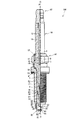
以下、本発明を具体化したスパークプラグの一実施の形態について、図面を参照して説明する。まず、図1,図2を参照し、一例としてのスパークプラグ100の全体の構造について説明する。図1は、スパークプラグ100の部分断面図である。図2は、スパークプラグ100の要部拡大断面図である。なお、本実施の形態のスパークプラグ100は、横飛火防止のため主体金具50と絶縁碍子10の軸線とをずらして組み付けている。以下、絶縁碍子10の軸線を一点鎖線Oで示し、主体金具50の軸線を一点鎖線Pで示す。また、軸線O方向を図面における上下方向とし、下側をスパークプラグ100の先端側、上側を後端側として説明する。
Hereinafter, an embodiment of a spark plug embodying the present invention will be described with reference to the drawings. First, the overall structure of the
図1に示すように、スパークプラグ100は、概略、絶縁碍子10と、この絶縁碍子10を保持する主体金具50と、絶縁碍子10内に軸線O方向に保持された中心電極20と、主体金具50の先端面57に基部32側の端面35を溶接され、先端部31の一側面が中心電極20の先端部22に対向する接地電極30と、絶縁碍子10の後端部に設けられた端子金具40とから構成されている。
As shown in FIG. 1, the
まず、このスパークプラグ100の絶縁碍子10について説明する。絶縁碍子10は、周知のようにアルミナ等を焼成して形成され、軸線O方向に軸孔12を有する筒状の絶縁部材である。軸線O方向の略中央には外径が最も大きい鍔部19が形成されており、これより後端側には後端側胴部18が形成されている。また、鍔部19より先端側には後端側胴部18より外径の小さい先端側胴部17と、その先端側胴部17よりも先端側で先端側胴部17よりもさらに外径の小さい脚長部13とが形成されている。脚長部13は先端側ほど縮径されており、スパークプラグ100が図示外の内燃機関に組み付けられた際には、その燃焼室に曝される。また、脚長部13と先端側胴部17との間は段部15として形成されている。
First, the
次に、中心電極20は、インコネル(商標名)600または601等のニッケル系合金等で形成され、内部に熱伝導性に優れる銅等からなる金属芯23を有している。中心電極20は絶縁碍子10の先端側の軸孔12内に保持されており、その先端部22は絶縁碍子10の先端面11から突出し、先端側に向かって径小となるように形成されている。図2に示すように、その先端部22の先端面には柱状の貴金属チップ90が、柱軸を中心電極20の軸線にあわせるようにして溶接されている。また、図1に示すように、中心電極20は、軸孔12の内部に設けられたシール体4およびセラミック抵抗3を経由して、後端側の端子金具40に電気的に接続されている。その端子金具40には高圧ケーブル(図示外)がプラグキャップ(図示外)を介して接続され、高電圧が印加されるようになっている。
Next, the
次いで、接地電極30について説明する。図2に示すように、接地電極30は耐腐食性の高い金属から構成され、一例として、インコネル(商標名)600または601等のニッケル系合金が用いられる。この接地電極30は自身の長手方向の横断面が略長方形を有しており、一端(基部32)側の端面35が主体金具50の先端面57に溶接により接合されている。また、接地電極30の他端(先端部31)は、内面33側が中心電極20の先端部22に対向するように屈曲されている。この先端部31の内面33には中心電極20の軸線にあわせて貴金属チップ91が接合されており、対向する貴金属チップ90との間で火花放電を行う火花放電ギャップが形成される。
Next, the
次に、主体金具50について説明する。図1に示すように主体金具50は、図示外の内燃機関のエンジンヘッドにスパークプラグ100を固定するための円筒状の金具であり、絶縁碍子10を取り囲むようにして保持している。このとき、絶縁碍子10の脚長部13の先端部分は主体金具50の先端面57よりも前方側(図1における下側)に突出されている。主体金具50は鉄系の材料より形成され、図示外のスパークプラグレンチが嵌合する工具係合部51と、図示外の内燃機関上部に設けられたエンジンヘッドに螺合するねじ部52とを備えている。
Next, the
また、主体金具50の工具係合部51と、絶縁碍子10の後端側胴部18との間には環状のリング部材6,7が介在されており、さらに両リング部材6,7の間にはタルク(滑石)9の粉末が充填されている。工具係合部51の後端側には加締め部53が形成されており、この加締め部53を加締めることにより、リング部材6,7およびタルク9を介して絶縁碍子10が主体金具50内で先端側に向け押圧される。これにより、主体金具50の内周に形成された段部56に、絶縁碍子10の先端側胴部17と脚長部13との間の段部15がパッキン80を介して支持されて、主体金具50と絶縁碍子10とが一体となる。主体金具50と絶縁碍子10との間の気密はパッキン80によって保持され、燃焼ガスの流出が防止される。また、主体金具50の中央部には鍔部54が形成されており、ねじ部52の後端部側(図1における上部)近傍、すなわち鍔部54の座面55にはガスケット5が嵌挿されている。
Further,
例えば主体金具のねじ部の呼び径がM12より大きいスパークプラグでは、絶縁碍子10の外周面14と主体金具50の内周面58との間の距離(クリアランス)が十分に大きく絶縁抵抗値が高いので、接地電極の周囲の電界強度の上昇にともなう横飛火が発生しにくい。そこで本実施の形態では、スパークプラグ100の大きさとしてねじ部52の呼び径がM12以下のものを対象としている。こうしたスパークプラグでは上記クリアランスの大きさが1.5mm以下となり、ねじ部の呼び径がM12より大きいスパークプラグと比べ、クリアランスにおける絶縁破壊が、より低い抵抗値で発生しやすい。スパークプラグ100において、絶縁碍子10の外周面14を、火花放電の際に周囲の電界強度が高くなる接地電極30から遠ざけて配置させることは、くすぶりが発生したときに、接地電極30側における絶縁碍子10の外周面14と主体金具50の内周面58との間で横飛火が発生することを防止する上で有効である。そこで、本実施の形態のスパークプラグ100では、その製造の一工程において、主体金具50の軸線Pと絶縁碍子10の軸線Oとをずらした状態で、両者の加締めを行った。
For example, in a spark plug in which the nominal diameter of the threaded portion of the metal shell is larger than M12, the distance (clearance) between the outer
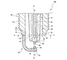
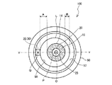
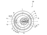
以下、図2〜図8を参照して、主体金具50と絶縁碍子10との相対的な配置位置の関係について説明する。図3は、図2の二点鎖線X−Xにおいてスパークプラグ100の先端部分を矢視方向から見た断面図である。図4は、主体金具50と絶縁碍子10とを軸ずれさせた状態で固定する方法について簡単に説明するための図である。図5は、主体金具50と接地電極30との間に生じた溶接ダレを完全に除去しない場合のスパークプラグ100の要部拡大断面図である。図6は、接地電極30の内側端点S1,S2と絶縁碍子10の軸線Oとの位置関係が好ましい場合について説明するためのスパークプラグ100の先端部分の断面図である。図7は、接地電極30の内側端点S1,S2と絶縁碍子10の軸線Oとの位置関係が好ましくない場合について説明するためのスパークプラグ100の先端部分の断面図である。図8は、接地電極30の内側端点S1,S2と絶縁碍子10の軸線Oとの位置関係が好ましくない場合について説明するためのスパークプラグ100の先端部分の断面図である。
Hereinafter, with reference to FIGS. 2-8, the relationship of the relative arrangement position of the
図2に示すように、主体金具50の軸線Pと接地電極30の中心とを含むスパークプラグ100の断面において、主体金具50の軸線Pの位置を基準として、絶縁碍子10の軸線Oは、接地電極30が接合された側とは反対側にずれて配置されている。より具体的には、以下に示す配置関係となる。まず、図3に示すように、主体金具50の先端面57上に接合される接地電極30の基部32側の端面35の中心をQとする。なお、本実施の形態では、接地電極30の横断面の形状すなわち端面35の形状が略長方形であるので、その対角線の交点を中心とする。ところで、前述したように主体金具50と接地電極30とは溶接されるため両者の接合部位には溶融部が形成されており、接地電極30の端面35の形状を明瞭に判断できない場合がある。この場合、接地電極30の断面形状が明瞭である部分を主体金具50の先端面57を含む平面(図2の一点鎖線X−Xにおいて矢視方向からみたスパークプラグ100の一部断面が含まれるX−X平面)上に投影し、その投影図を利用して上記した接地電極30の端面35の中心Qを決定すればよい。
As shown in FIG. 2, in the cross section of the
また、X−X平面において主体金具50に偏芯がなければ、主体金具50の先端面57の内周側の円(図3においてLで示す。)の中心点は、軸線PとX−X平面との交点となる。そこで、このX−X平面上で、中心Qと、軸線Pとを通る線をY−Yとする。そしてこのY−Y線上で、軸線Pよりも接地電極30側において、絶縁碍子10の外周面14と主体金具50の先端面57の内周側の円Lとの間の距離をAとし、また、軸線Pよりも接地電極30と反対側において、絶縁碍子10の外周面14と主体金具50の先端面57の内周側の円Lとの間の距離をBとする。このときA>Bが満たされるように、本実施の形態のスパークプラグ100では、主体金具50の内周面58と絶縁碍子10の外周面14との位置関係を規定している。
Further, if the
もっとも、通常、絶縁碍子10は、その絶縁性や耐熱性、耐久性の向上を図るという観点から、軸線Oに垂直な断面が真円形状となるように形成される。また、主体金具50についても同様に、通常は軸線Pに垂直な断面が真円形状となるように形成される。そこで、スパークプラグ100の製造過程では、上記Y−Y線上にて軸線Oの位置が軸線Pの位置に対し接地電極30とは反対側に位置するように主体金具50と絶縁碍子10との位置決めを行い、両者を仮固定した状態で加締め部53の加締めを行うとよい。このように、主体金具50の軸線Pと絶縁碍子10の軸線Oを基準に位置決めを行えば、上記したA>Bを満たすことができる。
However, normally, the
ところで、加締めの際に、主体金具50と絶縁碍子10との位置決めを行う具体的な方法としては、図4に示す、位置決め部材500を用いる方法を一例として挙げることができる。この位置決め部材500は貫通孔520を有する円筒状をなし、外周面501が主体金具50の内周面58に係合し、貫通孔520の内周面502が絶縁碍子10の外周面14に係合する部材である。外周面501がなす円筒形状の軸と、内周面502がなす円筒形状の軸との位置関係が、加締め後の主体金具50の軸線Pと絶縁碍子10の軸線Oとの位置関係となるように構成されている。すなわち、位置決め部材500の縦断面において、外周面501と内周面502との差(厚み)が図3で説明したA>Bを満たす部位を有するように、外周面501がなす円筒形状の軸と内周面502がなす円筒形状の軸とが偏芯されている。また、主体金具50に対する自身の位置決めが行えるように、位置決め部材500には、主体金具50への挿入方向の後端側に主体金具50の先端面57に当接させる段状の台座部510が設けられている。この台座部510は一部が軸方向に切り欠かれた切欠部530を有し、その切欠部530に主体金具50に接合された接地電極30が係合することで、加締め後の主体金具50の軸線Pと絶縁碍子10の軸線Oとの軸ずれ方向に、上記した外周面501がなす円筒形状の軸と内周面502がなす円筒形状の軸との偏芯方向が揃えられるように構成されている。
By the way, as a specific method for positioning the
このような位置決め部材500を主体金具50の先端側から挿入し、接地電極30を台座部510の切欠部530に係合させつつ、外周面501を、主体金具50の内周面58に係合させる。この状態で主体金具50の後端側からパッキン80と絶縁碍子10を挿入し、絶縁碍子10の先端側の外周面14を位置決め部材500の貫通孔520の内周面502に係合させる。そして、リング部材6,7とタルク9を配置させた後に主体金具50の加締め部53を加締め、主体金具50と絶縁碍子10とを一体に固定すれば、主体金具50の軸線Pと絶縁碍子10の軸線Oとが軸ずれし、上記したA>Bが満たされたスパークプラグ100を容易に作製することができる。
Such a
なお、上記のように軸ずれした状態で絶縁碍子10を主体金具50に固定すると、絶縁碍子10には軸線Oに対し偏った内部応力が生ずる虞があるが、本実施の形態では絶縁碍子10を主体金具50内にてパッキン80、タルク9およびリング部材6,7によって支持する構成であるため、これら部材によって内部応力が吸収される。このように固定される主体金具50と絶縁碍子10との位置関係は、後述する評価試験の結果に基づくと、距離Aと距離Bとの差を0.1mm以上0.3mm以下とすることが望ましい。
If the
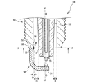
ところで、接地電極30は主体金具50の先端面57に抵抗溶接により接合されるが、その際に溶接ダレが生ずる。通常、抵抗溶接後の工程にてこの溶接ダレの切削を行うが、図5に示すように、この溶接ダレを完全に(主体金具50の内周面58に対して平滑となるように)除去しない場合であれば、上記X−X平面において主体金具50の先端面57の内周側の円Lより、その円Lの中心点(すなわち軸線Pの位置)に向かって突出する寸法(図中Gで示す。)を0.1mm以下とした溶接突起部85として残してもよい。溶接突起部85の突出寸法Gが0.1mm以下であれば、本実施の形態のように、主体金具50の軸線Pと絶縁碍子10の軸線Oとをずらして配置するために必要なクリアランスを確保することができる。溶接突起部85の突出寸法Gが0.1mmより大きいと、くすぶりが発生したときに溶接突起部85の突出した先端部分と絶縁碍子10の外周面14との間で火花放電が行われてしまう虞がある。なお、本実施の形態で説明したY−Y線上において、溶接突起部85の突出した先端と絶縁碍子10の外周との間の距離をDとすると、距離Dは距離Bよりも大きく、より具体的には上記同様、距離Dと距離Bとの差を0.1mm以上0.3mm以下とすることが望ましい。
By the way, the
また、前述したように接地電極30はその横断面が略長方形であるため、隣り合う側面同士が稜線部を構成する。一般に先尖部分ではその周囲の電界強度が高まりやすい。そこで、本実施の形態では、接地電極30の4つの側面のうち軸線P側に配置された面(すなわち内面33)の長手側の両側縁にて構成される稜線部で生ずる電界集中による横飛火への影響を低減するため、以下のような主体金具50と絶縁碍子10との位置関係を規定している。
Moreover, since the
まず、図6に示すように、主体金具50の先端面57を含む平面(上記したX−X平面)において、接地電極30の基部32の端面35の輪郭線を構成する4つの線分のうち、主体金具50の軸線Pの位置に近い側(内側)に配置される内側線分の両端の2点をそれぞれ内側端点S1,S2とする。この内側端点S1,S2は、接地電極30の内面33と2つの側面とがなす2つの稜線部をそれぞれX−X平面に投影した点に相当し、電界集中が生じやすい箇所にあたる。次に、この2つの内側端点S1,S2と、主体金具50の先端面57の内周側の円Lの中心点(X−X平面上の軸線Pの位置)とを通る2つの直線をそれぞれT1,T2とする。すると、主体金具50の先端面57の内周側の円L内の領域は、直線T1,T2により4つの扇状の領域に分割される。そこで、軸線Pの位置に対し接地電極30の位置する側とは反対側において、直線T1,T2と先端面57の内周側の円Lの一部とで囲まれて形成される鋭角扇状の領域をUとし、図6において斜線で示した。本実施の形態では、X−X平面上において、この鋭角扇状の領域L内に絶縁碍子10の軸線Oの位置(軸線OとX−X平面との交点)が配置されるように、主体金具50と絶縁碍子10との位置関係を規定している。
First, as shown in FIG. 6, among the four line segments constituting the contour line of the
ここで、主体金具50の軸線Pの位置を通りY−Y線と直交する直線で主体金具50の先端面57の内周側の円Lを2分する領域のうち、接地電極30から遠い側の領域内において、絶縁碍子10の軸線Oの位置が内側端点S1,S2に近い側では、内側端点S1,S2に生ずる電界集中の影響が比較的大きい。このため、例えば図7に示すように、Y−Y線と直交する方向においては、軸線Oの位置と内側端点S1との間の距離と、軸線Oの位置と内側端点S2との間の距離との差は、軸線Oの位置を内側端点S1もしくは内側端点S2の一方に近づけるほど大きくなる。従って、Y−Y線と直交する方向において、軸線Oの位置を内側端点S1および内側端点S2の双方から均等な位置に配置させるほど、一方の内側端点から受ける電界集中の影響を小さくすることができる。
Here, in the region that divides the circle L on the inner peripheral side of the
一方、主体金具50の軸線Pの位置を通りY−Y線と直交する直線で主体金具50の先端面57の内周側の円Lを2分する領域のうち、接地電極30から遠い側の領域内において、軸線Oの位置が内側端点S1,S2から遠い側では、内側端点S1,S2に生ずる電界集中の影響が比較的小さい。このため、Y−Y線と直交する方向においては、軸線Oの位置が内側端点S1もしくは内側端点S2の一方に近づいても、軸線Oの位置と内側端点S1との間の距離と、軸線Oの位置と内側端点S2との間の距離との差は大きく変わらない。また、例えば図8に示すように、Y−Y線と直交する方向において、軸線Oの位置が内側端点S1と内側端点S2との間の位置より外側にずれて配置された場合、そのずれた側において、主体金具50の内周面58と絶縁碍子10の外周面14との間の距離が小さくなり好ましくない。
On the other hand, in a region that bisects the circle L on the inner peripheral side of the
これらのことより、図6に示したように、主体金具50の軸線Pの位置を通りY−Y線と直交する直線で主体金具50の先端面57の内周側の円Lを2分する領域のうち、接地電極30から遠い側の領域内において、絶縁碍子10の軸線Oの位置が内側端点S1,S2に近い側では、Y−Y線と直交する方向において軸線Oの位置を内側端点S1および内側端点S2の双方から略均等な位置に配置させる。また、主体金具50の軸線Pの位置を通りY−Y線と直交する直線で主体金具50の先端面57の内周側の円Lを2分する領域のうち、接地電極30から遠い側の領域内において、絶縁碍子10の軸線Oの位置が内側端点S1,S2に遠い側では、Y−Y線と直交する方向において、内側端点S1と内側端点S2との間の範囲内でずらして配置することができるようにする。すなわち、上記の鋭角扇状の領域U内に絶縁碍子10の軸線Oの位置が配置されるように規定すれば、スパークプラグ100の製造の際における主体金具50の軸線Pと絶縁碍子の軸線Oとの位置決めの公差を大きくしても、内側端点S1,S2に生ずる電界集中の影響を受けにくく、横飛火を抑制することができる。
Accordingly, as shown in FIG. 6, the circle L on the inner peripheral side of the
なお、本実施の形態のスパークプラグ100では、接地電極30の先端部31の内面33に貴金属チップ91が接合される。スパークプラグ100の完成後において、屈曲された接地電極30の貴金属チップ91と、中心電極20の先端部22に接合された貴金属チップ90とは、図2に示すように、互いに向かい合う位置関係であることが望ましい。そのためには、貴金属チップ91を接地電極30に接合する際に、主体金具50の軸線Pと絶縁碍子10の軸線Oとのずれ量にあわせて、接地電極30の内面33上の貴金属チップ91の接合位置を調整するとよい。具体的には、従来のスパークプラグにおける接地電極上の貴金属チップの接合位置(接地電極を屈曲したときに貴金属チップの軸線が主体金具の軸線Pと一致する接合位置)を基準とし、接地電極30の先端側に向けて、軸線Oと軸線Pとのずれ量(すなわち図3において(A−B)/2で求められる大きさに相当する。)の分だけずらした位置に貴金属チップ91を接合するとよい。
In the
このように構成したスパークプラグについて本発明の効果を確認するため、以下に示す評価試験を行った。 In order to confirm the effect of this invention about the spark plug comprised in this way, the evaluation test shown below was done.
[実施例1]
この評価試験では、主体金具の軸線Pに対する絶縁碍子の軸線Oのずれの大きさ(軸ずれ量)を−0.3mm〜+0.4mmの範囲で0.1mmずつ異ならせて作製したスパークプラグの8つのサンプルを用い、それぞれについて横飛火の発生率を確認した。なお軸ずれ量は、図3で説明したスパークプラグ100の断面において、Y−Y線上における軸線Pの位置と軸線Oの位置との間の距離とした。このとき、主体金具50の軸線Pの位置を基準とする絶縁碍子10の軸線Oの位置が、接地電極30の接合された側である場合を負、それとは反対側である場合を正とした。
[Example 1]
In this evaluation test, a spark plug produced by varying the magnitude of the deviation (axis deviation) of the insulator axis O from the axis P of the metal shell by 0.1 mm in the range of -0.3 mm to +0.4 mm. Eight samples were used, and the occurrence rate of side fire was confirmed for each. Note that the amount of axial misalignment is the distance between the position of the axis P and the position of the axis O on the YY line in the cross section of the
スパークプラグの規格としては主体金具のねじ部の呼び径がM10のもの(絶縁碍子の外周面と主体金具の内周面との間のクリアランスが、両者の軸線O,Pを一致させたときに1.5mmであるもの)を用いた。そして各サンプルの絶縁碍子の先端部分にカーボンを付着させてくすぶり状態とした。これらサンプルをチャンバー内に配置し、0.6MPaの気圧下で100回の火花放電を行い、その間の横飛火の発生回数を測定して横飛火発生率を求めた。なお、各サンプルの火花放電ギャップの大きさは0.9mmとした。 As for the standard of the spark plug, the nominal diameter of the thread portion of the metal shell is M10 (when the clearance between the outer peripheral surface of the insulator and the inner peripheral surface of the metal shell matches the axes O and P of the both) 1.5 mm). Carbon was attached to the tip portion of the insulator of each sample to form a smoldering state. These samples were placed in a chamber, spark discharge was performed 100 times at a pressure of 0.6 MPa, and the number of occurrences of side fire during that time was measured to obtain the side fire occurrence rate. In addition, the magnitude | size of the spark discharge gap of each sample was 0.9 mm.
図9に示すように、軸ずれ量が0mm、すなわち主体金具の軸線と絶縁碍子の軸線とを一致させたスパークプラグの場合、横飛火の発生率は30〜40%であった。軸ずれ量が負の方向に大きくなる、すなわち絶縁碍子の軸線のずれが接地電極側へ大きくなるに伴って距離A(図3参照)が小さくなるため横飛火の発生率は高くなり、軸ずれ量が−0.3mmでは横飛火の発生率が100%となった。一方で、軸ずれ量が正の方向に大きくなる、すなわち絶縁碍子の軸線のずれが接地電極と反対側へ大きくなると、距離Aが大きくなるため横飛火の発生率は小さくなる。しかし、その軸ずれ量がさらに大きくなると距離B(図3参照)が小さくなるため、X−X平面(図2参照)において接地電極とは反対側にて横飛火が発生し、横飛火の発生率が高くなることがわかった。具体的には、軸ずれ量が正の方向に0.1mm以上0.3mm以下である場合、横飛火の発生率は製品として許容できる20%以下であることが確認できた。 As shown in FIG. 9, in the case of the spark plug in which the amount of axial deviation was 0 mm, that is, the spark plug in which the axis of the metal shell and the axis of the insulator coincided with each other, the occurrence rate of side fire was 30 to 40%. As the amount of axial deviation increases in the negative direction, that is, the distance A (see FIG. 3) decreases as the axial deviation of the insulator increases toward the ground electrode side, the incidence of side fire increases and the axial deviation occurs. When the amount was -0.3 mm, the occurrence rate of side fire was 100%. On the other hand, when the amount of axial deviation increases in the positive direction, that is, when the axial deviation of the insulator increases toward the side opposite to the ground electrode, the distance A increases and the occurrence rate of side fire decreases. However, since the distance B (refer to FIG. 3) decreases as the amount of the axial deviation further increases, a horizontal spark occurs on the side opposite to the ground electrode in the XX plane (refer to FIG. 2), and a horizontal spark occurs. It turns out that the rate is high. Specifically, when the amount of axial misalignment is 0.1 mm or more and 0.3 mm or less in the positive direction, it was confirmed that the occurrence rate of side fire was 20% or less acceptable as a product.
なお、上記評価試験では、さらに比較例として、呼び径がM10である上記クリアランスを1.4mmとしたものと、呼び径がM12である上記クリアランスを1.6mmとしたものとを用意して、同様の試験を行った。すると、いずれの場合でも、軸ずれ量が正の方向に0.1mm以上0.3mm以下の範囲においては、横飛火の発生率が製品として許容できる20%以下であることが確認できた。 In the evaluation test, as a comparative example, the clearance having a nominal diameter of M10 was set to 1.4 mm, and the clearance having a nominal diameter of M12 was set to 1.6 mm, A similar test was conducted. Then, in any case, it was confirmed that the occurrence rate of side fire was 20% or less acceptable as a product when the amount of axial deviation was in the range of 0.1 mm to 0.3 mm in the positive direction.
火花放電の際には接地電極の周囲の電界強度が高まることにより、接地電極側の主体金具の内周面と絶縁碍子の外周面との間の絶縁破壊電圧が低くなる。しかし、実施例1に示すように、主体金具の軸線に対し絶縁碍子の軸線を接地電極と反対側にずらすことによって、主体金具の内周面と絶縁碍子の外周面との間の絶縁破壊電圧を全周に渡って一様とすることができ、横飛火を防止することができることが確認できた。 During the spark discharge, the electric field strength around the ground electrode is increased, so that the dielectric breakdown voltage between the inner peripheral surface of the metal shell on the ground electrode side and the outer peripheral surface of the insulator is lowered. However, as shown in Example 1, the dielectric breakdown voltage between the inner peripheral surface of the metal shell and the outer peripheral surface of the insulator is obtained by shifting the axis of the insulator to the opposite side of the ground electrode with respect to the axis of the metal shell. Can be made uniform over the entire circumference, and it has been confirmed that side fire can be prevented.
なお、本発明は各種の変形が可能なことはいうまでもない。例えば、本実施の形態では主体金具50の軸線Pと絶縁碍子の軸線Oとが平行を維持した状態で両者の位置関係をずらしたが、軸線Pに対し軸線Oを傾けることによってずらしてもよい。図10に示すスパークプラグ200のように、主体金具50の軸線Pと、絶縁碍子10の軸線Oとが非平行となるように主体金具50と絶縁碍子10とを仮固定した状態で加締め部53を加締め、両者を一体化する。このとき、主体金具50の先端面57を含むX−X平面において、本実施の形態と同様に、軸線Pよりも接地電極30側における絶縁碍子10の外周面14と主体金具50の先端面57の内周側の円Lとの間の距離Aが、軸線Pよりも接地電極30と反対側における絶縁碍子10の外周面14と主体金具50の先端面57の内周側の円Lとの間の距離Bよりも大きくなるように、主体金具50と絶縁碍子10とを仮固定すればよい。
Needless to say, the present invention can be modified in various ways. For example, in the present embodiment, the positional relationship between the axis line P of the
また、図11に示すスパークプラグ300のように、絶縁碍子310の先端面311が、主体金具50の先端面57よりも後端側に位置してもよい。この場合、絶縁碍子310の先端部の外周面314に沿って延長した面と、絶縁碍子310の先端面311を含む平面との交点Fから形成される仮想円を想定する。そして、その仮想円を、主体金具50の先端面57を含むX−X平面に投影した仮想円と、主体金具50の先端面57の内周側の円との間の距離に基づき、本実施の形態における距離Aおよび距離Bを求め、距離Aが距離Bより大きくなるように主体金具50に対し絶縁碍子310を固定するとよい。
In addition, like the
また、図2に示す、主体金具50の先端面57と内周面58とがなす稜線部59に面取り加工を行ってもよい。例えば、図12に示すスパークプラグ400では、主体金具450の先端面457と内周面458との間に面取り部459を形成した。前述したように先尖部分ではその周囲の電界強度が高まり火花放電が生じやすいため、先端面457と内周面458とがなす稜線部に面取り加工を施し先尖部分をなくせば横飛火の発生を低減することができる。また、主体金具450と接地電極30との抵抗溶接の際に溶接ダレが面取り部459に生じても、その溶接ダレの形成位置が主体金具450の内周面458よりも外方側となるため、内周面458よりも内方側に突出させないようにすることができる。
Moreover, you may chamfer to the
上記図12に示したスパークプラグ400は面取り部459にC面取りを施した例であるが、図13に示すスパークプラグ410の面取部469のように、主体金具460の先端面467と内周面468との間にR面取りを施しても同様の効果が得られるし、あるいはテーパ面取り(図示外)を施しても同様に効果を得ることができる。なお、主体金具50の先端面57と内周面58とがなす稜線部59(図2参照)に発生する電界集中を防止する上で、図12に示した面取り部459のようにC面取りを施した場合であればC0.1以上、また、図13に示した面取部469のようにR面取りを施した場合であればR0.1以上とすると好適である。
The
なお、面取り加工を行った際には、特に、接地電極30の中心電極20側の面と、主体金具450,460の内周面458,468とを軸線O方向において揃える必要はない。すなわち、接地電極30の基部32の端面と接地電極30の中心電極20側の面とがなす稜線部は、図12や図13のように面取り部459,469にかかってもよい。また、その稜線部が上記面取り部459,469にかからないようにし、面取り後の先端面457,467内にそれぞれ収まるように配置すれば、この稜線部における電界の集中を抑制することも可能である。
When chamfering is performed, it is not particularly necessary to align the surface of the
また、絶縁碍子10の軸線O断面が真円でなくともよい。例えば図14に示すスパークプラグ500のように、絶縁碍子510の先端部分において、接地電極30側に配置される部分の肉厚を薄く構成した薄肉部519を形成してもよい。このような構成の絶縁碍子510を使用すれば、組み付けの際に絶縁碍子510の軸線Oと主体金具50の軸線Pとを一致させることができる。そして主体金具50の先端面57を含むX−X平面において、接地電極30の中心Qと主体金具50の軸線Oとを通るY−Y線上で、主体金具50の先端面57の内周側の円Lと、絶縁碍子10の薄肉部519との間の距離をEとすると、距離Eが本実施の形態の距離Bよりも大きくなるように構成すればよい。しかしこのような絶縁碍子510では、肉厚の薄い部分等が生じ耐久性や絶縁性が低下する虞があるため、本実施の形態のように、主体金具の軸位置と絶縁碍子の軸位置とをずらすことが好ましい。
Moreover, the axis O section of the
本発明は内燃機関用のスパークプラグに適用することができる。 The present invention can be applied to a spark plug for an internal combustion engine.
10 絶縁碍子
12 軸孔
14 外周面
20 中心電極
30 接地電極
31 先端部
32 基部
50 主体金具
52 ねじ部
57 先端面
59 稜角部
85 溶接突起部
100 スパークプラグ
459 C面取り部
469 R面取り部
DESCRIPTION OF
Claims (5)
前記主体金具先端面の内周側の円の中心点と、前記接地電極の前記一端側の端面の中心とを結ぶ直線上の距離において、
前記接地電極の位置する側における、前記主体金具先端面を含む平面上での前記絶縁碍子の断面の外周面もしくはその平面に投影した前記絶縁碍子の外周面と、前記主体金具先端面の内周側の円との間の距離をAとし、
前記接地電極の位置する側と反対側における、前記主体金具先端面を含む平面上での前記絶縁碍子の断面の外周面もしくはその平面に投影した前記絶縁碍子の外周面と、前記主体金具先端面の内周側の円との間の距離をBとしたとき、
A>Bとなるように、前記主体金具の軸線と、前記絶縁碍子の軸線とをずらして配置し、さらに、
前記主体金具は、その外側面に、呼び径がM12以下のねじ部を備え、
0.1mm≦A−B≦0.3mmとなるように、前記主体金具の軸線と、前記絶縁碍子の軸線とをずらして配置したことを特徴とするスパークプラグ。 A central electrode, an axial hole extending in the axial direction of the central electrode, an insulator holding the central electrode inside the axial hole, and surrounding the insulator in the radial direction to hold the insulator A spark plug comprising a cylindrical metal shell, and a ground electrode made of a metal wire bent so that an end surface on one end side is joined to a front end surface of the metal shell and the other end faces the center electrode. And
At a distance on a straight line connecting the center point of the circle on the inner peripheral side of the front end surface of the metal shell and the center of the end surface on the one end side of the ground electrode,
The outer peripheral surface of the cross section of the insulator on the plane including the front end surface of the metal shell on the side where the ground electrode is located, or the outer peripheral surface of the insulator projected onto the plane, and the inner periphery of the front surface of the main metal shell Let A be the distance to the side circle,
The outer peripheral surface of the cross-section of the insulator on the plane including the front end surface of the metal shell on the side opposite to the side where the ground electrode is located, or the outer peripheral surface of the insulator projected on the plane, and the front surface of the main metal shell When the distance between the inner circle and the circle is B,
A> B so that the axis of the metal shell is shifted from the axis of the insulator, so that A> B ,
The metal shell is provided with a threaded portion having a nominal diameter of M12 or less on the outer surface thereof,
A spark plug , wherein the axis of the metallic shell and the axis of the insulator are shifted so that 0.1 mm ≦ A−B ≦ 0.3 mm .
前記主体金具先端面の内周側の円の中心点と、前記接地電極の前記一端側の端面の中心とを結ぶ直線上の距離において、
前記接地電極の位置する側における、前記主体金具先端面を含む平面上での前記絶縁碍子の断面の外周面もしくはその平面に投影した前記絶縁碍子の外周面と、前記主体金具先端面の内周側の円との間の距離をAとし、
前記接地電極の位置する側と反対側における、前記主体金具先端面を含む平面上での前記絶縁碍子の断面の外周面もしくはその平面に投影した前記絶縁碍子の外周面と、前記主体金具先端面の内周側の円との間の距離をBとしたとき、
A>Bとなるように、前記主体金具の軸線と、前記絶縁碍子の軸線とをずらして配置し、さらに、
前記主体金具先端面を含む平面上での前記絶縁碍子の断面の外周面もしくはその平面に投影した前記絶縁碍子の外周面と、前記主体金具先端面の内周側の円との間の距離が1.5mm以下であるスパークプラグにおいて、
0.1mm≦A−B≦0.3mmとなるように、前記主体金具の軸線と、前記絶縁碍子の軸線とをずらして配置したことを特徴とするスパークプラグ。 A central electrode, an axial hole extending in the axial direction of the central electrode, an insulator holding the central electrode inside the axial hole, and surrounding the insulator in the radial direction to hold the insulator A spark plug comprising a cylindrical metal shell, and a ground electrode made of a metal wire bent so that an end surface on one end side is joined to a front end surface of the metal shell and the other end faces the center electrode. And
At a distance on a straight line connecting the center point of the circle on the inner peripheral side of the front end surface of the metal shell and the center of the end surface on the one end side of the ground electrode,
The outer peripheral surface of the cross section of the insulator on the plane including the front end surface of the metal shell on the side where the ground electrode is located, or the outer peripheral surface of the insulator projected onto the plane, and the inner periphery of the front surface of the main metal shell Let A be the distance to the side circle,
The outer peripheral surface of the cross-section of the insulator on the plane including the front end surface of the metal shell on the side opposite to the side where the ground electrode is located, or the outer peripheral surface of the insulator projected on the plane, and the front surface of the main metal shell When the distance between the inner circle and the circle is B,
A> B so that the axis of the metal shell is shifted from the axis of the insulator, so that A> B,
The distance between the outer peripheral surface of the cross section of the insulator on the plane including the front end surface of the metal shell or the outer peripheral surface of the insulator projected onto the plane and the circle on the inner peripheral side of the front surface of the main metal shell is In the spark plug which is 1.5 mm or less,
A spark plug , wherein the axis of the metallic shell and the axis of the insulator are shifted so that 0.1 mm ≦ A−B ≦ 0.3 mm .
前記主体金具先端面の内周側の円の一部と
によって形成される鋭角扇状の領域のうち、前記接地電極の位置する側とは反対側における前記鋭角扇状の領域内に、前記絶縁碍子の軸線と前記主体金具先端面を含む平面との交点が位置することを特徴とする請求項1乃至4のいずれかに記載のスパークプラグ。 Two straight lines respectively passing through two inner end points of the ground electrode on a plane including the front end surface of the metallic shell and a center point of a circle on the inner peripheral side of the front end surface of the metallic shell on the plane;
In the acute fan-shaped region formed on the inner peripheral side of the front end surface of the metal shell and in the acute fan-shaped region on the side opposite to the side where the ground electrode is located, The spark plug according to any one of claims 1 to 4 , wherein an intersection of an axis and a plane including the front end surface of the metal shell is located.
Priority Applications (1)
| Application Number | Priority Date | Filing Date | Title |
|---|---|---|---|
| JP2006037386A JP4680792B2 (en) | 2005-03-08 | 2006-02-15 | Spark plug |
Applications Claiming Priority (2)
| Application Number | Priority Date | Filing Date | Title |
|---|---|---|---|
| JP2005063747 | 2005-03-08 | ||
| JP2006037386A JP4680792B2 (en) | 2005-03-08 | 2006-02-15 | Spark plug |
Publications (2)
| Publication Number | Publication Date |
|---|---|
| JP2006286612A JP2006286612A (en) | 2006-10-19 |
| JP4680792B2 true JP4680792B2 (en) | 2011-05-11 |
Family
ID=37408265
Family Applications (1)
| Application Number | Title | Priority Date | Filing Date |
|---|---|---|---|
| JP2006037386A Active JP4680792B2 (en) | 2005-03-08 | 2006-02-15 | Spark plug |
Country Status (1)
| Country | Link |
|---|---|
| JP (1) | JP4680792B2 (en) |
Families Citing this family (11)
| Publication number | Priority date | Publication date | Assignee | Title |
|---|---|---|---|---|
| CN101689753B (en) * | 2007-08-08 | 2012-05-23 | 日本特殊陶业株式会社 | Spark plug and its manufacturing method |
| JP4965492B2 (en) * | 2008-03-28 | 2012-07-04 | 日本特殊陶業株式会社 | Internal combustion engine |
| JP4875016B2 (en) * | 2008-03-28 | 2012-02-15 | 日本特殊陶業株式会社 | Internal combustion engine |
| JP4750215B2 (en) * | 2009-07-06 | 2011-08-17 | 日本特殊陶業株式会社 | Spark plug |
| JP5878880B2 (en) * | 2013-02-13 | 2016-03-08 | 日本特殊陶業株式会社 | Spark plug and manufacturing method thereof |
| JP6566890B2 (en) * | 2016-02-23 | 2019-08-28 | 日本特殊陶業株式会社 | Spark plug and ignition device |
| JP6767938B2 (en) * | 2017-07-03 | 2020-10-14 | 日本特殊陶業株式会社 | Spark plug |
| JP6661245B2 (en) * | 2017-08-18 | 2020-03-11 | 日本特殊陶業株式会社 | Spark plug |
| JP6559193B2 (en) * | 2017-08-18 | 2019-08-14 | 日本特殊陶業株式会社 | Spark plug |
| JP6611769B2 (en) | 2017-09-02 | 2019-11-27 | 日本特殊陶業株式会社 | Spark plug |
| JP7468217B2 (en) | 2020-07-22 | 2024-04-16 | 株式会社デンソー | Spark plug |
Citations (2)
| Publication number | Priority date | Publication date | Assignee | Title |
|---|---|---|---|---|
| JP2003068420A (en) * | 2001-08-23 | 2003-03-07 | Ngk Spark Plug Co Ltd | Spark plug for internal combustion engine |
| JP2005339981A (en) * | 2004-05-27 | 2005-12-08 | Nissan Motor Co Ltd | Spark plug |
Family Cites Families (3)
| Publication number | Priority date | Publication date | Assignee | Title |
|---|---|---|---|---|
| JPS60140391U (en) * | 1984-02-27 | 1985-09-17 | トヨタ自動車株式会社 | spark plug |
| JPS612287A (en) * | 1984-06-15 | 1986-01-08 | 日本特殊陶業株式会社 | Small-sized ignition plug for vehicle |
| JPH09256939A (en) * | 1996-03-22 | 1997-09-30 | Mitsubishi Motors Corp | Spark plug and its mounting structure |
-
2006
- 2006-02-15 JP JP2006037386A patent/JP4680792B2/en active Active
Patent Citations (2)
| Publication number | Priority date | Publication date | Assignee | Title |
|---|---|---|---|---|
| JP2003068420A (en) * | 2001-08-23 | 2003-03-07 | Ngk Spark Plug Co Ltd | Spark plug for internal combustion engine |
| JP2005339981A (en) * | 2004-05-27 | 2005-12-08 | Nissan Motor Co Ltd | Spark plug |
Also Published As
| Publication number | Publication date |
|---|---|
| JP2006286612A (en) | 2006-10-19 |
Similar Documents
| Publication | Publication Date | Title |
|---|---|---|
| JP4680792B2 (en) | Spark plug | |
| US7557496B2 (en) | Spark plug which can prevent lateral sparking | |
| KR101395376B1 (en) | Spark plug and its manufacturing method | |
| JP4787339B2 (en) | Plasma jet ignition plug | |
| US8657641B2 (en) | Method for forming an electrode for a spark plug | |
| US9843166B2 (en) | Spark plug and method for manufacturing spark plug | |
| EP2333916B1 (en) | Sparkplug and manufacturing method therefor | |
| US20060220511A1 (en) | Spark plug having ground electrode protruding member with inner and outer edges | |
| JP2011175980A5 (en) | ||
| US20110241522A1 (en) | Spark ignition device for an internal combustion engine, metal shell therefor and methods of construction thereof | |
| WO2021111719A1 (en) | Spark plug | |
| JP5923011B2 (en) | Spark plug | |
| US8896194B2 (en) | Spark ignition device and ground electrode therefor and methods of construction thereof | |
| EP2538506B1 (en) | Spark plug | |
| JP2005203110A (en) | Manufacturing method of spark plug, and spark plug | |
| CN112740493B (en) | Spark plug | |
| EP2226912B1 (en) | Spark plug | |
| JP4013891B2 (en) | Spark plug | |
| JP2009163923A (en) | Spark plug | |
| JP6411433B2 (en) | Spark plug | |
| US9041275B2 (en) | Spark plug for internal combustion engine and method of manufacturing the same | |
| US10320158B2 (en) | Spark plug | |
| JP2006286327A (en) | Spark plug | |
| JP2023108915A (en) | Spark plug for internal combustion engine | |
| WO2019069640A1 (en) | Ignition plug |
Legal Events
| Date | Code | Title | Description |
|---|---|---|---|
| RD04 | Notification of resignation of power of attorney |
Free format text: JAPANESE INTERMEDIATE CODE: A7424 Effective date: 20080223 |
|
| A621 | Written request for application examination |
Free format text: JAPANESE INTERMEDIATE CODE: A621 Effective date: 20080421 |
|
| A977 | Report on retrieval |
Free format text: JAPANESE INTERMEDIATE CODE: A971007 Effective date: 20101005 |
|
| A131 | Notification of reasons for refusal |
Free format text: JAPANESE INTERMEDIATE CODE: A131 Effective date: 20101019 |
|
| A521 | Request for written amendment filed |
Free format text: JAPANESE INTERMEDIATE CODE: A523 Effective date: 20101215 |
|
| TRDD | Decision of grant or rejection written | ||
| A01 | Written decision to grant a patent or to grant a registration (utility model) |
Free format text: JAPANESE INTERMEDIATE CODE: A01 Effective date: 20110111 |
|
| A01 | Written decision to grant a patent or to grant a registration (utility model) |
Free format text: JAPANESE INTERMEDIATE CODE: A01 |
|
| A61 | First payment of annual fees (during grant procedure) |
Free format text: JAPANESE INTERMEDIATE CODE: A61 Effective date: 20110203 |
|
| R150 | Certificate of patent or registration of utility model |
Ref document number: 4680792 Country of ref document: JP Free format text: JAPANESE INTERMEDIATE CODE: R150 Free format text: JAPANESE INTERMEDIATE CODE: R150 |
|
| FPAY | Renewal fee payment (event date is renewal date of database) |
Free format text: PAYMENT UNTIL: 20140210 Year of fee payment: 3 |
|
| FPAY | Renewal fee payment (event date is renewal date of database) |
Free format text: PAYMENT UNTIL: 20140210 Year of fee payment: 3 |
|
| R250 | Receipt of annual fees |
Free format text: JAPANESE INTERMEDIATE CODE: R250 |
|
| R250 | Receipt of annual fees |
Free format text: JAPANESE INTERMEDIATE CODE: R250 |
|
| R250 | Receipt of annual fees |
Free format text: JAPANESE INTERMEDIATE CODE: R250 |
|
| R250 | Receipt of annual fees |
Free format text: JAPANESE INTERMEDIATE CODE: R250 |
|
| R250 | Receipt of annual fees |
Free format text: JAPANESE INTERMEDIATE CODE: R250 |
|
| R250 | Receipt of annual fees |
Free format text: JAPANESE INTERMEDIATE CODE: R250 |
|
| R250 | Receipt of annual fees |
Free format text: JAPANESE INTERMEDIATE CODE: R250 |
|
| R250 | Receipt of annual fees |
Free format text: JAPANESE INTERMEDIATE CODE: R250 |
|
| R250 | Receipt of annual fees |
Free format text: JAPANESE INTERMEDIATE CODE: R250 |
|
| S531 | Written request for registration of change of domicile |
Free format text: JAPANESE INTERMEDIATE CODE: R313531 |
|
| R350 | Written notification of registration of transfer |
Free format text: JAPANESE INTERMEDIATE CODE: R350 |
|
| R250 | Receipt of annual fees |
Free format text: JAPANESE INTERMEDIATE CODE: R250 |
|
| R250 | Receipt of annual fees |
Free format text: JAPANESE INTERMEDIATE CODE: R250 |