JP4679645B2 - Water server - Google Patents
Water server Download PDFInfo
- Publication number
- JP4679645B2 JP4679645B2 JP2009008718A JP2009008718A JP4679645B2 JP 4679645 B2 JP4679645 B2 JP 4679645B2 JP 2009008718 A JP2009008718 A JP 2009008718A JP 2009008718 A JP2009008718 A JP 2009008718A JP 4679645 B2 JP4679645 B2 JP 4679645B2
- Authority
- JP
- Japan
- Prior art keywords
- water
- bag
- cooling
- box
- outer case
- Prior art date
- Legal status (The legal status is an assumption and is not a legal conclusion. Google has not performed a legal analysis and makes no representation as to the accuracy of the status listed.)
- Expired - Fee Related
Links
Images


Description
本発明はバッグインボックスを使用するウォーターサーバーに係り、特に冷水用のウォーターサーバーにおいて、雑菌の侵入及び繁殖を阻止できると共に冷却効果を低下させることなくバッグインボックスの装填や空容器の取り出し作業を容易になし得るようにしたウォーターサーバーに関するものである。 The present invention relates to a water server using a bag-in-box, and in particular, in a cold-water water server, it is possible to prevent the invasion and propagation of germs and to load a bag-in-box and take out empty containers without reducing the cooling effect. It relates to a water server that can be easily implemented.
飲料水への雑菌の侵入、繁殖を阻止するために、天然水等を給水栓を有する柔軟な材料からなるバッグに封入し、これを段ボール箱等の外ケースに入れたバッグインボックスが使用されている。 In order to prevent the invasion and breeding of germs in drinking water, a bag-in-box is used in which natural water is sealed in a bag made of a flexible material with a water tap and placed in an outer case such as a cardboard box. ing.
従来、このバッグインボックスを使用するウォーターサーバーとしては、サーバー機に温水注水口と冷水注水口とを設けて単一のバッグインボックスから温水と冷水とを各別に注水できるようにした温冷水一体型のものや、ウォーターサーバー自体を温水専用のものと冷却水専用のものとに分離した形式のものがある。 Conventionally, as a water server using this bag-in-box, a hot and cold water inlet and a hot water inlet are provided in the server machine so that hot water and cold water can be separately injected from a single bag in box. There are two types: a body type and a type in which the water server itself is separated into one dedicated to hot water and one dedicated to cooling water.
温冷水一体型のものでは、温水が高温であると子供等が誤操作すると危険であると共に熱源と冷却部を同居させることは熱効率の点からも不利である。また、温冷水分離型のものにおいても、バッグインボックスから注水口までの飲料水の通過経路についてみると、温水用のものでは飲料水を加熱することにより雑菌等を死滅させることが期待できるが、冷却水用のものでは飲料水を多くの給水経路を通過させたりクーラー式タンクに貯蔵したりすることは雑菌の繁殖等を招く危険性がある。 In the case of the hot / cold water integrated type, if the hot water is high temperature, it is dangerous if a child or the like misoperates, and it is disadvantageous from the viewpoint of thermal efficiency to have the heat source and the cooling unit coexist. In addition, in the hot / cold water separation type, when the drinking water passage from the bag-in-box to the water inlet is seen, it can be expected that the hot water use will kill germs and the like by heating the drinking water. In the case of water for cooling water, passing drinking water through many water supply paths or storing it in a cooler-type tank has a risk of causing propagation of various germs.
このような観点から、前記バッグの収納部の底面側にバッグを直接冷却する冷却プレートを設置して、底面側を開いたバッグインボックスを収納部に装填することによりバッグを内部に落とし込ませるようにしたウォーターサーバーが提案されている。 From such a viewpoint, a cooling plate that directly cools the bag is installed on the bottom side of the bag storage unit, and the bag is dropped into the bag by loading the bag in box with the bottom side open into the storage unit. Such a water server has been proposed.
特許文献1に記載のものは、雑菌の侵入や繁殖を阻止できる点で機能的に優れているが、特許文献1に記載のものにおいては、バッグインボックスを収納部へ装填する際に外ケースの底面を開放してから装填する必要があり、装填作業が面倒であると共にバッグを収納部に落とし込ませた後で外ケースを取り出すため、外ケースとバッグが分離されることとなってその後の廃棄処理等に不便を来すおそれがある。
The one described in
本発明は、雑菌の侵入及び繁殖を阻止できると共に冷却効果を低下させることなくバッグインボックスの装填や空容器の取り出し作業を容易になし得るようにしたウォーターサーバーを提供することを目的とする。 An object of the present invention is to provide a water server that can prevent the invasion and propagation of germs and can easily carry out loading of a bag-in-box and removal of an empty container without deteriorating the cooling effect.
本発明は、前記の課題を解決するためなされた請求項1に係るウォーターサーバーは、給水栓を備えた柔軟材料からなるバッグに天然水等を封入してこれを外ケースに収納してなるバッグインボックスが装填される収納部を有する冷却庫本体と、前記収納部にその内壁から突出されて設けられた冷却部とを備え、前記冷却部は冷却板をドーム状に形成したものであり、前記収納部に前記バッグインボックスが装填されることにより、前記バッグインボックスの外ケースの一部に形成された開口部を通じて前記外ケース内に挿入されて前記バッグの表面に接触され、該接触により冷却された前記バッグ内の天然水等を前記給水栓の注水口から注水するようにしたウォーターサーバーにおいて、前記冷却部は、前記開口部を通じて前記外ケース内に挿入されたとき、突出先端が前記開口部を介して対向する前記バッグの表面に接触して該表面を前記冷却部の表面形状に倣って前記冷却部の挿入方向に凹ませることにより、前記外ケース内に挿入された前記冷却部にその全体の表面形状に倣って前記バッグの表面が接触されるように配置されていることを特徴とする。
The present invention has been made to solve the above-mentioned problems, and the water server according to
請求項1に記載のウォーターサーバーによれば、バッグインボックスの外ケースの一部に開口部を形成した状態でバッグインボックスを収納部に装填すると、収納部にその内壁から突出されて設けられている冷却部が外ケースの開口部を通じて外ケース内に挿入されてバッグの表面に接触され、冷却部の接触により冷却されたバッグ内の天然水等を給水栓の注水口から注水することができる。したがって、冷却機能を損なうことなく、いわばクールヘッド方式によりバッグを直接冷却することができる。 According to the water server of the first aspect, when the bag-in box is loaded into the storage portion with an opening formed in a part of the outer case of the bag-in-box, the storage portion is provided to protrude from the inner wall thereof. The cooling part is inserted into the outer case through the opening of the outer case and brought into contact with the surface of the bag, and natural water or the like in the bag cooled by the contact of the cooling part can be poured from the water inlet of the water faucet. it can. Therefore, the bag can be directly cooled by the cool head method without impairing the cooling function.
外ケースは収納部に装填されたままの状態であり、バッグは空になっても外ケースに収納されたままであるから、外ケースを取り出すと内部に空のバッグを収納したまま取り出すことができ、その後の廃棄処理等において便利である。 The outer case is still loaded in the storage part, and the bag remains stored in the outer case even when it is empty. This is convenient in the subsequent disposal process.
また、冷却部は開口部を通じて外ケース内に挿入されたとき、その突出先端が外ケースの開口部を介して対向するバッグの表面に接触してバック表面を冷却部の表面形状に倣って冷却部の挿入方向に凹ませることにより、外ケース内に挿入された冷却部にその全体の表面形状に倣って前記バッグの表面が接触されるので、外ケース内に挿入された冷却部を冷却のために有効に利用できるほか、収容部へのバックインボックスの装填時に外ケース内に挿入される冷却部の突出先端と該突出先端が接触するバック表面との間に相対移動が殆ど生じず、相対移動によるこすれがごく僅かで済み、こすれによってバッグを傷付けることない。 Further, when the cooling unit is inserted into the outer case through the opening, the protruding tip contacts the surface of the opposing bag through the opening of the outer case, and the back surface is cooled following the surface shape of the cooling unit. Since the bag surface is brought into contact with the cooling part inserted in the outer case by following the overall surface shape, the cooling part inserted in the outer case is cooled. In addition to being able to be used effectively, there is almost no relative movement between the protruding tip of the cooling part inserted into the outer case when the back-in box is loaded into the accommodating part and the back surface that the protruding tip contacts, Rubbing due to relative movement is negligible, and rubbing does not damage the bag.
バッグインボックス装填型のウォーターサーバーにおいて、冷却庫本体にはバッグインボックスを収納する前開き扉を有する収納部を設け、該収納部に設けられる冷却部は冷却プレートをドーム形状に形成して収納部の後壁下部の内壁から突出させる。前記バッグインボックスの外ケースの後壁下部には前記冷却部に対応する円形の開口部を形成し、この状態でウォーターサーバーを前方側から収納部に装填するようにする。これにより、冷却部はバッグインボックスの開口部を通じて外ケース内に挿入されたとき、突出先端が開口部を介して対向するバッグの表面に接触して該表面を冷却部の表面形状に倣って冷却部の挿入方向に凹ませることにより、冷却部の表面全体にバッグの表面が接触される。 In a bag-in-box loaded water server, the cooling body is provided with a storage portion having a front opening door for storing the bag-in box, and the cooling portion provided in the storage portion stores the cooling plate in a dome shape. Project from the inner wall of the lower part of the rear wall. A circular opening corresponding to the cooling part is formed in the lower part of the rear wall of the outer case of the bag-in-box, and in this state, the water server is loaded into the storage part from the front side. As a result, when the cooling unit is inserted into the outer case through the opening of the bag-in-box, the protruding tip comes into contact with the surface of the opposing bag through the opening, and the surface follows the surface shape of the cooling unit. By recessing in the insertion direction of the cooling part, the surface of the bag is brought into contact with the entire surface of the cooling part.
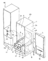
図1〜図12は本発明に係るウォーターサーバーの一実施例を示し、図1は冷水用のウォーターサーバー20と温水用のウォーターサーバー40とを分離した状態で示す斜視図であり、内部機構が見えるように透視的に表されている。図2はバッグインボックス(BIB)の斜視図、図3は冷水用のウォーターサーバー20の概略的断面図である。
1 to 12 show an embodiment of a water server according to the present invention, and FIG. 1 is a perspective view showing the
本発明のウォーターサーバーは、図2(A)に示すようなバッグインボックス(BIB)50を装填して使用する形式のものであり、特に冷却用のウォーターサーバー20に特徴をもたせたものである。図1に示すように、冷却庫本体1には前記バッグインボックス50を前面開口2a側から収納する前開き扉3付きの収納部2を設け、該収納部2に設けられる冷却部4としては、冷却プレートをドーム形状に形成してこれを収納部2の後壁2bの下部の内壁から突出させる。
The water server of the present invention is of a type in which a bag-in-box (BIB) 50 as shown in FIG. 2 (A) is loaded and used, and in particular, the
バッグインボックス50は、周知の如く、図2(B)に示すように、天然水等を給水栓52を備えた柔軟材料からなるバッグ51に封入してこれを段ボール製の外ケース55に収納したものであり、実施例では縦長のブック型のものが示されている。前記バッグ51
に設けられる給水栓52には下向きの注水口53と水平方向に回動自在なコック54とが設けられていて該コック54を所定角度(一般には180゜)回動することにより栓体を開閉するようになっている。
As is well known, the bag-in-
The
本発明において使用されるバッグインボックス50は、外ケース55の前面下部に前記給水栓52を突出させるための開口56を、また、奥壁下部には前記円形の開口部57を、それぞれ容易に形成できるようにするためのミシン目又は破線状切込線等による切り取り部が形成されている。なお、図示例では前記開口56および円形の開口部57を既に形成した状態で示されている。
The bag-in-
前記バッグインボックス50の外ケース55の前壁55aに開口56を形成して給水栓52を引き出すと共に後壁55b下部には前記冷却部4に対応する円形の開口部57を形成し、この状態でバッグインボックス50を前面開口2a側から前記収納部2に装填するようにする。これにより、図3に示すように、冷却部4が開口部57を通じて外ケース55内に挿入される。外ケース55内に冷却部4が挿入されると、前記冷却部4の突出先端で該先端が接触した前記バッグインボックス50の図示しないバッグ(図2(B)中の51)の表面を冷却部の表面形状に倣って冷却部の挿入方向に凹ませた状態にして冷却部4を開口部57を介して対向する前記バッグ51の表面に接触させて内部の水を冷却するようにしたものである。このために、冷却部4は、開口部57を通じて外ケース55内に挿入されたその突出先端が接触したバッグ51の表面を冷却部4の表面形状に倣って冷却部4の挿入方向に凹ませて外ケース55内に挿入されたドーム形状の冷却部4にその全体の表面形状に倣ってバッグ51の表面が接触されるように配置されている。
An
図1に示すように、前記収納部2の底板5には水抜き穴が形成されると共に左右側壁の下部には前記バッグインボックス50を支持する支持レール6が設けられており、前記底板5の下方には水受けトレー7が挿抜自在に設けられている。図において、8は冷却庫本体1の下部に配置されたコンプレッサー等を含む冷却装置である。扉3はデザイン上前面に膨らみをもたせた形状となっており、下部には後に説明する注水機構のためのスライドレバーが配置されている。
As shown in FIG. 1, a drain hole is formed in the bottom plate 5 of the
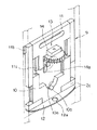
前記収納部2の下部開口縁2cには前記給水栓52を固定するための固定部9が設けられている。この固定部9は、図4に明示するように、前記下部開口縁2cに下端が軸支されていて起立自在になっていると共に前記給水栓52の付け根部が嵌合する凹部10aを有する起立挟持枠10と、該起立挟持枠10にスライド自在に保持されると共に前記給水栓52の付け根部の他方側が嵌合する凹部11aを有するスライド挟持枠11と、で構成されており、前記起立挟持枠10を起立させた状態で前記スライド挟持枠11をスライド降下させることによりギロチン形式で前記給水栓52の付け根部を挟持するようになっている。なお、10bは前記凹部10に形成した位置決め溝であって、この位置決め溝10bに前記給水栓52の注水口53を位置決めすることにより給水栓52が所定の位置に固定されるようになっている。11bは前記スライド挟持枠11の一側上端部に設けたストッパー爪であって、前記スライド挟持枠11をスライド降下させた際に、前記収納部2の前面開口2aの開口縁部に設けたストッパー2d(図8)に係合して前記起立挟持枠10およびスライド挟持枠11が前後方向に倒れないようになっている。12は前記注水口53に対応させた位置に孔12aを穿孔したガイドプレートである。
A fixing portion 9 for fixing the
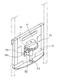
冷水用のウォーターサーバー20には、扉3の表面側から操作することにより間接的に前記給水栓52を開閉操作できる注水機構13(図9)が設けられている。この注水機構13は、図4〜図10に示すように、給水栓52を固定部9で固定することにより該給水栓52のコック54に係合する係合爪14aを有するピニオン14と、扉3の表面側に露呈するように配置されたスライドレバー16の裏面側に配置されたラック15とで構成され、前記スライドレバー16をスライド操作することにより前記ラック15およびピニオン14を介して前記コック54を回動させるようになっている。
The
前記ピニオン14は前記スライド挟持枠11の正面側に配置されており、図10に示すように、下面側には一方の爪をやや長くした二股状の係合爪14aを備えており、スライド挟持枠11がスライド降下して前記給水栓52の首部を挟持すると前記係合爪14aで
前記コック54を挟むようになっている。前記扉3の表面側に形成した操作窓3a(図12)からスライドレバー16の摘み部16aが突出するようになっており、前記ラック15は前記スライドレバー16の裏面側に配置されていて、扉3を閉めるとラック15が前記ピニオン14に噛合するようになっている。なお、図示例では、前記ラック15は平板状をなすスライドレバー16の後端面に形成してあるが、扉3に配置される摘み部16aの高さ位置と前記ピニオン14の配置位置との関係から、スライドレバー16の形状及びラックの形成位置は任意に設計することができる。図1及び図12において、17はコップ載置台である。
The
前記のように構成された冷水用のウォーターサーバー20は単独で設置することもできるが、図1および図12に示すように、冷水用のウォーターサーバー20と温水専用のウォーターサーバー40とを並設することができ、この場合には冷水用のウォーターサーバー20と温水専用のウォーターサーバー40を連結金具30で分離可能に連結する。
Although the
温水専用のウォーターサーバー40は従来形式のものと同様のものであるが、実施例では特に縦長のものとし、バッグインボックス50もこれに対応するように縦長形式のものとして、冷水用のウォーターサーバー20と並設した際に、該冷水用のウォーターサーバー20の上面に載置スペースが形成されるようにしてコップその他の容器類やコーヒー等の飲用物を載置できるようになっている。
The
前記のように、温水専用のウォーターサーバー40は従来形式のものと同様に、バッグインボックス50の給水栓を配管接続部41に接続し、タンク42で加温して給湯口43から温水を注水するものであるが、図12に示すように、実施例では扉45に設けた押しボタン式の摘み46を押し込むことにより給湯口43のコックレバー44を倒して給湯するようになっており、コックレバー44を直接手で操作する従来のものでは熱湯による火傷の危険があったが、その危険を防止できるようにした。前記摘み46は常態においては押し込み不能にロックされていて、該摘み46を横にずらしてロックを解除すると押し込み可能となるようにしてある。
As described above, the hot water
20 冷却用のウォーターサーバー
1 冷却庫本体
2 収納部
3 扉
4 冷却部
5 底板
6 支持レール
8 冷却装置
9 給水栓の固定部
10 起倒挟持枠
10a 凹部
11 スライド挟持枠
11a 凹部
13 注水機構
14 ピニオン
14a 係合爪
15 ラック
16 スライドレバー
30 連結金具
40 温水専用のウォーターサーバー
50 バッグインボックス
51 バッグ
52 給水栓
53 注水口
54 レバー
55 外ケース
56 開口
57 開口部
20
Claims (1)
前記冷却部は、前記開口部を通じて前記外ケース内に挿入されたとき、突出先端が前記開口部を介して対向する前記バッグの表面に接触して該表面を前記冷却部の表面形状に倣って前記冷却部の挿入方向に凹ませることにより、前記外ケース内に挿入された前記冷却部にその全体の表面形状に倣って前記バッグの表面が接触されるように配置されている
ことを特徴とするウォーターサーバー。 A refrigerator main body having a storage portion loaded with a bag-in box in which natural water or the like is enclosed in a bag made of a flexible material provided with a water faucet and stored in an outer case, and the storage portion from its inner wall A cooling part provided so as to protrude, and the cooling part has a cooling plate formed in a dome shape, and the bag-in-box is loaded into the storage part, whereby an outer case of the bag-in-box The natural water in the bag cooled by the contact is inserted into the outer case through the opening formed in a part of the bag and injected from the water inlet of the water tap. In the water server
The cooling unit may, when inserted into the outer casing through the opening, follow the surface to the surface shape of the cooling unit collision out tip in contact with the surface of the bag facing through the opening The bag is arranged so that the surface of the bag is brought into contact with the cooling part inserted into the outer case in accordance with the entire surface shape by being recessed in the insertion direction of the cooling part. And water server.
Priority Applications (1)
| Application Number | Priority Date | Filing Date | Title |
|---|---|---|---|
| JP2009008718A JP4679645B2 (en) | 2009-01-19 | 2009-01-19 | Water server |
Applications Claiming Priority (1)
| Application Number | Priority Date | Filing Date | Title |
|---|---|---|---|
| JP2009008718A JP4679645B2 (en) | 2009-01-19 | 2009-01-19 | Water server |
Related Parent Applications (1)
| Application Number | Title | Priority Date | Filing Date |
|---|---|---|---|
| JP2005150990A Division JP4564405B2 (en) | 2005-05-24 | 2005-05-24 | Water server |
Publications (3)
| Publication Number | Publication Date |
|---|---|
| JP2009078868A JP2009078868A (en) | 2009-04-16 |
| JP2009078868A5 JP2009078868A5 (en) | 2010-09-30 |
| JP4679645B2 true JP4679645B2 (en) | 2011-04-27 |
Family
ID=40653928
Family Applications (1)
| Application Number | Title | Priority Date | Filing Date |
|---|---|---|---|
| JP2009008718A Expired - Fee Related JP4679645B2 (en) | 2009-01-19 | 2009-01-19 | Water server |
Country Status (1)
| Country | Link |
|---|---|
| JP (1) | JP4679645B2 (en) |
Families Citing this family (2)
| Publication number | Priority date | Publication date | Assignee | Title |
|---|---|---|---|---|
| JP5782496B2 (en) * | 2013-11-07 | 2015-09-24 | 山崎産業株式会社 | Liquid cooling device in bag and cooling body |
| JP6294159B2 (en) * | 2014-06-01 | 2018-03-14 | 株式会社千石 | Cooling / heating equipment for PET bottles. |
Citations (3)
| Publication number | Priority date | Publication date | Assignee | Title |
|---|---|---|---|---|
| JP2001526375A (en) * | 1997-12-08 | 2001-12-18 | エンバイロチル インタナショナル リミテッド | Self-cooling fluid container with nested refrigerant chamber and fluid chamber |
| JP2002277132A (en) * | 2001-03-19 | 2002-09-25 | Fujitsu General Ltd | Pet bottle cooler |
| GB2397637A (en) * | 2003-01-21 | 2004-07-28 | Ebac Ltd | Bag-in-Box Containers and Coolers |
-
2009
- 2009-01-19 JP JP2009008718A patent/JP4679645B2/en not_active Expired - Fee Related
Patent Citations (3)
| Publication number | Priority date | Publication date | Assignee | Title |
|---|---|---|---|---|
| JP2001526375A (en) * | 1997-12-08 | 2001-12-18 | エンバイロチル インタナショナル リミテッド | Self-cooling fluid container with nested refrigerant chamber and fluid chamber |
| JP2002277132A (en) * | 2001-03-19 | 2002-09-25 | Fujitsu General Ltd | Pet bottle cooler |
| GB2397637A (en) * | 2003-01-21 | 2004-07-28 | Ebac Ltd | Bag-in-Box Containers and Coolers |
Also Published As
| Publication number | Publication date |
|---|---|
| JP2009078868A (en) | 2009-04-16 |
Similar Documents
| Publication | Publication Date | Title |
|---|---|---|
| JPH10314027A (en) | Lid fixing construction for vessel | |
| KR20050026740A (en) | Refrigerator with dispenser | |
| JP5371704B2 (en) | Beverage server and connection structure for beverage server | |
| EP1925895A2 (en) | Dispenser and Refrigerator Having the Same | |
| JP4679645B2 (en) | Water server | |
| JP4237210B2 (en) | Water server | |
| TW200535061A (en) | Jug comprising a lid | |
| JP4564405B2 (en) | Water server | |
| JP5166219B2 (en) | Liquid container | |
| JP2010042054A (en) | Rice cooker | |
| JP6039927B2 (en) | Beverage dispenser | |
| US2459571A (en) | Cabinet with device for locking an instrument base | |
| JP6948106B2 (en) | Water server and its water supply method | |
| JP2013150788A (en) | Storage container for storing liquid food, such as milk | |
| JP2009269646A (en) | Drinking water feeding apparatus | |
| JP2013138852A (en) | Storage container for storing liquid food such as milk | |
| JP2009001200A (en) | Cup holder | |
| JP3158740U (en) | Liquid container | |
| JP3732196B2 (en) | Liquid insulation container | |
| JP2015030519A (en) | Connector between drinking water packaging bag and water supply pipe in water server | |
| KR100410786B1 (en) | Cup holder having a function of cooling and heating | |
| JP5538482B2 (en) | Water supply machine using a water bag filled with drinking water in a plastic film bag | |
| JP5829862B2 (en) | Bag tray case | |
| JP2006096360A (en) | Liquid spouting device | |
| JP2012046195A (en) | Water cooling machine |
Legal Events
| Date | Code | Title | Description |
|---|---|---|---|
| A621 | Written request for application examination |
Free format text: JAPANESE INTERMEDIATE CODE: A621 Effective date: 20090119 |
|
| A521 | Request for written amendment filed |
Free format text: JAPANESE INTERMEDIATE CODE: A523 Effective date: 20090324 |
|
| A521 | Request for written amendment filed |
Free format text: JAPANESE INTERMEDIATE CODE: A523 Effective date: 20100813 |
|
| A977 | Report on retrieval |
Free format text: JAPANESE INTERMEDIATE CODE: A971007 Effective date: 20100901 |
|
| A131 | Notification of reasons for refusal |
Free format text: JAPANESE INTERMEDIATE CODE: A131 Effective date: 20101012 |
|
| TRDD | Decision of grant or rejection written | ||
| A01 | Written decision to grant a patent or to grant a registration (utility model) |
Free format text: JAPANESE INTERMEDIATE CODE: A01 Effective date: 20110111 |
|
| A01 | Written decision to grant a patent or to grant a registration (utility model) |
Free format text: JAPANESE INTERMEDIATE CODE: A01 |
|
| A61 | First payment of annual fees (during grant procedure) |
Free format text: JAPANESE INTERMEDIATE CODE: A61 Effective date: 20110201 |
|
| R150 | Certificate of patent or registration of utility model |
Ref document number: 4679645 Country of ref document: JP Free format text: JAPANESE INTERMEDIATE CODE: R150 Free format text: JAPANESE INTERMEDIATE CODE: R150 |
|
| FPAY | Renewal fee payment (event date is renewal date of database) |
Free format text: PAYMENT UNTIL: 20140210 Year of fee payment: 3 |
|
| FPAY | Renewal fee payment (event date is renewal date of database) |
Free format text: PAYMENT UNTIL: 20140210 Year of fee payment: 3 |
|
| S111 | Request for change of ownership or part of ownership |
Free format text: JAPANESE INTERMEDIATE CODE: R313113 |
|
| FPAY | Renewal fee payment (event date is renewal date of database) |
Free format text: PAYMENT UNTIL: 20140210 Year of fee payment: 3 |
|
| R350 | Written notification of registration of transfer |
Free format text: JAPANESE INTERMEDIATE CODE: R350 |
|
| R250 | Receipt of annual fees |
Free format text: JAPANESE INTERMEDIATE CODE: R250 |
|
| R250 | Receipt of annual fees |
Free format text: JAPANESE INTERMEDIATE CODE: R250 |
|
| R250 | Receipt of annual fees |
Free format text: JAPANESE INTERMEDIATE CODE: R250 |
|
| R250 | Receipt of annual fees |
Free format text: JAPANESE INTERMEDIATE CODE: R250 |
|
| R250 | Receipt of annual fees |
Free format text: JAPANESE INTERMEDIATE CODE: R250 |
|
| R250 | Receipt of annual fees |
Free format text: JAPANESE INTERMEDIATE CODE: R250 |
|
| R250 | Receipt of annual fees |
Free format text: JAPANESE INTERMEDIATE CODE: R250 |
|
| R250 | Receipt of annual fees |
Free format text: JAPANESE INTERMEDIATE CODE: R250 |
|
| LAPS | Cancellation because of no payment of annual fees |