JP4679017B2 - Vortex eliminator for centrifugal compressor - Google Patents
Vortex eliminator for centrifugal compressor Download PDFInfo
- Publication number
- JP4679017B2 JP4679017B2 JP2001521908A JP2001521908A JP4679017B2 JP 4679017 B2 JP4679017 B2 JP 4679017B2 JP 2001521908 A JP2001521908 A JP 2001521908A JP 2001521908 A JP2001521908 A JP 2001521908A JP 4679017 B2 JP4679017 B2 JP 4679017B2
- Authority
- JP
- Japan
- Prior art keywords
- diffuser
- vortex
- eddy current
- removal
- inlet
- Prior art date
- Legal status (The legal status is an assumption and is not a legal conclusion. Google has not performed a legal analysis and makes no representation as to the accuracy of the status listed.)
- Expired - Fee Related
Links
Images


Classifications
-
- F—MECHANICAL ENGINEERING; LIGHTING; HEATING; WEAPONS; BLASTING
- F04—POSITIVE - DISPLACEMENT MACHINES FOR LIQUIDS; PUMPS FOR LIQUIDS OR ELASTIC FLUIDS
- F04D—NON-POSITIVE-DISPLACEMENT PUMPS
- F04D29/00—Details, component parts, or accessories
- F04D29/40—Casings; Connections of working fluid
- F04D29/42—Casings; Connections of working fluid for radial or helico-centrifugal pumps
- F04D29/44—Fluid-guiding means, e.g. diffusers
- F04D29/441—Fluid-guiding means, e.g. diffusers especially adapted for elastic fluid pumps
- F04D29/444—Bladed diffusers
Description
【0001】
【発明の属する技術分野】
本発明は、遠心圧縮機からの半径方向の高速空気流を受け、次いでその空気をエンジンの環状燃焼器に供給するガスタービンエンジンの構成部品に関する。より具体的には、本発明は、ディフューザと密に組合わされ、空気流を半径方向外向き方向からほぼ軸方向へと向け直すベンド内に配置された渦流除去羽根で構成される、コンパクトな渦流除去装置に関する。
【0002】
【発明の背景】
図1に示すのは、ガスタービンエンジンの遠心圧縮機10及び環状燃焼器12である。圧縮機10は、一般的に、そこを流れるガスを加速し、それによって、ガスの運動エネルギーを増加させるように構成された回転羽根車14を含む。固定環状ディフューザ16は、羽根車14を取り巻き、羽根車14を出る流体流の速度を低下させ、それによってその静圧を増加させる働きをする。ディフューザは、通常、複数の円周方向に間隔をおいた通路18を形成する羽根またはパイプの何れかで構成される。各通路18の断面積は、通常、羽根車14から出る流れを拡散させるために、羽根車14の下流で増加している。
【0003】
羽根型及びパイプ型ディフューザは両方とも、一般的にディフューザ通路18の下流に移行領域20を含み、ディフューザ流路を環状燃焼器12の寸法形状に適合させる。図1に示すように、移行領域20は、ディフューザ16からの半径方向外向きの空気流を受け、この空気流を、燃焼器12の環状入口に向けて後尾方向及びしばしば(図のように)半径方向内向きに向け直す。マニホルド22は、ほぼ直線的な区域24で終わり、この直線的な区域24の内部には、多数の渦流除去羽根26が環状燃焼器12の入口のすぐ上流に配置されている。羽根26は、ディフューザ通路18から出る流れの高い接線方向の速度成分を、より有用な静圧に変換することによって、ディフューザ16から出る流れから、残留円周方向渦流を除去する機能を果たす。その結果、渦流除去羽根26から出て、燃焼器12に向けられる流れは、比較的弱い渦流、低いマッハ数、及び特定の子午線(「噴出」)角度を特徴とし、それらが合わさってより安定性がありかつ効率的な燃焼性能を達成する。多段遠心圧縮機においては、ディフューザ及び移行領域は、各連続する対をなす段の間で使用され、先行段から出る空気流を、後続段に適したレベルまで減速し、渦流除去することができる。
【0004】
図1に示すマニホルド22は、全体として軸対称な自由ベンドを構成しており、2つの(内側及び外側)表面によって境界を定められるベンドも知られているが、この自由ベンドは、1つの(外側)表面によって境界を定められている。マニホルド22内部のベンドに続く直線区域24内部の渦流除去羽根26は、全体的に円錐形の軸対称流路上に配置される。単列の羽根26を示しているが、2列構成も知られている。一般に、羽根26は、ベンドの下流で燃焼器12のすぐ上流、または燃焼器の入口に配置されてきた。
【0005】
図1に示す型式のディフューザ及び渦流除去装置は、多数の成功したガスタービンエンジンで十分に稼働しているが、性能の一層の改善が常に追求されている。主要な関心は、エンジン性能を低下させる圧力損失を減少させることを達成することである。
【0006】
【発明の概要】
本発明は、拡散(二次流)及び摩擦による損失が著しく減少される結果として、エンジン性能全体を向上させる、ガスタービンエンジンの遠心圧縮機のための渦流除去装置を提供する。本発明によれば、渦流除去装置は、一般にディフューザから半径方向外向きに流れるガスを受ける形状にされた入口、該ガスを軸方向下流方向に排出する形状にされた出口、及びその間の弧状通路を有する環状マニホルドを必要とする。先行技術の実施形態とは対照的に、本発明の渦流除去装置は、弧状通路の下流の直線区域内部のみに配置するのに代えて、弧状通路のまさに内部に配置され、ディフューザ装置に密に組合わされる複数の渦流除去羽根を設ける。
【0007】
本発明の渦流除去装置の重要な利点は、エンジン性能を低下させる圧力損失を減少させることである。いかなる特定の理論にもとらわれることを望むものではないが、空気/ガス流をディフューザの半径方向の流れの方向から、圧縮機に要求されるほぼ軸方向の流れの方向へと転向させるベンドの内部に、渦流除去羽根を配置することにより、空気/ガスがディフューザを離れる際の二次流の増幅が減少されるものと思われる。従って、本発明の渦流除去装置は、ベンドによる損失を除去し、接線方向に案内されていないベンドにより生じる可能性がある二次流による損失を減少させるものと思われる。
【0008】
本発明の別の重要な利点は、空気/ガスが、ディフューザ出口から燃焼器プレナムへと移動する全経路長が短くなり、空気/ガスが接触する全表面積が少なくなり、従って、表面接触損失が減少することである。ディフューザ/渦流除去装置はまた、先行技術の装置よりさらにコンパクトであり、エンジンの重量を著しく軽減することが可能になる。
【0009】
本発明のさらに別の重要な観点は、渦流除去羽根をディフューザにごく近接させて弧状通路内部に配置することによって、渦流除去羽根をディフューザに密に組合わせることによる、空気力学的利点が得られると判断されることである。例えば、ディフューザ通路に対して渦流除去羽根を円周方向の適切な相対位置に配置することにより、効率の改善を実現することができる。その結果、本発明は、ディフューザと渦流除去装置のインタフェースにより生じる可能性がある損失をさらに最小にするように、ディフューザと渦流除去装置の適合性を最適化することに関して、設計により大きな柔軟性をもたらす。
【0010】
本発明の他の目的及び利点は、以下の詳細な説明によってより良く理解されるであろう。
【0011】
【発明の実施の形態】
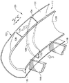
図2は、本発明の好ましい実施形態による、密に組合わされたディフューザと渦流除去装置を断面で示しており、他方、図3は、図2で示す装置の部分斜視図である。図1で示した装置と同様に、本発明の渦流除去装置は、羽根118を備える固定ディフューザ116と共に使用され、羽根118は、遠心圧縮機(図示せず)の羽根車からほぼ半径方向に流れる渦流空気またはガスを、ガスタービンエンジン燃焼器(図示せず)の環状入口112へと向ける。本発明の渦流除去装置はまた、ディフューザ116のすぐ下流に移行領域120を含む。図1に示した装置と同様に、移行領域120は、環状マニホルド122を含み、環状マニホルド122は、ディフューザ116からの半径方向外向きの空気流を受け、この空気流を、燃焼器の入口112に向けて、後尾方向にかつ半径方向内向きに向け直す。マニホルド122が、ディフューザ116からの流れを、約130度から約140度の転向角度がより典型的であると思われるが、下は約90度から上は約180度まで転向させることができることは、本発明の技術的範囲内である。ディフューザ116は、羽根型の構成を有するものとして説明するが、本発明の教示は、パイプ型のディフューザにもまた適用可能である。
【0012】
図2及び図3に示すマニホルド122は、通常、圧縮機のハブ及びケーシングで構成される、それぞれ1対の半径方向内側及び外側表面128及び130によって境界を定められる軸対称ベンドを形成する。マニホルド122によって、燃焼器に入る流れは、比較的弱い渦流、低いマッハ数、及び特定の子午線(「噴出」)角度の特徴を与えられ、それらが合わさってより安定性がありかつ効率的な燃焼性能を達成する。
【0013】
多数の渦流除去羽根126が、マニホルド122の軸対称ベンド内部に配置される。このように、本発明の渦流除去羽根126は、図1の先行技術として示した円錐形の軸対称流路内部のような、ベンドの下流の直線区域内部に配置されるとは限らない。羽根126は、ディフューザ116から出る流れの高い接線方向の速度成分を、より有用な静圧に変換することによって、ディフューザ116から出る流れから、残留円周方向渦流を除去する従来の機能を果たす。しかしながら、羽根126をベンド内部に配置することによって、羽根126は、燃焼器入口112に密に組合わされることに加えて、ディフューザ116にも密に組合わされることが可能になる。本明細書で使用される場合、「密に組合わされる」という 用語は、間隙が、構成部品組立て、及び干渉無しの運転に必要なだけの間隙にまで減少されることを表すのに用いられる。したがって、図2及び図3に示す羽根126は、ディフューザ116に密に組合わされ、他方、図1の羽根26は、ディフューザ16に密に組合わされていない。
【0014】
好ましい実施形態において、渦流除去羽根126は、マニホルド122内部に円周方向に等間隔に配置されている。各羽根126の半径方向内側及び外側端縁は、マニホルド122の2つの軸対称湾曲表面128、130と境を接するように図示されている。各羽根126の形状は、空気またはガスが、同時にかつ徐々に、大きな渦流角度(それがディフューザ116を出る時)を有する半径方向外向き方向から、ほぼ渦流のない子午線噴出方向(それが燃焼器入口112へ入る時)へと転向するように、空気力学的に決定される。この目的のために、図4において最もよく解るように、各羽根126はまた、渦流の除去を促進するマニホルド122内部の弧状のガス流通路表面を与えるように、円周方向に弧状(すなわち、エンジンの中心線に平行な縦方向の線に対して弧状)になっている。各羽根126の半径方向高さは、当業者には明らかなように、羽根126の特定の弧状形状によって定まるであろう。
【0015】
図2ないし図4に示すように、各羽根126の前縁132は、ディフューザ116に密に組合わされ、各羽根126の後縁134は、燃焼器入口112に密に組合わされる。このように、羽根126の各々は、マニホルド122の入口から出口の間のベンドの全長にわたって延びている。図5には、別の実施形態が示されているが、この実施形態では、1つおきの渦流除去羽根126は、マニホルド122の入口から出口の間のベンドの全長にわたって延びているが、1つおきの渦流除去羽根126の間の渦流除去羽根はそのようになっていない。図5に示すように、短い羽根136の前縁138は、ディフューザ116から切り離されており、他方、後縁140は、燃焼器の入口112に密に組合わされたままである。本発明のこの実施形態の利点は、性能の向上を維持しながら、エンジンの軸方向長さをさらに短縮し、重量を軽減することである。
【0016】
図6及び図7に、本発明の渦流除去羽根のさらに2つの別の実施形態を示す。図6には、前縁144に比較してより厚い後縁146を有する渦流除去羽根142を示している。加えて、羽根142の1つに羽根142を貫通する冷却または潤滑管(図示せず)の通路になる孔148が形成されており、このことは、本発明の渦流除去装置をコンパクトにする観点から、必要または有利な場合がある。図7もまた、前縁152に比較して厚い後縁154を有する渦流除去羽根150を示している。図6の実施形態と対照的に、羽根150の1つは、冷却または潤滑管を受け入れるスロット156を備えている。羽根142、150内部に冷却及び潤滑管を組み込むことによって、より均一な排出条件を達成することができ、圧縮機失速マージンに影響を与えるリスクを一層減少させることができる。
【0017】
本発明の重要な観点は、渦流除去羽根126、142及び150を、ディフューザ116に密に組合わせることにより、空気力学的利点を実現することができることである。本発明のこの特徴から生じる少なくとも1つの利点は、隣接するディフューザ羽根118と間の通路に対して、渦流除去羽根126、142及び150を円周方向の適切な相対位置に配置することよって、効率の改善が達成できることである。本発明のこの面の利点は、ベンド全長にわたり延びている渦流除去羽根126、142及び/又は150の数が、ディフューザ通路の数の整数倍である場合、より好ましくは、ディフューザ通路の数に等しい場合に可能であると思われる。ベンド全長にわたり延びている渦流除去羽根126、142及び/又は150の各々が、ディフューザ羽根の1つと円周方向にオフセットしている場合に、エンジン性能が向上することがテストによって確認されている。
【0018】
図8において、このオフセット量が、ディフューザ羽根118及び渦流除去羽根126を後方から前方に見た図によって、「C」で示すエンジンの中心線と共に、概略的に示されている。ディフューザ羽根118の外径と渦流除去羽根126の内径との間のインタフェースに沿って、ピッチ「P」の4分の1の間隔で刻みマークが示されている。4分の1から4分の3の間でのオフセット量を評価したところ、テストしたエンジンについては、渦流除去羽根とディフューザ羽根の間のオフセット量が、4分の1ピッチから2分の1ピッチの間、特にほぼ8分の3ピッチの位置にあるとき最適の結果が得られた。所定のエンジンにおける最適のオフセット量は、圧縮機及び燃焼器の設計が異なれば変化する。しかしながら、ディフューザと渦流除去装置の適合性を最適化する本発明の従来にない能力により、ディフューザと渦流除去装置のインタフェースにより生じる可能性がある損失を最小限にすることに関して、より大きな設計上の柔軟性をもたらす。
【0019】
本発明を、好ましい実施形態及び別の実施形態について説明してきたが、当業者が他の形態を採用し得ることは明白である。例えば、本発明の渦流除去装置は多段遠心圧縮機に使用して、各対をなす隣接段の間に配置することができる。
【0020】
本発明の技術的範囲は、冒頭の特許請求の範囲のみによって限定されるものであり、特許請求の範囲に記載された符号は、理解容易のためであってなんら発明の技術的範囲を実施例に限縮するものではない。
【図面の簡単な説明】
【図1】 先行技術におけるガスタービンエンジンの遠心圧縮機のためのディフューザ及び渦流除去装置の部分断面図。
【図2】 本発明によるディフューザ及び渦流除去装置の断面図。
【図3】 本発明による渦流除去装置の斜視図。
【図4】 図2及び図3に示す渦流除去羽根の羽根のみの斜視図。
【図5】 図2ないし図4に示す渦流除去羽根に対する別の実施形態の羽根のみの斜視図。
【図6】 図2ないし図4に示す渦流除去羽根に対する別の実施形態の羽根のみの斜視図。
【図7】 図2ないし図4に示す渦流除去羽根に対する別の実施形態の羽根のみの斜視図。
【図8】 図2及び図3に示すディフューザ及び渦流除去羽根の後方から前方に見た図。
【符号の説明】
112 燃焼器入口
116 ディフューザ
118 ディフューザ羽根
120 移行領域
122 マニホルド
124 弧状通路
126 渦流除去羽根
128 半径方向内側表面
130 半径方向外側表面
132 前縁
134 後縁[0001]
BACKGROUND OF THE INVENTION
The present invention relates to a gas turbine engine component that receives a high-speed radial airflow from a centrifugal compressor and then supplies that air to the engine's annular combustor. More specifically, the present invention is a compact eddy current comprised of vortex removal vanes that are intimately combined with a diffuser and arranged in a bend that redirects the air flow from a radially outward direction to a substantially axial direction. The present invention relates to a removing device.
[0002]
BACKGROUND OF THE INVENTION
Shown in FIG. 1 is a
[0003]
Both vane and pipe diffusers generally include a
[0004]
The
[0005]
Although the type of diffuser and vortex remover of the type shown in FIG. 1 has worked well on many successful gas turbine engines, further improvements in performance are constantly sought. A major concern is to achieve a reduction in pressure loss that degrades engine performance.
[0006]
Summary of the Invention
The present invention provides a vortex removal device for a centrifugal compressor of a gas turbine engine that improves overall engine performance as a result of significantly reduced losses due to diffusion (secondary flow) and friction. In accordance with the present invention, an eddy current removal device generally includes an inlet configured to receive a gas flowing radially outward from a diffuser, an outlet configured to discharge the gas axially downstream, and an arcuate passage therebetween. Requires an annular manifold. In contrast to the prior art embodiments, the vortex removal device of the present invention is placed just inside the arcuate passage instead of being placed only inside the straight section downstream of the arcuate passage, and is tightly connected to the diffuser device. A plurality of vortex removal blades to be combined are provided.
[0007]
An important advantage of the eddy current removal apparatus of the present invention is that it reduces pressure losses that degrade engine performance. While not wishing to be bound by any particular theory, the interior of the bend that diverts the air / gas flow from the radial flow direction of the diffuser to the nearly axial flow direction required by the compressor. In addition, the placement of vortex removal vanes is believed to reduce secondary flow amplification as air / gas leaves the diffuser. Accordingly, the eddy current removal device of the present invention is believed to eliminate bend losses and reduce secondary flow losses that may be caused by bends that are not guided tangentially.
[0008]
Another important advantage of the present invention is that the total path length that air / gas travels from the diffuser outlet to the combustor plenum is reduced, and the total surface area that the air / gas contacts is reduced, thus reducing surface contact loss. It is to decrease. The diffuser / vortex eliminator is also more compact than prior art devices, allowing for a significant reduction in engine weight.
[0009]
Yet another important aspect of the present invention is that aerodynamic advantages are obtained by closely combining the vortex shedding vanes with the diffuser by placing the vortex shedding vanes in close proximity to the diffuser and within the arcuate passage. It is to be judged. For example, improvement in efficiency can be realized by arranging the vortex removal blades at appropriate relative positions in the circumferential direction with respect to the diffuser passage. As a result, the present invention provides greater design flexibility with regard to optimizing the compatibility of the diffuser and vortex remover to further minimize the losses that may be caused by the diffuser and vortex remover interface. Bring.
[0010]
Other objects and advantages of this invention will be better appreciated from the following detailed description.
[0011]
DETAILED DESCRIPTION OF THE INVENTION
FIG. 2 shows in cross-section a closely combined diffuser and vortex remover according to a preferred embodiment of the present invention, while FIG. 3 is a partial perspective view of the device shown in FIG. Similar to the apparatus shown in FIG. 1, the eddy current removal apparatus of the present invention is used in conjunction with a
[0012]
The manifold 122 shown in FIGS. 2 and 3 forms an axisymmetric bend, typically bounded by a pair of radially inner and
[0013]
A number of
[0014]
In a preferred embodiment, the
[0015]
As shown in FIGS. 2-4, the
[0016]
6 and 7 show two further embodiments of the vortex removal blade of the present invention. FIG. 6 shows a
[0017]
An important aspect of the present invention is that aerodynamic advantages can be realized by tightly combining the
[0018]
In FIG. 8, this offset amount is schematically shown along with the engine centerline indicated by “C” by a view of the
[0019]
While the invention has been described in terms of a preferred and alternative embodiment, it is apparent that other forms can be adopted by one skilled in the art. For example, the eddy current removal apparatus of the present invention can be used in a multi-stage centrifugal compressor and disposed between adjacent pairs of adjacent stages.
[0020]
The technical scope of the present invention is limited only by the scope of the appended claims, and the reference signs in the claims are provided for ease of understanding and are not intended to limit the technical scope of the invention. It is not limited to.
[Brief description of the drawings]
FIG. 1 is a partial cross-sectional view of a diffuser and vortex removal device for a centrifugal compressor of a gas turbine engine in the prior art.
FIG. 2 is a cross-sectional view of a diffuser and a vortex removal device according to the present invention.
FIG. 3 is a perspective view of a vortex removing device according to the present invention.
4 is a perspective view of only a blade of the vortex removal blade shown in FIGS. 2 and 3. FIG.
FIG. 5 is a perspective view of only a blade of another embodiment for the vortex removal blade shown in FIGS. 2 to 4;
6 is a perspective view of only a blade according to another embodiment with respect to the vortex removal blade shown in FIGS. 2 to 4; FIG.
7 is a perspective view of only a blade of another embodiment for the vortex removal blade shown in FIGS. 2 to 4; FIG.
8 is a view of the diffuser and the vortex removal blade shown in FIGS. 2 and 3 as seen from the rear to the front. FIG.
[Explanation of symbols]
112
Claims (10)
ディフューザ(116)から半径方向外向きに流れるガスを受ける形状にされた入口、該ガスを軸方向下流方向に排出する形状にされた出口、及びその間の弧状通路(124)を有する環状マニホルド(122)と、
前記弧状通路(124)内部にあり前記ディフューザとごく近接した複数の渦流除去羽根(126、136、142、150)と、
を含み、
前記渦流除去羽根(126、136、142、150)の各々が、前記ディフューザ(116)に密に組合わされた前縁(132、144、152)と、前記燃焼器の入口(112)に密に組合わされた後縁(134、140、146、154)とを備え、前記前縁と前記ディフューザとの間の間隙及び前記後縁と前記燃焼器の入口との間の間隙が、構成部品組立て及び干渉無しの運転に必要とされる間隙だけにまで減少されていることを特徴とする渦流除去装置。 A vortex removal device for a gas turbine engine for receiving an air flow from a centrifugal compressor (10) and supplying it to a combustor ,
Annular manifold (122) having an inlet configured to receive gas flowing radially outward from diffuser (116), an outlet configured to discharge the gas axially downstream, and an arcuate passage (124) therebetween. )When,
A plurality of swirl removal vanes (126, 136, 142, 150) within the arcuate passage (124) and in close proximity to the diffuser;
Including
Dense Each pre Kiuzu stream removed vanes (126,136,142,150) has an edge (132,144,152) before being closely combined with the diffuser (116), the inlet (112) of the combustor And a gap between the leading edge and the diffuser and a gap between the trailing edge and the combustor inlet are the component assemblies. And a vortex removal device characterized in that it is reduced to only the gaps required for operation without interference .
Applications Claiming Priority (3)
| Application Number | Priority Date | Filing Date | Title |
|---|---|---|---|
| US09/390,876 US6279322B1 (en) | 1999-09-07 | 1999-09-07 | Deswirler system for centrifugal compressor |
| US09/390,876 | 1999-09-07 | ||
| PCT/US2000/021941 WO2001018404A1 (en) | 1999-09-07 | 2000-08-10 | Deswirler system for centrifugal compressor |
Publications (3)
| Publication Number | Publication Date |
|---|---|
| JP2003508690A JP2003508690A (en) | 2003-03-04 |
| JP2003508690A5 JP2003508690A5 (en) | 2007-10-11 |
| JP4679017B2 true JP4679017B2 (en) | 2011-04-27 |
Family
ID=23544313
Family Applications (1)
| Application Number | Title | Priority Date | Filing Date |
|---|---|---|---|
| JP2001521908A Expired - Fee Related JP4679017B2 (en) | 1999-09-07 | 2000-08-10 | Vortex eliminator for centrifugal compressor |
Country Status (14)
| Country | Link |
|---|---|
| US (1) | US6279322B1 (en) |
| EP (1) | EP1214522B1 (en) |
| JP (1) | JP4679017B2 (en) |
| KR (1) | KR100767886B1 (en) |
| CN (1) | CN1214191C (en) |
| AU (1) | AU759980B2 (en) |
| CA (1) | CA2384017C (en) |
| DE (1) | DE60016937T2 (en) |
| HK (1) | HK1051715A1 (en) |
| IL (1) | IL148394A0 (en) |
| MX (1) | MXPA02002479A (en) |
| NO (1) | NO20021110L (en) |
| TR (1) | TR200200584T2 (en) |
| WO (1) | WO2001018404A1 (en) |
Families Citing this family (53)
| Publication number | Priority date | Publication date | Assignee | Title |
|---|---|---|---|---|
| US7025566B2 (en) * | 2003-11-04 | 2006-04-11 | Pratt & Whitney Canada Corp. | Hybrid vane island diffuser |
| US7506511B2 (en) * | 2003-12-23 | 2009-03-24 | Honeywell International Inc. | Reduced exhaust emissions gas turbine engine combustor |
| US7442006B2 (en) * | 2005-08-15 | 2008-10-28 | Honeywell International Inc. | Integral diffuser and deswirler with continuous flow path deflected at assembly |
| US7500364B2 (en) | 2005-11-22 | 2009-03-10 | Honeywell International Inc. | System for coupling flow from a centrifugal compressor to an axial combustor for gas turbines |
| US7870739B2 (en) * | 2006-02-02 | 2011-01-18 | Siemens Energy, Inc. | Gas turbine engine curved diffuser with partial impingement cooling apparatus for transitions |
| US20070183890A1 (en) * | 2006-02-09 | 2007-08-09 | Honeywell International, Inc. | Leaned deswirl vanes behind a centrifugal compressor in a gas turbine engine |
| US7600370B2 (en) | 2006-05-25 | 2009-10-13 | Siemens Energy, Inc. | Fluid flow distributor apparatus for gas turbine engine mid-frame section |
| US7717672B2 (en) * | 2006-08-29 | 2010-05-18 | Honeywell International Inc. | Radial vaned diffusion system with integral service routings |
| FR2920032B1 (en) * | 2007-08-13 | 2014-08-22 | Snecma | DIFFUSER OF A TURBOMACHINE |
| FR2920033B1 (en) * | 2007-08-13 | 2014-08-22 | Snecma | TURBOMACHINE WITH DIFFUSER |
| FR2922939B1 (en) * | 2007-10-26 | 2014-04-25 | Snecma | TURBOMACHINE COMPRISING A DIFFUSER |
| US7975506B2 (en) | 2008-02-20 | 2011-07-12 | Trane International, Inc. | Coaxial economizer assembly and method |
| US8037713B2 (en) | 2008-02-20 | 2011-10-18 | Trane International, Inc. | Centrifugal compressor assembly and method |
| US7856834B2 (en) * | 2008-02-20 | 2010-12-28 | Trane International Inc. | Centrifugal compressor assembly and method |
| US9353765B2 (en) | 2008-02-20 | 2016-05-31 | Trane International Inc. | Centrifugal compressor assembly and method |
| FR2927951B1 (en) * | 2008-02-27 | 2011-08-19 | Snecma | DIFFUSER-RECTIFIER ASSEMBLY FOR A TURBOMACHINE |
| US8272832B2 (en) * | 2008-04-17 | 2012-09-25 | Honeywell International Inc. | Centrifugal compressor with surge control, and associated method |
| FR2931515B1 (en) * | 2008-05-22 | 2014-07-18 | Snecma | TURBOMACHINE WITH DIFFUSER |
| US8438854B2 (en) * | 2008-05-23 | 2013-05-14 | Honeywell International Inc. | Pre-diffuser for centrifugal compressor |
| US8113002B2 (en) * | 2008-10-17 | 2012-02-14 | General Electric Company | Combustor burner vanelets |
| FR2941742B1 (en) * | 2009-02-05 | 2011-08-19 | Snecma | DIFFUSER-RECTIFIER ASSEMBLY FOR A TURBOMACHINE |
| FR2955364B1 (en) | 2010-01-19 | 2012-11-16 | Snecma | DIFFUSER-RECTIFIER CONNECTION FOR A CENTRIFUGAL COMPRESSOR |
| DE102010023816A1 (en) | 2010-06-15 | 2011-12-15 | Rolls-Royce Deutschland Ltd & Co Kg | Gas turbine combustor assembly |
| FR2961867B1 (en) * | 2010-06-24 | 2014-06-13 | Snecma | AIR COLLECTION THROUGH THE DIFFUSER OF A CENTRIFUGAL COMPRESSOR OF A TURBOMACHINE |
| US9347328B2 (en) * | 2010-08-09 | 2016-05-24 | Siemens Energy, Inc. | Compressed air plenum for a gas turbine engine |
| DE102011108887A1 (en) * | 2011-07-28 | 2013-01-31 | Rolls-Royce Deutschland Ltd & Co Kg | Gas turbine centripetal ring combustion chamber and method for flow guidance |
| US20140338360A1 (en) * | 2012-09-21 | 2014-11-20 | United Technologies Corporation | Bleed port ribs for turbomachine case |
| WO2014137430A1 (en) * | 2013-03-08 | 2014-09-12 | Rolls-Royce North American Technologies, Inc. | Gas turbine engine centrifugal compressor with seal between two diffuser parts |
| US9726185B2 (en) | 2013-05-14 | 2017-08-08 | Honeywell International Inc. | Centrifugal compressor with casing treatment for surge control |
| US9134029B2 (en) | 2013-09-12 | 2015-09-15 | Siemens Energy, Inc. | Radial midframe baffle for can-annular combustor arrangement having tangentially oriented combustor cans |
| US9528706B2 (en) | 2013-12-13 | 2016-12-27 | Siemens Energy, Inc. | Swirling midframe flow for gas turbine engine having advanced transitions |
| US10557358B2 (en) * | 2015-02-06 | 2020-02-11 | United Technologies Corporation | Gas turbine engine containment structures |
| DE102015219556A1 (en) * | 2015-10-08 | 2017-04-13 | Rolls-Royce Deutschland Ltd & Co Kg | Diffuser for radial compressor, centrifugal compressor and turbo machine with centrifugal compressor |
| DE102015220333A1 (en) | 2015-10-19 | 2017-04-20 | Rolls-Royce Deutschland Ltd & Co Kg | Device for adjusting a gap between the housing of an impeller and the impeller in a centrifugal compressor and a turbomachine |
| US10570925B2 (en) | 2015-10-27 | 2020-02-25 | Pratt & Whitney Canada Corp. | Diffuser pipe with splitter vane |
| US9926942B2 (en) | 2015-10-27 | 2018-03-27 | Pratt & Whitney Canada Corp. | Diffuser pipe with vortex generators |
| US10030581B2 (en) | 2016-02-24 | 2018-07-24 | Pratt & Whitney Canada Corp. | Air intake with scroll portion and strutted portion for gas turbine engine |
| US10087839B2 (en) | 2016-02-24 | 2018-10-02 | Pratt & Whitney Canada Corp. | Air intake for turboprop engine |
| US10544693B2 (en) * | 2016-06-15 | 2020-01-28 | Honeywell International Inc. | Service routing configuration for a gas turbine engine diffuser system |
| US10898627B2 (en) * | 2017-01-12 | 2021-01-26 | California Cardiac Solutions, Inc. | Ventricular assist device |
| US10519868B2 (en) | 2017-02-14 | 2019-12-31 | Honeywell International Inc. | System and method for cleaning cooling passages of a combustion chamber |
| US10718222B2 (en) | 2017-03-27 | 2020-07-21 | General Electric Company | Diffuser-deswirler for a gas turbine engine |
| US11536456B2 (en) | 2017-10-24 | 2022-12-27 | General Electric Company | Fuel and air injection handling system for a combustor of a rotating detonation engine |
| KR102000258B1 (en) * | 2018-12-20 | 2019-07-15 | 한국건설기술연구원 | 2 step radial blower |
| US10989219B2 (en) * | 2019-02-04 | 2021-04-27 | Honeywell International Inc. | Diffuser assemblies for compression systems |
| US11098730B2 (en) * | 2019-04-12 | 2021-08-24 | Rolls-Royce Corporation | Deswirler assembly for a centrifugal compressor |
| US11939070B2 (en) | 2020-02-21 | 2024-03-26 | General Electric Company | Engine-mounting links that have an adjustable inclination angle |
| CN111894760B (en) * | 2020-07-13 | 2022-11-15 | 潍坊联信增压器股份有限公司 | Turbojet engine capable of eliminating tail rotating vortex |
| US11441516B2 (en) | 2020-07-14 | 2022-09-13 | Rolls-Royce North American Technologies Inc. | Centrifugal compressor assembly for a gas turbine engine with deswirler having sealing features |
| US11286952B2 (en) | 2020-07-14 | 2022-03-29 | Rolls-Royce Corporation | Diffusion system configured for use with centrifugal compressor |
| US11578654B2 (en) | 2020-07-29 | 2023-02-14 | Rolls-Royce North American Technologies Inc. | Centrifical compressor assembly for a gas turbine engine |
| CN114593089A (en) * | 2022-01-26 | 2022-06-07 | 北京盈天航空动力科技有限公司 | V-shaped meridian flow passage diffuser of micro turbojet engine |
| CN114635876B (en) * | 2022-05-23 | 2022-09-20 | 宁波威孚天力增压技术股份有限公司 | Centrifugal compressor with air entraining mechanism and turbocharger |
Family Cites Families (19)
| Publication number | Priority date | Publication date | Assignee | Title |
|---|---|---|---|---|
| US2681760A (en) | 1949-02-26 | 1954-06-22 | Curtiss Wright Corp | Centrifugal compressor |
| GB884507A (en) | 1960-06-02 | 1961-12-13 | Neu Sa | Improvements in or relating to centrifugal compressors |
| US3333762A (en) | 1966-11-16 | 1967-08-01 | United Aircraft Canada | Diffuser for centrifugal compressor |
| US3719430A (en) * | 1971-08-24 | 1973-03-06 | Gen Electric | Diffuser |
| US3861826A (en) | 1972-08-14 | 1975-01-21 | Caterpillar Tractor Co | Cascade diffuser having thin, straight vanes |
| US4027997A (en) * | 1975-12-10 | 1977-06-07 | General Electric Company | Diffuser for a centrifugal compressor |
| US4100732A (en) * | 1976-12-02 | 1978-07-18 | General Electric Company | Centrifugal compressor advanced dump diffuser |
| SE8601577L (en) | 1985-04-29 | 1986-10-30 | Teledyne Ind | DIFFUSOR SYSTEM INCLUDING A CENTRIFUGAL COMPRESSOR AND PROCEDURE FOR MANUFACTURING ITS SAME |
| US5011371A (en) | 1987-04-29 | 1991-04-30 | General Motors Corporation | Centrifugal compressor/pump with fluid dynamically variable geometry diffuser |
| US5062262A (en) * | 1988-12-28 | 1991-11-05 | Sundstrand Corporation | Cooling of turbine nozzles |
| US5101620A (en) * | 1988-12-28 | 1992-04-07 | Sundstrand Corporation | Annular combustor for a turbine engine without film cooling |
| US4981018A (en) * | 1989-05-18 | 1991-01-01 | Sundstrand Corporation | Compressor shroud air bleed passages |
| US4979361A (en) | 1989-07-13 | 1990-12-25 | United Technologies Corporation | Stepped diffuser |
| US5129224A (en) * | 1989-12-08 | 1992-07-14 | Sundstrand Corporation | Cooling of turbine nozzle containment ring |
| US5303543A (en) * | 1990-02-08 | 1994-04-19 | Sundstrand Corporation | Annular combustor for a turbine engine with tangential passages sized to provide only combustion air |
| JP3010806B2 (en) * | 1991-07-02 | 2000-02-21 | ソニー株式会社 | LCD projector |
| US5335501A (en) | 1992-11-16 | 1994-08-09 | General Electric Company | Flow spreading diffuser |
| JP3110205B2 (en) | 1993-04-28 | 2000-11-20 | 株式会社日立製作所 | Centrifugal compressor and diffuser with blades |
| US5680767A (en) | 1995-09-11 | 1997-10-28 | General Electric Company | Regenerative combustor cooling in a gas turbine engine |
-
1999
- 1999-09-07 US US09/390,876 patent/US6279322B1/en not_active Expired - Lifetime
-
2000
- 2000-08-10 WO PCT/US2000/021941 patent/WO2001018404A1/en active IP Right Grant
- 2000-08-10 CA CA002384017A patent/CA2384017C/en not_active Expired - Fee Related
- 2000-08-10 CN CNB008149496A patent/CN1214191C/en not_active Expired - Fee Related
- 2000-08-10 DE DE60016937T patent/DE60016937T2/en not_active Expired - Lifetime
- 2000-08-10 EP EP00955443A patent/EP1214522B1/en not_active Expired - Lifetime
- 2000-08-10 JP JP2001521908A patent/JP4679017B2/en not_active Expired - Fee Related
- 2000-08-10 KR KR1020027002962A patent/KR100767886B1/en not_active IP Right Cessation
- 2000-08-10 AU AU67651/00A patent/AU759980B2/en not_active Ceased
- 2000-08-10 TR TR2002/00584T patent/TR200200584T2/en unknown
- 2000-08-10 IL IL14839400A patent/IL148394A0/en not_active IP Right Cessation
- 2000-08-10 MX MXPA02002479A patent/MXPA02002479A/en active IP Right Grant
-
2002
- 2002-03-06 NO NO20021110A patent/NO20021110L/en not_active Application Discontinuation
-
2003
- 2003-06-03 HK HK03103937A patent/HK1051715A1/en not_active IP Right Cessation
Also Published As
| Publication number | Publication date |
|---|---|
| KR20020039343A (en) | 2002-05-25 |
| EP1214522A1 (en) | 2002-06-19 |
| MXPA02002479A (en) | 2002-08-28 |
| US6279322B1 (en) | 2001-08-28 |
| CA2384017A1 (en) | 2001-03-15 |
| AU6765100A (en) | 2001-04-10 |
| TR200200584T2 (en) | 2002-07-22 |
| DE60016937T2 (en) | 2005-12-15 |
| CA2384017C (en) | 2008-11-18 |
| IL148394A0 (en) | 2002-09-12 |
| AU759980B2 (en) | 2003-05-01 |
| NO20021110D0 (en) | 2002-03-06 |
| NO20021110L (en) | 2002-05-06 |
| CN1384902A (en) | 2002-12-11 |
| DE60016937D1 (en) | 2005-01-27 |
| JP2003508690A (en) | 2003-03-04 |
| HK1051715A1 (en) | 2003-08-15 |
| EP1214522B1 (en) | 2004-12-22 |
| KR100767886B1 (en) | 2007-10-17 |
| WO2001018404A1 (en) | 2001-03-15 |
| CN1214191C (en) | 2005-08-10 |
Similar Documents
| Publication | Publication Date | Title |
|---|---|---|
| JP4679017B2 (en) | Vortex eliminator for centrifugal compressor | |
| US6863496B2 (en) | Fan and shroud assembly | |
| US8235648B2 (en) | Diffuser with enhanced surge margin | |
| CA2528668C (en) | Rotor assembly with cooling air deflectors and method | |
| US4530639A (en) | Dual-entry centrifugal compressor | |
| CA2701312C (en) | Centrifugal compressor vane diffuser wall contouring | |
| JP3564420B2 (en) | gas turbine | |
| JP2009062976A (en) | Turbomachine with diffuser | |
| JPS6130160B2 (en) | ||
| PL200472B1 (en) | Compressor, compressor's housing and compressor's impeller vane | |
| JP4820492B2 (en) | Method and apparatus for supplying a cooling air flow in a turbine engine | |
| KR20100080427A (en) | Methods, systems and/or apparatus relating to inducers for turbine engines | |
| CA2893755A1 (en) | Diffuser pipe with splitter vane | |
| EP3832144B1 (en) | Diffuser pipe with radially-outward exit | |
| EP2554793A2 (en) | Inter-turbine ducts with guide vanes of a gas turbine engine | |
| US10823195B2 (en) | Diffuser pipe with non-axisymmetric end wall | |
| CA3081250A1 (en) | Diffuser pipe with exit flare | |
| CN1434894A (en) | Axial flow turbine type rotor mechanical device for elastic fluid | |
| US11268536B1 (en) | Impeller exducer cavity with flow recirculation | |
| JP2023164527A (en) | Impeller for centrifugal compressor and centrifugal compressor | |
| CN117917502A (en) | Turbine engine with compressor having flow director |
Legal Events
| Date | Code | Title | Description |
|---|---|---|---|
| A521 | Request for written amendment filed |
Free format text: JAPANESE INTERMEDIATE CODE: A523 Effective date: 20070809 |
|
| A621 | Written request for application examination |
Free format text: JAPANESE INTERMEDIATE CODE: A621 Effective date: 20070809 |
|
| A131 | Notification of reasons for refusal |
Free format text: JAPANESE INTERMEDIATE CODE: A131 Effective date: 20100601 |
|
| A601 | Written request for extension of time |
Free format text: JAPANESE INTERMEDIATE CODE: A601 Effective date: 20100827 |
|
| RD02 | Notification of acceptance of power of attorney |
Free format text: JAPANESE INTERMEDIATE CODE: A7422 Effective date: 20100827 |
|
| RD04 | Notification of resignation of power of attorney |
Free format text: JAPANESE INTERMEDIATE CODE: A7424 Effective date: 20100827 |
|
| A602 | Written permission of extension of time |
Free format text: JAPANESE INTERMEDIATE CODE: A602 Effective date: 20100906 |
|
| A521 | Request for written amendment filed |
Free format text: JAPANESE INTERMEDIATE CODE: A523 Effective date: 20101130 |
|
| TRDD | Decision of grant or rejection written | ||
| A01 | Written decision to grant a patent or to grant a registration (utility model) |
Free format text: JAPANESE INTERMEDIATE CODE: A01 Effective date: 20110105 |
|
| A01 | Written decision to grant a patent or to grant a registration (utility model) |
Free format text: JAPANESE INTERMEDIATE CODE: A01 |
|
| A61 | First payment of annual fees (during grant procedure) |
Free format text: JAPANESE INTERMEDIATE CODE: A61 Effective date: 20110201 |
|
| R150 | Certificate of patent or registration of utility model |
Free format text: JAPANESE INTERMEDIATE CODE: R150 |
|
| FPAY | Renewal fee payment (event date is renewal date of database) |
Free format text: PAYMENT UNTIL: 20140210 Year of fee payment: 3 |
|
| R250 | Receipt of annual fees |
Free format text: JAPANESE INTERMEDIATE CODE: R250 |
|
| R250 | Receipt of annual fees |
Free format text: JAPANESE INTERMEDIATE CODE: R250 |
|
| R250 | Receipt of annual fees |
Free format text: JAPANESE INTERMEDIATE CODE: R250 |
|
| R250 | Receipt of annual fees |
Free format text: JAPANESE INTERMEDIATE CODE: R250 |
|
| LAPS | Cancellation because of no payment of annual fees |