JP4677342B2 - Printing apparatus, control method, program - Google Patents
Printing apparatus, control method, program Download PDFInfo
- Publication number
- JP4677342B2 JP4677342B2 JP2005368546A JP2005368546A JP4677342B2 JP 4677342 B2 JP4677342 B2 JP 4677342B2 JP 2005368546 A JP2005368546 A JP 2005368546A JP 2005368546 A JP2005368546 A JP 2005368546A JP 4677342 B2 JP4677342 B2 JP 4677342B2
- Authority
- JP
- Japan
- Prior art keywords
- printing
- sheet
- case binding
- job
- user
- Prior art date
- Legal status (The legal status is an assumption and is not a legal conclusion. Google has not performed a legal analysis and makes no representation as to the accuracy of the status listed.)
- Active
Links
Images


Description
本発明は、くるみ製本の中紙として利用される印刷用紙に印刷を行う印刷装置、制御方法、プログラム等に関する。 The present invention relates to a printing device for printing on printing paper to be used as inner sheets of the case binding, a control method, a program, and the like.
近年、デジタル複合機において、デジタル画像処理による面つけ機能を利用した製本印刷(小冊子印刷)が可能となり、小冊子印刷を中綴じするシート処理装置が提案されている。 In recent years, bookbinding printing (booklet printing) using an imposition function based on digital image processing has become possible in digital multi-function peripherals, and a sheet processing apparatus for saddle stitching booklet printing has been proposed.
このような中綴じ製本機能付きシート処理装置にて実現できる処理は、簡易的な製本処理である。今後は、このような小冊子印刷等の簡易的な製本処理の他にも、本来の製本、例えば、印刷物に糊付け処理を施す糊付け製本処理等の本格的な製本処理が要求される可能性が考えられる。このような、糊付け製本機能を提案するべく、特開2002−293060号公報(特許文献1)に示される糊付け製本装置のような構成も検討されつつある。 A process that can be realized by such a sheet processing apparatus with a saddle stitch bookbinding function is a simple bookbinding process. In the future, in addition to simple bookbinding processing such as booklet printing, there is a possibility that full-scale bookbinding processing such as original bookbinding, for example, gluing bookbinding processing that applies gluing processing to printed matter may be required. It is done. In order to propose such a gluing bookbinding function, a configuration like a gluing bookbinding apparatus disclosed in Japanese Patent Application Laid-Open No. 2002-293060 (Patent Document 1) is being studied.
このような糊付け製本装置は、デジタル複合機と同等な大きさか、それ以上のサイズになる可能性が考えられる。このような大きなサイズの糊付け製本機は、コストが高くなり占有面積が大きくなる可能性がある。故に、コピー機室などの専用スペースを設けているユーザ以外は導入が難しくなる事が予想される。 There is a possibility that such a gluing bookbinding apparatus has a size equivalent to or larger than that of a digital multifunction peripheral. Such a large size glue binding machine can be costly and occupy a large area. Therefore, it is expected that the introduction will be difficult except for users who have a dedicated space such as a copy machine room.
そこで、この糊付け製本機器サイズを小さくすることが検討されつつある。サイズを小さくすることにより、コストも低くなり、占有面積も少なくなる。このように、この糊付け製本機器サイズを小さくすることにより、専用スペース等が確保できないユーザであっても、糊付け製本機を備えた機器の導入が可能となる等のことが期待される。
しかしながら、糊付け製本機のサイズを小さくすることを考えてみると、以下のような制限事項が発生することが予想される。 However, when considering reducing the size of the gluing bookbinding machine, the following restrictions are expected to occur.
(1)ラージサイズ(A3サイズ、B4サイズ)の製本が行えなくなる。 (1) Binding of large size (A3 size, B4 size) cannot be performed.
(2)一度に糊付け処理可能な枚数に関しても同様に、限られた枚数に限定されてしまう。 (2) Similarly, the number of sheets that can be glued at once is limited to a limited number.
(3)紙の種類により、一度に糊付け処理可能な枚数も変化してしまう。例えば、厚紙の場合は紙の厚みが増える分だけ糊付け可能な枚数が少なくなる。 (3) Depending on the type of paper, the number of sheets that can be glued at a time also changes. For example, in the case of thick paper, the number of sheets that can be glued decreases as the paper thickness increases.
なお、市場を見ると、ラージサイズ(A3サイズ、B4サイズ)の製本よりも、スモールサイズ(A4、LTRサイズ以下)の製本のニーズが圧倒的に高く、ラージサイズ(A3サイズ、B4サイズ)の製本のニーズは低いと思われる。一方、例えば、通常のデジタル複合機では、ラージサイズの印刷にも対応している。 Looking at the market, the need for small size (A4, LTR size or smaller) bookbinding is overwhelmingly higher than that for large size (A3 size, B4 size) bookbinding, and large size (A3 size, B4 size) The need for binding is low. On the other hand, for example, an ordinary digital multi-function peripheral also supports large size printing.
従って、例えば、このような小サイズのデジタル複合機等の画像形成装置や画像形成システムにおいて、糊付け製本を実現できるようになる事を想定してみると、ユーザがラージサイズの製本も可能であるかのように錯覚してしまう可能性があると思われる。 Therefore, for example, assuming that it becomes possible to realize glue binding in an image forming apparatus or image forming system such as a small-sized digital multifunction peripheral, the user can also perform large-size binding. There seems to be a possibility of illusion.
加えて、例えば、このようなユーザの勘違いが原因で、ラージサイズの用紙への印刷を指定してしまい、結局、印刷は可能であっても、上記(1)の制限により製本時にエラーとなる等の不具合が生じる可能性がある。このように、ユーザの手間や資源を無駄にしてしまう等の問題が発生しうる。 In addition, for example, due to such misunderstanding of the user, printing on large size paper is designated, and eventually, even if printing is possible, an error occurs during bookbinding due to the restriction (1) above. Such a problem may occur. Thus, problems such as wasting user's effort and resources may occur.
また、例えば、上記(2)(3)に示した処理可能な制限枚数については、該制限枚数を把握していないユーザが、該制限枚数を超える枚数の用紙を印刷製本しようとし、製本処理に障害が発生してしまい、ユーザの手間と資源を無駄にしてしまうことが頻発してしまうという恐れも予想される。 Further, for example, with respect to the limit number of sheets that can be processed as described in (2) and (3) above, a user who does not know the limit number of sheets tries to print and book a number of sheets exceeding the limit number, and performs bookbinding processing. It is also anticipated that a failure will occur and the user's effort and resources will be wasted frequently.
又、例えば、特に、厚紙等を用いた印刷製本処理を行おうとした場合、上記(3)に示したように、その制限枚数も普通紙を用いた場合と異なってしまうため、益々ユーザには把握しづらく、製本時の障害が頻発してしまうことが懸念される。 In addition, for example, especially when trying to perform a bookbinding process using cardboard or the like, as shown in (3) above, the limit number of sheets is different from that when using plain paper. It is difficult to grasp, and there is a concern that failures during bookbinding occur frequently.
このように、機器の仕様を細かく把握していないユーザにとっては製本処理エラーが頻発してしまい使い勝手の悪いものとなってしまう等の問題点が想定される。 Thus, for users who do not know the device specifications in detail, bookbinding processing errors frequently occur and problems such as inconvenience are assumed.
このように、例えば、デジタル複合機等の画像形成装置、又は、それを具備する画像形成システムにて糊付け処理を可能にした製品等を、問題なく、ユーザに提供できるようにするためには、対処すべき課題が存在する。 Thus, for example, in order to be able to provide a user with an image forming apparatus such as a digital multi-function peripheral, or a product that enables gluing processing in an image forming system including the same, to a user, There are issues to be addressed.
又、上述の点以外にも、検討すべき課題があると思われる。例えば、ユーザが様々な製本処理を希望する可能性も考慮して、このようなニーズに対処できるようにすることが望ましい。又、例えば、糊付け製本印刷を実行するうえで、多種多様な出力形態をユーザが希望する可能性も考慮して、このようなニーズにも対処できることが望ましい。 In addition to the above points, there seems to be a problem to be examined. For example, it is desirable to be able to cope with such needs in consideration of the possibility that the user desires various bookbinding processes. In addition, for example, it is desirable to be able to cope with such needs in consideration of the possibility that the user desires a wide variety of output forms when performing gluing bookbinding printing.
このように、例えば、糊付け製本処理に関わる様々なユーザからの様々なニーズに柔軟に対応できる、使い勝手の良い、ユーザメリットを向上させる事ができる、装置やシステムを提供できるようにする事が望ましい。 In this way, for example, it is desirable to be able to provide an apparatus and a system that can flexibly meet various needs from various users involved in the gluing bookbinding process, can be used easily, and can improve user merits. .
そこで、本発明は、上述の問題を解決できる、印刷装置、制御方法、プログラムを提供することを目的とする。 Accordingly, an object of the present invention is to provide a printing apparatus, a control method , and a program that can solve the above-described problems.
又、本発明は、例えば、ユーザがくるみ製本の中紙としてラージサイズの用紙への印刷を指定してしまうといった不具合を抑え、くるみ製本の中紙として利用される印刷用紙に印刷を行うことが可能な印刷装置、制御方法、プログラムを提供することを目的とする。 Further, the present invention is, for example, to suppress the problems such as the user will specify printing on paper of a large size as inner sheets of the case binding, is possible to perform printing on the printing paper to be used as inner sheets of the case binding It is an object to provide a possible printing apparatus, control method , and program .
又、本発明は、例えば、くるみ製本の中紙として利用される印刷用紙に印刷を実行するうえで、多種多様な印刷出力形態をユーザが希望する可能性も考慮して、このようなニーズにも対処可能になる印刷装置、制御方法、プログラムを提供することを目的とする。 Further, the present invention is, for example, in performing printing on the printing paper to be used as inner sheets of the case binding, a wide variety of print output form the user in consideration of a possibility that desired, to these needs It is an object of the present invention to provide a printing apparatus, a control method , and a program that can deal with the problem.
又、本発明は、例えば、本システムは外部装置からも利用することができるので、本システムの利用効率を更に向上させる事が出来る印刷装置、制御方法、プログラムを提供することを目的とする。 Another object of the present invention is to provide a printing apparatus, a control method , and a program that can further improve the utilization efficiency of the system because the system can be used from an external device.
このように、本発明は、例えば、くるみ製本の中紙として利用される印刷用紙に印刷を行う印刷装置を実際に製品実用化するにあたり、従来技術として想定したような問題が発生することを未然に防止するように働き、装置にて意図しないトラブルが起きたり、作業者に余計な負担をかける等の問題が起こるのを未然に防止するように働く、くるみ製本の中紙として利用される印刷用紙に印刷を行う印刷装置として、使い勝手の良い便利な、デジタルプリンティングシステム等の印刷装置、制御方法、プログラムを提供することを目的とする。 Thus, the present invention is, for example, advance Upon actual product commercialized printing apparatus for printing on a printing sheet to be used as inner sheets of the case binding, that a problem such as that assumed in the prior art is generated act to prevent to, you experience an unintended trouble in the system, work to prevent in advance such as the problem from occurring put an extra burden on the worker, printing, which is used as the inner-leaf of the case binding An object of the present invention is to provide a convenient printing device such as a digital printing system , a control method , and a program as a printing device for printing on paper .
そして、例えば、くるみ製本についての様々なユーザからの、様々なニーズに対して、柔軟に対応することも可能となり、このよう効果を、上述のような不具合が生じる事無く、享受可能になる、印刷装置、制御方法、プログラムを提供することを目的とする。 Then, for example, from various users for case binding, for different needs, it becomes possible to flexibly cope, such effects, problems will be caused that without the above-described enables enjoyment, An object is to provide a printing apparatus, a control method , and a program .
本発明は、くるみ製本の中紙として利用される印刷用紙に印刷を行う印刷装置であって、前記印刷を行うための設定をユーザインタフェースでユーザにより行わせる際に、前記くるみ製本の表紙として利用される印刷用紙と少なくとも同じ用紙サイズの印刷用紙が前記ユーザインタフェースで選択されないよう制御する制御手段を有し、前記制御手段は、前記くるみ製本の表紙として利用される印刷用紙よりも少なくともスモールサイズの印刷用紙が前記ユーザインタフェースで選択された場合に前記印刷を行うよう制御することを特徴とする。
また、本発明は、くるみ製本の中紙として利用される印刷用紙に印刷を行う印刷装置であって、前記印刷を行うための設定をユーザインタフェースでユーザにより行わせる際に、前記くるみ製本の表紙として利用される印刷用紙と少なくとも同じ用紙サイズの印刷用紙が前記ユーザインタフェースで選択されないよう制御する制御手段を有し、前記制御手段は、前記くるみ製本の表紙として利用される印刷用紙よりも少なくともスモールサイズの印刷用紙が前記ユーザインタフェースで選択された場合に前記印刷を行うよう制御し、前記制御手段は、前記くるみ製本の表紙として利用される印刷用紙よりも少なくともスモールサイズの印刷用紙が前記ユーザインタフェースで選択されても、前記くるみ製本の中紙として利用される印刷用紙の合計枚数が前記くるみ製本の1セットあたりの許容枚数に該当しない場合は前記印刷を中止するよう制御することを特徴とする。
また、本発明は、くるみ製本の中紙として利用される印刷用紙に印刷を行う印刷装置であって、前記印刷を行うための設定をユーザインタフェースでユーザにより行わせる際に、前記くるみ製本の表紙として利用される印刷用紙の半分よりも大きい用紙サイズの印刷用紙がユーザインタフェースで選択されないよう制御する制御手段を有し、前記制御手段は、前記くるみ製本の表紙として利用される印刷用紙の半分以下の用紙サイズの印刷用紙が前記ユーザインタフェースで選択された場合に前記印刷を行うよう制御することを特徴とする。
また、本発明は、くるみ製本の中紙として利用される印刷用紙に印刷を行う印刷装置であって、前記印刷を行うための設定をユーザインタフェースでユーザにより行わせる際に、前記くるみ製本の表紙として利用される印刷用紙の半分よりも大きい用紙サイズの印刷用紙がユーザインタフェースで選択されないよう制御する制御手段を有し、前記制御手段は、前記くるみ製本の表紙として利用される印刷用紙の半分以下の用紙サイズの印刷用紙が前記ユーザインタフェースで選択された場合に前記印刷を行うよう制御し、前記制御手段は、前記くるみ製本の表紙として利用される印刷用紙の半分以下の用紙サイズの印刷用紙が前記ユーザインタフェースで選択されても、前記くるみ製本の中紙として利用される印刷用紙の合計枚数が前記くるみ製本の1セットあたりの許容枚数に該当しない場合は前記印刷を中止するよう制御することを特徴とする。
The present invention is a printing apparatus that prints on a printing paper used as a case binding medium, and is used as a cover of the case binding when the user performs a setting for performing the printing by a user interface. Control means for controlling a printing paper of at least the same paper size as the printed paper to be selected by the user interface, and the control means has at least a small size than a printing paper used as a cover of the case binding. Control is performed to perform the printing when a printing sheet is selected on the user interface.
The present invention is also a printing apparatus that performs printing on a printing sheet used as a case binding medium, and when the user performs a setting for performing the printing by a user interface, the cover of the case binding is provided. Control means for controlling so that a print paper of at least the same paper size as the print paper used as the cover sheet is not selected by the user interface, and the control means is at least smaller than the print paper used as the cover of the case binding. When the printing paper of the size is selected by the user interface, control is performed so that the printing is performed, and the control unit includes at least a printing paper of a small size than the printing paper used as a cover of the case binding. Even if selected in, the printing paper used as the inside paper for the case binding If the total number does not correspond to the allowable number per set of case binding and controlling so as to stop the printing.
The present invention is also a printing apparatus that performs printing on a printing sheet used as a case binding medium, and when the user performs a setting for performing the printing by a user interface, the cover of the case binding is provided. Control means for controlling printing paper having a paper size larger than half of the printing paper used as the user interface so that the control means is less than half of the printing paper used as the cover for case binding. Control is performed so that the printing is performed when a printing paper having a paper size of 5 is selected on the user interface.
The present invention is also a printing apparatus that performs printing on a printing sheet used as a case binding medium, and when the user performs a setting for performing the printing by a user interface, the cover of the case binding is provided. Control means for controlling printing paper having a paper size larger than half of the printing paper used as the user interface so that the control means is less than half of the printing paper used as the cover for case binding. Control is performed so that the printing is performed when a printing paper having a paper size of 2 is selected on the user interface. Even if selected on the user interface, the total number of print sheets used as the inner sheets of the case binding is the case. If not corresponding to the allowable number per set of bookbinding and controls so as to stop the printing.
本発明によれば、例えば、ユーザがくるみ製本の中紙としてラージサイズの用紙への印刷を指定してしまうといった不具合を抑え、くるみ製本の中紙として利用される印刷用紙に印刷を行うことが可能な印刷装置、制御方法、プログラムを提供することが可能となる。 According to the present invention, for example, to suppress the problems such as the user will specify printing on paper of a large size as inner sheets of the case binding, it is possible to perform printing on the printing paper to be used as inner sheets of the case binding Possible printing apparatuses, control methods , and programs can be provided.
このように、例えば、くるみ製本の中紙として利用される印刷用紙に印刷を行うことが可能な印刷装置や印刷システムを実際に製品実用化するにあたり、従来技術として想定したような問題が発生することを未然に防止し、装置にて意図しないトラブルが起きたり、作業者に余計な負担をかける等の問題が起こるのを未然に防止し、くるみ製本の中紙として利用される印刷用紙に印刷を実行できる環境を想定した、使い勝手の良い便利な、印刷装置、制御方法、プログラムを提供することが出来る。 Thus, for example, when the actual product commercialized printing device and a printing system capable of printing on the printing paper to be used as inner sheets of the case binding, problems as assumed in the prior art is generated in order to prevent the occurrence that, you experience an unintended trouble in the apparatus, in order to prevent the occurrence of problem from occurring, such as put an extra burden on the worker, printed on the printing paper to be used as the inner-leaf of the case binding It is possible to provide a convenient, convenient printing apparatus, control method , and program assuming an environment capable of executing the above.
そして、例えば、くるみ製本についての様々なユーザからの、様々なニーズに対して、柔軟に対応することも可能となり、このよう効果を、上述のような不具合が生じる事無く、享受可能になる等の効果を奏する。
Then, for example, from various users for case binding, for various needs, flexible it becomes possible to correspond, such effects, problems will be caused that without the above-mentioned, such as made possible enjoyment Has the effect of.
〔第1実施形態〕
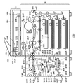
図1は、本発明の第1実施形態を示す画像形成装置(画像形成システム)を適用可能な複写装置(デジタル複合機)の構成を示す断面図である。
[First Embodiment]
FIG. 1 is a cross-sectional view showing a configuration of a copying apparatus (digital multifunction peripheral) to which the image forming apparatus (image forming system) according to the first embodiment of the present invention can be applied.
図1に示すように、本実施形態の画像形成装置(画像形成システムとも呼ぶ)1000は、リーダ部1およびプリンタ部2を有す。そして、該システム1000は、画像形成装置本体からのシートに対して、各種シート加工処理(例えば、くるみ製本処理、天糊製本処理、断裁処理、ステイプル処理、パンチ処理、シフト排紙処理等)を実行可能なシート処理装置(フィニッシャとも呼ぶ)の一例として、製本ユニット230も有す。
As shown in FIG. 1, an image forming apparatus (also referred to as an image forming system) 1000 according to this embodiment includes a
以下、リーダ部1の構成および動作について説明する。なお、プリンタ部2の構成及び製本ユニット(シート処理装置とも呼ぶ)230の構成および動作については後述する。
Hereinafter, the configuration and operation of the
尚、上記画像形成システム1000において、リーダ部1やプリンタ部2やシート処理装置230等の各種ユニットは、同一筐体内に内蔵される一体型の構成でも良いし、それぞれ、別筐体の別体型の構成でも良い。
In the
又、例えば、本実施形態のように、リーダ部1とプリンタ部2を具備する画像形成装置本体に対して、シート処理装置230のようなシート処理装置を、オプションとして、接続可能にしたシステム構成でも良い。又、例えば、画像形成装置本体自身が、標準装備として、シート処理装置230を具備した装置構成でも良い。このように本実施形態は、如何なる装置構成、システム構成であっても良い。
Further, for example, as in the present embodiment, a system configuration in which a sheet processing apparatus such as a
図1に示すリーダ部1において、101は原稿給送装置で、この原稿給送装置101上に積載された原稿束の原稿は、1枚ずつ、先頭ページから順次、原稿台ガラス面102上に搬送される。原稿が原稿台ガラス面102の所定位置へ搬送されると、スキャナ部のランプ103が点灯し、かつスキャナユニット104が移動して原稿を照射する。原稿の反射光は、ミラー105,106,107,レンズ108を介してCCDイメージセンサ部109(以下CCDと称する)に入力される。
In the
図2,図3は、図1に示したリーダ部1の信号処理構成を示す回路ブロック図である。なお、図2,図3において、図1と同一のものには同一の符号を付してある。以下、構成および動作について説明する。
2 and 3 are circuit block diagrams showing a signal processing configuration of the
図2に示すように、CCD109に照射された原稿の反射光は、ここで光電変換され、レッド(R)、グリーン(G)、ブルー(B)の各色の電気信号に変換される。そして、CCD109からのカラー情報は、次の増幅器110R,110G,110BでA/D変換器(A/D)111の入力信号レベルに合わせて増幅される。
As shown in FIG. 2, the reflected light of the original irradiated on the
次に、A/D変換器111からの出力信号は、シェーディング回路112に入力され、ここでランプ103の配光ムラや、CCD109の感度ムラが補正される。シェーディング回路112からの信号は、Y信号生成・色検出回路113に入力される。
Next, the output signal from the A /
Y信号生成・色検出回路113は、シェーディング回路112からの信号を下記の式で演算を行いY信号を得るY生成回路と、R,G,Bの信号から7つの色に分離し各色に対する信号を出力する色検出回路とを有する。
The Y signal generation /
「Y=0.3R+0.6G+0.1B」
Y信号生成・色検出回路113からの出力信号は、変倍・リピート回路114に入力される。スキャナユニット104の走査スピードにより副走査方向の変倍を、変倍・リピート回路114により主走査方向の変倍を行う。また変倍・リピート回路114により複数の同一画像を出力することが可能である。
“Y = 0.3R + 0.6G + 0.1B”
An output signal from the Y signal generation /
輪郭・エッジ強調回路115は、変倍・リピート回路114からの信号の高周波成分を強調することによりエッジ強調および輪郭情報を得る。輪郭・エッジ強調回路115からの信号は、マーカエリア判定・輪郭生成回路116とパターン化・太らせ・マスキング・トリミング回路117に入力される。
The contour /
マーカエリア判定・輪郭生成回路116は、原稿上の指定された色のマーカペンで書かれた部分を読み取りマーカの輪郭情報を生成し、次のパターン化・太らせ・マスキング・トリミング回路117へ送る。
The marker area determination /
パターン化・太らせ・マスキング・トリミング回路117では、マーカエリア判定・輪郭生成回路116で生成された輪郭情報から太らせやマスキングやトリミングを行い、またY信号生成・色検出回路113からの色検出信号によりパターン化を行い、画像データセレクタ回路118へ送る。なお、図3に示す画像処理部22は、上述した図2の110〜117に対応する。
The patterning / thickening / masking /
パターン化・太らせ・マスキング・トリミング回路117からの出力信号は、プリンタ部2に出力する場合は、後述するCPU回路部122の制御により画像データセレクタ回路118により選択され、画像データ減少回路125を介してレーザドライバ回路119に出力され、レーザドライバ回路119で前記各種処理された信号はレーザを駆動するための信号に変換される。レーザドライバ回路119の出力信号は、プリンタ部2に入力され可視像として画像形成が行われる。
When the output signal from the patterning / thickening / masking /
コネクタ121は、画像データセレクタ回路118により送られた画像データを、CPU回路部122の指示により、例えばLAN等の所定の通信媒体2001を介して、外部(例えば、ホストコンピュータや他の画像形成装置等の自装置1000とデータ通信可能な遠隔の外部装置2002a〜2002n等)に、送信したり、通信媒体2001を介して外部装置2002から受信した画像データを、画像データセレクタ回路118に出力するように構成されている。このように、コネクタ121は、外部インタフェース機能としての各種データ通信機能を有する。
The
画像メモリ120は、画像データセレクタ回路118により送られた画像データをCPU回路部122の指示により画像メモリ120の指定位置に後述する方法で、記憶及び読み出しを行い、回転処理、画像をメモリ上で合成する機能を行っている。又、画像メモリ120は、複数ページの画像データを記憶可能なハードディスク等の大容量画像メモリを有する。
The
CPU回路部122は、リーダ部1からの画像データ、及び、コネクタ121により受信したホストコンピュータや他の画像形成装置等の各種外部装置(図2の外部装置2002等)からの画像データを、上記画像メモリ120内部のハードディスクに記憶保持させるよう制御する。
The
画像メモリ120内部の該ハードディスクに格納した画像データは、ユーザからの指示に従い、適宜、該ハードディスクから読み出して、プリンタ部2や外部装置等の出力先へデータ出力させるよう、CPU回路部122により制御する。
The image data stored in the hard disk in the
本画像形成装置1000は、このようなハードディスクを有する画像メモリ120を用いて、複数のジョブを同時並行可能に処理できるようにCPU回路部122により制御される。例えば、あるジョブの画像データをハードディスクから読み出してプリンタ部2によりプリントさせている最中でも、当該プリント動作と並行して(同時に)、リーダ部1や外部装置から、その他のジョブのデータを受け付け可能にし、当該他のジョブの画像データをハードディスクに格納させる等の動作を実行可能に制御する。このように、非同期的な動作を本装置にて実行可能にしている。
The
勿論、あるジョブの画像データをリーダ部1或いは外部装置から入力し、当該入力データを、ハードディスクに記憶させるよう制御すると共に、当該データの入力動作と並行して、そのジョブの画像データをハードディスクから読み出し、プリンタ部2でプリントさせることも可能である。このように、1つのジョブの入力動作と出力動作とを同期的に実行できるようにも構成されている。
Of course, image data of a job is input from the
又、本実施形態の画像形成システム1000は、リーダ部1からのジョブデータを画像メモリ120のハードディスクを介してプリンタ部2によりプリントさせるコピー機能を有するだけではなく、コピー機能以外の他の機能も有する。例えば、コネクタ部121より受信したコンピュータ等の外部装置からのプリントジョブデータを画像メモリ120のハードディスクを介してプリンタ部2によりプリントさせるプリント機能や、画像メモリ120のハードディスクに格納保持した画像データをコネクタ121等のデータ通信ユニットを用いて、外部装置へ送信させるデータ送信機能等も有する。
The
このように、本実施形態の画像形成装置1000は、複数の機能を有するMFPタイプの装置(マルチファンクションペリフェラル)である。しかし、本実施形態は、これに限らず、例えば、プリント機能のみを有する装置、或いは、コピー機能のみを有する装置など、単一機能タイプの装置(シングルファンクションペリフェラル)でも良い。
As described above, the
CPU回路部122は、リーダ部1やプリンタ部2やコネクタ部121や画像メモリ部120やシート処理装置(製本装置)230等の各種ユニットを統括的に制御する。CPU回路部122は、後述する各フローチャートの処理を実行する為のプログラムや、後述する各種表示画面を操作部123に表示させる為の表示制御プログラム等を含む各種制御プログラム,エラー処理プログラムなどを記憶するROM124や、各種プログラムのワークエリアなどのために利用されるRAM125と各種タイマ制御部等を有する。なお、CPU回路部122のRAMに記憶された画像データを、CPU回路部122の指示により画像メモリ120上に展開することも可能である。
The
CPU回路部122は、このように画像形成装置1000の制御部として機能する。そして、本画像形成装置1000にて処理対象となる各種ジョブを、ユーザからの指示に応じた所望の処理形態で、各ユニットにより処理させるように制御する。
The
又、CPU回路部122は、このようなジョブ制御を司るだけでなく、ユーザインタフェースユニットの一例に相当する、表示部4−250を有する操作部123に対する表示制御等も司る。
Further, the
排紙トレイ上に積載された記録紙のサイズ,種類、束シフト済みか否かの情報は排紙トレイ毎にRAM125に記憶され、CPU回路部122は、ROM124に格納されている比較プログラムをRAM125上にロードして実行することにより、排紙トレイ毎に排紙トレイ上に積載された記録紙のサイズ,種類等を判断することができる。
Information on the size, type, and bundle shift of the recording paper loaded on the paper discharge tray is stored in the
図3に示す130はキャラクタデータROMで、キャラクタ画像が収納されているROMである。このキャラクタデータROM130は、キャラクタ画像データが格納されている。CPU回路部122は、印字するキャラクタコードからキャラクタデータROM130に格納されている画像データを読み出し、画像メモリ120上にビットマップ画像データとして展開する。また、RAM125に記憶された画像データを、CPU回路部122の指示により画像メモリ120上に展開することも可能である。
A character data ROM 130 shown in FIG. 3 is a ROM that stores character images. The character data ROM 130 stores character image data. The
操作部123は、リーダ部1の画像処理に対する画像編集内容の設定や、コピー枚数(印刷部数)の設定等の画像動作を指示する各種キー群と、操作時の内容を表示する表示部等を有している。
The
CPU回路部122は、ユーザインタフェースユニットの一例である、操作部123の表示部4−250に、各種設定画面を、表示させるよう制御する。そして、表示部4−250に表示させる各種設定画面を介して、コピー枚数(印刷部数)の設定や、出力用紙の設定(用紙サイズの設定や用紙タイプの設定)や、変倍率の設定や、片面印刷するか両面印刷するかを決定する為の印刷面の設定を、ユーザにより実行可能にする。
The
更に、CPU回路部122は、表示部4−250に表示させる各種設定画面を介して、2in1モード(シートの同一面上に2ページ分の画像データを配列形成するレイアウトモード)や4in1(シートの同一面上に4ページ分の画像データを配列形成するレイアウトモード)や8in1(シートの同一面上に8ページ分の画像データを配列形成するレイアウトモード)等の縮小レイアウトモード等、各種応用モードの設定を、ユーザにより実行可能にする。
Furthermore, the
又、CPU回路部122は、シート処理装置(製本装置230)にて実行可能な各種シート処理(くるみ製本処理、天糊製本処理、断裁処理、ステイプル処理、パンチ処理、シフト排紙処理等)のうちの、ユーザにより所望のシート処理を、プリンタ部2からのシートに対して実行させる為の設定指示も、操作部123の表示部4−250に表示させる設定画面を介して、ユーザにより実行可能に構成している。
The
このように、CPU回路部122は、ユーザインタフェースユニットとして機能する操作部123及び表示部4−250を介して、処理対象となるジョブの各種処理条件をユーザから受付可能に構成する。
As described above, the
このユーザから受け付けた各種処理条件に基づいて、CPU回路部122は、後述するような、各種の制御を実行する。後述する各種設定画面は、CPU回路部122が、表示部4−250に対して表示制御を実行することで、表示部4−250に表示される。
Based on the various processing conditions received from the user, the
CPU回路部122は、上記のようなユーザインタフェースを介して受け付けたユーザからの指示に応じた処理を、処理対象となるジョブのデータに対して実行するよう、各ユニット(リーダ部1、プリンタ部2、シート処理装置230、画像メモリ120等の本画像形成システムが具備する各種ユニット)を、制御する。
The
以下、図4〜図7を参照して、図2,図3に示した操作部123の詳細構成および操作部123による操作手順の一例について説明する。
Hereinafter, an example of a detailed configuration of the
図4は、図3に示した操作部123の詳細構成を示す平面図である。
FIG. 4 is a plan view showing a detailed configuration of the
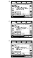
図5は、図4に示した液晶表示部4−250に表示される操作画面の一例を示す模式図である。 FIG. 5 is a schematic diagram illustrating an example of an operation screen displayed on the liquid crystal display unit 4-250 illustrated in FIG.
図4に示すように、操作部123には、各種キー(ハードキー群4−240)と、液晶表示装置からなるドットマトリックスで構成される液晶表示部4−250とが配置されている。液晶表示部4−250は表面にタッチパネルを備えており、キー表示部を押下することによりキー入力が可能となる。ハードキー群4−240は、各種ハードキー4−241〜4−248を有する。
As shown in FIG. 4, the
キー4−243は電源キーで、電源のON/OFFをする為のキーである。キー4−244は節電キーで、節電モードにする/節電モードを解除する為のキーである。キー4−241はスタートキーで、原稿読取開始指示や、印刷開始指示等、各種処理をスタートすさせる指示をユーザにより入力する為のキーである。キー4−242はストップキーで、本装置により実行中のジョブ処理を中止させる指示をユーザにより入力する為のキーである。 A key 4-243 is a power key for turning the power ON / OFF. A key 4-244 is a power saving key, and is a key for setting the power saving mode / releasing the power saving mode. A key 4-241 is a start key for inputting an instruction to start various processes such as a document reading start instruction and a print start instruction by the user. A key 4-242 is a stop key, and is a key for the user to input an instruction to stop the job processing being executed by the apparatus.
また、キー群4−245は、コピー枚数、ズーム倍率等を入力させる0〜9までのテンキーとその入力をクリアするためのクリアキーを有する。このキー郡4−245で入力されたコピー部数は、液晶表示部4−253に表示される。 The key group 4-245 has ten keys from 0 to 9 for inputting the number of copies, zoom magnification, and the like, and a clear key for clearing the input. The number of copies input in the key group 4-245 is displayed on the liquid crystal display unit 4-253.
キー4−246は復帰キーで、設定モードを標準状態に復帰するためのキーである。キー4−247はガイドキーで、各機能のガイド画面を表示させるためのキーである。キー4−248はユーザモードキーで、機器の各種設定を行うためのキーである。 A key 4-246 is a return key for returning the setting mode to the standard state. A key 4-247 is a guide key for displaying a guide screen for each function. A key 4-248 is a user mode key for performing various settings of the device.
液晶表示部4−250には、CPU回路部122からの制御により、装置の状態、コピー枚数、倍率、選択用紙及び各種操作画面を表示する。液晶表示部4−250には、タッチキーも表示される。
The liquid crystal display unit 4-250 displays the state of the apparatus, the number of copies, the magnification, the selected paper, and various operation screens under the control of the
液晶表示部4−250において、キー4−252は、給紙段及びオート用紙を選択するキーであり、このキーがユーザにより押下されると、これに応答し、CPU回路部122は、液晶表示部4−250に図5(a)に示す用紙選択画面を表示するよう操作部123を制御する。
In the liquid crystal display unit 4-250, a key 4-252 is a key for selecting a paper feed stage and auto paper. When this key is pressed by the user, the
図5(a)に示す用紙選択画面のキー群4−271で給紙段が選択され、閉じるキー4−270がユーザにより押下されると、これに応答し、CPU回路部122は、この画面は閉じて図4の画面に戻し、選択された給紙段を表示部4−251に表示するよう操作部123を制御する。
When the paper feed stage is selected by the key group 4-271 on the paper selection screen shown in FIG. 5A and the close key 4-270 is pressed by the user, the
図4のキー4−258,キー4−262は、濃度調整を行うためのキーで、これらのキーにより調整される濃度を、CPU回路部122が表示部4−263に表示させる。キー4−259は、自動濃度調整機能をON/OFFするためのキーである。キー4−261は写真モード/テキストモード等の設定を行うためのキーである。
Keys 4-258 and 4-262 in FIG. 4 are used for density adjustment. The
キー4−254,キー4−255は、それぞれ等倍,縮小/拡大を設定するためのキーである。キー4−255が押下されると、CPU回路部122は液晶表示部4−250に、図5(b)に示す倍率画面を表示させ、拡大縮小を詳細に設定可能にするよう操作部123を制御する。図5(b)に示す倍率画面のキー群4−273で倍率が選択され、閉じるキー4−272がユーザにより押下されると、これに応答し、CPU回路部122はこの画面は閉じて図4の画面に戻し、設定された倍率を表示部4−251に表示させる。
Keys 4-254 and 4-255 are keys for setting equal magnification and reduction / enlargement, respectively. When the key 4-255 is pressed, the
キー4−257は両面キーで、キー4−257が押下されると、CPU回路部122は液晶表示部4−250に、図5(c)に示す両面印刷設定画面を表示させる。以下、両面印刷の設定に関して図5(c)を参照して説明する。
A key 4-257 is a double-sided key. When the key 4-257 is pressed, the
図5(c)において、キー4−280は、原稿片面を両面印刷するための設定キーであり、キー4−281は、両面原稿から両面印刷するための設定キーである。キー4−283は、両面原稿を片面印刷するための設定キーであり、キー4−284は、ページ連写両面を行うための設定キーである。 In FIG. 5C, a key 4-280 is a setting key for duplex printing on one side of a document, and a key 4-281 is a setting key for duplex printing from a duplex document. A key 4-283 is a setting key for single-sided printing of a double-sided document, and a key 4-284 is a setting key for performing page continuous double-sided copying.
キー4−285は、図5(c)の両面印刷設定画面においてユーザによりなされた操作設定を有効にするためのキーであり、このキーが押下されると、CPU回路部122は、図5(c)の両面印刷設定画面での操作設定を有効にし、液晶表示部4−250の表示を図4の画面に戻す。また、キー4−282は、図5(c)において行った操作設定を取り消すためのキーであり、このキーが押下されると、CPU回路部122は図5(c)の両面印刷設定画面での操作設定を無効にし、液晶表示部4−250の表示を図4の画面に戻す。
A key 4-285 is a key for validating operation settings made by the user on the duplex printing setting screen of FIG. 5C. When this key is pressed, the
キー4−286は、詳細設定をユーザにより実行可能にする為のキーであり、このキー4−286がユーザにより押下されると、これに応答し、CPU回路部122は、液晶表示部4−250に、図5(d)に示す両面印刷詳細設定画面を表示させる。以下、両面印刷の詳細設定に関して図5(d)を参照して説明する。
A key 4-286 is a key for enabling detailed setting by the user. When the key 4-286 is pressed by the user, the
図5(d)において、キー4−290は、両面印刷物を左右開きに印刷するための設定キーであり、キー4−291は、両面印刷物を上下開きに印刷するための設定キーである。キー4−291又はキー4−292により両面印刷の種類を選択し、閉じるキー4−292が押下されると、CPU回路部122はこの画面は閉じ、液晶表示部4−250の表示を図5(c)の画面に戻す。
In FIG. 5D, a key 4-290 is a setting key for printing a double-sided printed material in a left-right direction, and a key 4-291 is a setting key for printing a double-sided printed material in a vertical direction. When the type of double-sided printing is selected using the key 4-291 or the key 4-292 and the close key 4-292 is pressed, the
以上示したように、図5(c)の両面印刷設定画面,図5(d)の両面印刷詳細設定画面により、両面印刷が設定可能となる。 As described above, duplex printing can be set by the duplex printing setting screen in FIG. 5C and the duplex printing detailed setting screen in FIG.
図4の表示画面上のキー4−256は、シート処理装置230により実行させるべきシート処理をユーザが指示する為の設定画面を操作部123の表示部に表示させる指示をユーザにより入力可能にする為のソータキーである。
A key 4-256 on the display screen in FIG. 4 enables the user to input an instruction to display a setting screen for the user to instruct the sheet processing to be executed by the
キー4−256がユーザにより押下されると、これに応答し、CPU回路部122は、操作部123の液晶表示部4−250の表示を、例えば、後述する図19に示すシート処理設定画面1900に移行させる。そして、当該設定画面1900を表示部4−250に表示させることで、シート処理装置230により実行可能なシート処理の候補(ステイプル処理、パンチ処理、断裁処理、くるみ製本処理、天糊製本処理、シフト排紙処理等のシート処理に関わる選択候補)をユーザに提示するようCPU回路部122により制御する。
When the user presses the key 4-256, in response to this, the
CPU回路部122は、図19のようなシート処理設定画面を介して、所望のシート処理の実行指示を、ユーザから受け付け可能にする。そして、当該シート処理設定画面を介してユーザにより指示に応じたシート処理を、プリンタ部2からの処理対象のジョブのシートに対して、実行するように、CPU回路部122により、シート処理装置230を制御する。
The
キー4−260は応用モードキーであり、キー4−260がユーザにより押下されると、これに応答し、CPU回路部122は、液晶表示部4−250の表示を、図6(a)に示す応用モード設定画面に移行し、各種応用モードの設定を可能とするよう制御する。
A key 4-260 is an application mode key. When the user presses the key 4-260, the
以下、図6,図7を参照して、本実施形態の画像形成装置における製本設定手順の流れについて説明する。 Hereinafter, the flow of the bookbinding setting procedure in the image forming apparatus according to the present embodiment will be described with reference to FIGS.
図6,図7は、CPU回路部122が、図4に示したユーザインタフェースユニットの一例としての操作部123の液晶表示部4−250に表示させるように制御する操作画面の一例を示す模式図である。
6 and 7 are schematic diagrams illustrating an example of an operation screen that the
図6(a)は、図4に示す操作画面上のキー4−260がユーザにより押下されたことに応じて、CPU回路部122が表示部4−250に表示させる応用モード画面である。
FIG. 6A shows an application mode screen that the
図6(a)の画面上のキー801は、製本モード(くるみ製本や、天糊製本など、糊付け製本処理モードを含む)を設定するための表示キー(ソフトキー)である。キー801がユーザにより押下されると、これを受け、CPU回路部122は、表示部4−250に、図6(b)に示す原稿サイズ選択画面を表示させる。
A key 801 on the screen of FIG. 6A is a display key (soft key) for setting a bookbinding mode (including glue binding and bookbinding processing modes such as case binding and top binding). When the user presses the key 801, the
図6(a)の画面上のキー811は連続読込キーである。キー811がユーザにより押下された場合には、原稿給送装置101上に一度に載置できる量を超える大量の原稿であっても、複数回に分けて原稿を載置して一連の原稿として読み込み処理する継ぎ足し読み込み処理を行うことできるように、CPU回路部122は、操作部123及びリーダ部1及び画像メモリ部120並びにプリンタ部2等を制御する。
A key 811 on the screen of FIG. 6A is a continuous reading key. When the key 811 is pressed by the user, a large number of documents exceeding the amount that can be placed on the
図6(b)は、上記製本モードにおいて処理対象となるジョブの原稿サイズを指定するための操作画面である。図6(b)の画面上のキー群802は、上記製本モードにおいて処理対象となるジョブの原稿サイズとしてユーザにより指定可能なサイズをユーザにより設定させる為の原稿サイズ指定キーである。例えば、ユーザにより、図6(b)の画面上の「A4」サイズが押下され「次へ」キーが押下されると、CPU回路部122は、液晶表示部4−250に図6(c)に示す操作画面を表示させる。
FIG. 6B is an operation screen for designating the document size of a job to be processed in the bookbinding mode. A
図6(c)は、製本の種類を指定するための操作画面である。図6(c)の設定画面上の糊付け製本キー803をユーザが押下することで、ユーザは、糊付け製本処理(後述する、くるみ製本処理,天糊製本処理)を指定することが出来る。一方、図6(c)の設定画面上の中綴じ製本キー804をユーザが押下することで、ユーザは、中綴じ製本を指定することが出来る。
FIG. 6C shows an operation screen for designating the type of bookbinding. When the user presses the
図6(c)の設定画面を介して、糊付け製本処理、或いは、中綴じ製本処理の、何れかのシート処理の設定がユーザにより実行された事に応答し、CPU回路部122は、処理対象のジョブの処理条件として、当該シート処理の設定を反映させる。このように、ユーザから受け付けた指示に応じた一連のジョブ処理条件は、後述する各種の制御(ジョブ処理制御や表示制御等)に用いられる。
The
CPU回路部122は、このような、操作部123や表示部4−250等のユーザインタフェースユニットを介して処理対象となるジョブに対してユーザからの指示に基づいて設定された各種ジョブ処理条件に基づいて、後述する各種制御を実行するよう、本画像形成システム1000を制御する。例えば、本実施形態の画像形成システム1000にて実行可能な糊付け製本処理に特化して説明すると、次のような、制御を行う。
The
本実施形態の画像形成システムのCPU回路部122は、処理対象のジョブに対して上述のようなユーザインタフェースを介してユーザにより設定された当該ジョブの処理条件が、所定の条件を満足するか否かを判断する。そして、その判断結果に基づいて、糊付け製本処理の実行可否を制御する。
The
例えば、処理対象のジョブが、所定の条件を満足するジョブである場合には、当該ジョブのシートに対してシート処理装置230により糊付け処理を実行する事を許可するよう制御する。一方、処理対象のジョブが、所定の条件を満足しないジョブである場合には、シート処理装置230による当該ジョブのシートに対する糊付け処理の実行を禁止するよう制御する。
For example, when the job to be processed is a job that satisfies a predetermined condition, control is performed to allow the
又、本実施形態では、シート処理装置230が、プリンタ部2から給送される処理対象のジョブのシートに対して実行可能な糊付け処理は、2種類存在する。例えば、本実施形態の画像形成システム1000は、一例として、くるみ製本モードと天糊製本モードの2種類のシート糊付け処理モードを具備する(この2種類の糊付け処理については後述する)。
In the present embodiment, there are two types of gluing processes that the
CPU回路部122は、上述の2種類の糊付け処理モードのうちのユーザからの指示により選択された糊付け処理モードを実行させるようシート処理装置230を制御する。
The
このように本実施形態の画像形成システムは、複数種類の糊付け処理モードを具備し、処理対象のジョブ毎に、選択的に、これらの糊付け処理を、実行可能に構成されている。 As described above, the image forming system according to the present embodiment includes a plurality of types of gluing processing modes, and is configured to selectively execute these gluing processes for each job to be processed.
このような構成を前提とし、本実施形態では、ユーザにより処理条件の設定がなされた処理すべきジョブが所定の条件を満足するジョブであるか否かを、CPU回路部122等が主体となり、確認するよう構成されている。そして、上記判断結果に基づいて、上述のような複数種類の糊付け処理を含む、シート糊付け処理に関係する(影響する)、各種の所定の処理の実行可否を、CPU回路部122等が主体となり、制御している。
Based on such a configuration, in this embodiment, the
例えば、「処理対象のジョブは、第1の所定条件を満たすジョブである」とCPU回路部122により判断したとする。この場合に、CPU回路部122は、くるみ製本モードおよび天糊製本モードを選択的(択一的)に実行することを許可する。即ち、くるみ製本モードおよび天糊製本モードのうちの、ユーザが望む糊付け処理モードを任意に選択可能に制御する。
For example, it is assumed that the
但し、この制御を行う場合でも、これらのモードをユーザが選択する場合には、二者択一となるよう制御する。即ち、これら2つの糊付け処理モードのうち、ユーザが所望の糊付け処理モードを、1つのみ選択する事を許可する。換言すると、CPU回路部122は、処理すべき1つのジョブに対して、くるみ製本モードと天糊製本モードの両方を同時に設定することを禁止する。
However, even when this control is performed, when these modes are selected by the user, control is performed so as to be an alternative. That is, the user is allowed to select only one desired gluing processing mode from these two gluing processing modes. In other words, the
これにより、例えば、くるみ製本モードを希望するユーザは、適正な、くるみ製本処理が施された、ユーザの所望の出力結果を提供できる。他方、天糊製本モードを希望するユーザには、適正な、天糊製本処理が施された、ユーザの所望の出力結果を、提供することが出来る。 Thereby, for example, a user who desires the case binding mode can provide a user's desired output result that has been subjected to a proper case binding process. On the other hand, it is possible to provide the user who desires the top-sheet binding mode with the user's desired output result that has been subjected to an appropriate top-sheet binding process.
本実施形態の画像形成システム1000は、このような、様々なユーザからの様々な製本処理ニーズに柔軟に対応する事が出来るという効果を奏する事が出来る。
The
しかも、例えば、この効果を、従来技術等で想定したような各種の問題等が、本画像形成システム1000にて発生することを抑えて、得ることが出来る、という効果についても、上記効果に加えて得ることが可能になる。
Moreover, for example, this effect can be obtained by suppressing the occurrence of various problems as assumed in the prior art etc. in the
又、上述のケースとは異なる判断をCPU回路部122が行ったとする。例えば、「処理対象のジョブは、第1の所定条件を満たすジョブではないが、第2の所定条件を満たすジョブである」に該当する判断結果を、CPU回路部122により下したとする。このケースの場合、CPU回路部122は、くるみ製本モードおよび天糊製本モードの2種類の糊付け処理モードのうちの、何れか一方の糊付け処理モードのみ、選択実行する事を許可する。他方の糊付け処理モードについては、ユーザにより選択すること自体も禁止するように制御する(他方の糊付け処理モードについては選択不可能となるように制御する)。
Further, it is assumed that the
例えば、この制御では、ユーザインタフェースユニット(ここで言う、ユーザインタフェースユニットとは、リーダ部1からのジョブを処理する場合ならば操作部123がこれに該当する。ホストコンピュータ等の外部装置からのジョブならば外部装置の操作部がこれに相当する)を介して、天糊製本モードをユーザにより選択することは、許可するよう、CPU回路部122等が主体となり、制御する。しかし、CPU回路部122は、くるみ製本モードの選択実行をユーザが該ユーザインタフェースユニットを介して指示することは禁止するよう制御する。
For example, in this control, the user interface unit (here, the user interface unit corresponds to the
これにより、例えば、処理対象のジョブが、くるみ製本モードに適さないジョブであるにも拘らず、ユーザが間違って、くるみ製本モードを設定してしまう等の、ユーザによる誤操作の発生を、未然に防止できる。又、例えば、このような不適正な設定をユーザが行った事が原因で、本画像形成システムにて誤動作やトラブル等が発生する事を未然に防止できる。尚且つ、例えば、ユーザが所望とする出力結果とは異なる出力結果を作成してしまう等の無駄を排除することが出来る。 As a result, for example, the occurrence of an erroneous operation by the user, such as the user accidentally setting the case binding mode, even though the job to be processed is a job that is not suitable for the case binding mode, Can be prevented. Further, for example, it is possible to prevent malfunctions and troubles from occurring in the image forming system due to the user performing such inappropriate settings. In addition, for example, it is possible to eliminate waste such as creating an output result different from the output result desired by the user.
但し、この制御を実行する場合(くるみ製本モード禁止、天糊製本モードのみ許可する場合)であっても、例えば、CPU回路部122は、当該ジョブのユーザからの指示次第で、くるみ製本処理モードの実行は禁止した状態で、当該処理対象のジョブのプリント動作の実行は許可するよう、操作部123やプリンタ部2やシート処理装置230を、制御する。
However, even when this control is executed (case binding mode is prohibited, only the case binding mode is permitted), for example, the
尚且つ、当該ジョブのユーザからの指示次第で、くるみ製本モードから天糊製本モードに、ジョブ処理条件を、設定変更できるように、操作部123やプリンタ部2やシート処理装置230を制御する。
In addition, depending on an instruction from the user of the job, the
このような構成により、例えば、ある程度の制限があっても、極力、本画像形成システムに柔軟性を持たせることができる。又、例えば、ユーザの利便性、装置の利用効率等も向上させる事が出来る。 With such a configuration, for example, even if there are some restrictions, the present image forming system can be made as flexible as possible. In addition, for example, user convenience, device utilization efficiency, and the like can be improved.
又、更に上述のケースに該当しない判断をCPU回路部122が行ったとする。例えば、「処理対象のジョブは、第1の所定条件を満たすジョブではなく、且つ、第2の所定条件を満たすジョブでもない」に該当する判断結果を、CPU回路部122により、行ったとする。このケースの場合、CPU回路部122は、くるみ製本モードを選択実行することを禁止する。且つ、天糊製本モードを選択実行する事も禁止する。このように、2種類の糊付け処理モードの両方とも禁止する。
Further, it is assumed that the
これにより、例えば、処理対象のジョブが、くるみ製本モードにも適さず、天糊製本モードにも、適さないジョブであるにも拘らず、ユーザが間違って、くるみ製本モードや天糊製本モードを設定してしまう等の、ユーザによる誤操作の発生を、未然に防止できる。又は、例えば、このような不適正な設定をユーザが行った事が原因で、本画像形成システムにて誤動作やトラブル等が発生する事を未然に防止できる。尚且つ、例えば、ユーザが所望とする出力結果とは異なる出力結果を作成してしまう等の無駄を排除することが出来る。 As a result, for example, even if the job to be processed is not suitable for the case binding mode and is not suitable for the case binding mode or the case binding mode, the user mistakenly changes the case binding mode or the case binding mode. It is possible to prevent an erroneous operation by the user such as setting. Or, for example, it is possible to prevent a malfunction or a trouble from occurring in the image forming system due to the user performing such an inappropriate setting. In addition, for example, it is possible to eliminate waste such as creating an output result different from the output result desired by the user.
但し、この制御を実行する場合(くるみ製本モード、天糊製本モードの両方とも選択実行禁止する場合)であっても、CPU回路部122は、例えば、当該ジョブのユーザからの指示次第で、くるみ製本処理モードおよび天糊製本モードの両モード共に実行を禁止した状態で、当該処理対象のジョブのプリント動作の実行自体は、許可するよう、操作部123やプリンタ部2やシート処理装置を、制御する。なお、この際、CPU回路部122が、プリント動作の実行自体を行うかどうかを操作部123を解してユーザに問い合わせ、ユーザからの返答指示に応じてプリント動作のみを実行するかどうかを制御するように構成してもよい。また、予めユーザモード等に「くるみ製本処理モードおよび天糊製本モードの両モード共に実行を禁止した状態でのプリント動作の実行の有無」を設定しておき、該設定に応じて、CPU回路部122が、上記状態でのプリント動作の実行の有無を制御するように構成してもよい。
However, even when this control is executed (when both the case binding mode and the top binding mode are prohibited), the
これにより、例えば、本画像形成システム1000の柔軟性や利用効率、ユーザの利便性を更に一層向上させる事が出来る。
Thereby, for example, the flexibility and utilization efficiency of the
尚、上述のように、CPU回路部122は、処理対象のジョブが所定の条件を満たすか否かを判定する。このような判断を行う際に、CPU回路部122は、処理対象のジョブに含まれる印刷データの総ページ数情報や、そのジョブに対してユーザにより設定された各種印刷条件情報等、処理対象のジョブに関係する情報(ジョブ属性情報)を用いる。又、後述する各種ルールを定義した管理情報(例えば、後述する図18や図20図37や図38等の各種管理テーブルに記述された管理情報等)も用いる。そして、該ジョブ属性情報と管理情報との比較判定処理等を行う。
As described above, the
又、上記3つのケースのうちの、2番目のケースや3番目のケースにおいて、くるみ製本モードや天糊製本モードが禁止対象のシート処理に該当する。しかし、本実施形態のシート処理装置230は、このような糊付け処理以外の種類のシート処理(ステイプル、パンチ、中綴じ製本、断裁、シフト排紙等)を実行することが出来る。
In the second case and the third case among the above three cases, the case binding mode and the top binding mode correspond to the sheet processing to be prohibited. However, the
そこで、本実施形態において、例えば、上述の二種類の糊付け処理を含むシート糊付け処理の実行を禁止した場合でも、他の種類のシート処理の選択実行を、ユーザにより設定された上記ジョブ処理条件に基づいて、許可するようにCPU回路部122により制御する。
Therefore, in the present embodiment, for example, even when the execution of the sheet gluing process including the above-described two types of gluing processes is prohibited, the selection and execution of other types of sheet processes are set to the job processing conditions set by the user. Based on this, control is performed by the
このように構成することで、本画像形成システム1000の利用効率や柔軟性等、上記効果を更に一層向上させる事が可能になる。
With this configuration, it is possible to further improve the above-described effects such as utilization efficiency and flexibility of the
又、上述の「処理対象のジョブが所定の処理条件のジョブか否かの判断処理」として、例えば、以下のような処理を、CPU回路部122により行う。
In addition, as the above-described “determination process for determining whether a job to be processed is a job with a predetermined processing condition”, for example, the
(例1)CPU回路部122は、ユーザにより各種出力処理条件が設定された処理すべきジョブにて使用されるシートの総枚数が、第1の所定枚数を超えるか否かを確認する為の判定処理(以下、第1の判定処理とも呼ぶ)を実行する。この判定結果に応じて、当該ジョブのシートに対する糊付け処理の実行可否を決定する。
(Example 1) The
例えば、上記判定処理を実行した結果、処理対象のジョブが、上記第1の所定枚数を超える数のシートを利用するジョブである場合には、CPU回路部122は、処理対象のジョブのシートに対して、くるみ製本処理を実行する事を禁止し、且つ、天糊製本処理を実行する事も禁止する。即ち、このケースに該当する場合、CPU回路部122は、2種類のシート糊付け処理モードの両方とも実行を禁ずる。
For example, if the job to be processed is a job that uses more than the first predetermined number of sheets as a result of executing the determination process, the
(例2)本実施形態では、第1の所定枚数以外の閾値として、第2の所定枚数なるものを、用いている。尚且つ、第2の所定枚数は、第1の所定枚数よりも、少ない枚数である。例えば、第1の所定枚数を150枚とし、第2の所定枚数を10枚とする。 (Example 2) In the present embodiment, the threshold value other than the first predetermined number is the second predetermined number. In addition, the second predetermined number is smaller than the first predetermined number. For example, the first predetermined number is 150 and the second predetermined number is 10.
このような構成のもとで、CPU回路部122は、ユーザにより各種出力処理条件が設定された処理すべきジョブにて利用されるシートの総枚数が、第2の所定枚数未満であるか否かを確認する為の判定処理(以下、第2の判定処理とも呼ぶ)を実行する。この判定結果に応じて、当該ジョブのシートに対する糊付け処理の実行可否を決定する。
Under such a configuration, the
例えば、上記判定処理を実行した結果、処理対象のジョブが、上記第2の所定枚数未満のシートしか本画像形成装置にて利用しないジョブ(例えば、記録紙10枚未満のジョブ等)である場合には、CPU回路部122は、処理対象のジョブのシートに対して、くるみ製本処理を実行する事を禁止する。
For example, as a result of executing the determination process, the job to be processed is a job that uses only less than the second predetermined number of sheets in the image forming apparatus (for example, a job of less than 10 recording sheets). In this case, the
尚、本実施形態では、上記(例2)の第2の判定処理は、処理すべきジョブが、ユーザにより「くるみ製本処理モード」が選択されたジョブに相当する場合において、実行される。CPU回路部122は、上記第2の判定処理を含む、当該(例2)に示すような一連の制御シーケンスを、くるみ製本モードが選択されたジョブを処理する場合において、実行する。
In the present embodiment, the second determination process of (Example 2) is executed when the job to be processed corresponds to the job for which the “case binding processing mode” is selected by the user. The
一方、処理すべきジョブが、「天糊製本処理モード」が選択されたジョブである場合には、上記第2の判定処理の実行を禁ずる。CPU回路部122は、天糊製本モードが選択されたジョブを処理する場合には、上記第2の判定処理を含む、当該(例2)の一連の制御シーケンスを実行する事自体を禁止する。
On the other hand, when the job to be processed is a job for which the “sheet binding process mode” is selected, the execution of the second determination process is prohibited. When processing a job for which the top binding mode has been selected, the
但し、上述の(例1)における第1の判定処理を含む一連の制御シーケンスは、くるみ製本処理モードが選択されたジョブを処理する場合でも、天糊製本モードが選択せれたジョブを処理する場合でも、両ケース共に、実行するように制御する。 However, the series of control sequences including the first determination process in (Example 1) described above is for processing a job for which the case binding mode is selected, even when processing a job for which the case binding mode is selected. However, both cases are controlled to be executed.
以上の構成を前提として、更に、以下の(例3)や(例4)に示すような制御を、CPU回路部122により実行する。
On the premise of the above configuration, the
(例3)くるみ製本モードが選択されたジョブを処理する場合において、処理すべきジョブが、「上記第1所定枚数以下のシートを利用するジョブに該当し、尚且つ、第2の所定枚数未満のシートしか利用しないジョブには該当しない」と、判断した場合(即ち、第2の所定枚数≦処理すべきジョブにて使用すべきシートの合計枚数≦第1の所定枚数)、CPU回路部122は、当該ジョブのシートに対して、くるみ製本処理を実行する事を許可する。
(Example 3) When processing a job for which the case binding mode is selected, the job to be processed corresponds to “a job using the first predetermined number of sheets or less and less than the second predetermined number of sheets”. When the
(例4)天糊製本モードが選択されたジョブを処理する場合において、CPU回路部は、処理すべきジョブが、「上記第1所定枚数以下のシートを利用するジョブに該当する」と、判断した場合には、そのジョブにて必要なシートの合計枚数が上記第2の所定枚数未満であるか否かに関係なく、当該ジョブのシートに対して、天糊製本処理を実行する事を許可する。 (Example 4) In the case of processing a job for which the sheet binding mode is selected, the CPU circuit unit determines that the job to be processed corresponds to “a job using the first predetermined number of sheets or less”. If the total number of sheets required for the job is less than the second predetermined number, it is permitted to execute the book binding process on the sheets of the job. To do.
尚、(例1)〜(例4)の説明を、先に説明した例と照らし合わせて説明すると、以下のとおりである。 In addition, it is as follows when description of (Example 1)-(Example 4) is demonstrated in light of the example demonstrated previously.
上記の「第1の所定条件を満たすジョブ」の例としては、「上記第1の所定枚数以下の出力枚数を必要とし、且つ、上記第2の所定枚数以上の出力枚数を必要とするジョブ」が、これに該当する。このケースの場合、くるみ製本モードの実行を許可する。天糊製本モードの実行も許可する。但し、ユーザにより何れか一方のみを選択許可する。即ち、同時に、2種類のシート糊付け処理を選択する事は禁ずる。 As an example of the above-mentioned “job satisfying the first predetermined number”, “a job that requires an output number equal to or smaller than the first predetermined number and requires an output number equal to or larger than the second predetermined number” This is the case. In this case, execution of the case binding mode is permitted. Execution of the book binding mode is also permitted. However, only one of them is allowed to be selected by the user. That is, it is prohibited to select two types of sheet gluing processes at the same time.
上記の「第1の所定条件を満たすジョブではないが、第2の所定条件を満たすジョブ」の例としては、「上記第1の所定枚数未満の枚数を必要とし、且つ、上記第2の所定枚数以下の出力枚数を必要とするジョブ」が、これに該当する。このケースの場合、くるみ製本モードの実行を禁止する。但し、天糊製本モードの実行は許可する。 As an example of the above-mentioned “job not satisfying the first predetermined condition but satisfying the second predetermined condition”, “the number of sheets less than the first predetermined number is required and the second predetermined number is satisfied” This corresponds to “a job that requires an output number equal to or less than the number”. In this case, execution of the case binding mode is prohibited. However, the execution of the top glue binding mode is permitted.
上記の「第1の所定条件を満たすジョブでもなく、且つ、第2の所定条件を満たすジョブでもないジョブ」の例としては、「上記第1の所定枚数を超える数の出力枚数を必要とするジョブ」が、これに該当する。このケースの場合には、くるみ製本モードの実行を禁ずる。且つ、天糊製本モードの実行も禁ずる。 As an example of the above-mentioned “job not satisfying the first predetermined condition and not satisfying the second predetermined condition”, “the number of output sheets exceeding the first predetermined number is required” “Job” corresponds to this. In this case, execution of the case binding mode is prohibited. In addition, execution of the top glue binding mode is also prohibited.
以上のような関係になる。尚、何故このような制御を取り入れるかは、後で説明するが、本画像形成システムにおける主な特徴の1つである。 The relationship is as described above. The reason why such control is adopted is one of the main features of the image forming system, which will be described later.
このように、本実施形態の画像形成システム1000では、処理すべきジョブが、所定の条件を満足するか否に応じて、シート処理装置230により実行可能な糊付け処理に関係する所定の処理の実行可否(上述の例では、各種シート糊付け処理自体の実行可否)を、CPU回路部122が主体となり、制御する。
As described above, in the
尚、CPU回路部122が、上述のような判定処理(即ち、処理対象のジョブが所定の条件を満たすか否かの判定処理)を行うにあたり、例えば、以下のような判断材料を、CPU回路部122は利用している。
When the
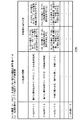
例えば、上述のような「処理すべきジョブの出力枚数の合計に関わる処理条件データ」である。CPU回路部122は、このユーザ設定に基づいた情報を、後述する、図37に示す管理テーブル3700、或いは、図38に示す管理テーブル3800の、機能制限管理テーブルの管理情報と、比較する。
For example, “processing condition data relating to the total number of output jobs to be processed” as described above. The
その他にも、「処理すべきジョブの出力用紙自体に関わる処理条件データ」等も存在する。例えば、ユーザにより処理対象のジョブにて設定された、プリントすべきシートのサイズ情報に関する処理条件や、プリントすべきシートの種類に関する処理条件等が、これに該当する。CPU回路部122は、このユーザ設定に基づいた情報を、図18に示す管理テーブル1800の管理情報と比較する。
In addition, “processing condition data relating to the output sheet of the job to be processed” exists. For example, the processing condition regarding the size information of the sheet to be printed, the processing condition regarding the type of the sheet to be printed, and the like set by the job to be processed by the user correspond to this. The
又、「処理すべきジョブに対してユーザにより選択されたシート処理の種類に関わる処理条件データ」等も存在する。例えば、ユーザにより設定されたシート処理の種類が、シート処理装置230にて実行可能な複数種類シート処理(例えば、ステイプル処理、パンチ処理、断裁処理、シフト排紙処理、くるみ製本処理、天糊製本処理、中綴じ製本処理等の各種シート処理)のうちのユーザにより設定されたシート処理モードに関わる処理条件データ」等も存在する。CPU回路部122は、このユーザ設定に基づいた情報を、図20に示す管理テーブル1800の管理情報と、比較する。
There is also “processing condition data relating to the type of sheet processing selected by the user for the job to be processed”. For example, the types of sheet processing set by the user are a plurality of types of sheet processing that can be executed by the sheet processing apparatus 230 (for example, stapling processing, punching processing, cutting processing, shift paper discharge processing, case binding processing, top binding binding) Processing condition data relating to the sheet processing mode set by the user "in the sheet processing and various sheet processes such as saddle stitch binding). The
CPU回路部122は、このような、処理対象のジョブに直接関係する、当該ジョブのユーザにより設定された各種ジョブ処理条件情報を、例えば操作部123等のユーザインタフェースユニットを介して獲得する。そして、このユーザ設定に基づいた処理対象自体のジョブ属性情報と、図18、図20、図37、図38に示すような、システム1000自身にて管理する管理情報等に基づいて、本画像形成システム1000の各種動作を制御する。
The
尚、この例では、処理対象のジョブが、コピーモードのジョブであるが故、操作部123から当該情報を受け付ける。しかし、本実施形態はこれに限らない。
In this example, since the job to be processed is a copy mode job, the information is received from the
例えば、ネットワークに接続されたホストコンピュータからプリントジョブを、コネクタ121経由で、受信したとする。この場合、データ送信元である上記ホストコンピュータにインストールされたプリンタドライバ等を介して、ホストコンピュータのユーザにより設定されたジョブ処理条件に基づいて、ジョブを処理するよう制御する。
For example, it is assumed that a print job is received via a
このように、本画像形成装置とは異なる外部装置(例えば、図2に示すような、外部装置2002)からの外部ジョブであるならば、当該外部装置のユーザインタフェースユニット(ホストコンピュータならば、ディスプレイ、マウス、キーボード等)を介して、処理対象のジョブのプリントデータに対して、該外部装置のユーザによりジョブ処理条件を設定可能にする。
As described above, if the job is an external job from an external device different from the image forming apparatus (for example, the
従って、外部装置から受信したジョブを処理する場合には、該受信したジョブのプリントデータに関連付けられた、外部装置のユーザにより設定された、ジョブ処理条件情報に基づいて、CPU回路部122は、本画像形成システム1000を制御する。
Therefore, when processing a job received from an external device, the
又、本実施形態では、本画像形成システムを動作させるにあたり、例えば、CPU回路部122により、各種の禁則制御(排他制御)や機能制限を、実行可能に構成されている。
In this embodiment, when the image forming system is operated, for example, the
例えば、本画像形成装置1000が具備する複数の動作モードのうちの、ある所定の動作モードが選択された場合には、それとは別の所定の動作モードの選択実行を禁ずる。又、例えば、ある機能が選択された場合に、それとは別の機能を、ある程度の制限範囲内で、併用できるような機能制限を実行する。
For example, when a predetermined operation mode is selected from among a plurality of operation modes included in the
本実施形態では、このような制御を行ううえで、本画像形成システムにおける各種機能や動作の規則を予め規定する為の管理情報データ(例えば、図18や図20や図37や図38に示すような各種ルールを規定した管理情報)を、例えば、テーブル形式で、画像メモリ120やROM124等の適当なメモリに、記憶している。
In the present embodiment, when performing such control, management information data for prescribing various functions and operation rules in the image forming system (for example, as shown in FIG. 18, FIG. 20, FIG. 37, and FIG. 38). Such management information defining various rules) is stored in an appropriate memory such as the
CPU回路部122は、ジョブを処理するにあたり、このような管理データも、各種の判断材料として利用する。
The
尚、外部装置からのジョブを本画像形成システム1000にて処理する場合には、本実施形態で説明するCPU回路部122により実行される各種の制御の全て、或いは、一部を、外部装置の制御部(例えば、外部装置がホストコンピュータならば、ホストコンピュータのCPU)が、実行するように構成する。
When a job from an external apparatus is processed by the
この構成により、リーダ部1からのジョブを本画像形成システム1000により処理させる場合だけでなく、外部装置からのジョブを本画像形成システム1000により処理させる場合でも、本実施形態で述べる各種効果を奏することがで出来るという効果を奏する。
With this configuration, not only when the job from the
ここで、図8を参照して、本実施形態における糊付け製本処理について説明する。 Here, with reference to FIG. 8, the glue binding process in the present embodiment will be described.
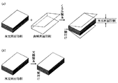
図8は、本実施形態における糊付け製本を説明する模式図である。 FIG. 8 is a schematic diagram illustrating gluing bookbinding in the present embodiment.
本実施形態の画像形成システム1000が具備するシート処理装置230は、糊付け製本処理を含む複数種類のシート処理(ステイプル処理、パンチ処理、シフト排紙処理、中綴じ製本処理、断裁処理、糊付け製本処理等)を、実行可能に構成されている。
The
尚且つ、本実施形態のシート処理装置230は、互いに異なる種類の第1タイプの糊付け製本処理と第2タイプの糊付け製本処理の少なくとも2種類を含む、複数種類のシート糊付け処理を、実行可能に構成されている。
In addition, the
例えば、本実施形態の画像形成システム1000は、第1タイプの糊付け製本処理として「くるみ製本処理」を、シート処理装置230により実行可能に構成されている。くるみ製本処理では、図8(a)に示すような出力物を作成させるよう本画像形成システムをCPU回路部122により制御する。
For example, the
くるみ製本対象のジョブを本画像形成システム1000にて処理する場合、以下のような、一連の処理動作を、本画像形成システム1000にて、実行させる。
When a case binding target job is processed by the
例えば、リーダ部1から入力したジョブの一連のプリントデータ、或いは、コネクタ121を介して外部装置から受信したジョブの一連のプリントデータを、画像メモリ120のハードディスクに格納させる。又、当該ジョブのくるみ製本における本文用のシートとしてユーザにより指定された所定のタイプのシート(第1タイプのシートと称す)を、画像形成装置本体が具備する複数の給紙部(214、215、225、226、227)のうちの、ユーザからの指示に基づいた給紙部から給送させる。次いで、給紙部からの第1タイプのシートに対して、上記画像メモリ120から読み出した当該ジョブのくるみ製本処理における本文用のプリントデータを、プリンタ部2によりプリントさせる。図8(a)の例では、本文用の複数のシートに、本文用の画像データを両面プリントさせた場合の例である。
For example, a series of print data of a job input from the
そして、更に、くるみ製本処理では、本文用のプリントデータがプリントされた複数枚の本文用のシートからなるシート束(このシート束を、第1タイプのシート束と称す)に対して糊付けユニット300により糊付け処理を実行させる。尚、この糊付け処理では、複数の本文用のシート(第1タイプのシート)同士を糊付けさせる。
Further, in the case binding process, a
次いで、更に、くるみ製本処理では、この糊付け処理済みの第1タイプのシート束(即ち、本文用の画像データがプリントされた本文用の複数枚のシートからなる一連のシート束)と、くるみ製本の表紙用のシートとしてユーザにより指定された、所定のタイプのシート(第2タイプのシートと称す)とを、1つの出力束として、糊付けユニット300により糊付けさせる。図8(a)にて真中に示す例が、くるみ製本表紙用のシート(このシートが、第2タイプのシートに相当)である。
Next, in the case binding process, the first type sheet bundle that has been subjected to the gluing process (that is, a series of sheet bundles composed of a plurality of text sheets on which image data for the text is printed) and case binding. A predetermined type of sheet (referred to as a second type of sheet) designated by the user as a cover sheet is glued by the gluing
尚、本実施形態は、如何なる方法で、第1タイプのシート束(本文用の画像がプリントされたシート束に相当)と第2タイプのシート(本文用のシート束をカバーする為の、くるみ製本用のカバーシートに相当)との糊付け処理を実行してもかまわない。 In this embodiment, the first type sheet bundle (corresponding to the sheet bundle on which the text image is printed) and the second type sheet (covering the text sheet bundle are used in any method. It is also possible to execute a gluing process with a bookbinding cover sheet.
しかし、最終的には、図8(a)の右端に示すような出力結果や、後述する図25〜図29のような印刷物2400が得られるように、シートの糊付け処理を実行させるよう、画像形成システム1000を制御する。
However, in the end, the image is subjected to the sheet gluing process so that an output result as shown at the right end of FIG. 8A or a printed
又、本実施形態の画像形成システム1000では、この第2タイプのシート(くるみ製本表紙用のシートに相当)を、画像形成装置本体が具備する複数の給紙部(214、215、225、226、227)のうちのユーザにより指定された給紙部から給送させ、シート処理装置230内部へと搬送可能に構成されている。
In the
そして、この第2タイプのシート(くるみ製本表紙用のシートに相当)に対して、プリンタ部2にて、くるみ製本表紙用の画像データを、プリントさせることも可能である。図8(a)の真中の例では、くるみ製本表紙用のシートに対して、くるみ製本表紙用の画像データを、プリンタ部2にてプリントさせた場合の例である。
The
勿論、この第2タイプのシート(くるみ製本表紙用のシート)に対して、くるみ製本表紙用の画像データが予めプリントされたシートを利用することも出来る。この場合、くるみ製本表紙用の画像データがプリント済みのシートを上記給紙部にユーザがセットしておけば、プリンタ部2にてプリント処理を実行させる必要はない。よって、この場合は、プリンタ部2では印刷せずに、そのまま、シート処理装置230内部へ第2タイプのシート搬送させるよう本画像形成システム1000を制御する。
Of course, a sheet on which image data for case binding cover is printed in advance can be used for the second type sheet (sheet for case binding cover). In this case, if the user sets a sheet on which image data for case binding cover has been printed in the sheet feeding unit, the
尚、このように、予め画像がプリントされたシートを第2タイプのシートとして利用する場合には、プリンタ部2内部を通過させずに、シート処理装置230内部へ紙搬送できるような、特別な給送装置(本実施形態では、このような給紙装置を、インサータと呼ぶ)を設けても良い。そして、第2タイプのシートが、予めプリント済みのシートであるならば、当該インサータから該シートを給送可能にするように本画像形成システムを構築しても良い。
As described above, when a sheet on which an image has been printed in advance is used as the second type sheet, a special sheet can be transported into the
又、本実施形態では、第2タイプのシートに対して、くるみ製本処理における表紙用の画像データをプリントするか否かをユーザ自身により決定可能にする為の操作画面を、表示部4−250に表示可能にCPU回路部122により制御する。そして、該画面等を介し、ユーザ自身により、くるみ製本モードにおける第2タイプのシートに対するプリント実行可否を選択可能に構成している。
In the present embodiment, an operation screen for allowing the user himself to decide whether or not to print the cover image data in the case binding process on the second type sheet is displayed on the display unit 4-250. Is controlled by the
尚、本実施形態において、くるみ製本処理における第1タイプのシートと、第2タイプのシートの関係に説明する。 In the present embodiment, the relationship between the first type sheet and the second type sheet in the case binding process will be described.
本実施形態において、第1タイプのシートと、第2タイプのシートとでは、シートの種類が異なり、且つ、シートのサイズも異なる。或いは、第1タイプのシートと、第2タイプのシートとでは、シートの種類は同じでも異なっていてもよいが、シートのサイズは異なる。即ち、本実施形態で詳述している、くるみ製本モードにおける、第1タイプのシートと第2タイプのシートは、少なくとも、互いに、サイズが異なるシートのことを意味する。特に、本実施形態では、第2タイプのシートは、第1タイプのシートよりもサイズの大きいシートである。 In the present embodiment, the first type sheet and the second type sheet have different sheet types and different sheet sizes. Alternatively, the first type sheet and the second type sheet may be the same or different, but the sheet size is different. That is, in the case binding mode, which is described in detail in the present embodiment, the first type sheet and the second type sheet mean at least sheets having different sizes. In particular, in the present embodiment, the second type sheet is a sheet having a larger size than the first type sheet.
第1タイプのシート束と第2タイプのシートとの糊付け処理では、次のような糊付け処理を行う。 In the gluing process between the first type sheet bundle and the second type sheet, the following gluing process is performed.
例えば、本文用の画像データがプリントされ且つ背表紙部分に糊付けされた第1シート束に対し、くるみ製本表紙用の画像データがプリントされた第2タイプのシートを、第1タイプのシート束の背表紙部分を中心に、第2タイプのシート(1枚)が、被い尽くすように、糊付けする。そして、最終的には、背表紙部分を中心に第2タイプのシートを折り畳む処理を実行する。この出力結果例が、図8(a)の右側の印刷結果例、或いは、後述する図25〜図29の印刷結果例に、相当する。 For example, a second type sheet on which image data for case binding covers is printed on a first sheet bundle in which image data for body text is printed and glued to the back cover part is used for the first type sheet bundle. Gluing is performed so that the second type sheet (one sheet) is covered around the spine portion. Finally, a process of folding the second type sheet around the spine portion is executed. This output result example corresponds to a print result example on the right side of FIG. 8A or a print result example shown in FIGS.
このように、本実施形態の画像形成システム1000は、第1タイプのシート糊付け処理として、くるみ製本処理を、シート処理装置230により実行可能に構成されている。
As described above, the
次に、第1タイプの糊付け処理とは異なる種類の糊付け処理に相当する、本画像形成システムが実行可能な、第2タイプのシート糊付け処理について説明する。 Next, a second type of sheet gluing process that can be executed by the image forming system, which corresponds to a different type of gluing process from the first type of gluing process, will be described.
例えば、本実施形態の画像形成システム1000は、第2タイプの糊付け製本処理として「天糊製本処理」を実行可能に構成されている。
For example, the
本実施形態において、天糊製本対象のジョブを本画像形成システム1000にて処理する場合に、例えば、以下のような一連の処理動作を、本画像形成システム1000にてCPU回路部122により、実行させる。
In the present embodiment, when processing a job to be bound by the top glue using the
まず、リーダ部1から入力したジョブの一連のプリントデータ、或いは、コネクタ121を介して外部装置から受信したジョブの一連のプリントデータを、画像メモリ120のハードディスクに格納させる。又一方で、当該ジョブの天糊製本における本文用のシートとしてユーザにより指定された所定のタイプのシート(第1タイプのシートに相当する)を、画像形成装置本体が具備する複数の給紙部(214、215、225、226、227)のうちの、ユーザからの指示に基づいた給紙部から給送させる。そして、この給紙部からの第1タイプのシートに対して、上記画像メモリ120から読み出した当該ジョブの天糊製本処理における本文用のプリントデータを、プリンタ部2によりプリントさせる。図8(b)の例では、本文用の複数のシートに、本文用の画像データを両面プリントさせた場合の例である。
First, a series of print data of a job input from the
そして、更に、天糊製本処理では、本文用のプリントデータがプリントされた複数枚の本文用のシートからなるシート束(第1タイプのシート束に相当)に対して糊付け処理を実行するよう糊付けユニット300を制御する。
Further, in the top glue binding process, the gluing process is performed so that the gluing process is performed on a sheet bundle (corresponding to the first type sheet bundle) composed of a plurality of text sheets on which print data for the text is printed. The
以上の処理は、上述の「くるみ製本処理」と基本的に同じである。しかし、「天糊製本処理」を実行する場合には、上述の「くるみ製本処理」にて実行させる処理のうちの以下の処理を禁止するよう、例えば、CPU回路部122により、本画像形成システム1000を制御する。
The above processing is basically the same as the “case binding processing” described above. However, when the “sheet binding process” is executed, the
例えば、天糊製本処理では、CPU回路部122は、表紙用のシート(第2タイプのシートに相当)を用いる事を禁止する。具体的には、CPU回路部122は、天糊製本処理モードにて、本文用の画像データがプリントされた第1シート束に対して第2タイプのシートを糊付けすることを禁止するよう制御する。しかも、CPU回路部122は、天糊処理処理モードにて処理対象のジョブの処理にて、くるみ製本モードにて利用すべき第2タイプのシートを給紙部(214、215、225、226、227)から給送すること自体も禁止する。当然、CPU回路部122は、天糊製本モードにおいて第2タイプのシートに対するプリント処理も禁止する。
For example, in the sheet binding process, the
図8(b)の右側の例は、この天糊製本処理にて作成した最終成果物の例を示す。天糊製本処理と上述のくるみ製本処理とでは、夫々、糊付け処理方法を異ならせるよう制御する。 The example on the right side of FIG. 8B shows an example of the final product created by this top glue binding process. The top glue binding process and the case binding process described above are controlled so that the gluing process method is different.
例えば、第1タイプのシート束(本文用の画像データがプリントされた複数枚のシートからなるシート束に相当)同士での糊付け処理を実行させる点では、くるみ製本と同じである。しかし、くるみ製本処理モードでは実行させる第2タイプのシートの糊付け処理(図8(a)参照)を、天糊製本処理モードにおいて実行する事は、禁止する。天糊製本処理では、図8(b)のように、本文用のシート束のみで糊付け処理を完了させるように、シート処理装置230及びプリンタ部2等を、CPU回路部122により制御する。
For example, this is the same as case binding in that the first type of sheet bundle (corresponding to a sheet bundle made up of a plurality of sheets printed with text image data) is executed. However, it is prohibited to execute the second-type sheet gluing process (see FIG. 8A) to be executed in the case binding process mode in the top-binding process mode. In the sheet binding process, as shown in FIG. 8B, the
このように、本画像形成システムは、第1タイプの糊付け処理とは異なる第2タイプの糊付け処理として、天糊製本処理を、シート処理装置230により実行可能に構成している。
As described above, the image forming system is configured so that the
以上のような構成を前提とし、本実施形態の画像形成システム1000は、ユーザインタフェースユニット(本実施形態では、表示部4−250や、操作部123等)を介して、くるみ製本処理モード、及び、天糊製本処理モードのうちの、ユーザが所望の糊付け処理モードを、ユーザ自身により選択可能に構成している。CPU回路部122は、上記2種類の糊付け処理モードのうちの、ユーザにより選択された処理モードに応じた糊付け処理を、実行させるように、本画像形成システムを制御する。
Based on the above configuration, the
次に、図8(a)を用いて説明した、表紙をつける糊付け処理モードに相当する「くるみ製本」に関係する、各種処理について、具体例をもって、更に説明する。 Next, various processes related to “case binding” corresponding to the gluing processing mode for attaching a cover described with reference to FIG. 8A will be further described with specific examples.
図24〜図35は、本実施形態にて制御対象となる、シート糊付け処理の一例の「くるみ製本処理」に関する説明図であり、同一のものには同一の符号を付してある。 FIGS. 24 to 35 are explanatory diagrams regarding “case binding processing” as an example of sheet gluing processing to be controlled in this embodiment, and the same components are denoted by the same reference numerals.
ここでは、くるみ製本処理対象となるジョブのデータ発生源は、自装置のリーダ部1とする。そして、リーダ部1にセットされた原稿のプリント処理を行い、該プリント処理によりプリントされたシートに対してシート処理装置230によりくるみ製本処理する場合における、一連の処理手順について説明する。
Here, it is assumed that the data generation source of the job to be subjected to the case binding process is the
まず、操作部123の表示部4−250に表示させた図4の画面の応用モードキー4−260がユーザにより押下されたとする。これを受け、CPU回路部122は、表示部4−250に、図6(a)の画面を表示させる。次に、図6(a)の画面のキー801を介してユーザにより「製本モード」が選択されたとする。これを受け、CPU回路部122は、図6(b)の画面を表示させた後に、図6(c)の画面を表示部4−250に表示させる。
First, it is assumed that the application mode key 4-260 on the screen of FIG. 4 displayed on the display unit 4-250 of the
そして、図6(c)の画面のキー803を介して「糊付け製本する」指示がユーザにより入力され、且つ、後述する図7(f)の画面を介して「表紙の設定」がユーザによりなされたとする。 Then, a “glued bookbinding” instruction is input by the user via the key 803 on the screen of FIG. 6C, and “cover setting” is made by the user via the screen of FIG. Suppose.
このように、糊付け製本モードがユーザにより選択された場合において、本文画像データを印刷したシートに対して表紙をつける設定が、ユーザにより指示された場合には、CPU回路部122は、当該ユーザ設定に従い処理すべき処理対象のジョブを、「くるみ製本処理を実行すべきジョブ」であると判断する。即ち、この例では、糊付け製本モードがユーザにより選択され、且つ、該モードにて「表紙をつける」設定がユーザにより選択された事を条件に、CPU回路部122は、くるみ製本処理モードを実行すべきジョブであると判断する。
As described above, when the glue binding mode is selected by the user, when the user instructs the setting of attaching a cover to the sheet on which the text image data is printed, the
上述の処理対象となるジョブに対するユーザの各種印刷処理条件の設定が完了したとする。そのうえで、図4の操作部123のスタートキー4−242がユーザにより押下されたとする。この時点で、CPU回路部122は、ジョブ処理の開始要求指示の入力有りと判断する。そして、当該ユーザからの指示に基づき、リーダ部1の原稿給送装置101にユーザにより載置済みの原稿束を、先頭ページから順次、1枚ずつ、リーダ部1のプラテンガラス上の読取位置へ給送させ、当該ジョブの原稿の読取処理をリーダ部1により実行させるように、CPU回路部122により、リーダ部1を制御する。且つ、CPU回路部122は、これらの読取データを、くるみ製本処理における本文用(中身)の画像データとして、画像メモリ120のハードディスクに順次記憶させるよう画像メモリ120等を制御する。
It is assumed that the user has set various print processing conditions for the job to be processed. Then, it is assumed that the user presses the start key 4-242 of the
尚、この記憶したデータを印刷した結果が、例えば、図8(a)の「本文用両面印刷」に相当する。図8(a)では本文用の出力結果が「両面印刷」になっている。しかし、くるみ製本処理において、本文用の画像を印刷するシートに対して必ずしも両面印刷を実行する必要はない。なぜなら、くるみ製本印刷モードにおいて、本文に相当する個所は両面プリントさせたいユーザもいれば、本文に相当する個所を片面プリントさせたユーザ等、様々なユーザニーズが存在するからである。 The result of printing the stored data corresponds to, for example, “double-sided printing for text” in FIG. In FIG. 8A, the output result for the text is “double-sided printing”. However, in case binding processing, it is not always necessary to execute double-sided printing on a sheet on which a text image is printed. This is because, in the case binding printing mode, there are various user needs such as a user who wants to double-side print a part corresponding to the text and a user who prints a part corresponding to the text on one side.
そこで、例えば、本画像形成システム1000において、くるみ製本において、本文用の画像を印刷するシート(第1タイプのシートに相当)に対して片面印刷するか両面印刷するかを、図4の画面のキー4−258を介してユーザ自身により選択決定可能に構成しても良い。
Therefore, for example, in the case of bookbinding in the
又、くるみ製本処理の表紙用のシート(第2タイプのシートに相当)を、本実施形態では、例えば、本画像形成装置の手差し給紙部227に、ユーザにより、セットさせる。且つ、この第2タイプのシートを選択する為に、表紙用のシートをユーザが表示部4−250を介して選択する際に、手差し給紙部227に対応する給紙部を選択出来るようにする。これにより、第2タイプのシートを、該手差し給紙部から給送させる事も可能にする。
Further, in this embodiment, a cover sheet for the case binding process (corresponding to a second type sheet) is set by the user, for example, in the
又、本画像形成装置、或いは、別の印刷装置において、くるみ製本処理の表紙用のシートに対して、くるみ製本表紙用の画像データを予めプリントしておく。そして、表紙表示用画像がプリント済みの当該シートを、本画像形成システムにて、くるみ製本処理対象のジョブを処理するに先立ち、本画像形成装置の給紙部に対して、ユーザにより、セットさせる。そして、このシートを利用するよう操作部123を介してユーザにより処理条件を設定させておく。これにより、当該くるみ製本処理対象のジョブを処理する際に、くるみ製本表紙用のシートに対して印刷処理を実行する必要は無い。
Further, in this image forming apparatus or another printing apparatus, image data for case binding cover is printed in advance on the cover sheet for case binding processing. Then, the user sets the sheet on which the cover display image has been printed on the paper feeding unit of the image forming apparatus prior to processing the case binding processing target job in the image forming system. . Then, the processing conditions are set by the user via the
尚、第2タイプのシートとして既にプリント済みのシートを利用する場合に、上述のようなインサータを本画像形成システム1000が具備している場合には、該インサータから該第2タイプのシートを給送可能に構成しても良い。この場合には、第2タイプのシートの給紙部として該インサータを選択可能にする表示画面を、表示部4−250に、表示できるよう、CPU回路部122により制御する。そして、該画面を介して、第2タイプのシートの給送源として、インサータをユーザにより選択可能にする。
When a sheet that has already been printed is used as the second type sheet and the
以上のように、第2タイプのシートに対して既に表紙用の画像データがプリントされているような状況の場合には、本実施形態では、リーダ部1により読取動作が実行された上記ジョブの読取り画像データは、全ページ、本文用の原稿画像データとする。
As described above, in the case where the image data for the cover is already printed on the second type sheet, in the present embodiment, the job of which the reading operation is executed by the
一方、くるみ製本処理を実行すべきジョブの一連の処理工程において、くるみ製本用の表紙に対して表紙用の画像データをプリントする処理が必要な場合には、CPU回路部122は、以下のような、処理を画像形成装置に実行させる。
On the other hand, in a series of processing steps of a job to execute case binding processing, when processing for printing image data for a cover on a cover for case binding is necessary, the
例えば、ユーザにより操作部123を介して、くるみ製本モードが選択され、且つ、表紙となる第2タイプのシートに相当するシートに対して表紙用の画像をプリントさせる指示が入力されたとする。
For example, it is assumed that the case binding mode is selected by the user via the
この場合、CPU回路部122は、リーダ部1により読取られる複数ページからなる一連の原稿束のうちの先頭ページの原稿画像に相当する画像データを、表紙用の原稿画像として、画像メモリ120のハードディスクに格納させる。次いで、当該ページに後続するページ(例えば、2ページ目以降のページ)の原稿画像データについては、本文用の原稿画像データとして、上記表紙用の画像データと関連付けて、順次、該ハードディスクに格納させる。
In this case, the
尚、くるみ製本処理対象のジョブにおいて、くるみ製本表紙用のシート(第2タイプのシートに相当)の表表紙となる個所に表表紙用の画像をプリントさせ、且つ、当該シート裏表紙となる個所に裏表紙用の画像データをプリントさせる事も出来る。このような、処理を希望するユーザにも対処すべく、CPU回路部122により、次のような制御を、実行しても良い。
In a case binding job, a cover cover image is printed on a portion that becomes a cover of a case binding cover sheet (corresponding to a second type sheet), and a portion that becomes the back cover of the sheet. You can also print image data for the back cover. In order to deal with such a user who desires processing, the
例えば、ユーザが表紙の設定を表示部4−250にて実行する際に、「くるみ製本の表紙用のシートに、表表紙画像と裏表紙画像の両方をプリントさせる」等の指示をユーザにより入力可能にする表示キーを具備した表示画面を、表示部4−250に表示させる。そして、当該画面を介して上記指示が入力された事に応答し、上述の処理を実行させるようプリンタ部2を制御する。
For example, when the user executes cover setting on the display unit 4-250, the user inputs an instruction such as “print both the front cover image and the back cover image on the case binding cover sheet”. A display screen having a display key to be enabled is displayed on the display unit 4-250. In response to the input of the instruction via the screen, the
このような設定がなされた場合、リーダ部1により読取った複数ページからなる一連の原稿束のうちの、1頁目の原稿に相当する画像データを、表表紙用の原稿画像として、画像メモリ120のハードディスクに格納させる。更に、当該ジョブの2頁目の原稿に相当する画像データを、裏表紙用の原稿画像として、画像メモリ120のハードディスクに格納させる。そして、当該ジョブの残りのページに相当する原稿画像データを、本文用の原稿画像データとして、上記表表紙用の画像データ並びに裏表紙用の画像データと関連付けて、該ハードディスクに格納させておく。
When such a setting is made, image data corresponding to the original of the first page in a series of original bundles composed of a plurality of pages read by the
尚、くるみ製本モードが選択された場合において、例えば、10頁からなる一連の原稿束をリーダ部1で連続して読取る場合に、1番目に読取った原稿を、第2タイプのシート(表紙用のシートに相当)にプリントすべき表表紙用の画像データとして、画像メモリ120に、登録させる。次いで、2番目〜9番目に読取った各原稿データを、第1タイプのシート(本文用のシートに相当)にプリントすべき本文用の1頁目〜8頁目の画像データとして、画像メモリ120に登録させる。そして、最後に読取った10枚目の原稿を、上記第1タイプのシートにプリントすべき裏表紙用の画像データとして、画像メモリ120に、登録させる。そして、CPU回路部122は、これらの画像データを関連付けて管理しておく。このように、裏表紙用の原稿画像データを、原稿束の最後に登録するようなデータ記憶方法であっても良い。即ち、くるみ製本処理印刷が全て完了し、最終的な、くるみ製本印刷物のページ順序と同じ順序で、処理対象の画像データを画像メモリ120に登録させるように制御する構成でも良い。
When the case binding mode is selected, for example, when a series of original pages consisting of 10 pages are continuously read by the
但し、本実施形態は、使い勝手を向上させるという観点で、上述のような制御例を採用するが、本実施形態はこれに限定されるものではない。例えば、次のような制御を本画像形成システム1000で実行できるならば、如何なる構成であってもよい。
However, this embodiment employs the above control example from the viewpoint of improving usability, but the present embodiment is not limited to this. For example, any configuration is possible as long as the following control can be executed by the
例えば、処理すべき複数ページからなる一連の画像データのうちの、表表紙用のデータに相当する原稿画像データと裏表紙用のデータに相当する原稿画像データとが、第2タイプのシート(くるみ製本処理における表紙用のシートに相当)の同一面上にプリントされるように制御する。そして、当該一連の画像データのうちの、本文用のデータに相当する複数ページの原稿画像データが、複数枚の第1タイプのシート(くるみ製本処理における本文用の各シートに相当)に、プリントされるように、リーダ部1や画像メモリ部120やプリンタ部2等をCPU回路部122により制御する。そして、ユーザがくるみ製本の表紙用の画像として所望するプリントデータを、くるみ製本の表紙用のシートに、プリントさせ、ユーザがくるみ製本の本文用の画像として望むプリントデータを、本文用のシートに対してプリントできるように構成する。
For example, out of a series of image data consisting of a plurality of pages to be processed, document image data corresponding to the data for the front cover and document image data corresponding to the data for the back cover are the second type sheets (cases). Control is performed so that printing is performed on the same surface (corresponding to a cover sheet in bookbinding processing). Then, a plurality of pages of document image data corresponding to the text data in the series of image data are printed on a plurality of first type sheets (corresponding to the text sheets in the case binding process). As described above, the
このような構成を実現できるのであるならば、リーダ部1による原稿の読取順序、画像メモリ120への原稿画像データの記憶順序並びに画像メモリ120からの原稿画像データの読出順序、プリンタ部2での原稿画像データのプリント順序等の各種動作シーケンスは問わない。これは、外部装置(例えば、図2の2002)から受け付ける、くるみ製本対象のジョブのプリントデータについても同様である。
If such a configuration can be realized, the reading order of the originals by the
又、更に、本画像形成システム1000のような、シートの糊付け処理を実行できる装置やシステムにおいて、当該糊付け処理に関わる様々なユーザからの様々なユーザニーズに対応出来るようにするという効果を、更に一層向上させるべく、本実施形態において上記制御を更に応用しても良い。
Further, in the apparatus or system capable of executing the sheet gluing process, such as the
例えば、本実施形態の画像形成システムのCPU回路部122は、以下のような処理を実行するよう、本画像形成システム1000を制御する。
For example, the
例えば、くるみ製本モードが表示部4−250を介してユーザにより選択された場合において、図7(f)の表示画面を表示部4−250に表示させる。 For example, when the case binding mode is selected by the user via the display unit 4-250, the display screen in FIG. 7F is displayed on the display unit 4-250.
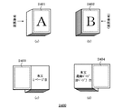
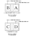
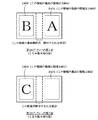
本実施形態では、くるみ製本処理対象のジョブを処理した場合に、くるみ製本印刷物(例えば、図24(a)に示す、くるみ製本印刷結果物2400を参照)における表表紙のページに該当する紙面(図24の例で言えば、領域2401の部分)に対して、くるみ製本印刷物における本文用のプリントデータとは異なる、第1の所定のプリントデータ(本実施形態では、これを、くるみ表紙物における表面用の画像データと呼ぶ)をプリントすべきか否かを、図7(f)の各種表示キーを具備した表示画面を介して、ユーザにより設定可能に構成している。
In the present embodiment, when a case binding process target job is processed, a paper surface corresponding to a front cover page in a case binding printed material (see, for example, a case binding
例えば、図7(f)の表示画面の「表紙のオモテにコピーする」キーがユーザにより押下された場合には、くるみ製本印刷結果における表紙(ここでいう、表紙とは、くるみ製本印刷を実行した結果を基準に説明している)のページに該当する紙面(図24(a)の例で説明すると、領域2401に部分)に対して、くるみ製本印刷物における表紙用の画像データを、プリンタ部2によりプリントさせる。一方、例えば、図7(f)の画面の「表紙のオモテにコピーしない」キーが押下された場合には、くるみ製本印刷結果における表紙のページに該当する紙面に対して、プリンタ部2により、当該第1の所定のプリントデータをプリントする事を禁止する。
For example, when the user presses the “Copy to Front Cover” key on the display screen of FIG. 7F, the cover in the case binding printing result (here, the front cover is the case binding printing). The image data for the cover in the case binding print is printed on the page corresponding to the page of the page (described in the example of FIG. 24A). 2 to print. On the other hand, for example, when the “Do not copy to front cover” key on the screen of FIG. 7F is pressed, the
このように、本画像形成システム1000では、くるみ製本モードにて、第1の特殊印刷処理を実行可能にする。
As described above, the
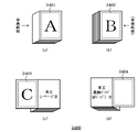
更に、本実施形態では、くるみ製本印刷物を、正立状態からみて、表表紙側から表表紙のみをユーザが1枚めくった直後のページに該当する紙面(例えば、図24(C)を用いて説明すると、領域2403の部分に相当)に対して、先程と同様に、くるみ製本印刷物における本文用のプリントデータには該当しない、第2の所定のプリントデータ(本実施形態では、これを、くるみ製本物における表紙の裏用の画像データと呼ぶ)を、プリントすべきか否かを、図7(f)の各種表示キーを具備した表示画面を介して、ユーザにより設定可能にする。 Furthermore, in the present embodiment, the case binding printed matter is viewed from the upright state, and the page corresponding to the page immediately after the user turns only one cover from the front cover side (for example, using FIG. 24C). For example, the second predetermined print data (corresponding to the area 2403), which does not correspond to the print data for the main body in the case binding printed material (in this embodiment, this is the case). Whether or not to print the image data for the back of the front cover in the bookbinding product can be set by the user via the display screen provided with various display keys of FIG.
例えば、図7(f)の表示画面の「表紙のウラにコピーする」キーがユーザにより押下された場合には、くるみ製本印刷結果を、正立状態からみて、表表紙側から表表紙のみを1枚だけユーザがめくった直後のページに該当する紙面(例えば、図24(C)を用いて説明すると、領域2403の部分に相当)に対して、くるみ製本印刷物における表紙の裏用の画像データを、プリンタ部2によりプリントさせる。一方、例えば、図7(f)の画面の「表紙のウラにコピーしない」キーが押下された場合には、くるみ製本印刷結果における表紙をめくった直後のページに該当する当該紙面に対して、プリンタ部2による当該第2の所定のプリントデータのプリント処理の実行を禁止する。
For example, when the user presses the “copy to cover cover” key on the display screen of FIG. 7F, the case binding print result is viewed from the front cover side only in the case of the case binding printing result. Image data for the back of the front cover of the case binding printed material for the paper surface corresponding to the page immediately after the user turned over (for example, the
このように、本画像形成システム1000では、くるみ製本モードにて、第2の特殊印刷処理を実行可能にする。
As described above, the
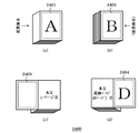
そして、更に、本実施形態では、くるみ製本印刷物を、正立状態からみて、ユーザが、裏表紙側から裏表紙のみを、1枚だけ、めくった直後のページに該当する紙面(例えば、図24(d)を用いて説明すると、領域2404の部分に相当)に対して、先程と同様に、くるみ製本印刷物における本文用のプリントデータには非該当の、第3の所定のプリントデータ(本実施形態では、これを、くるみ製本物における裏表紙の表用の画像データと呼ぶ)を、プリントすべきか否かを、図7(f)の各種表示キーを具備した表示画面を介して、ユーザにより設定可能にする。 Further, in the present embodiment, when the case binding printed material is viewed from the upright state, only one sheet of the back cover is turned from the back cover side by the user, and the page corresponding to the page immediately after turning (for example, FIG. 24). In the case of (d), the third predetermined print data (this embodiment is not applicable to the print data for the text in the case binding printed material) as in the previous case. In the form, this is called image data for the front cover of the back cover in the case binding product) whether or not to print is determined by the user via the display screen having various display keys in FIG. Make it configurable.
例えば、図7(f)の表示画面の「裏表紙のオモテにコピーする」キーがユーザにより押下された場合には、くるみ製本印刷物を、正立状態からみて、裏表紙側から裏表紙のみを1枚だけユーザがめくった直後のページに該当する紙面(例えば、図24(d)を用いて説明すると、領域2404の部分に相当)に対して、くるみ製本物における裏表紙の表用の画像データを、プリンタ部2によりプリントさせる。一方、図7(f)の画面の「裏表紙のオモテにコピーしない」キーが押下された場合には、くるみ製本印刷結果における裏表紙側から裏表紙をめくった直後のページに該当する当該紙面に対して、プリンタ部2により、当該第3の所定のプリントデータのプリント処理を実行することを禁止する。
For example, when the “copy to the back cover front” key on the display screen in FIG. 7F is pressed by the user, the case binding printed material is viewed from the upright state, and only the back cover is viewed from the back cover side. A front cover front image in case binding on a paper surface corresponding to a page immediately after the user turns only one sheet (for example, the
このように、本画像形成システム1000では、くるみ製本モードにて、第3の特殊印刷処理を実行可能にする。
As described above, the
そして、更に、本実施形態では、くるみ製本印刷物における裏表紙のページに該当する紙面(例えば、図24(b)を用いて説明すると、領域2402の部分に相当)に対して、先程と同様に、くるみ製本印刷物における本文用のプリントデータとしてはユーザにより利用されない、第4の所定のプリントデータ(本実施形態では、これを、くるみ表紙物における表面用の画像データと呼ぶ)をプリントすべきか否かを、図7(f)の各種表示キーを具備した表示画面を介して、ユーザにより設定可能にする。
Further, in the present embodiment, the paper surface corresponding to the back cover page in the case-bound printed matter (for example, corresponding to the
例えば、図7(f)の表示画面の「裏表紙のウラにコピーする」キーがユーザにより押下された場合には、くるみ製本印刷結果における裏表紙のページに該当する紙面(例えば、図24(b)を用いて説明すると、領域2402の部分に相当)に対して、くるみ製本印刷物における裏表紙用の画像データを、プリンタ部2によりプリントさせる。一方、例えば、図7(f)の画面の「裏表紙のウラにコピーしない」キーが押下された場合には、くるみ製本印刷結果における裏表紙のページに該当する紙面に対して、プリンタ部2により、当該第4の所定のプリントデータをプリントする事を禁止する。
For example, when the user presses the “copy to back cover back” key on the display screen of FIG. 7F, the paper surface corresponding to the back cover page in the case binding printing result (for example, FIG. When using b), the image data for the back cover in the case binding print is printed by the
このように、本画像形成システム1000では、くるみ製本モードにて、第4の特殊印刷処理を実行可能にする。
As described above, the
以上説明したように、本実施形態の画像形成システムでは、くるみ製本モードがユーザにより設定されたジョブを本画像形成システム1000にて処理する場合において、本文用のシート(第1タイプのシート)に対する本文用の画像データの一連のプリント処理を、プリンタ部2により、実行させるだけに留まらない。尚、本文用のプリントデータを、本文用のシート(第1タイプのシート)にプリントする一連の処理は、くるみ製本モードにおける第1のプリントモードと呼ぶ(あるいは、くるみ製本モードにおける第1プリントシーケンスと称す)。
As described above, in the image forming system of the present embodiment, when the case binding mode is processed by the
本実施形態の画像形成システム1000では、くるみ製本処理対象のジョブにて、くるみ製本モードにおける上記第1のプリントモードを実行可能にするのみならず、該モードと共に、ユーザが本文用の画像データとしては取り扱わないデータに該当する所定のプリントデータの、くるみ製本用のシートに対する、プリント処理を、少なくとも含んだ、特別な一連のプリント処理(上記例だと、4種類の特殊なプリントシーケンスを有している)を、実行可能に、本画像形成システムを、CPU回路部122により、制御している。尚、本文用のプリントデータには該当しない上記所定のプリントデータの一連のプリント処理を、くるみ製本モードにおける第2のプリントモードと呼ぶ(或いは、くるみ製本モードにおける第2プリントシーケンスと称す)。
In the
しかも、上述のように、図7(f)の表示画面のような画面を、ユーザインタフェースユニットに提示させるように、CPU回路部122により制御することで、くるみ製本モードにおいて、上記第1プリントシーケンスと上記第2のプリントシーケンスの両方を実行させるか、上記第1プリントシーケンスのみを実行させるかを、くるみ製本モードを選択したユーザ自身により選択可能に構成している。
In addition, as described above, the first print sequence is performed in the case binding mode by controlling the screen such as the display screen of FIG. 7F by the
上記第1のプリントシーケンスや第2プリントシーケンスを活用することで、例えば、ある新商品のカタログや説明書や、ある程度のボリュームのある企業内向け研修用の資料や、公共団体用ガイドブック等、様々な種類の、様々なレイアウトの、多種多様なくるみ製本物を、本画像形成システムにて、作成することも出来る。例えば、その一例として、図25〜図35等を用いて、本画像形成システム1000にて実行可能な、くるみ製本印刷処理の例を、5種類説明する。
By using the first print sequence and the second print sequence, for example, catalogs and manuals for certain new products, training materials for companies with a certain volume, guidebooks for public organizations, etc. Various kinds of various bookbinding products of various types and various layouts can be created by the image forming system. For example, as an example, five types of case binding printing processes that can be executed by the
尚、上述の例では、くるみ製本モードにて、本文用の為のプリントデータには該当しない、4つの所定のプリントデータが存在した。 In the above example, in the case binding mode, there are four predetermined print data that do not correspond to the print data for the text.
従って、図25〜図35を用いた説明では、上記第1の所定のプリントデータを、画像Aとする。同様に、第2の所定のプリントデータを、画像Cとする。同様に、第3の所定のプリントデータを、画像Dとする。同様に、第4のプリントデータを、ここでは、画像Bとする。又、この例の「くるみ製本モード」における本文用のプリントデータは、合計Mページ分存在するとする。 Therefore, in the description using FIGS. 25 to 35, the first predetermined print data is the image A. Similarly, the second predetermined print data is an image C. Similarly, the third predetermined print data is an image D. Similarly, the fourth print data is an image B here. Further, it is assumed that the print data for the text in the “case binding mode” in this example exists for a total of M pages.
尚、第1〜第4の所定のプリントデータ画像A〜Dと、本文用のプリントデータ(1ページ目〜Mページ目の合計Mページ分のプリントデータ)は、リーダ部1或いは外部装置2002から入力される。これらのデータは1つのジョブとして、関連付けられて、画像メモリ120のハードディスクに格納させる。
The first to fourth predetermined print data images A to D and the text print data (print data for a total of M pages from the first page to the M page) are received from the
このような前提として、例えば、処理対象のジョブに対する設定として以下の一連の設定を、ユーザが実行したとする。 As such a premise, for example, it is assumed that the user executes the following series of settings as settings for a job to be processed.
まず、1番目の例について説明する。図7(f)の設定画面の「表紙のオモテにコピーする」キーをユーザが押下することで、くるみ製本モードにて、第2タイプのシートの領域2401に、画像Aを印刷させるべく、上述の第1の特殊印刷処理の実行指示を入力した。
First, the first example will be described. When the user presses the “Copy to Front Cover” key on the setting screen in FIG. 7F, the image A is printed in the second
尚且つ、図7(f)の設定画面の「表紙のウラにコピーする」キーをユーザが押下することで、くるみ製本モードにて、第2タイプのシートの領域2403に、画像Cを印刷させるべく、上述の第2の特殊印刷処理の実行指示を入力した。
In addition, when the user presses the “copy to cover cover” key on the setting screen of FIG. 7F, the image C is printed in the
尚且つ、図7(f)の設定画面の「裏表紙のオモテにコピーする」キーをユーザが押下することで、くるみ製本モードにて、第2タイプのシートの領域2404に、画像Dを印刷させるべく、上述の第3の特殊印刷処理の実行指示を入力した。
In addition, when the user presses the “copy to the back cover front” key on the setting screen of FIG. 7F, the image D is printed in the
尚且つ、図7(f)の設定画面の「裏表紙のウラにコピーする」キーをユーザが押下することで、くるみ製本モードにて、第2タイプのシートの領域2402に、画像Bを印刷させるべく、上述の第4の特殊印刷処理の実行指示を入力した。
In addition, when the user presses the “Copy to Back Cover Back” key on the setting screen of FIG. 7F, the image B is printed in the
以上のような、くるみ製本モードにおける一連の印刷設定がユーザにより操作部123を介して実行された事に応答して、CPU回路部122は、図25に示すような、くるみ印刷製本結果2400を作成するよう、当該くるみ製本印刷対象のジョブを、本画像形成システム1000により処理させる。
In response to a series of print settings in the case binding mode as described above being executed by the user via the
尚、図25(a)〜(d)の印刷結果2400の参照の仕方は、図24(a)〜(d)の印刷結果2400の参照の仕方と同様である。
Note that the way of referring to the
即ち、CPU回路部122は、図25に示す印刷結果2400を得るために、当該くるみ製本モードにおける、くるみ製本印刷処理として、以下の二種類の印刷処理をプリンタ部2に実行させる。
That is, the
まず、当該くるみ製本印刷ジョブにおける第1のプリントシーケンスとして、画像メモリ120のハードディスクに格納させた当該くるみ製本印刷処理対象のジョブのデータに含まれる本文用のプリントデータを、第1タイプのシートに対して、プリントするように、プリンタ部2を制御する。この一連のプリント動作を、本文用のページ数分、実行させる。この例では、合計Mページ分のプリント処理を実行させる。
First, as the first print sequence in the case binding print job, the text print data included in the data of the case binding print target job stored in the hard disk of the
尚且つ、CPU回路部122は、上記第1のプリントシーケンスを実行するだけでなく、当該くるみ製本印刷ジョブにおける第2のプリントシーケンスとして、当該くるみ製本印刷ジョブの本文用のプリントデータに関連付けて画像メモリ120のハードディスクに格納させた、上記画像A、画像B、画像C、画像Dの4つの所定のプリントデータを、第2タイプのシートの各領域2401〜2404に、プリントするようにプリンタ部2を制御する。
Further, the
図25に示す印刷結果2400を作成するにあたり、CPU回路部122は、第2タイプのシートに対する一連のプリント工程において、次のような印刷処理を実行させる。
In creating the
本文用のプリントデータがプリントされた第1タイプのシート束に糊付けされる前の第2タイプのシートの状態は、図30に示すように、2つ折りされる前の状態にある。 The state of the second type sheet before being glued to the first type sheet bundle on which the print data for the text is printed is in a state before being folded in half as shown in FIG.
図25に示すような印刷結果を得る為に、CPU回路部122は、図31に示すような印刷処理をプリンタ部2に実行させる。
In order to obtain a printing result as shown in FIG. 25, the
即ち、第2タイプのシートの第1面の領域2401に画像Aが配置され、且つ、該第2タイプのシートの第1面の領域2402に画像Bが配置されるように、第2タイプのシートの第1面に対するプリント処理をプリンタ部2に実行させる。
That is, the second type sheet is arranged so that the image A is arranged in the
尚、CPU回路部122は、画像Aと画像Bが1ページ分のデータになるように、画像編集処理に利用可能なメモリを用いて、レイアウト処理を実行させたうえで、該画像Aと画像Bとが1ページ分の画像データに編集処理された当該画像データを、プリンタ部2により、第2タイプのシートの第1面に対して、プリントさせる。
The
尚且つ、第2タイプのシートの第2面(第1面の裏側)の領域2403に画像Cが配置され、且つ、該第2タイプのシートの第2面の領域2404に画像Dが配置されるように、第2タイプのシートの第2面に対するプリント処理をプリンタ部2に実行させる。
In addition, the image C is arranged in the
尚、CPU回路部122は、画像Cと画像Dが1ページ分のデータになるように、画像編集処理に利用可能なメモリを用いて、レイアウト処理を実行させたうえで、該画像Cと画像Dとが1ページ分の画像データに編集処理された当該画像データを、プリンタ部2により、第2タイプのシートの第2面に、プリントさせる。
The
以上のような、第2タイプのシートに対する一連のプリント処理を実行させる。その上で、本文用のプリントデータ(合計Mページ分のプリントデータ)がプリントされた複数の第1タイプのシートからなる第1タイプのシート束に対して、当該プリント処理済みの第2タイプのシートを、糊付けユニット300により、糊付け処理させる。
A series of print processes for the second type sheet as described above are executed. After that, the second type of the second type that has undergone the printing process is applied to the first type of sheet bundle composed of a plurality of first type sheets on which the print data for the body (print data for a total of M pages) is printed. The sheet is subjected to a gluing process by the gluing
これにより、図25に示すような、くるみ製本印刷物2400を、本画像形成システム1000にて作成することが出来る。
As a result, a
次に、2番目の例について説明する。例えば、図7(f)の設定画面にてユーザが以下のような一連の印刷設定を行ったとする。 Next, a second example will be described. For example, assume that the user performs the following series of print settings on the setting screen of FIG.
まず、図7(f)の設定画面の「表紙のオモテにコピーする」キーをユーザが押下することで、くるみ製本モードにて、第2タイプのシートの領域2401に、画像Aを印刷させるべく、上述の第1の特殊印刷処理の実行指示を入力した。
First, when the user presses the “Copy to Front Cover” key on the setting screen of FIG. 7F, the image A should be printed on the
但し、図7(f)の設定画面の「表紙のウラにコピーする」キーは押下せず、「表紙のウラにコピーしない」キーを押下することで、くるみ製本モードにて、第2タイプのシートの領域2403に画像Cが印刷されないように、上述の第2の特殊印刷処理の実行禁止指示を入力した。
However, in the case binding mode, by pressing the “Do not copy to cover cover” key on the setting screen of FIG. The execution prohibition instruction for the second special printing process is input so that the image C is not printed in the
尚且つ、図7(f)の設定画面の「裏表紙のオモテにコピーする」キーについても押下せず、「裏表紙のオモテにコピーしない」キーを押下することで、くるみ製本モードにて、第2タイプのシートの領域2404に画像Dが印刷されないように、上述の第3の特殊印刷処理の実行禁止指示を入力した。
In addition, in the case binding mode, by pressing the “Copy to back cover front” key on the setting screen of FIG. 7F, the “Do not copy to back cover front” key is pressed. The instruction to prohibit execution of the third special printing process is input so that the image D is not printed in the
但し、図7(f)の設定画面の「裏表紙のウラにコピーする」キーをユーザが押下することで、くるみ製本モードにて、第2タイプのシートの領域2402に、画像Bを印刷させるべく、上述の第4の特殊印刷処理の実行指示は入力した。
However, when the user presses the “Copy to Back Cover Back” key on the setting screen of FIG. 7F, the image B is printed in the
以上のような、くるみ製本モードにおける一連の印刷設定がユーザにより操作部123を介して実行された事に応答して、CPU回路部122は、図26に示すような、くるみ印刷製本結果2400を作成するよう、当該くるみ製本印刷対象のジョブを、本画像形成システム1000により処理させる。
In response to the series of print settings in the case binding mode as described above being executed by the user via the
尚、図26(a)〜(d)の印刷結果2400の参照の仕方は、図24(a)〜(d)の印刷結果2400の参照の仕方と同様である。
Note that the way of referring to the
即ち、CPU回路部122は、図26に示す印刷結果2400を得るために、当該くるみ製本モードにおける、くるみ製本印刷処理として、以下の二種類の印刷処理をプリンタ部2に実行させる。
That is, the
まず、当該くるみ製本印刷ジョブにおける第1プリントシーケンスとして、画像メモリ120のハードディスク内の当該くるみ製本印刷対象のジョブのデータの本文用のプリントデータ(合計Mページ分)を、第1タイプのシートに対してプリントするようプリンタ部2を制御する。
First, as the first print sequence in the case binding print job, the print data for the text of the case binding print target job data in the hard disk of the image memory 120 (for a total of M pages) is used as the first type sheet. On the other hand, the
尚且つ、CPU回路部122は、上記第1プリントシーケンスを実行するだけでなく、当該くるみ製本印刷ジョブにて、第2プリントシーケンスとして、当該くるみ製本印刷ジョブの本文用のプリントデータに関連付けて画像メモリ120に記憶させた、2つの所定のプリントデータ、即ち、画像Aと画像Bを、第2タイプのシートの領域2401と領域2402に対して、それぞれ、プリントさせるよう、プリンタ部2を制御する。
In addition, the
図26に示す印刷結果2400を作成するにあたり、CPU回路部122は、第2タイプのシートに対する一連のプリント工程において、次のような印刷処理を実行させる。
In creating the
本文用のプリントデータがプリントされた第1タイプのシート束に糊付けされる前の第2タイプのシートの状態は、図30のように、2つ折りされる前の状態にある。 The state of the second type sheet before being glued to the first type sheet bundle on which the print data for the text is printed is in a state before being folded in half as shown in FIG.
図26に示すような印刷結果を得る為に、CPU回路部122は、図32に示すような印刷処理をプリンタ部2に実行させる。即ち、第2タイプのシートの第1面の領域2401に画像Aが配置され、且つ、該第2タイプのシートの第1面の領域2402に画像Bが配置されるように、第2タイプのシートの第1面に対するプリント処理をプリンタ部2に実行させる。
In order to obtain a printing result as shown in FIG. 26, the
尚、画像Aと画像Bは、1ページ分のデータになるように、画像編集処理に利用可能なメモリを用いて、レイアウト処理を実行させたうえで、プリンタ部2により、第2タイプのシートの第1面に、プリントさせる。
The image A and the image B are subjected to layout processing using a memory that can be used for image editing processing so as to become data for one page, and then the
しかし、このプリントシーケンスにおいては、第2タイプのシートの第2面(第1面の裏側)の領域2403に画像Cが配置され、該第2タイプのシートの第2面の領域2404に画像Dが配置されるような、第2タイプのシートの第2面に対するプリント処理をプリンタ部2により実行する事は、禁止するよう制御する。
However, in this print sequence, the image C is arranged in the
このように、この2番目の例では、CPU回路部122は、第2タイプのシートの第1面に対して画像Aや画像Bがプリントされるようにプリント処理を実行させるようプリンタ2を制御する。しかし、当該第2タイプのシートの第2面に対して画像Cや画像Dがレイアウトされるようなプリント処理を実行する事は、禁止するよう制御する。
As described above, in the second example, the
以上のような、第2タイプのシートに対する一連のプリント処理を実行させる。その上で、本文用のプリントデータ(合計Mページ分のプリントデータ)がプリントされた複数の第1タイプのシートで構成される第1タイプのシート束に対して、当該プリント処理済みの第2タイプのシートを、糊付けユニット300により、糊付け処理させる。
A series of print processes for the second type sheet as described above are executed. Then, the second print-processed second sheet is formed on the first-type sheet bundle composed of a plurality of first-type sheets on which print data for the body (print data for a total of M pages) is printed. The sheet of the type is subjected to a gluing process by the gluing
これにより、図26示すような、くるみ製本印刷物2400を、本画像形成システム1000にて作成することが出来る。
As a result, a
次に、3番目の例について説明する。例えば、図7(f)の設定画面にてユーザが以下のような一連の印刷設定を行ったとする。 Next, a third example will be described. For example, assume that the user performs the following series of print settings on the setting screen of FIG.
まず、図7(f)の設定画面の「表紙のオモテにコピーする」キーをユーザが押下することで、くるみ製本モードにて、第2タイプのシートの領域2401に、画像Aを印刷させるべく、上述の第1の特殊印刷処理の実行指示を、入力した。
First, when the user presses the “Copy to Front Cover” key on the setting screen of FIG. 7F, the image A should be printed on the
尚且つ、図7(f)の設定画面の「表紙のウラにコピーする」キーを押下することで、くるみ製本モードにて、第2タイプのシートの領域2403に画像Cを印刷するように、上述の第2の特殊印刷処理の実行指示を、入力した。
In addition, by pressing the “Copy to the back cover” key on the setting screen of FIG. 7F, the image C is printed in the
しかし、図7(f)の設定画面の「裏表紙のオモテにコピーする」キーについては押下せず、「裏表紙のオモテにコピーしない」キーを押下することで、くるみ製本モードにて、第2タイプのシートの領域2404に画像Dが印刷されないように、上述の第3の特殊印刷処理の実行禁止指示を入力した。。
However, the “Copy to back cover front” key on the setting screen of FIG. 7F is not pressed, and the “Do not copy to back cover front” key is pressed in the case binding mode. The execution prohibition instruction for the third special printing process described above is input so that the image D is not printed in the
但し、図7(f)の設定画面の「裏表紙のウラにコピーする」キーをユーザが押下することで、くるみ製本モードにて、第2タイプのシートの領域2402に、画像Bを印刷させるべく、上述の第4の特殊印刷処理の実行指示を入力した。
However, when the user presses the “Copy to Back Cover Back” key on the setting screen of FIG. 7F, the image B is printed in the
以上のような、くるみ製本モードにおける一連の印刷設定がユーザにより操作部123を介して実行された事に応答して、CPU回路部122は、図27に示すような、くるみ印刷製本結果2400を作成するよう、当該くるみ製本印刷対象のジョブを、本画像形成システム1000により処理させる。
In response to a series of print settings in the case binding mode as described above being executed by the user via the
尚、図27(a)〜(d)の印刷結果2400の参照の仕方は、図24(a)〜(d)の印刷結果2400の参照の仕方と同様である。
Note that the way of referring to the
即ち、CPU回路部122は、図27に示す印刷結果2400を得るために、当該くるみ製本モードにおける、くるみ製本印刷処理として、以下の二種類の印刷処理をプリンタ部2に実行させる。
That is, the
まず、当該くるみ製本印刷ジョブにおける第1プリントシーケンスとして、画像メモリ120のハードディスク内の当該くるみ製本印刷対象のジョブのデータの本文用のプリントデータ(合計Mページ分)を、第1タイプのシートに対してプリントするようプリンタ部2を制御する。
First, as the first print sequence in the case binding print job, the print data for the text of the case binding print target job data in the hard disk of the image memory 120 (for a total of M pages) is used as the first type sheet. On the other hand, the
尚且つ、CPU回路部122は、上記第1プリントシーケンスを実行するだけでなく、当該くるみ製本印刷ジョブにて、第2プリントシーケンスとして、当該くるみ製本印刷ジョブの本文用のプリントデータに関連付けて画像メモリ120に記憶させた、3つの所定のプリントデータ、即ち、画像Aと画像Bと画像Cを、第2タイプのシートの領域2401と領域2402並びに領域2403に対して、それぞれ、プリントさせるよう、プリンタ部2を制御する。
In addition, the
図27に示す印刷結果2400を作成するにあたり、CPU回路部122は、第2タイプのシートに対する一連のプリント工程において、次のような印刷処理を実行させる。
In creating the
本文用のプリントデータがプリントされた第1タイプのシート束に糊付けされる前の第2タイプのシートの状態は、図30のように、2つ折りされる前の状態にある。 The state of the second type sheet before being glued to the first type sheet bundle on which the print data for the text is printed is in a state before being folded in half as shown in FIG.
図27に示すような印刷結果を得る為に、CPU回路部122は、図33に示すような印刷処理をプリンタ部2に実行させる。即ち、CPU回路部122は、第2タイプのシートの第1面の領域2401に画像Aが配置され、且つ、該第2タイプのシートの第1面の領域2402に画像Bが配置されるように、第2タイプのシートの第1面に対するプリント処理をプリンタ部2に実行させる。
In order to obtain a printing result as shown in FIG. 27, the
尚、画像Aと画像Bは、1ページ分のデータになるように、画像編集処理に利用可能なメモリを用いて、レイアウト処理を実行させたうえで、プリンタ部2により、第2タイプのシートの第1面に、プリントさせる。
The image A and the image B are subjected to layout processing using a memory that can be used for image editing processing so as to become data for one page, and then the
尚且つ、CPU回路部122は、第2タイプのシートの第2面(第1面の裏側)の領域2403に画像Cが配置され、但し、該第2タイプのシートの第2面の領域2404には画像Dが配置されないように、第2タイプのシートの第2面に対するプリント処理をプリンタ部2に実行させる。
In addition, the
このように、当該プリントシーケンスでは、第2タイプのシートの第2面の領域2403に対する画像Cのプリント処理は許可するが、第2タイプのシートの第2面の領域2404に対する画像Dのプリント処理は禁止するよう制御する。
As described above, in the print sequence, the printing process of the image C for the
このように、この3番目の例では、CPU回路部122は、第2タイプのシートの第1面に対して画像Aや画像Bがレイアウトされるようにプリント処理を実行させるようプリンタ2を制御する。そして、当該第2タイプのシートの第2面に対して画像Cがレイアウトされるようにプリントすることも許可する。しかし、当該第2タイプのシートの第2面に画像Dがレイアウトされるようなプリント処理を実行する事は、禁止するよう制御する。
As described above, in the third example, the
以上のような、第2タイプのシートに対する一連のプリント処理を実行させる。その上で、本文用のプリントデータ(合計Mページ分のプリントデータ)がプリントされた複数の第1タイプのシートで構成される第1タイプのシート束に対して、当該プリント処理済みの第2タイプのシートを、糊付けユニット300により、糊付け処理させる。
A series of print processes for the second type sheet as described above are executed. Then, the second print-processed second sheet is formed on the first-type sheet bundle composed of a plurality of first-type sheets on which print data for the body (print data for a total of M pages) is printed. The sheet of the type is subjected to a gluing process by the gluing
これにより、図27示すような、くるみ製本印刷物2400を、本画像形成システム1000にて作成することが出来る。
As a result, a
次に、4番目の例について説明する。例えば、図7(f)の設定画面にてユーザが以下のような一連の印刷設定を行ったとする。 Next, a fourth example will be described. For example, assume that the user performs the following series of print settings on the setting screen of FIG.
まず、図7(f)の設定画面の「表紙のオモテにコピーする」キーをユーザが押下することで、くるみ製本モードにて、第2タイプのシートの領域2401に、画像Aを印刷させるべく、上述の第1の特殊印刷処理の実行指示を入力した。。
First, when the user presses the “Copy to Front Cover” key on the setting screen of FIG. 7F, the image A should be printed on the
しかし、図7(f)の設定画面の「表紙のウラにコピーする」キーについては押下せず、「表紙のウラにコピーしない」キーを押下することで、くるみ製本モードにて、第2タイプのシートの領域2403に画像Cが印刷されないように、上述の第2の特殊印刷処理の実行禁止指示を入力した。。
However, in the case binding mode, the second type is not pressed by pressing the “Copy to cover page back” key on the setting screen of FIG. 7F but by pressing the “Do not copy to cover page back” key. The execution prohibition instruction for the second special printing process is input so that the image C is not printed in the
但し、図7(f)の設定画面の「裏表紙のオモテにコピーする」キーをユーザが押下することで、くるみ製本モードにて、第2タイプのシートの領域2404に画像Dが印刷されるように、上述の第3の特殊印刷処理の実行指示は、入力した。
However, when the user presses the “copy to back cover front” key on the setting screen of FIG. 7F, the image D is printed in the
同様に、図7(f)の設定画面の「裏表紙のウラにコピーする」キーをユーザが押下することで、くるみ製本モードにて、第2タイプのシートの領域2402に、画像Bを印刷させるべく、上述の第4の特殊印刷処理の実行指示も、入力した。
Similarly, when the user presses the “copy to back cover back” key on the setting screen in FIG. 7F, the image B is printed in the
以上のような、くるみ製本モードにおける一連の印刷設定がユーザにより操作部123を介して実行された事に応答して、CPU回路部122は、図28に示すような、くるみ印刷製本結果2400を作成するよう、当該くるみ製本印刷対象のジョブを、本画像形成システム1000により処理させる。
In response to a series of print settings in the case binding mode as described above being executed by the user via the
尚、図28(a)〜(d)の印刷結果2400の参照の仕方は、図24(a)〜(d)の印刷結果2400の参照の仕方と同様である。
Note that the method of referring to the
即ち、CPU回路部122は、図28に示す印刷結果2400を得るために、当該くるみ製本モードにおける、くるみ製本印刷処理として、以下の二種類の印刷処理をプリンタ部2に実行させる。
That is, the
まず、当該くるみ製本印刷ジョブにおける第1プリントシーケンスとして、画像メモリ120のハードディスク内の当該くるみ製本印刷対象のジョブのデータの本文用のプリントデータ(合計Mページ分)を、第1タイプのシートに対してプリントするようプリンタ部2を制御する。
First, as the first print sequence in the case binding print job, the print data for the text of the case binding print target job data in the hard disk of the image memory 120 (for a total of M pages) is used as the first type sheet. On the other hand, the
尚且つ、CPU回路部122は、上記第1プリントシーケンスを実行するだけでなく、当該くるみ製本印刷ジョブにて、第2プリントシーケンスとして、当該くるみ製本印刷ジョブの本文用のプリントデータに関連付けて画像メモリ120に記憶させた、3つの所定のプリントデータ、即ち、画像Aと画像Bと画像Dを、第2タイプのシートの領域2401と領域2402並びに領域2404に対して、それぞれ、プリントさせるよう、プリンタ部2を制御する。
In addition, the
図28に示す印刷結果2400を作成するにあたり、CPU回路部122は、第2タイプのシートに対する一連のプリント工程において、次のような印刷処理を実行させる。
In creating the
本文用のプリントデータがプリントされた第1タイプのシート束に糊付けされる前の第2タイプのシートの状態は、図30のように、2つ折りされる前の状態にある。 The state of the second type sheet before being glued to the first type sheet bundle on which the print data for the text is printed is in a state before being folded in half as shown in FIG.
図28に示すような印刷結果を得る為に、CPU回路部122は、図34に示すような印刷処理をプリンタ部2に実行させる。
In order to obtain a printing result as shown in FIG. 28, the
即ち、CPU回路部122は、第2タイプのシートの第1面の領域2401に画像Aが配置され、且つ、該第2タイプのシートの第1面の領域2402に画像Bが配置されるように、第2タイプのシートの第1面に対するプリント処理をプリンタ部2に実行させる。
That is, the
尚、画像Aと画像Bは、1ページ分のデータになるように、画像編集処理に利用可能なメモリを用いて、レイアウト処理を実行させたうえで、プリンタ部2により、第2タイプのシートの第1面に、プリントさせる。
The image A and the image B are subjected to layout processing using a memory that can be used for image editing processing so as to become data for one page, and then the
尚且つ、CPU回路部122は、第2タイプのシートの第2面(第1面の裏側)の領域2404に画像Dが配置され、但し、該第2タイプのシートの第2面の領域2403には画像Cが配置されないように、第2タイプのシートの第2面に対するプリント処理をプリンタ部2に実行させる。
Further, the
このように、当該プリントシーケンスでは、第2タイプのシートの第2面の領域2404に対する画像Dのプリント処理は許可するが、第2タイプのシートの第2面の領域2403に対する画像Cのプリント処理は禁止するよう制御する。
As described above, in the print sequence, the printing process of the image D for the
このように、この4番目の例では、CPU回路部122は、第2タイプのシートの第1面に対して画像Aや画像Bがレイアウトされるようにプリント処理を実行させるようプリンタ2を制御する。そして、当該第2タイプのシートの第2面に対して画像Dがレイアウトされるようにプリントすることも許可する。しかし、当該第2タイプのシートの第2面に画像Cがレイアウトされるようなプリント処理を実行する事は、禁止するよう制御する。
As described above, in the fourth example, the
以上のような、第2タイプのシートに対する一連のプリント処理を実行させる。その上で、本文用のプリントデータ(合計Mページ分のプリントデータ)がプリントされた複数の第1タイプのシートで構成される第1タイプのシート束に対して、当該プリント処理済みの第2タイプのシートを、糊付けユニット300により、糊付け処理させる。
A series of print processes for the second type sheet as described above are executed. Then, the second print-processed second sheet is formed on the first-type sheet bundle composed of a plurality of first-type sheets on which print data for the body (print data for a total of M pages) is printed. The sheet of the type is subjected to a gluing process by the gluing
これにより、図28示すような、くるみ製本印刷物2400を、本画像形成システム1000にて作成することが出来る。
As a result, a
次に、5番目の例について説明する。例えば、図7(f)の設定画面にてユーザが以下のような一連の印刷設定を行ったとする。 Next, a fifth example will be described. For example, assume that the user performs the following series of print settings on the setting screen of FIG.
まず、図7(f)の設定画面の「表紙のオモテにコピーする」キーをユーザが押下することで、くるみ製本モードにて、第2タイプのシートの領域2401に、画像Aを印刷させるべく、上述の第1の特殊印刷処理の実行指示を入力した。。
First, when the user presses the “Copy to Front Cover” key on the setting screen of FIG. 7F, the image A should be printed on the
尚且つ、図7(f)の設定画面の「表紙のウラにコピーする」キーを押下することで、くるみ製本モードにて、第2タイプのシートの領域2403に画像Cが印刷されるように、上述の第2の特殊印刷処理の実行指示も、入力した。
Further, by pressing the “copy to cover cover” key on the setting screen of FIG. 7F, the image C is printed in the
更に、図7(f)の設定画面の「裏表紙のオモテにコピーする」キーをユーザが押下することで、くるみ製本モードにて、第2タイプのシートの領域2404に画像Dが印刷されるように、上述の第3の特殊印刷処理の実行指示も、入力した。
Further, when the user presses the “copy to back cover front” key on the setting screen of FIG. 7F, the image D is printed in the
しかし、図7(f)の設定画面の「裏表紙のウラにコピーする」キーについては押下せず、「裏表紙のウラにコピーしない」キーをユーザが押下することで、くるみ製本モードにて、第2タイプのシートの領域2402に、画像Bが印刷されないよう、上述の第4の特殊印刷処理の実行禁止指示を入力した。。
However, in the case binding mode, the user does not press the “copy to back cover back” key on the setting screen of FIG. 7F and the user presses the “do not copy to back cover back” key. The execution prohibition instruction for the fourth special printing process described above is input so that the image B is not printed in the
以上のような、くるみ製本モードにおける一連の印刷設定がユーザにより操作部123を介して実行された事に応答して、CPU回路部122は、図29に示すような、くるみ印刷製本結果2400を作成するよう、当該くるみ製本印刷対象のジョブを、本画像形成システム1000により処理させる。
In response to the series of print settings in the case binding mode as described above being executed by the user via the
尚、図29(a)〜(d)の印刷結果2400の参照の仕方は、図24(a)〜(d)の印刷結果2400の参照の仕方と同様である。
Note that the method of referring to the
即ち、CPU回路部122は、図29に示す印刷結果2400を得るために、当該くるみ製本モードにおける、くるみ製本印刷処理として、以下の二種類の印刷処理をプリンタ部2に実行させる。
That is, the
まず、当該くるみ製本印刷ジョブにおける第1プリントシーケンスとして、画像メモリ120のハードディスク内の当該くるみ製本印刷対象のジョブのデータの本文用のプリントデータ(合計Mページ分)を、第1タイプのシートに対してプリントするようプリンタ部2を制御する。
First, as the first print sequence in the case binding print job, the print data for the text of the case binding print target job data in the hard disk of the image memory 120 (for a total of M pages) is used as the first type sheet. On the other hand, the
尚且つ、CPU回路部122は、上記第1プリントシーケンスを実行するだけでなく、当該くるみ製本印刷ジョブにて、第2プリントシーケンスとして、当該くるみ製本印刷ジョブの本文用のプリントデータに関連付けて画像メモリ120に記憶させた、3つの所定のプリントデータ、即ち、画像Aと画像Cと画像Dを、第2タイプのシートの領域2401と領域2403並びに領域2404に対して、それぞれ、プリントさせるよう、プリンタ部2を制御する。
In addition, the
図29に示す印刷結果2400を作成するにあたり、CPU回路部122は、第2タイプのシートに対する一連のプリント工程において、次のような印刷処理を実行させる。
In creating the
本文用のプリントデータがプリントされた第1タイプのシート束に糊付けされる前の第2タイプのシートの状態は、図30のように、2つ折りされる前の状態にある。 The state of the second type sheet before being glued to the first type sheet bundle on which the print data for the text is printed is in a state before being folded in half as shown in FIG.
図29に示すような印刷結果を得る為に、CPU回路部122は、図35に示すような印刷処理をプリンタ部2に実行させる。
In order to obtain a printing result as shown in FIG. 29, the
即ち、CPU回路部122は、第2タイプのシートの第1面の領域2401に画像Aが配置され、但し、該第2タイプのシートの第1面の領域2402に画像Bは配置されないように、第2タイプのシートの第1面に対するプリント処理をプリンタ部2に実行させる。
That is, the
尚且つ、CPU回路部122は、第2タイプのシートの第2面(第1面の裏側)の領域2403に画像Cが配置され、且つ、領域2404に画像Dが配置されるように、第2タイプのシートの第2面に対するプリント処理をプリンタ部2に実行させる。
In addition, the
尚、CPU回路部122は、画像Cと画像Dが1ページ分のデータになるように、画像編集処理に利用可能なメモリを用いて、レイアウト処理を実行させたうえで、該画像Cと画像Dとが1ページ分の画像データに編集処理された当該画像データを、プリンタ部2により、第2タイプのシートの第2面に、プリントさせる。
The
このように、この5番目の例では、CPU回路部122は、第2タイプのシートの第2面に対して画像Cや画像Dがレイアウトされるようにプリント処理を実行させるようプリンタ2を制御する。尚且つ、当該第2タイプのシートの第1面に対して画像Aがレイアウトされるようにプリントすることも許可する。しかし、当該第2タイプのシートの第1面に画像Bがレイアウトされるようなプリント処理を実行する事は、禁止するよう制御する。
As described above, in the fifth example, the
以上のような、第2タイプのシートに対する一連のプリント処理を実行させる。その上で、本文用のプリントデータ(合計Mページ分のプリントデータ)がプリントされた複数の第1タイプのシートで構成される第1タイプのシート束に対して、当該プリント処理済みの第2タイプのシートを、糊付けユニット300により、糊付け処理させる。
A series of print processes for the second type sheet as described above are executed. Then, the second print-processed second sheet is formed on the first-type sheet bundle composed of a plurality of first-type sheets on which print data for the body (print data for a total of M pages) is printed. The sheet of the type is subjected to a gluing process by the gluing
これにより、図29示すような、くるみ製本印刷物2400を、本画像形成システム1000にて作成することが出来る。
As a result, a case binding printed
なお、上記例では、図24に示した4つの領域2401〜2404へのプリント処理の実行を制御する構成について説明したが、くるみ製本が指定された場合に、CPU回路部122が、背表紙への印刷の有無を図7(f)と同様の形態でユーザに指示させ、該指示に基づいて、CPU回路部122が、背表紙(2402,2401の間の領域)へのプリントの有無を制御するように構成してもよい。
In the above example, the configuration for controlling the execution of the printing process to the four
尚、上述の5つの例では、リーダ部1からジョブを処理する例であるが故、本画像形成装置のメモリを用いて画像編集を実行した上でプリンタ部2により第2タイプのシートに対するプリント処理を実行した。
Since the above five examples are examples of processing a job from the
しかし、例えば、外部のホストコンピュータ(例えば、図2の外部装置2002)からコネクタ121を介して受け付けた外部ジョブである場合には、ホストコンピュータのプリンタドライバ等を介して、第2タイプのシートにプリントすべきデータを1ページ分のデータにレイアウト処理させたうえで、ホストコンピュータから送信可能に構成している。
However, for example, in the case of an external job received from an external host computer (for example, the
故に、くるみ製本モードにて、処理対象のジョブが外部から受信したジョブの場合には、本画像形成システム1000側にて上述のようなレイアウト処理を実行することなく、そのまま、画像メモリ120を介して、プリンタ部2でプリントさせる。これにより、くるみ製本モードにて処理すべきジョブが外部から受信したジョブであっても、図31〜図35のような印刷処理を実行でき、図25〜図29のような最終印刷結果2400を得ることが出来る。
Therefore, when the job to be processed is a job received from the outside in the case binding mode, the
以上、図24、図25〜図29、図30、図31〜図35を用いた、5つのくるみ製本印刷処理例で説明したように、本実施形態では、くるみ製本モードにおけるくるみ製本印刷処理において、本文用のプリントデータを本文用のシートに相当する第1タイプのシートにプリントできるようにCPU回路部122により本画像形成システム1000を制御する。この構成を前提とし、更に、CPU回路部122は、くるみ製本の表紙用のプリントデータ等、本文用のプリントデータ以外の所定のプリントデータを、くるみ製本表紙用のシートに相当する第2タイプのシートに対してプリント出来るように、本画像形成システム1000を制御する。
As described above, in the case binding printing process in the case binding mode, as described in the five case binding printing processing examples using FIGS. 24, 25 to 29, 30, and 31 to 35, The
尚且つ、更に、くるみ製本モードにおける第2タイプのシートに対する印刷処理を実行させる場合において、当該第2タイプのシートの第1面の2つの領域(2401、2402)並びに、該第2タイプのシートの第2面の2つの領域(2403、2404)の4つの各領域に対する、プリント実行可否を、各領域毎に、ユーザ自身が決定可能に構成されている。 In addition, in the case where the printing process is performed on the second type sheet in the case binding mode, the two regions (2401, 4022) on the first surface of the second type sheet and the second type sheet are included. The user can determine for each area whether or not printing can be performed for each of the four areas (2403, 2404) of the second surface.
尚、上記例では、上述の4つの領域の各領域毎に、プリント実行可否を決定する構成を説明した。しかし、次のような構成でも良い。 In the above example, the configuration for determining whether or not printing can be performed for each of the four areas described above has been described. However, the following configuration may be used.
例えば、第2タイプのシートに対する第1面のプリント処理、並びに、第2タイプのシートの第2面のプリント処理、の、両方の処理を実行することを許可する旨を示す所定の指示(以下では、第1指示と呼ぶ)をユーザにより入力可能にする。 For example, a predetermined instruction (hereinafter referred to as “permission”) that permits execution of both the first surface printing process for the second type sheet and the second surface printing process for the second type sheet. Then, this is called the first instruction) by the user.
更に、第2タイプのシートに対する第1面のプリント処理、並びに、第2タイプのシートの第2面のプリント処理、の、何れか一方の処理のみ実行することを許可する旨を示す所定の指示(以下では、第2指示と呼ぶ)をユーザにより入力可能にする。 Further, a predetermined instruction indicating that only one of the first surface printing process for the second type sheet and the second surface printing process for the second type sheet is permitted to be executed. (Hereinafter, referred to as a second instruction) can be input by the user.
例えば、第2タイプのシートに対する第1面のプリント処理、並びに、第2タイプのシートの第2面のプリント処理、の、両方の処理を禁止する旨を示す所定の指示(以下では、第3指示と呼ぶ)をユーザにより入力可能にする。 For example, a predetermined instruction (hereinafter referred to as a third instruction) that prohibits both the first surface print processing for the second type sheet and the second surface print processing for the second type sheet. (Referred to as an instruction) can be input by the user.
そして、くるみ製本モードにおいて、第2タイプのシートを処理するにあたり、上記第1指示がユーザにより入力された場合には、CPU回路部122は、図25のような、印刷結果2400を作成できるプリンタ部2を制御する。即ち、第2タイプのシートの両面に対するプリント処理を、図31に示すような印刷方法で、プリンタ部2に実行させる。
In the case binding mode, when processing the second type sheet, when the first instruction is input by the user, the
一方、くるみ製本モードにおいて、第2タイプのシートを処理するにあたり、上記第2指示がユーザにより入力された場合には、CPU回路部122は、図26のような、印刷結果2400を作成できるプリンタ部2を制御する。即ち、第2タイプのシートの何れか一方の面のみに対するプリント処理を、図32に示すような印刷方法で、プリンタ部2に実行させる。
On the other hand, when processing the second type sheet in the case binding mode, if the second instruction is input by the user, the
一方、くるみ製本モードにおいて、第2タイプのシートを処理するにあたり、上記第3指示がユーザにより入力された場合には、CPU回路部122は、当該第2タイプのシートに対するプリント処理自体を一切禁止するように制御する。この場合、プリンタ部2では、第2タイプのシートに対するプリント処理はなされずに、そのまま、プリンタ部2の排紙ローラ219からシート処理装置230内の糊付けユニット300へ、搬送されるよう制御される。
On the other hand, when processing the second type sheet in the case binding mode, if the third instruction is input by the user, the
このように、くるみ製本モードにおいて、第2タイプのシートに対するプリント実行可否を、第2タイプのシートにおける紙面単位で、操作部123(ホストコンピュータから受信したジョブならば、ホストコンピュータの操作部)等のユーザインタフェースユニットを介して、ユーザにより、決定可能に構成しても良い。 In this manner, in the case binding mode, whether or not printing can be performed on the second type sheet is determined in units of paper on the second type sheet, such as the operation unit 123 (the operation unit of the host computer if the job is received from the host computer). The user interface unit may be configured to be determined by the user.
又、以上の例では、くるみ製本モードにおいて、第2タイプのシート対するプリント実行可否を、例えば、図7(f)の表示画面を介して、ユーザ自身により選択可能にする構成を示した。しかし、本実施形態は、次のような構成でも良い。 In the above example, in the case binding mode, a configuration is shown in which whether or not the second type sheet can be printed can be selected by the user himself / herself via the display screen of FIG. However, this embodiment may have the following configuration.
例えば、本実施形態では、くるみ製本モードにて第2タイプのシートとして利用すべきシートを、操作部123(ホストコンピュータから受信したジョブならば、ホストコンピュータの操作部)等のユーザインタフェースユニットを介して、ユーザ自身により、決定可能に構成している。 For example, in the present embodiment, a sheet to be used as the second type sheet in the case binding mode is sent via a user interface unit such as the operation unit 123 (the operation unit of the host computer if the job is received from the host computer). Thus, it is configured so that it can be determined by the user himself.
このような構成のもとで、例えば、くるみ製本モードにおいて、第2タイプのシートに関する設定が、ユーザによりなされたとする。これを受け、CPU回路部122は、第2タイプのシートとしてユーザにより選択されたシートに関する情報を取得する。そして、その取得した第2タイプのシートに関する情報に基づいて、くるみ製本モードにおける第2タイプのシートに対するプリント実行可否を、CPU回路部122自身の判断により、自動的に、決定する。このような構成により、以下のような事情にも対処できる。
Under such a configuration, for example, in the case binding mode, it is assumed that the setting for the second type sheet is made by the user. In response to this, the
例えば、くるみ製本処理に関して、ユーザが希望する製本物を想定してみると、次のような事が想定される。 For example, regarding the case binding process, assuming the bookbinding product desired by the user, the following is assumed.
例えば、くるみ製本にて作成される印刷物の候補としては、ガイドブックやユーザーズマニュアルが想定される。このような、くるみ製本印刷物は、本文用のシートは普通紙や再生紙が利用される事が予想される。一方、本文用のシートをカバーする為のくるみ製本表紙用のシートには、厚紙等、ある程度の厚みをもった特殊なシートが利用される事が予想される。 For example, guidebooks and user's manuals are assumed as candidates for printed materials created by case binding. In such case-bound printed matter, it is expected that plain paper or recycled paper will be used for the text sheet. On the other hand, it is expected that a special sheet having a certain thickness, such as cardboard, is used for the case binding cover sheet for covering the text sheet.
又、このような、ユーザニーズやユースケース以外の事を検討してみると、システムや装置自身の構成についても考慮すべき事項が存在すると考えられる。 In addition, when things other than user needs and use cases are examined, it is considered that there are matters that should be taken into consideration regarding the configuration of the system and the device itself.
例えば、図1に示す本画像形成システム1000は、コンパクト化を図る等の目的で、図1のようなメカ構成となっている。このようなメカ構成上の理由などにより、厚紙等のシートに対して両面印刷することは、システムや装置にて何らかの影響を与えかねない。
For example, the
以上のような観点等の着目し、CPU回路部122により当該制御を実行しても良い。以下、具体例をあげる。
The control may be executed by the
例えば、リーダ1からのジョブをくるみ製本処理する場合には、本画像形成システム1000の本実施形態のユーザインタフェースユニットの一例としての操作部123を介して、くるみ製本モードの設定をユーザにより実行可能にする。又、例えば、ホストコンピュータからのジョブをくるみ製本処理する場合には、本実施形態のユーザインタフェースユニットの一例としての、該ホストコンピュータの表示部に表示させる、印刷設定画面を介して、くるみ製本モードの設定をユーザにより実行可能にする。
For example, when a case binding process is performed on a job from the
このような構成のもとで、例えば、くるみ製本モードにおける第2タイプのシートのタイプとして、厚紙のような、本画像形成システム1000のプリンタ部2にて両面プリントを禁止すべき所定のタイプのシートが、上記のようなユーザインタフェースユニットを介して、ユーザにより選択されたとする。この場合には、くるみ製本モードにおける、第2タイプのシートに対する両面プリント処理の実行を禁止するようプリンタ部2を制御する。
Under such a configuration, for example, as a second type of sheet in the case binding mode, a predetermined type such as cardboard that should be prohibited from duplex printing in the
一方、普通紙や再生紙等、上記のような所定のタイプ以外の、プリンタ部2にて両面プリントを許可しても良いメディアタイプのシートが、ユーザインタフェースユニットを介して、ユーザにより選択されたとする。この場合には、くるみ製本モードにおける、第2タイプのシートに対する両面プリント処理の実行を許可するようプリンタ部2を制御する。
On the other hand, it is assumed that a user selects a media type sheet, such as plain paper or recycled paper, other than the predetermined type as described above, which allows double-sided printing in the
以上のように、くるみ製本対象のジョブの第2タイプのシートに対する両面プリント処理の実行可否を、ユーザ自身により直接的に決定させる事無く(図7(f)のような画面を介して直接的に指示させること無く)、くるみ製本モードにて使用すべき第2タイプのシートに関する情報に基づいて、CPU回路部122自身により、自動的に決定する。このような構成でも良い。
As described above, whether or not the double-sided printing process can be executed on the second type sheet of the case binding target job is directly determined by the user himself / herself (via the screen as shown in FIG. 7F). Without being instructed by the
尚、このような制御は、上記のような、メカ構成等画像形成システム1000側の事情により、実行できるようにする事も大事であるが、かならずしもこの観点に限らない。例えば、ユーザ自身のミスを未然防止する等の、ユーザ側の事情を考慮した結果、当該制御を実行するような構成を採用しても良い。
It is important that such control can be executed according to the circumstances of the
又、本画像形成システム1000において、次のような構成を具備させても良い。例えば、本画像形成システム1000は、画像形成装置本体に対して、図1に示すシート処理装置230が接続されている。しかし、少なくともシート処理装置230と同等機能を具備し、且つ、インサータ等の特殊な給紙部を具備するシート処理装置を、画像形成装置本体に対して、接続することも出来るように構成されている。
The
なお、インサータとは、上記の如く、プリント済みのシート等を、シート処理装置230内部へ搬送できるものである。尚且つ、プリンタ部2内部の画像形成すべきシートを通過させる為のシート搬送路を介す事無く、シート処理装置230内部の搬送路へシートを搬送させることが出来るものである。
As described above, the inserter can convey a printed sheet or the like into the
そこで、本画像形成システム1000が具備するシート処理装置230が、インサータも具備するタイプのシート処理装置である場合には、くるみ製本モードの設定をユーザがユーザインタフェースを介して行う際に、くるみ製本モードにおける第2タイプのシートの給送源として、インサータをユーザにより選択可能に構成する。
Therefore, when the
例えば、リーダ1からのジョブをくるみ製本処理する場合には、本実施形態のユーザインタフェースユニットの一例としての操作部123を介して、くるみ製本モードにおける第2タイプのシートの給送源として、インサータをユーザにより選択可能にする。
For example, when case binding processing is performed for a job from the
又、例えば、ホストコンピュータからのジョブをくるみ製本処理する場合には、本実施形態のユーザインタフェースユニットの一例としての該ホストコンピュータの表示部に表示させる印刷設定画面を介して、くるみ製本モードにおける第2タイプのシートの給送源として、インサータをユーザにより選択可能にする。 Further, for example, when case binding processing is performed for a job from the host computer, the case binding mode in the case binding mode is displayed via a print setting screen displayed on the display unit of the host computer as an example of the user interface unit of the present embodiment. The inserter can be selected by the user as a feeding source for the two types of sheets.
このような構成のもとで、例えば、くるみ製本モードにおける第2タイプのシートの給送源として当該インサータが、上記のユーザインタフェースユニットを介して、ユーザにより選択されたとする。この場合には、CPU回路部122は、当該くるみ製本対象のジョブを処理する場合において、第2タイプのシートに対するプリント処理を禁止するようプリンタ部2を制御する。
Under such a configuration, for example, it is assumed that the inserter is selected by the user via the user interface unit as the second type sheet feeding source in the case binding mode. In this case, when processing the case binding target job, the
一方、第2タイプのシートの給送源としてインサータ以外の給送源(例えば、給紙部227、214、215、225、226の何れか)が、上記のユーザインタフェースユニットを介して、ユーザにより選択されたとする。この場合には、当該くるみ製本対象のジョブを処理する場合において、第2タイプのシートに対するプリント処理の実行を許可するようプリンタ部2を制御する。
On the other hand, a feeding source other than the inserter (for example, any one of the
このように、くるみ製本対象のジョブの第2タイプのシートに対するプリント処理の実行可否を、ユーザ自身により直接的に決定させる事無く(図7(f)のような画面を介してユーザ自身により直接的に指示させること無く)、第2タイプのシートの給送源としてユーザにより選択された給送源に応じて、CPU回路部122自身が、自動的に決定するように、構成しても良い。
In this way, the user himself / herself does not directly determine whether or not to execute the print processing for the second type sheet of the case binding target job (the user directly via the screen as shown in FIG. 7F). The
以上説明したように、本実施形態の画像形成システム1000は、くるみ製本対象のジョブを処理する場合において、本文用のプリントデータがプリントされる第1タイプのシート束に対して糊付け処理される、第2タイプのシートに対するプリント処理(両面プリントの場合も含む)の実行可否を、ユーザからの直接的な指示に基づき、決定可能に構成されているだけでなく、CPU回路部122自身の判断により、自動的に決定できるようにも、構成されている。
As described above, in the case of processing a case binding target job, the
尚、本実施形態において、第2タイプのシートに対する両面プリントを禁止する例としては、第2タイプのシートの第1面と第2面の各面に対するプリント処理自体を禁止するケース、及び、該第2タイプのシートの第1面及び第2面の何れか一方のみに対するプリントは許可するが、もう一方の面に対するプリント処理は、禁止するケース、の少なくとも、何れかのケースが、これに該当するものとする。 In the present embodiment, as an example of prohibiting double-sided printing on the second type sheet, a case where the printing process itself on the first surface and the second surface of the second type sheet is prohibited, and This applies to at least one of the cases where printing on either the first side or the second side of the second type sheet is permitted but printing on the other side is prohibited. It shall be.
又、上記のように、本実施形態では、例えば、CPU回路部122により、くるみ製本対象のジョブの表紙として利用される第2タイプのシートに対する両面プリント処理の実行を禁止可能に構成している。
Further, as described above, in the present embodiment, for example, the
しかし、本実施形態では、例えば、このような制御を実行する一方で、くるみ製本対象のジョブを処理する場合において、第2タイプのシートが糊付けされる対象の本文用のシート(即ち、第1タイプのシート)に対しては、両面プリントを実行する事を、許可するように、CPU回路部122により制御する。
However, in the present embodiment, for example, when processing a case binding target job while executing such control, the second type sheet to be glued is a target body sheet (that is, the first sheet). For the type sheet), the
但し、くるみ製本対象のジョブを処理する場合において、第1タイプのシートに対して両面プリント処理を実行させるか、片面プリントを実行させるかは、上記のユーザインタフェースを介して、当該処理対象のジョブのユーザ自身により、選択可能に構成する。 However, when processing a case binding target job, whether to execute double-sided printing processing or single-sided printing on the first type sheet is determined via the above-described user interface. It can be selected by the user himself.
この制御は、ユーザニーズやユースケース(利用環境)を考慮にした制御である。例えば、くるみ製本印刷物としてユーザにより希望される出力物は、上述のように、ガイドブックやマニュアルなどが想定される。このような印刷物は、本文用のシートとして普通紙や再生紙等で構成されている事もあり、しかも、本文自体は、両面印刷が希望される可能性も考えられる。但し、必ずしも、本文自体を両面印刷させるとは限らない。よって、このような、様々な状況を考慮したうえで、上記のような制御を実行可能に構成しても良い。 This control is control in consideration of user needs and use cases (use environment). For example, as described above, an output product desired by the user as a case binding printed material is assumed to be a guide book or a manual. Such printed matter may be composed of plain paper, recycled paper, or the like as a sheet for the text, and the text itself may be desired to be printed on both sides. However, the text itself is not always printed on both sides. Therefore, the above-described control may be executed in consideration of such various situations.
以上の構成により、シート糊付け処理が可能な画像形成装置や画像形成システムを製品実用化した場合において、シート糊付け処理モードに関係する、様々なユーザからの、様々なニーズに、トラブル等が発生する事無く、柔軟に対応できるという、上述の効果を、更に、一層、発展向上させる事が可能になる。 With the above configuration, when an image forming apparatus and an image forming system capable of sheet gluing are put into practical use, troubles and the like occur for various needs from various users related to the sheet gluing processing mode. The above-described effect of being able to respond flexibly without any problems can be further improved.
以上のように、本実施形態では、CPU回路部122は、くるみ製本処理すべきジョブに関わる各種判定処理の各結果に基づいて、当該くるみ製本対象のジョブの第2タイプのシートに対するプリント処理の実行自体を、禁止したり、許可するように、本画像形成システム1000を制御する。
As described above, in the present embodiment, the
又、CPU回路部122は、上記各種判定処理の結果に基づいて、当該くるみ製本対象のジョブの第2タイプのシートに対して、片面プリントの実行のみは許可するよう制御し、且つ、両面プリントの実行は禁止するよう制御する。
Further, the
さらに、CPU回路部122は、上記各種判定処理の結果に基づいて、当該くるみ製本対象のジョブの第1タイプのシートに対して、片面プリントの実行のみ許可し、両面プリントの実行は、禁止するよう制御する。
Further, the
尚、ここでいう、処理対象のジョブに関する各種の判定処理の結果とは、本実施形態では、上記のように、くるみ製本モードがユーザにより選択された場合において、第2タイプのシートに対してプリント実行指示がユーザによりなされたか否かに関する、判定結果を意味する。或いは、くるみ製本モードがユーザにより選択された場合において、第2タイプのシートとして利用すべきシートの種類が、如何なる種類のメディアタイプであるかに関する確認の結果を意味する。或いは、第2タイプのシートの給送源がインサータのような所定の給送源であるか否かの判定結果を意味する。CPU回路部122は、このように、処理すべきジョブの処理条件を確認し、その結果に基づいて、上記各種制御を実行する。
In this embodiment, the results of various determination processes related to the job to be processed here are as described above for the second type sheet when the case binding mode is selected by the user. It means a determination result concerning whether or not a print execution instruction has been made by the user. Or, when the case binding mode is selected by the user, it means a result of confirmation as to what kind of media type the sheet type to be used as the second type sheet is. Alternatively, it means a determination result of whether or not the second type sheet feeding source is a predetermined feeding source such as an inserter. In this way, the
又、CPU回路部122が、各判定結果に基づいた上記各制御を実行する場合に、本実施形態では、例えば、これらの各制御を、論理和的に用いても良いし、論理積的に、用いても良い。
Further, when the
又、本実施形態では、例えば、CPU回路部122により、処理対象のジョブが所定の条件を満たすジョブであるか否かに基づいて、シート処理装置230によるシート糊付け処理に関係する(影響のある)所定の処理の実行を、禁止したり、許可するよう制御している。
In this embodiment, for example, the
この「所定の処理」の一例として、本実施形態では、上述のように、「シート処理装置230によるシート糊付け処理を必要とするジョブのシートに対するプリント処理」を説明している。
As an example of the “predetermined processing”, in the present embodiment, as described above, “print processing for a sheet of a job that requires sheet gluing processing by the
しかし、これ以外にも、本実施形態では、例えば、処理すべきジョブが所定の条件を満たすかジョブであるか否かに基づいて、CPU回路部122の制御により、禁止したり、許可される、「所定の処理」が、存在する。
However, in addition to this, in the present embodiment, for example, based on whether a job to be processed satisfies a predetermined condition or is a job, it is prohibited or permitted by the control of the
例えば、「シート処理装置230による、くるみ製本処理」や、「シート処理装置230による、天糊製本処理」等の、「シート処理装置230によるシート糊付け処理」自体が、本実施形態における「所定の処理」の更なる一例に、相当する。
For example, “sheet gluing processing by the
例えば、くるみ製本対象のジョブの原稿をリーダ部1から読取る場合を例にとる。この場合、CPU回路部122は、リーダ部1による原稿の読取動作を実行させながら、不図示の原稿枚数カウンタからの情報により、当該くるみ製本処理対象のジョブのプリントデータのページ数をチェックし、当該ジョブの総ページ数情報を取得する。
For example, a case where a document of a case binding job is read from the
又、一方で、ユーザにより設定された当該ジョブに対する印刷処理条件のうちの、両面印刷設定や片面印刷設定や縮小レイアウト設定等、出力用紙の印刷面数に影響があるようなジョブ処理条件が設定されているか否かをチェックする。 On the other hand, among the print processing conditions for the job set by the user, job processing conditions such as double-sided print setting, single-sided print setting, reduced layout setting, etc. that affect the number of print sheets of output paper are set. Check if it has been done.
このような各種判断材料を基に、CPU回路部122は、当該くるみ製本処理すべきジョブにて使用すべきシートの総枚数を計算する。
Based on such various determination materials, the
例えば、CPU回路部122は、図36のような管理テーブル3600の情報を用いて、糊付け対象となるジョブにて第1タイプのシートとして必要なシートの合計枚数を算出する。
For example, the
図36は、本実施形態にて制御対象となる、処理すべきジョブにて必要なシートの総枚数を算出する為の管理情報を記憶した、管理テーブルの一例である。 FIG. 36 is an example of a management table that stores management information for calculating the total number of sheets necessary for a job to be processed, which is a control target in the present embodiment.
図36に示すテーブルの情報を用いて、CPU回路部122は、次のような計算を行う。図36にて、変数Nは、処理対象のジョブにて必要なシートの合計枚数に相当する。変数Mは、処理すべきジョブのプリントデータの合計ページ数に相当する。なお、このテーブル3600は、例えば、画像メモリ120内のハードディスクに管理情報として予め登録しておく。
Using the information in the table shown in FIG. 36, the
例えば、200ページからなる一連のプリントデータに対して片面印刷する設定がなされたとする。この場合、CPU回路部122は、当該処理対象となるジョブにて必要な出力用紙の枚数の合計Nは、テーブル3600のケース1の計算式を用いることで、「200」を変数Mに代入して「N=(200÷1)÷1=200」であると算出する。
For example, it is assumed that a single-sided printing setting is made for a series of 200 pages of print data. In this case, the
又、例えば、200ページからなる一連のプリントデータに対して片面印刷の設定がなされ、且つ、縮小レイアウト印刷モードとして2in1モードが設定されたとする。なお、2in1モードとは、1枚の出力用紙の同一面上に、2ページ分の入力データをプリントさせるプリントモードである。この場合、CPU回路部122は、テーブル3600のケース2の計算式を用いることで、当該処理対象となるジョブにて必要な出力用紙の枚数の合計Nは、「N=(200÷2)÷1=100」であると算出する。
Also, for example, assume that single-sided printing is set for a series of print data consisting of 200 pages, and the 2-in-1 mode is set as the reduced layout printing mode. The 2 in 1 mode is a print mode in which input data for two pages is printed on the same surface of one output sheet. In this case, the
又、例えば、200ページからなる一連のプリントデータに対して片面印刷の設定がなされ、且つ、縮小レイアウト印刷モードとして4in1モードが設定されたとする。なお、「Pin1モード」とは、1枚の出力用紙の同一面上に、「P」ページ分の入力データをプリントさせるプリントモードである。即ち、「4in1モード」とは、1枚の出力用紙の同一面上に、4ページ分の入力データをプリントさせるプリントモードである。この場合、CPU回路部122は、テーブル3600のケース3の計算式を用いることで、当該処理対象となるジョブにて必要な出力用紙の枚数の合計Nは、「N=(200÷4)÷1=50」であると算出する。
Also, for example, it is assumed that single-sided printing is set for a series of print data including 200 pages, and the 4-in-1 mode is set as the reduced layout printing mode. The “
このような計算方法で、ケース4等についても同様に処理する。
With such a calculation method, the
又、例えば、200ページからなる一連のプリントデータに対して両面印刷する設定がなされたとする。この場合、CPU回路部122は、当該処理対象となるジョブにて必要な出力用紙の枚数の合計Nは、テーブル3600のケース5の計算式を用いることで、「N(200÷1)÷2=100」であると算出する。
In addition, for example, it is assumed that duplex printing is set for a series of 200 pages of print data. In this case, the
又、例えば、200ページからなる一連のプリントデータに対して両面印刷の設定がなされ、且つ、縮小レイアウト印刷モードとして2in1モードが設定されたとする。この場合、CPU回路部122は、テーブル3600のケース6の計算式を用いることで、当該処理対象となるジョブにて必要な出力用紙の枚数の合計Nは、「N=(200÷2)÷2=50」であると算出する。
Also, for example, assume that duplex printing is set for a series of print data consisting of 200 pages, and the 2-in-1 mode is set as the reduced layout printing mode. In this case, the
このような方法で、ケース5以降についても、該当する計算式を用いて、変数Mに処理すべきジョブの総ページ数を代入して、処理すべきジョブにて必要なシートの合計枚数Nを算出する。
In this way, also in
なお、CPU回路部122は、テーブル3600の計算式により計算した結果、Nの値が割り切れない値になった場合には、計算したNの値のうちの小数点以下の値を、切り上げすることで、Nを整数値となるように計算する。
The
以上のような、処理対象のジョブにて必要な、プリントデータをプリントすべきシートの合計枚数(後述するフローチャートの処理では、「印刷枚数」と称している)の確認処理を、くるみ製本処理モードや天糊製本処理モード等の糊付け処理モードが、ユーザにより選択された場合において、実行する。尚、この処理工程は、例えば、後述する図13や図15や図16のステップS9−3の処理に相当する。 The above-described confirmation process of the total number of sheets to be printed with print data necessary for the job to be processed (referred to as “number of printed sheets” in the process of the flowchart described later) is the case binding processing mode. This is executed when a gluing process mode such as a top binding process mode or the like is selected by the user. This processing step corresponds to, for example, the processing in step S9-3 in FIGS. 13, 15, and 16 described later.
又、このシートの総枚数Nに関して、天糊製本モードでは、1つの出力束とすべき第1タイプのシートの合計枚数に相当する。 Further, the total number N of sheets corresponds to the total number of sheets of the first type that should be one output bundle in the sheet binding mode.
一方、くるみ製本モードにおいては、本文用の第1シート束の合計枚数として取り扱ってもよい。しかし、くるみ製本モードでは、最終印刷結果は、本文用のシート束と表紙用のシートからなる。 On the other hand, in the case binding mode, the total number of first sheet bundles for the text may be handled. However, in the case binding mode, the final printing result is composed of a sheet bundle for the body and a cover sheet.
従って、くるみ製本モードにおいては、当該Nの値を、くるみ製本用の表紙(第2タイプのシート)を考慮に入れた値でも良い。即ち、シートの総枚数Nを、第1タイプのシートの合計枚数に対して第2タイプのシート(表紙)の1枚分を加算した値、となるように、取り扱っても良い。 Accordingly, in the case binding mode, the value of N may be a value that takes into account the case binding cover (second type sheet). That is, the total number N of sheets may be handled so as to be a value obtained by adding one sheet of the second type sheet (cover) to the total number of sheets of the first type.
以上のような構成のもと、CPU回路部122は、当該くるみ製本処理対象のジョブにて使用すべきシートの枚数の合計と予め定められた処理枚数との比較処理を行う。そして、その比較結果に応じて、くるみ製本対象のジョブのシートに対するくるみ製本処理の実行可否を決定する。
With the above configuration, the
このくるみ製本処理の実行可否を決定するにあたり、本実施形態では、例えば、図37の管理テーブル3700の管理情報がCPU回路部122により利用される。
In this embodiment, for example, the management information in the management table 3700 in FIG. 37 is used by the
図37は、本実施形態にて制御対象となる、処理すべきジョブにて必要なシートの総枚数と、シート処理装置にて実行可能な複数種類のシート処理の、両者に関わる、制限事項を規定する為の管理情報を記憶した、管理テーブルの一例を示す図である。 FIG. 37 shows the restrictions related to both the total number of sheets necessary for the job to be processed and the plural types of sheet processing that can be executed by the sheet processing apparatus, which are the control targets in this embodiment. It is a figure which shows an example of the management table which memorize | stored the management information for prescription | regulation.
図37の管理テーブル3700は、例えば、画像メモリ120のハードディスクに予め登録されている。
The management table 3700 in FIG. 37 is registered in advance in the hard disk of the
図37の管理テーブル3700には、処理対象のジョブのシートに対してシート処理装置230によりシート処理を実行させる場合において、予め制限事項(ルール)を設けておく為の管理情報が、記憶されている。
The management table 3700 in FIG. 37 stores management information for providing restriction items (rules) in advance when the
例えば、図37に示す例では、シート処理装置230が具備する複数種類のシート処理毎に、それぞれ、処理対象のジョブのシートに対するシート処理の実行を許可する為の条件、禁止する為の条件等が、管理情報として、テーブル3700に記憶されている。
For example, in the example illustrated in FIG. 37, for each of a plurality of types of sheet processing included in the
このような構成のもとで、本実施形態では、例えば、CPU回路部122は、上記図36の管理テーブル3600の情報等を用いて、処理対象のジョブにて必要なシートの合計枚数を算出したら、図37の例のような、シート処理装置230が具備する複数種類のシート処理モードに関する制限事項(ルール)情報に基づいて、以下のような、制限制御(禁則制御)を実行する。
With this configuration, in this embodiment, for example, the
尚、本実施形態の画像形成システム1000が具備するシート処理装置230は、くるみ製本処理モードと天糊製本処理モードの二種類のシート糊付け処理モード、及び、糊付け処理を必要としない中綴じ製本処理モード等を具備している。よって、ここでは、これらのシート処理モードに特化して説明する。
Note that the
例えば、処理対象のジョブにて必要な出力用紙の合計枚数(シートの総枚数N)が、10枚未満である場合(図37のケース1に相当)、並びに、150枚を超える枚数(図37では、150<Nと表現している)である場合(図37のケース2)には、CPU回路部122は、当該処理対象のジョブのシートに対して、シート処理装置230により、くるみ製本処理を実行させる事を禁止する。
For example, the total number of output sheets (total number of sheets N) required for the job to be processed is less than 10 sheets (corresponding to
又、例えば、処理対象のジョブにて必要な出力用紙の合計枚数(シートの総枚数N)が、10枚以上で且つ150枚以下(図37では、10≦N≦150と表現している)である場合(図37のケース3に相当)には、CPU回路部122は、当該処理対象のジョブのシートに対して、シート処理装置230により、くるみ製本処理を実行させる事を許可する。
Further, for example, the total number of output sheets (total number of sheets N) required for the job to be processed is 10 or more and 150 or less (in FIG. 37, 10 ≦ N ≦ 150 is expressed). (Corresponding to
又、例えば、処理対象のジョブにて必要な出力用紙の合計枚数(シートの総枚数N)が、150枚を超える枚数(図37では、150<Nと表現している)である場合(図37のケース4)には、CPU回路部122は、当該処理対象のジョブのシートに対して、シート処理装置230により、天糊製本処理を実行させる事を禁止する。
Further, for example, when the total number of output sheets (total number of sheets N) required for the job to be processed exceeds 150 (expressed as 150 <N in FIG. 37) (FIG. 37). In the case 4) of 37, the
又、例えば、処理対象のジョブにて必要な出力用紙の合計枚数(シートの総枚数N)が、150枚以下(図37では、N≦150と表現している)である場合(図37のケース5に相当)には、CPU回路部122は、当該処理対象のジョブのシートに対して、シート処理装置230により、天糊製本処理を実行させる事を許可する。
Further, for example, when the total number of output sheets (total number of sheets N) required for the job to be processed is 150 or less (in FIG. 37, N ≦ 150 is expressed) (in FIG. 37). (Corresponding to case 5), the
ここで、この図37のケース5と、図37のケース3とを見比べてみる。CPU回路部122は、処理対象のジョブが天糊製本対象のジョブである場合には、たとえ、該ジョブのシートの総枚数が10枚未満であろうが、当該ジョブに対するシートの天糊製本処理の実行を許可するよう制御している。このように、本実施形態では、CPU回路部122は、くるみ製本モードにおける禁則制御とは異なる禁則制御を、天糊製本モードにおいて、実行している。この理由は後述するが、このような制御も特徴の一つである。
Here, the
又、例えば、処理対象のジョブにて必要な出力用紙の合計枚数(シートの総枚数N)が、15枚を超える枚数(図37では、15<Nと表現している)である場合(図37のケース6)には、CPU回路部122は、当該処理対象のジョブのシートに対して、シート処理装置230により、中綴じ製本処理を実行させる事を禁止する。
Further, for example, when the total number of output sheets (total number N of sheets) required for the job to be processed is more than 15 (expressed as 15 <N in FIG. 37) (FIG. 37). In the case 6), the
又、例えば、処理対象のジョブにて必要な出力用紙の合計枚数(シートの総枚数N)が、15枚以下である場合(図37のケース7に相当)には、CPU回路部122は、当該処理対象のジョブのシートに対して、シート処理装置230により、中綴じ製本処理を実行させる事を許可する。
For example, when the total number of output sheets (total number N of sheets) required for the job to be processed is 15 or less (corresponding to
尚、図37では、開示していないが、シート処理装置230には、この三種類のシート処理モード以外にも、シート処理モードを有している。従って、この3種類以外のシート処理モードについても、上記モードと同様な管理情報が、当該テーブル3700に書き込まれている。
Although not disclosed in FIG. 37, the
このように、本実施形態では、処理対象のジョブにて必要なシートの総枚数に応じてシート処理装置230によるシート処理の実行可否を決定する為の、制限事項(ルール)情報を、管理情報として、本画像形成システム1000の画像メモリ120に予め記憶させている。CPU回路部122は、当該制限情報を画像メモリ120から読出し参照しながら、処理対象のジョブのシートに対するシート処理の実行可否を制御している。尚、CPU回路部122は、後述する、図13のフローチャートのステップS9−5の処理や、ステップS9−6の処理や、ステップS9−14の処理にて、図37の管理テーブル3700の管理情報を、利用する。
As described above, in this embodiment, the restriction information (rule) information for determining whether or not the
以上のように構成することで、従来技術で想定したような問題も未然に防止でき、上記各種効果を確実に得ることが出来る。 By configuring as described above, problems as assumed in the prior art can be prevented in advance, and the various effects described above can be obtained with certainty.
又、本実施形態の画像形成システム1000は、プリントすべきシートの候補として、様々な種類のシートを利用可能に構成されている。例えば、本画像形成システム1000が具備する給紙部(227、214、215、225、226)には、普通紙や、再生紙、色紙、光沢紙、厚紙、等、互いに種類が異なる(メディアタイプが異なる)シートを、セットする事ができる。そして、ユーザが操作部123等のユーザインタフェースユニットを介して所望の給紙部を選択することで、ユーザが所望のメディアタイプのシートを、ユーザが所望の給紙部から給送させて、プリンタ部2によりプリント処理を実行させる事が出来るように、CPU回路部122により本画像形成システム1000を制御している。
Further, the
そこで、本実施形態において、例えば、図37を用いた制御を発展させて、以下のような制御を、CPU回路部122により実行しても良い。図38を用いて説明する。
Therefore, in the present embodiment, for example, the following control may be executed by the
図38は、本実施形態にて制御対象となる、処理すべきジョブにて必要なシートの総枚数と、シート処理装置にて実行可能な複数種類のシート処理の、両者に関わる、制限事項を規定する為の管理情報を記憶した、管理テーブルの一例を示す図である。 FIG. 38 shows the restrictions related to both the total number of sheets necessary for the job to be processed and the plural types of sheet processing that can be executed by the sheet processing apparatus, which are the control targets in this embodiment. It is a figure which shows an example of the management table which memorize | stored the management information for prescription | regulation.
図37の管理テーブル3700の情報は、処理対象のジョブにて必要なシートの枚数に基づいてシート処理の実行可否を決定する為の制限事項(ルール)を、シート処理装置230が具備する複数種類のシート処理毎に、規定した、管理情報である。そして、図37の管理情報による制御は、処理対象のジョブにてプリント対象となるシートの種類(メディアタイプ)を考慮しない場合の制御シーケンスである。
The information in the management table 3700 in FIG. 37 includes a plurality of types of restriction items (rules) for determining whether or not to execute sheet processing based on the number of sheets necessary for the job to be processed, which the
図38と図37を対比すると、例えば、図38の管理テーブル3800に登録さている情報は、処理対象のジョブにて必要なシートの枚数に基づいてシート処理の実行可否を決定する為の制限事項(ルール)を、シート処理装置230が具備する複数種類のシート処理毎に、規定した、管理情報である。つまり、この点は、図37の管理情報と同じである。
Comparing FIG. 38 with FIG. 37, for example, the information registered in the management table 3800 in FIG. 38 is a restriction item for determining whether or not to execute sheet processing based on the number of sheets required for the job to be processed. (Rule) is management information that defines a plurality of types of sheet processing included in the
しかし、図38に示す管理テーブル3800の管理情報は、処理対象のジョブにてプリント対象となるシートの種類(メディアタイプ)を考慮した場合の制御シーケンスを実行する場合において、用いる管理情報である。尚、このテーブル3800も、本システムが具備する画像メモリ120のハードディスクに管理情報として予め登録させている。
However, the management information in the management table 3800 shown in FIG. 38 is management information used when a control sequence is executed in consideration of the type (media type) of a sheet to be printed in a job to be processed. This table 3800 is also registered in advance as management information in the hard disk of the
本実施形態において、例えば、図38の管理テーブルに示す、シート処理装置230によるシート処理にかかわる制限事項(ルール)情報に基づいて、CPU回路部122により、以下の制御を実行する。
In the present embodiment, for example, the following control is executed by the
尚、ここでも、先程と同様に、くるみ製本処理モードと天糊製本処理モードの二種類のシート糊付け処理モード、及び、糊付け処理を必要としない中綴じ製本処理モードに特化して説明する。又、先程と同様に、本実施形態では、例えば、CPU回路部122は、図36の管理テーブル3600の情報を用いることで処理対象のジョブにて必要なシートの合計枚数Nの情報を獲得したうえで、図38の管理情報に基づいた制御を実行している。
It should be noted that here, as in the previous case, two types of sheet gluing processing modes, the case binding processing mode and the top gluing bookbinding processing mode, and the saddle stitch binding processing mode that does not require gluing processing will be described. As in the previous embodiment, in this embodiment, for example, the
例えば、処理対象のジョブにおいて、プリント処理すべきシートの種類(メディアタイプ)が、普通紙か再生紙であるとする。 For example, in the job to be processed, the sheet type (media type) to be printed is assumed to be plain paper or recycled paper.
尚、ここでは、このような、普通紙や再生紙等のメディアタイプのシートを利用するジョブの事を、第1メディアタイプのジョブと呼ぶ。 Here, such a job that uses a media type sheet such as plain paper or recycled paper is referred to as a first media type job.
このように、処理対象のジョブが第1メディアタイプのジョブである場合において、当該処理対象のジョブにて必要な出力用紙の合計枚数(シートの総枚数N)が、10枚未満である場合(図38のケース1に該当する場合)、並びに、150枚を超える枚数(図38では、150<Nと表現している)である場合(図38のケース2に該当する場合)には、CPU回路部122は、当該処理対象の第1メディアタイプのジョブのシートに対して、シート処理装置230により、くるみ製本処理を実行させる事を禁止する。
As described above, when the job to be processed is a job of the first media type, the total number of output sheets (total number of sheets N) necessary for the job to be processed is less than 10 ( When the
又、例えば、処理対象のジョブが第1メディアタイプのジョブである場合において、当該処理対象のジョブにて必要な出力用紙の合計枚数(シートの総枚数N)が、10枚以上で且つ150枚以下(図38では、10≦N≦150と表現している)である場合(図38のケース3に該当する場合)には、CPU回路部122は、当該処理対象の第1メディアタイプのジョブのシートに対して、シート処理装置230により、くるみ製本処理を実行させる事を許可する。
Also, for example, when the job to be processed is a job of the first media type, the total number of output sheets necessary for the job to be processed (total number N of sheets) is 10 or more and 150 sheets. In the following case (represented as 10 ≦ N ≦ 150 in FIG. 38) (when the
又、例えば、処理対象のジョブが第1メディアタイプのジョブである場合において、当該処理対象のジョブにて必要な出力用紙の合計枚数(シートの総枚数N)が、150枚を超える枚数(図38では、150<Nと表現している)である場合(図38のケース4に該当)には、CPU回路部122は、当該処理対象の第1メディアタイプのジョブのシートに対して、シート処理装置230により、天糊製本処理を実行させる事を禁止する。
For example, when the job to be processed is a job of the first media type, the total number of output sheets (total number of sheets N) required for the job to be processed exceeds 150 (see FIG. 38, it is expressed as 150 <N) (corresponding to
又、例えば、処理対象のジョブが第1メディアタイプのジョブである場合において、当該処理対象のジョブにて必要な出力用紙の合計枚数(シートの総枚数N)が、150枚以下(図38では、N≦150と表現している)である場合(図37のケース5に相当)には、CPU回路部122は、当該処理対象の第1メディアタイプのジョブのシートに対して、シート処理装置230により、天糊製本処理を実行させる事を許可する。
Further, for example, when the job to be processed is a job of the first media type, the total number of output sheets necessary for the job to be processed (total number N of sheets) is 150 sheets or less (in FIG. 38). , N ≦ 150) (corresponding to
又、例えば、処理対象のジョブが第1メディアタイプのジョブである場合において、該処理対象のジョブにて必要な出力用紙の合計枚数(シートの総枚数N)が、15枚を超える枚数(図37では、15<Nと表現している)である場合(図38のケース6)には、CPU回路部122は、当該処理対象の第1メディアタイプのジョブのシートに対して、シート処理装置230により、中綴じ製本処理を実行させる事を禁止する。
Further, for example, when the job to be processed is a job of the first media type, the total number of output sheets (total number N of sheets) necessary for the job to be processed exceeds 15 (see FIG. 37, it is expressed as 15 <N) (
又、例えば、処理対象のジョブが第1メディアタイプのジョブである場合において、該処理対象のジョブにて必要な出力用紙の合計枚数(シートの総枚数N)が、15枚以下である場合(図38のケース7に相当)には、CPU回路部122は、当該処理対象の第1メディアタイプのジョブのシートに対して、シート処理装置230により、中綴じ製本処理を実行させる事を許可する。
For example, when the job to be processed is a job of the first media type, the total number of output sheets (total number N of sheets) required for the job to be processed is 15 or less ( 38), the
次に、処理対象のジョブにおいて、プリント処理すべきシートの種類(メディアタイプ)が、色紙や光沢紙等のメディアタイプであるとする。 Next, it is assumed that in the job to be processed, the sheet type (media type) to be printed is a media type such as colored paper or glossy paper.
尚、ここでは、このような、色紙や光沢紙等、上述のメディアタイプのシートとは種類が異なるメディアタイプのシートを利用するジョブの事を、第2メディアタイプのジョブと呼ぶ。 Here, a job that uses a sheet of a media type that is different from the above-described media type sheet, such as colored paper or glossy paper, is referred to as a second media type job.
又、本実施形態において、例えば、この第2メディアタイプのシートには、上述の第1メディアタイプのシートと比べ、シートのサイズ自体は同じではあるが、1枚あたりのシートの厚さが異なるシートが、包含される。又、例えば、第1メディアタイプのシートよりも、厚みのあるシートが、この第2メディアタイプのシートに包含される。 In the present embodiment, for example, the second media type sheet has the same sheet size as the first media type sheet, but has a different sheet thickness. A sheet is included. For example, a sheet having a thickness greater than that of the first media type sheet is included in the second media type sheet.
このように、処理対象のジョブが第2メディアタイプのジョブである場合において、当該処理対象のジョブにて必要な出力用紙の合計枚数(シートの総枚数N)が、8枚未満(図38では、N<8と表現している)である場合(図38のケース8に該当する場合)、並びに、100枚を超える枚数(図38では、100<Nと表現している)である場合(図38のケース9に該当する場合)には、CPU回路部122は、当該処理対象の第2メディアタイプのジョブのシートに対して、シート処理装置230により、くるみ製本処理を実行させる事を禁止する。
Thus, when the job to be processed is a job of the second media type, the total number of output sheets (total number N of sheets) required for the job to be processed is less than 8 (in FIG. 38, , N <8) (in the case corresponding to
又、例えば、処理対象のジョブが第2メディアタイプのジョブである場合において、当該処理対象のジョブにて必要な出力用紙の合計枚数(シートの総枚数N)が、8枚以上で且つ100枚以下(図38では、8≦N≦100と表現している)である場合(図38のケース10に該当する場合)には、CPU回路部122は、当該処理対象の第2メディアタイプのジョブのシートに対して、シート処理装置230により、くるみ製本処理を実行させる事を許可する。
For example, when the job to be processed is a job of the second media type, the total number of output sheets necessary for the job to be processed (total number N of sheets) is 8 or more and 100 sheets. In the case of the following (represented as 8 ≦ N ≦ 100 in FIG. 38) (when the case 10 corresponds to case 10 in FIG. 38), the
又、例えば、処理対象のジョブが第2メディアタイプのジョブである場合において、当該処理対象のジョブにて必要な出力用紙の合計枚数(シートの総枚数N)が、100枚を超える枚数(図38では、100<Nと表現している)である場合(図38のケース11に該当)には、CPU回路部122は、当該処理対象の第2メディアタイプのジョブのシートに対して、シート処理装置230により、天糊製本処理を実行させる事を禁止する。
For example, when the job to be processed is a job of the second media type, the total number of output sheets (total number of sheets N) required for the job to be processed exceeds 100 (see FIG. 38 is expressed as 100 <N) (corresponding to the
又、例えば、処理対象のジョブが第2メディアタイプのジョブである場合において、当該処理対象のジョブにて必要な出力用紙の合計枚数(シートの総枚数N)が、100枚以下である場合(図38のケース12に相当)には、CPU回路部122は、当該処理対象の第2メディアタイプのジョブのシートに対して、シート処理装置230により、天糊製本処理を実行させる事を許可する。
For example, when the job to be processed is a job of the second media type, the total number of output sheets (total number of sheets N) required for the job to be processed is 100 or less (total number of sheets) ( 38), the
又、例えば、処理対象のジョブが第2メディアタイプのジョブである場合において、該処理対象のジョブにて必要な出力用紙の合計枚数(シートの総枚数N)が、10枚を超える枚数(図38では、10<Nと表現している)である場合(図38のケース13)には、CPU回路部122は、当該処理対象の第2メディアタイプのジョブのシートに対して、シート処理装置230により、中綴じ製本処理を実行させる事を禁止する。
For example, when the job to be processed is a job of the second media type, the total number of output sheets (total number N of sheets) necessary for the job to be processed exceeds 10 (see FIG. 38, 10 <N) (
又、例えば、処理対象のジョブが第2メディアタイプのジョブである場合において、該処理対象のジョブにて必要な出力用紙の合計枚数(シートの総枚数N)が、10枚以下である場合(図38のケース14に相当)には、CPU回路部122は、当該処理対象の第2メディアタイプのジョブのシートに対して、シート処理装置230により、中綴じ製本処理を実行させる事を許可する。
Also, for example, when the job to be processed is a job of the second media type, the total number of output sheets necessary for the job to be processed (total number of sheets N) is 10 or less ( 38), the
次に、処理対象のジョブにおいて、プリント処理すべきシートの種類(メディアタイプ)が、厚紙等のメディアタイプであるとする。 Next, it is assumed that the type (media type) of a sheet to be printed in a job to be processed is a media type such as cardboard.
尚、ここでは、このような、厚紙等、上述の第1や第2のメディアタイプのシートとは種類が異なるメディアタイプのシートを利用するジョブの事を、第3メディアタイプのジョブと呼ぶ。 Here, a job that uses a sheet of a media type that is different from the above-described first and second media type sheets, such as cardboard, is referred to as a third media type job.
又、本実施形態において、例えば、この第3メディアタイプのシートには、上述の第1や第2のメディアタイプのシートと比べ、シートのサイズ自体は同じではあるが、1枚あたりのシートの厚さが異なるシートが、包含される。又、例えば、第1、第2のメディアタイプのシートよりも、更に厚みのあるシートが、この第3メディアタイプのシートに包含される。 In the present embodiment, for example, the sheet of the third media type has the same sheet size as that of the first and second media types, but the number of sheets per sheet is the same. Sheets of different thickness are included. Further, for example, a sheet having a thickness greater than that of the first and second media types is included in the third media type.
このように、処理対象のジョブが第3メディアタイプのジョブである場合において、当該処理対象のジョブにて必要な出力用紙の合計枚数(シートの総枚数N)が、5枚未満である場合(図38のケース15に該当する場合)、並びに、75枚を超える枚数(図38では、75<Nと表現している)である場合(図38のケース16に該当する場合)には、CPU回路部122は、当該処理対象の第3メディアタイプのジョブのシートに対して、シート処理装置230により、くるみ製本処理を実行させる事を禁止する。
As described above, when the job to be processed is a job of the third media type, the total number of output sheets (total number of sheets N) required for the job to be processed is less than 5 ( In the case of the
又、例えば、処理対象のジョブが第3メディアタイプのジョブである場合において、当該処理対象のジョブにて必要な出力用紙の合計枚数(シートの総枚数N)が、5枚以上で且つ75枚以下である場合(図38のケース17に該当する場合)には、CPU回路部122は、当該処理対象の第3メディアタイプのジョブのシートに対して、シート処理装置230により、くるみ製本処理を実行させる事を許可する。
Further, for example, when the job to be processed is a job of the third media type, the total number of output sheets necessary for the job to be processed (total number N of sheets) is 5 or more and 75 sheets. In the following cases (when the
又、例えば、処理対象のジョブが第3メディアタイプのジョブである場合において、当該処理対象のジョブにて必要な出力用紙の合計枚数(シートの総枚数N)が、75枚を超える枚数(図38では、75<Nと表現している)である場合(図38のケース18に該当)には、CPU回路部122は、当該処理対象の第3メディアタイプのジョブのシートに対して、シート処理装置230により、天糊製本処理を実行させる事を禁止する。
Also, for example, when the job to be processed is a job of the third media type, the total number of output sheets (total number N of sheets) necessary for the job to be processed exceeds 75 (see FIG. 38 is expressed as 75 <N) (corresponding to the case 18 in FIG. 38), the
又、例えば、処理対象のジョブが第3メディアタイプのジョブである場合において、当該処理対象のジョブにて必要な出力用紙の合計枚数(シートの総枚数N)が、75枚以下である場合(図38のケース19に相当)には、CPU回路部122は、当該処理対象の第3メディアタイプのジョブのシートに対して、シート処理装置230により、天糊製本処理を実行させる事を許可する。
Further, for example, when the job to be processed is a job of the third media type, the total number of output sheets necessary for the job to be processed (total number N of sheets) is 75 sheets or less ( 38), the
又、例えば、処理対象のジョブが第3メディアタイプのジョブである場合において、該処理対象のジョブにて必要な出力用紙の合計枚数(シートの総枚数N)が、5枚を超える枚数(図38では、5<Nと表現している)である場合(図38のケース20)には、CPU回路部122は、当該処理対象の第3メディアタイプのジョブのシートに対して、シート処理装置230により、中綴じ製本処理を実行させる事を禁止する。
For example, when the job to be processed is a job of the third media type, the total number of output sheets necessary for the job to be processed (total number of sheets N) exceeds 5 (see FIG. 38, it is expressed as 5 <N) (Case 20 in FIG. 38), the
又、例えば、処理対象のジョブが第3メディアタイプのジョブである場合において、該処理対象のジョブにて必要な出力用紙の合計枚数(シートの総枚数N)が、5枚以下である場合(図38のケース21に相当)には、CPU回路部122は、当該処理対象の第3メディアタイプのジョブのシートに対して、シート処理装置230により、中綴じ製本処理を実行させる事を許可する。
Also, for example, when the job to be processed is a job of the third media type, the total number of output sheets necessary for the job to be processed (the total number N of sheets) is 5 or less ( 38), the
尚、図38では、開示していないが、本画像形成システム1000は、これらのメディアタイプのシート以外にも、給紙部にセットでき、プリンタ部2によりプリントさせることが出来る。従って、これら以外のメディアタイプのシートについても、同様な管理情報が、当該テーブル3800に書き込まれている。
Although not disclosed in FIG. 38, the
このように、本実施形態では、処理対象のジョブにてプリンタ部2にてプリントさせるシートのメディアタイプ(種類)を考慮したうえで、処理対象のジョブにて必要なシートの総枚数に応じてシート処理装置230によるシート処理の実行可否を決定する為の、制限事項(ルール)情報を、管理情報として、本画像形成システム1000の画像メモリ120に予め記憶させている。
As described above, according to the present embodiment, in consideration of the media type (type) of the sheet to be printed by the
そして、CPU回路部122は、当該制限情報を画像メモリ120から読出し参照しながら、処理対象のジョブのシートに対するシート処理の実行可否を、処理対象のジョブにて利用されるシートのメディアタイプを考慮にいれて、制御するよう構成されている。尚、CPU回路部122は、後述する、図14のフローチャートのステップS10−1の処理や、ステップS9−5の処理や、ステップS9−6の処理にて、図38の管理テーブル3800の管理情報を、利用する。
Then, the
ここで、上述の図38のケース5と、図38のケース3とを見比べてみる。CPU回路部122は、処理対象のジョブが天糊製本対象の第1メディアタイプのジョブである場合において、たとえ、該処理対象の第1メディアタイプのジョブのシートの総枚数が、10枚未満であったとしても、当該第1メディアタイプのジョブに対するシートの天糊製本処理の実行を許可するよう制御している。
Here, the
又、図38のケース12と、図38のケース10とを見比べてみる。CPU回路部122は、処理対象のジョブが天糊製本対象の第2メディアタイプのジョブである場合において、たとえ、該処理対象の第2メディアタイプのジョブのシートの総枚数が、8枚未満であったとしても、当該第2メディアタイプのジョブに対するシートの天糊製本処理の実行を許可するよう制御している。
Also, compare the
又、図38のケース19と、図38のケース17とを見比べてみる。CPU回路部122は、処理対象のジョブが天糊製本対象の第3メディアタイプのジョブである場合において、たとえ、該処理対象の第3メディアタイプのジョブのシートの総枚数が、5枚未満であったとしても、当該第3メディアタイプのジョブに対するシートの天糊製本処理の実行を許可するよう制御している。
Also, compare the case 19 in FIG. 38 with the
このように、本実施形態では、処理対象のジョブのメディアタイプを考慮する場合であっても、CPU回路部122は、くるみ製本モードにおける禁則制御とは異なる禁則制御を、天糊製本モードにおいて、実行している。これも本実施形態の特徴の一例である。
As described above, in this embodiment, even when considering the media type of the job to be processed, the
以上のように構成することで、例えば、本画像形成システム1000におけるシート糊付け処理に関わる禁則制御を行ううえで、メディアタイプをも考慮にいれた、更にきめ細かい制御が実現できるようになり、本実施形態の効果を更に向上させる事が出来る。
By configuring as described above, for example, when performing prohibition control related to sheet gluing processing in the
次に、くるみ製本処理を実行させる場合のプリンタ部2とシート処理装置230の動作について説明する。
Next, operations of the
本実施形態において、例えば、CPU回路部122が、上述のような各種ルールに基づいた判断により、処理対象のジョブのシートに対して、くるみ製本処理の実行を許可したとする。
In the present embodiment, for example, it is assumed that the
この場合、リーダ部1或いは外部装置2002から受信され、画像メモリ120のハードディスクに格納された、当該処理対象のジョブの一連のプリントデータのうちの、本文用の画像データを、プリンタ部2により、くるみ製本処理における本文用のシート(第1タイプのシートに相当)に対し、順次、プリントさせる。
In this case, the image data for the text in the series of print data of the processing target job received from the
尚、プリンタ部2にてプリントが済んだ第1タイプのシートは、シート処理装置230の糊付けユニット300の処理トレイへ搬送し、後述する糊付け処理が完了するまで、該トレイ上にて、順次、ページ順に、スタックするよう制御する。
The first type sheets that have been printed by the
そして、第1タイプのシートにプリントすべき本文用のプリントデータの全ページのプリント処理が完了し、糊付けユニット300のトレイ上に、本文用の第1タイプのシートが全てスタックしたとする。
Assume that the print processing of all pages of print data for text to be printed on the first type sheet is completed, and all the first type sheets for text are stacked on the tray of the
すると、これを受け、CPU回路部122は、本文用の画像データがプリントされたシート束(第1タイプのシートに相当)の背表紙部分に相当する個所に対して、シート処理装置230が具備する糊付けユニット300により、糊付け処理を実行させる。
In response to this, the
又、この際に、CPU回路部122は、当該ジョブのユーザにより選択された所定の給紙部(例えば、手差し給紙部227)から、当該ジョブにおける、くるみ製本表紙用のシート(第2タイプのシートに相当)を給送させるよう制御する。
At this time, the
その後は、背表紙部分に糊付け処理が実行済みで且つ本文用画像データがプリント済みの第1タイプのシート束の背表紙部分と、当該くるみ製本処理の表紙用のシートの中央部分(例えば、図30〜図35を参照)が、一致するように、糊付けユニット300において、表紙用のシート(第2タイプのシートに相当)を本文用のシート束(第1タイプの一連のシート束)に押し付けることで、糊付け処理を実行させる。
After that, the back cover part of the first type sheet bundle in which the pasting process has been performed on the back cover part and the image data for text has been printed, and the center part of the cover sheet of the case binding process (for example, FIG. 30 to 35), the cover sheet (corresponding to the second type sheet) is pressed against the body sheet bundle (a series of first type sheet bundles) in the
そして、背表紙部部にて表紙用のシートと本文用のシートとの接着が完了した後に、表紙用のシートを、背表紙部分を中心にして、本文用のシートを、くるむように、折り畳む。そして、そのうえで、排出ローラにより、シート処理装置230の積載トレイ上に、くるみ製本処理が完了済みの当該ジョブのシート束を、排出するように制御する。
Then, after the adhesion of the cover sheet and the text sheet is completed in the spine portion, the cover sheet is folded so that the text sheet is wrapped around the spine portion. Then, the sheet roller of the job for which case binding processing has been completed is controlled to be discharged onto the stacking tray of the
これにより、図8(a)の右端の例や図25〜図29で示したような、くるみ製本処理が実行済みの、最終的な印刷結果が得られる。 As a result, a final printing result can be obtained in which the case binding process has been executed as shown in the example at the right end of FIG. 8A and as shown in FIGS.
なお、本実施形態では、図8(a)や図25〜図29に示すように、くるみ製本処理では、表紙(くるみ製本モードにおける第2タイプのシートに相当)を中紙の用紙束(本文用の一連のシート束。即ち、第1タイプの一連のシート束に相当)に確実に密着させる(糊付けさせる)動作が必要である事に着目している。 In this embodiment, as shown in FIG. 8A and FIGS. 25 to 29, in case binding processing, a cover (corresponding to the second type sheet in case binding mode) is used as a sheet bundle of medium sheets (text). Note that a series of sheet bundles, ie, a series of sheet bundles of the first type, need to be firmly adhered (glued).
そして、本実施形態では、このような動作を実現する為には、中紙の用紙束の厚みに関して、くるみ製本の表紙と糊付け処理が適正に実行できる程度の、ある程度の厚みが、必要である事に着目している。 In the present embodiment, in order to realize such an operation, a certain amount of thickness is necessary with respect to the thickness of the sheet bundle of the middle sheets so that the case binding cover and the gluing process can be properly executed. Focus on things.
このことを別の表現で説明すると、本実施形態は、例えば、第1タイプのシート束の厚さが、非常に少ないと、次のような問題が発生する可能性がある事に着目している。 In other words, this embodiment focuses on the fact that the following problem may occur if the thickness of the first type sheet bundle is very small. Yes.
例えば、くるみ製本において、中紙の用紙束(本実施形態では、第1タイプのシート束と呼んでいる)の厚みとは、第1タイプのシート束の背表紙部分を意味する。そして、この背表紙部分に相当する個所が、第2タイプのシートと第1タイプのシート束とが糊付けすべき領域(図30等参照)である。 For example, in case binding, the thickness of a sheet bundle of middle sheets (referred to as a first type sheet bundle in the present embodiment) means a spine portion of the first type sheet bundle. A portion corresponding to the spine portion is an area to be glued between the second type sheet and the first type sheet bundle (see FIG. 30 and the like).
又、1つのジョブにて使用すべき第1タイプのシートの枚数の合計(即ち、図36や図37や図38で説明したNの値)が、多ければ多いほど、その分、第1タイプのシート束の厚みは、増加する。逆に、1つのジョブにて使用すべき第1タイプのシートの枚数の合計(即ち、図36や図37や図38で説明したNの値)が、少なければ少ないほど、その分、第1タイプのシート束の厚みは、減少する。 Further, the larger the total number of first type sheets to be used in one job (that is, the value of N described in FIG. 36, FIG. 37, and FIG. 38) is, the more the first type. The thickness of the sheet bundle increases. Conversely, the smaller the total number of sheets of the first type sheets to be used in one job (that is, the value of N described in FIG. 36, FIG. 37, and FIG. 38) is, the smaller the first. The thickness of the type sheet bundle is reduced.
即ち、第1タイプのシート束の厚みが、あまりにも少ない、即ち、背表紙部分の領域が、あまりにも少ないと、第2タイプのシートと第1タイプのシート束とを糊付けすべき領域が、非常に少なくなる事を、意味する。そして、第1タイプのシート束と第2タイプのシートとの糊付けすべき領域が、少なければ、少ないほど、これらのシートの接着率が低下する。そして、これらのシートの接着率が低下するという事は、即ち、第2タイプのシートを第1タイプのシート束に糊付けしても、第2タイプのシートが、第1タイプのシート束から、剥がれてしまう可能性が発生しうる。 That is, if the thickness of the first type sheet bundle is too small, that is, if the area of the spine cover portion is too small, the area where the second type sheet and the first type sheet bundle should be glued, It means very little. And the smaller the area to be glued between the first type sheet bundle and the second type sheet, the lower the adhesion rate of these sheets. And, the fact that the adhesion rate of these sheets is reduced, that is, even if the second type sheet is glued to the first type sheet bundle, the second type sheet is removed from the first type sheet bundle, The possibility of peeling off may occur.
また、仮に、このような問題が発生しないとしても、次のような問題が発生する可能性が考えられる。 Even if such a problem does not occur, the following problem may occur.
例えば、くみみ製本において、図8(a)の右例や、図25〜図29のような、最終成果物を得る為には、シート処理装置230の糊付けユニット300において、第1タイプのシート束と第2タイプのシート束を糊付けした後に、第2タイプのシートを、第1タイプのシータ束を覆うように、折り畳む処理を、シート処理装置230にて実行させる必要がある。
For example, in the case binding, in order to obtain the final product as shown in the right example of FIG. 8A and FIGS. 25 to 29, the first type sheet is used in the
このように、くるみ製本形式で、シート束を折り畳むことを考えた場合に、第1タイプのシートの枚数が少なすぎると(つまり、第1シート束の厚さが少ない)、表紙に相当する第2タイプのシートに「しわ」や「破損」が、生じる可能性がある。 As described above, when folding the sheet bundle in the case binding format, if the number of the first type sheets is too small (that is, the thickness of the first sheet bundle is small), the first sheet corresponding to the cover is used. “Wrinkles” and “breakage” may occur in the two types of sheets.
尚、このような問題以外の何らかの問題もあるかもしれない。いずれにしても、本実施形態は、くるみ製本モードにおいて、第1タイプのシートの合計枚数が、あまりにも少な過ぎると、ユーザが所望とする出力結果が得られない可能性があるという事に着目している。 There may be some problems other than these problems. In any case, the present embodiment focuses on the fact that the output result desired by the user may not be obtained if the total number of first type sheets is too small in the case binding mode. is doing.
そこで、以上のような各種不具合が発生することを未然防止する為にも、本実施形態では、例えば、図37に示すケース1、図38に示すケース1、ケース8、ケース15で述べた制御を設けている。
Therefore, in order to prevent the occurrence of various problems as described above, in the present embodiment, for example, the control described in
即ち、くるみ製本処理の実行を許可する為の条件の1つとして、処理対象のジョブにて必要なシートの合計枚数に関する最低ラインを予め設定している。この最低ラインを、本実施形態では、例えば、シート糊付けモードにおける、「最少許容枚数」、或いは、「最小枚数」、或いは、「第1の閾値」、或いは、「下限値」、或いは、「第2の所定枚数」と、称している。例えば、図37の例で説明すれば、「10枚」に相当する値が、この第1の閾値に該当する。 That is, as one of the conditions for permitting execution of the case binding process, a minimum line relating to the total number of sheets required for the job to be processed is set in advance. In the present embodiment, for example, in the sheet gluing mode, this minimum line is set to “minimum allowable number”, “minimum number”, “first threshold value”, “lower limit value”, or “first value”. It is referred to as “a predetermined number of 2”. For example, in the example of FIG. 37, a value corresponding to “10 sheets” corresponds to the first threshold value.
又、図38の例のように、プリンタ部2にてプリントすべきシートのメディアタイプを考慮する場合には、本画像形成システム1000にて使用可能なメディアタイプ毎に、当該第1の閾値を、夫々、設定している。
As in the example of FIG. 38, when considering the media type of the sheet to be printed by the
例えば、図38の例で説明すると、第1メディアタイプのジョブを処理する場合では、「10枚」に該当する値が、第1の閾値に相当する。第2メディアタイプのジョブを処理する場合では、「8枚」に相当する値が、第1の閾値に相当する。第3メディアタイプのジョブを処理する場合では、「5枚」に相当する値が、この第1の閾値に相当する。 For example, referring to the example of FIG. 38, when processing a job of the first media type, a value corresponding to “10 sheets” corresponds to the first threshold value. In the case of processing a job of the second media type, a value corresponding to “8 sheets” corresponds to the first threshold value. When processing a job of the third media type, a value corresponding to “5 sheets” corresponds to the first threshold value.
又、上述したように、本実施形態では、例えば、CPU回路部122により、第1の閾値に基づいた判断を、くるみ製本対象のジョブに対して実行する。しかし、CPU回路部122は、天糊製本対象のジョブに対しては、当該第1の閾値に基づいた判断を実行しない。なぜなら、天糊製本モードでは、第1タイプのシート束に対して、第2タイプのシートを糊付けしないからである。即ち、くるみ製本において想定した問題が起こりえないからである。これも本実施形態の特徴の1つである。
As described above, in the present embodiment, for example, the
又、本実施形態では、例えば、CPU回路部122により、くるみ製本モードが選択されたジョブに対する判断を行う場合において、及び、天糊製本モードが選択されたジョブに対する判断を行う場合において、第2の閾値に基づいた判断を、夫々、実行している。
In the present embodiment, for example, when the
この第2の閾値とは、くるみ製本処理の実行を許可する為の条件の1つでもあり、天糊製本処理の実行を許可する為の条件の1つでもある。処理対象のジョブにて必要な全てのシートの合計枚数に相当する値が、この第2の閾値を、オーバーする場合には、くるみ製本モードを実行する事を禁止し、且つ、天糊製本モードを実行する事も禁止する。 This second threshold is also one of the conditions for permitting the execution of the case binding process, and is also one of the conditions for permitting the execution of the top binding process. If the value corresponding to the total number of all sheets required for the job to be processed exceeds the second threshold, the case binding mode is prohibited and the top binding mode is set. It is also prohibited to execute
本実施形態では、例えば、この第2の閾値のことを、糊付け処理モードにおける、「最大許容枚数」、或いは、「最大枚数」、或いは、「上限値」、或いは、「第1の所定枚数」と、称す。例えば、図37の例で説明すれば、「150枚」に相当する値が、第2の閾値に該当する。 In the present embodiment, for example, the second threshold is set to “maximum allowable number of sheets”, “maximum number of sheets”, “upper limit value”, or “first predetermined number of sheets” in the gluing processing mode. I call it. For example, in the example of FIG. 37, a value corresponding to “150 sheets” corresponds to the second threshold value.
又、図38の例のように、プリンタ部2にてプリントすべきシートのメディアタイプを考慮する場合には、本画像形成システム1000にて使用可能なメディアタイプ毎に、第2の閾値を、夫々、予め設定している。
As in the example of FIG. 38, when considering the media type of the sheet to be printed by the
例えば、図38の例で説明すると、第1メディアタイプのジョブを処理する場合には、「150枚」に該当する値が、第2の閾値に相当する。第2メディアタイプのジョブを処理する場合には、「100枚」に相当する値が、第2の閾値に相当する。第3メディアタイプのジョブを処理する場合には、「75枚」に相当する値が、この第2の閾値に相当する。 For example, referring to the example of FIG. 38, when processing a job of the first media type, a value corresponding to “150 sheets” corresponds to the second threshold value. When processing a job of the second media type, a value corresponding to “100 sheets” corresponds to the second threshold value. When processing a job of the third media type, a value corresponding to “75 sheets” corresponds to the second threshold value.
尚、この第2の閾値に基づいた制御を実行する理由は、例えば、本画像形成システム1000のメカ構成上の都合を考慮しているからである。特に、例えば、シート処理装置230の処理能力を考慮しているからである。
The reason why the control based on the second threshold value is executed is because, for example, the mechanical configuration of the
又、本実施形態において、例えば、上述の図37のように、メディアタイプを考慮しない場合であっても、図38のようなメディアタイプを考慮する場合であっても、上記「第1の閾値」や「第2の閾値」を、ユーザが手動、或いは、ユーザ指示なしに自動で、CPU回路部122の制御のもと、変更可能に構成しても良い。
In the present embodiment, for example, even if the media type is not considered as shown in FIG. 37 described above, or the media type as shown in FIG. ”And“ second threshold ”may be configured to be changeable by the user manually or automatically without user instruction under the control of the
例えば、これらの「第1の閾値(第2の所定枚数)」や「第2の閾値(第1の所定枚数)」は、本画像形成システム、とりわけ、シート処理装置230の、処理能力に依存するものである。又、一方で、シート処理装置230は、オプションとして、画像形成装置本体に対して、着脱可能な構成である。
For example, these “first threshold (second predetermined number)” and “second threshold (first predetermined number)” depend on the processing capability of the image forming system, particularly the
従って、画像形成装置本体に対して、シート処理装置230とは処理能力が異なるシート処理装置が接続される可能性を考慮し、例えば、上記値を、操作部123の表示部4−250に表示させる管理者用設定画面(不図示)を介して、管理者等の特定のユーザにより、任意に変更出来るように、構成しても良い。
Accordingly, considering the possibility that a sheet processing apparatus having a processing capability different from that of the
或いは、画像形成装置本体にシート処理装置が接続されていない状態から画像形成装置にシート処理装置が接続された状態に変化した際に、当該接続されたシート処理装置の装備情報を、シート処理装置側からCPU回路部122が取得する。そして、取得したシート処理装置の処理能力情報に基づいて、CPU回路部122自身が独自の判断で、該シート処理装置に適した設定値になるよう、上記閾値を自動変更する、構成であっても良い。
Alternatively, when the state is changed from the state where the sheet processing apparatus is not connected to the image forming apparatus main body to the state where the sheet processing apparatus is connected to the image forming apparatus, the equipment information of the connected sheet processing apparatus is displayed as the sheet processing apparatus.
又、上記2種類の閾値のうち、「第1の閾値」は、装置毎の動的な判断要素というよりは、印刷結果の出来栄え等、ユーザメリットに基づいた静的な判断要素といえる。 Of the two types of threshold values, the “first threshold value” can be said to be a static determination element based on user merit, such as the quality of a print result, rather than a dynamic determination element for each apparatus.
従って、ユーザにより手動で、或いは、CPU回路部122により自動的に、上記閾値を設定変更可能に構成しても、「第2の閾値」に対してのみ設定変更を許可し、「第1の閾値」は、固定値となるよう、「第1の閾値」の設定変更は、禁止するような構成でも良い。
Therefore, even if the threshold value can be set and changed manually by the user or automatically by the
以上、本実施形態では、本画像形成システム1000にてプリントされたシートに対して糊付け処理を実行可能にするのみに留まっていない。装置自身の都合、ユーザニーズ、本システムの利用環境、ユースケース等を考慮したうえで、シートの糊付け処理に関わる様々な工夫をこらしている。例えば、このような効果を得るべく、次のような制御も、本画像形成システム1000にて実行可能に構成している。
As described above, in the present exemplary embodiment, the pasting process can be executed only on the sheet printed by the
本実施形態の画像形成システム1000は、くるみ製本処理を実行する場合に、くるみ製本処理対象のジョブにて使用すべきシート(第1タイプのシートと第2タイプのシート)自体に関わる制御についても、CPU回路部122により実行している。
The
例えば、くるみ製本モードにおいて、本文用のシートとしてユーザにより選択されたシート(第1タイプのシートに相当)が、A4サイズのシート(シート搬送方向の長さが210mm、シート搬送方向に対して垂直方向の長さが297mmの、シート)であるとする。 For example, in the case binding mode, a sheet (corresponding to a first type sheet) selected by the user as a body sheet is an A4 size sheet (the length in the sheet conveyance direction is 210 mm, and is perpendicular to the sheet conveyance direction). It is assumed that the sheet has a length in the direction of 297 mm.
この場合、A4サイズの本文用のシート束をくるむ為のくるみ製本表紙のシートは、例えば、「A3のび」サイズのシート(シート搬送方向の長さが483mm、シート搬送方向に対して垂直方向の長さが329mmのシート)等が良い。このように、少なくとも、A3サイズ(シート搬送方向の長さが420mm、シート搬送方向に対して垂直方向の長さが297mmとする)のシートよりも大きいサイズのシートが好ましい。 In this case, the case binding cover sheet for wrapping the A4 size text sheet bundle is, for example, an “A3 stretch” size sheet (the length in the sheet conveying direction is 483 mm, and is perpendicular to the sheet conveying direction). A sheet having a length of 329 mm) is preferable. Thus, a sheet having a size larger than at least a sheet of A3 size (the length in the sheet conveyance direction is 420 mm and the length in the direction perpendicular to the sheet conveyance direction is 297 mm) is preferable.
仮にそうでないにしても、例えば、シート搬送方向に対して垂直方向の長さが297mmであり、且つ、シート搬送方向の長さが、[(210mm×2)+本文用のシート束の
厚さに相当する長さ(即ち、本文用のシートの1枚あたりの厚さ×本文用のシート束の合計枚数に相当)]mmに相当する長さ、を、少なくとも有するシートを選択する事が好ま
しい。
If not, for example, the length in the direction perpendicular to the sheet conveying direction is 297 mm, and the length in the sheet conveying direction is [(210 mm × 2) + the thickness of the sheet bundle for the text. It is preferable to select a sheet having at least a length corresponding to (that is, a thickness per sheet for the text × corresponding to the total number of sheet bundles for the text)] mm. .
これは、くるみ製本特有の事情によるものである。このような観点に基づき、CPU回路部122は、くるみ製本モードにおいて、処理対象のジョブにて表紙用のシート(第2タイプのシート)を利用するにあたり、当該処理対象のジョブにて使用すべき本文用のシート(第1タイプのシートに相当)自体のサイズ情報(上の例では、A4サイズ=210mm×297mm)を考慮するだけでなく、当該ジョブの本文用のシート束(第1タイプのシート束に相当)の背表紙部分、即ち、本文の厚み情報をも、考慮したサイズのシートを、選択させるように、本システムにて制御している。
This is due to circumstances specific to case binding. Based on this point of view, the
このように構成することで、本文用の出力束を表紙用のシートでくるんだ際に、本文用のシートが表紙用のシートから、はみでる等の、不都合を防止できる。図8(a)のように、本文用のシート束が表紙用のシートにより適正にカバーされた出力物を作成することが出来る。 With this configuration, it is possible to prevent inconveniences such as the body sheet protruding from the cover sheet when the body output bundle is wrapped with the cover sheet. As shown in FIG. 8A, it is possible to create an output product in which the sheet bundle for the text is properly covered with the cover sheet.
尚、ここで、仮に、くるみ製本処理を実行した際に、表紙と本文とがサイズ不一致でも、次のような処理をシート処理装置230により実行させるようCPU回路部122が制御することで、くるみ製本時に、不適正な出力物が作成されることを防止する事が出来る。
Here, if the case binding process is executed, the
例えば、本文用のシート束(第1タイプのシート束に相当)に表紙用のシート(第2タイプのシートに相当)を糊付けし、表紙用のシートを折り畳んだ後に、当該折処理済みのシート束に対して、シート処理装置230が具備するトリマーユニット247等により三方断裁処理を実行させるよう制御する。
For example, a cover sheet (corresponding to a second type sheet) is glued to a text sheet bundle (corresponding to a first type sheet bundle), the cover sheet is folded, and then the folded sheet is processed. Control is performed so that the three-side cutting process is performed on the bundle by the
上述の三方断裁処理とは、シートの4つの端部(上端部、右端部、左端部、下端部)ののうちの、くるみ製本時に背表紙部分に該当する端部以外の3つの端部を、それぞれ、所定長さ分、切り取る作業である。 The above-mentioned three-way trimming process means that three of the four end portions (upper end portion, right end portion, left end portion, lower end portion) of the sheet other than the end portion corresponding to the spine cover portion at the time of case binding. These are operations for cutting out a predetermined length.
例えば、図8(a)の右端に示した、くるみ製本後の出力結果例を正立状態からみて説明する。或いは、図24(a)や、図25(a)等を用いて説明する。 For example, an output result example after case binding shown in the right end of FIG. 8A will be described from the upright state. Or it demonstrates using FIG. 24 (a), FIG. 25 (a), etc. FIG.
これらに示した、くるみ製本印刷物の背表紙部に該当する端部は、左端部である。当該端部以外の3つの端部は、上端部、および、右端部、下端部である。これら、3つの端部を、それぞれ、所定幅分、断裁する。このような、背表紙部分以外の3つの端部を、端部から所定長さ分、断裁する処理のことを、三方断裁処理と呼ぶ。 The end portion corresponding to the spine portion of the case binding printed material shown in these is the left end portion. The three end portions other than the end portions are an upper end portion, a right end portion, and a lower end portion. These three ends are each cut by a predetermined width. Such a process of cutting the three end portions other than the spine portion by a predetermined length from the end portion is referred to as a three-side cutting process.
CPU回路部122は、このような三方断裁処理を、ユーザからの断裁処理に関する処理条件が設定された事に応じて、上述のようなシートの折処理が済んだ後のシート束に対して実行するよう、トリマユニット247を制御する。
The
尚、断裁処理は、ユーザが明示的に断裁処理の実行指示を入力しなくても、くるみ製本モードがユーザにより選択された事に応じて、自動的に、実行するように制御しても良い。 It should be noted that the cutting process may be controlled to be automatically executed in response to the case binding mode being selected by the user without the user explicitly inputting a cutting process execution instruction. .
以上のような処理を、くるみ製本処理対象のジョブにて実行させる。これにより、表紙と本文用のシートがミスマッチであっても、シートの端部が整った、綺麗な出力結果を、くるみ製本出力結果として、得る事が可能になる。 The above processing is executed in the case binding process target job. As a result, even if the cover sheet and the body sheet are mismatched, it is possible to obtain a beautiful output result in which the edge of the sheet is prepared as the case binding output result.
次に、本実施形態の画像形成システム1000にて実行可能な、上記くるみ製本処理とは異なる種類の糊付け製本処理に相当する、「天糊製本処理」について説明する。
Next, the “top glue bookbinding process”, which corresponds to a different kind of glue bookbinding process from the case bookbinding process that can be executed by the
天糊製本処理の実行手順の一例に関して説明する。ここでも、処理対象となるジョブのデータ発生現は、自装置のリーダ部1とし、リーダ部1にセットされた原稿のプリント処理を行い、該プリント処理によりプリントされたシートに対してシート処理装置230により天糊製本処理する場合における、一連の処理手順について説明する。
An example of an execution procedure of the top glue binding process will be described. In this case as well, the data generation of the job to be processed is the
まず、操作部123の表示部4−250に表示させた図6(a)の画面のキー801を介してユーザにより「製本モード」が選択され、且つ、図6(c)の画面のキー803を介して「糊付け製本する」指示がユーザにより入力され、且つ、後述する図7(f)の画面を介して「表紙の設定」がユーザによりなされていない場合(本文画像データを印刷したシートに対して表紙をつける設定がユーザにより指示されなかった場合)、CPU回路部122は、当該ユーザ設定に従い処理すべき処理対象のジョブを、「天糊製本処理を実行すべきジョブ」であると判断する。
First, the “bookbinding mode” is selected by the user via the
上述の処理対象となるジョブに対するユーザの各種印刷処理条件の設定が完了したうえで、図4の操作部123のスタートキー4−242がユーザにより押下された場合、CPU回路部122は、リーダ部1の原稿給送装置101にユーザにより載置済みの原稿束を、先頭ページから順次、1枚ずつ、リーダ部1のプラテンガラス上の読取位置へ給送し、当該ジョブの原稿の読取処理をリーダ部1により実行させる。そして、CPU回路部122は、これらの読取データを、天糊製本処理における本文用(中身)の画像データとして、画像メモリ120のハードディスク等に随時記憶させるようメモリ120等を制御する。
When the user sets the various print processing conditions for the job to be processed and the start key 4-242 of the
尚、この記憶したデータを印刷した結果が、例えば、図8(b)の「本文用両面印刷」に相当する。 The result of printing the stored data corresponds to, for example, “double-side printing for text” in FIG.
但し、図8(b)では本文用の出力結果が「両面印刷」になっているが、天糊製本処理において、本文用の画像を印刷するシートに対して必ずしも両面印刷を実行する必要はない。従って、例えば、天糊製本処理においても、本文用の画像を印刷するシートに対して片面印刷するか両面印刷するかを、図4の画面のキー4−258を介してユーザ自身により選択決定可能に構成しても良い。 However, although the output result for the text is “double-sided printing” in FIG. 8B, it is not always necessary to execute double-sided printing on the sheet on which the text image is printed in the top glue binding process. . Therefore, for example, also in the book binding process, the user can select and decide whether to perform single-sided printing or double-sided printing on the sheet on which the image for the text is printed via the key 4-258 on the screen in FIG. You may comprise.
又、上述のように、くるみ製本モードにおいては、場合によっては、第2タイプのシートに対する両面プリント処理の実行を禁止している。しかし、このように、くるみ製本モードが選択された場合において第2タイプのシートに対する両面プリント処理の実行を禁止した状態であっても、当該天糊製本モードにて処理対象となるジョブのシートに対して両面プリントの実行は許可するよう制御する。そして、ユーザからの指示に応じて、天糊製本モードにて処理対象のジョブのシートに対して両面プリント処理を実行可能に制御する。 As described above, in the case binding mode, the execution of the double-sided printing process on the second type sheet is prohibited in some cases. However, even when the case binding mode is selected and the execution of double-sided printing on the second type sheet is prohibited, the sheet of the job to be processed in the top glue binding mode is displayed. On the other hand, it is controlled to permit execution of double-sided printing. Then, in accordance with an instruction from the user, control is performed so that the double-sided printing process can be executed on the sheet of the job to be processed in the sheet binding mode.
CPU回路部122は、リーダ部1による原稿の読取動作を実行させながら、原稿枚数カウンタからの情報により、天糊製本処理対象のジョブのデータのページ数をカウントする。そして、当該ジョブの総ページ数情報と、ユーザにより設定された当該ジョブに対する印刷処理条件のうちの、両面印刷設定や片面印刷設定や縮小レイアウト設定等の印刷面数に影響があるようなジョブ処理条件をチェックし、このような各種判断材料を基に、当該ジョブにて使用すべきシートの総枚数を計算する(この工程は、例えば、後述する図13や図15や図16のステップS9−3の処理に相当する)。
The
尚、CPU回路部122は、天糊製本モードを実行する場合でも、シートの総枚数Nを計算する為の方法は、本実施形態では、例えば、図36を用いて説明した処理と同等の処理を行う。
Note that the
そして、CPU回路部122は、当該天糊製本処理対象のジョブにて使用すべきシートの枚数の合計と予め定められた処理枚数との比較処理を実行し、処理対象のジョブが所定の条件を満たすか否かを判断する。
Then, the
そして、例えば、所定の条件を満たすジョブであると判断した場合には、CPU回路部122は、当該ジョブのシートに対する天糊製本処理の実行を許可するよう制御する。一方、当該天糊製本処理対象のジョブが所定の条件を満たさないジョブであると判断した場合には、当該ジョブのシートに対する天糊製本処理の実行を禁止するよう制御する。
For example, when it is determined that the job satisfies a predetermined condition, the
尚、このような、天糊製本モードの実行可否を決定する制御を行う場合の一例として、本実施形態では、例えば、処理対象のジョブにて利用するシートのメディアタイプを考慮しないならば、CPU回路部122は、図37のケース4およびケース5で説明した制御を実行する。
As an example of the case where such control for determining whether or not to execute the binding method is performed, in this embodiment, for example, if the sheet media type used in the job to be processed is not considered, the CPU The
又、このような、天糊製本モードの実行可否を決定する制御を行う場合の一例として、本実施形態では、例えば、処理対象のジョブにて利用するシートのメディアタイプを考慮するならば、CPU回路部122は、図38のケース4およびケース5、図38のケース11及びケース12、図38のケース18およびケース19にて、説明した制御を実行している。
In addition, as an example of performing control for determining whether or not to execute the top binding mode, in this embodiment, for example, if the sheet media type used in the job to be processed is considered, the CPU The
天糊製本処理の実行を許可した場合、画像メモリ120のハードディスクに格納した当該処理対象のジョブの本文用の画像データをプリンタ部2によりプリントさせる。そして、本文用の画像データがプリントされたシート束の背表紙部分に相当する個所に対して、シート処理装置230が具備する糊付けユニット300により、糊付け処理を実行させる。
If the execution of the book binding process is permitted, the
その後は、くるみ製本処理とは異なり、表紙を給送したり、本文用シートに対して表紙用のシートを糊付けしたり、くるんだりする作業を実行せずに、背表紙部分に糊付け処理が施された本文用画像がプリント済みのシート束を、排出ローラにより、シート処理装置230の積載トレイ上に、天糊製本処理が完了済みの当該ジョブのシート束として、排出するように制御する。
After that, unlike the case binding process, the back cover part is glued without feeding the cover, gluing the cover sheet to the body sheet, or wrapping it. The sheet bundle on which the text image has been printed is controlled to be discharged onto the stacking tray of the
これにより、図8(b)の右端の例のような、天糊製本処理済みの最終的な印刷結果が得られる。 As a result, a final printing result that has been subjected to the sheet binding process as in the example at the right end of FIG. 8B is obtained.
図8(b)に示すように、天糊製本では表紙をつける必要が無い。即ち、天糊製本処理では、表紙を中紙の用紙束に密着させる動作が不要である。よって、中紙の用紙束に厚みがなくても問題が無い。 As shown in FIG. 8B, it is not necessary to attach a cover in the case binding. In other words, in the sheet binding process, there is no need for the operation of bringing the cover into close contact with the sheet bundle of the middle sheets. Therefore, there is no problem even if the sheet bundle of middle sheets is not thick.
即ち、例えば、換言すると、くるみ製本モードにおいて中紙の用紙束の厚みが少ない事が原因で起こるかもしれない「第2タイプのシートが第1タイプのシート束から剥がれてしまう問題」、「表紙に、しわや、破損が発生しうる問題」等は、当該天糊製本処理では、起こりない。本実施形態は、これらの点についても着目している。 In other words, for example, in the case binding mode, the “second type sheet may be peeled off from the first type sheet bundle”, which may occur due to the small thickness of the middle sheet bundle, “cover” In addition, the problem that wrinkles and breakage may occur does not occur in the top binding process. The present embodiment also pays attention to these points.
この観点に基づき、CPU回路部122の制御により、上述のような、くるみ製本処理時におけるジョブ制御とは異なる独立したジョブ制御を、天糊製本処理時に実行している。
Based on this viewpoint, under the control of the
例えば、くるみ製本モードでは、上述したように、処理対象のジョブにてプリンタ部2にてプリントすべきシートのメディアタイプを考慮しない場合でも、考慮する場合でも、「第1の閾値」を予め設定している。そして、処理対象のジョブにて必要なシートの合計枚数Nが、この第1の閾値を下回るならば、くるみ製本処理の実行を禁止している。
For example, in the case binding mode, as described above, the “first threshold value” is set in advance regardless of whether or not the media type of the sheet to be printed by the
しかし、本実施形態は、天糊製本処理を実行する場合には、このような「第1の閾値」には基づかない制御をCPU回路部122により実行している。
However, in the present embodiment, when executing the sheet binding process, the
即ち、天糊製本対象のジョブにて必要なシートの合計枚数が、例えば、第1の閾値を下回ったとしても、天糊処理の実行を許可するよう制御する。 In other words, even if the total number of sheets necessary for the job to be bound with the top glue book falls below, for example, the first threshold value, control is performed so as to permit the execution of the top glue process.
この点については、図37のケース5とケース3との比較説明、及び、図38のケース5とケース3の比較説明、図38のケース12とケース10の比較説明、図38のケース19とケース17との比較説明で、述べたとおりである。
With respect to this point, the comparison between
このように、本実施形態は、例えば、あらゆる状況を想定している。そして、スキャナやネットワークから入力される様々なジョブのプリントデータをハードディスク等の大容量メモリを介してプリント可能にしたデジタル画像形成装置を具備し、且つ、当該画像形成装置から搬送されるシートに対してシートの糊付け処理を少なくも実行可能なシート処理装置を具備した、デジタルプリンティングシステムのような画像形成システムを実用化する事を念頭において、様々な工夫をこらしている。 Thus, this embodiment assumes all situations, for example. A digital image forming apparatus capable of printing print data of various jobs input from a scanner or a network via a large-capacity memory such as a hard disk, and for a sheet conveyed from the image forming apparatus In view of the practical application of an image forming system such as a digital printing system equipped with a sheet processing apparatus capable of performing at least sheet pasting processing, various ideas have been devised.
これにより、例えば、このような装置やシステムが実際に実用化されても、従来で想定したような問題も生じることなく、デジタルプリンティング環境にて、シートの糊付け処理をも希望する、様々なユーザからの、様々なニーズに、柔軟に対応した、使い勝手の良い、便利なシステムを提供できる。 As a result, for example, even if such devices and systems are actually put into practical use, various users who wish to perform sheet gluing processing in a digital printing environment without causing problems as previously assumed. Can provide a user-friendly and convenient system that flexibly responds to various needs.
尚、第1実施形態〜第3実施形態を含む本実施形態の全てにおいて、シート糊付け処理に関わる様々な制御を実行しており、これにより、上述した効果を含む様々な効果を奏することができるようになっている。 In all of the present embodiments including the first to third embodiments, various controls related to the sheet gluing process are executed, and thereby various effects including the above-described effects can be achieved. It is like that.
しかし、本発明は、これらの全ての制御を必ず実行するものだけに限定されない。なぜなら、本実施形態の各種制御のうちの、少なくとも何れか1つのシート糊付け処理に関わる制御を実行できるようになれば、従来技術で想定している装置やシステムよりも、優れたものになり、使い勝手も向上し、効果も得られる。よって、本実施形態で述べている、様々なシート糊付け処理に関係する制御のうちの、少なくとも何れか1つの制御を実行できるものならば、本発明に該当する。 However, the present invention is not limited to only performing all these controls. Because, if it becomes possible to execute control related to at least one sheet gluing process among various controls of the present embodiment, it will be superior to the apparatus and system assumed in the prior art, Usability is improved and effects can be obtained. Therefore, any control that can execute at least one of the controls related to various sheet gluing processes described in the present embodiment falls under the present invention.
本実施形態は、上述したように、シートの糊付け処理を実行する場合において、処理対象となるジョブにて利用すべきシート自体に対する制御も、行っている。この点について、図6や図7や図18を用いてながら、説明する。 In this embodiment, as described above, when the sheet gluing process is executed, the sheet itself to be used in the job to be processed is also controlled. This point will be described with reference to FIG. 6, FIG. 7, and FIG.
例えば、ユーザにより、図6(c)の設定画面上の糊付け製本キー803が押下され、「OK」キーが押下されると、CPU回路部122は、当該ユーザ操作を検知し、液晶表示部4−250に、図7(d)に示す用紙選択画面(糊付け処理モードにおける本文用のシートの為の用紙選択画面)を、表示させる。
For example, when the user presses the
図6(c)の画面にてキー803が押下されたことにより、本画像形成装置にてプリントされたシートに対するシート処理(後処理や、フィニッシィング処理とも呼ぶ)として、糊付け製本処理が、処理対象のジョブに対する処理条件として、ユーザにより設定されたとする。 When the key 803 is pressed on the screen of FIG. 6C, the glue binding process is performed as a sheet process (also referred to as post-processing or finishing process) for a sheet printed by the image forming apparatus. It is assumed that the processing condition for the target job is set by the user.
このように、処理対象のジョブが糊付け製本処理を実行すべきジョブである場合に、CPU回路部122は、当該糊付け処理対象のジョブにおいて、本文用のシート(本文用の画像が形成される第1タイプのシートに相当)として、ユーザにより選択を許可するシートの候補を、制限するように制御している。
As described above, when the job to be processed is a job to be subjected to the gluing bookbinding process, the
例えば、本実施形態の本画像形成装置にて像形成可能なシートの候補が合計N種類存在し、シート処理装置(製本装置)230にて実行可能なシート処理の候補が合計N種類存在するとする。 For example, there are a total of N types of sheet candidates that can be imaged by the image forming apparatus of the present embodiment, and there are a total of N types of sheet processing candidates that can be executed by the sheet processing apparatus (bookbinding apparatus) 230. .
この場合、CPU回路部122は、本実施形態の画像形成装置の画像メモリ120内部のハードディスクに、図18に示すような、管理テーブル1800を予め作成記憶させておく。
In this case, the
図18は、本実施形態のプリンタ部により印刷可能な複数種類のシートの選択候補と、シート処理装置により実行可能な複数種類のシート処理の、両者に関わる、制限事項を規定する為の管理情報を記憶した管理テーブルの一例を示す図である。 FIG. 18 shows management information for defining restrictions related to both selection candidates of a plurality of types of sheets that can be printed by the printer unit of the present embodiment and a plurality of types of sheet processing that can be executed by the sheet processing apparatus. It is a figure which shows an example of the management table which memorize | stored.
この管理テーブル1800には、処理対象のジョブにて利用を許可するシートの候補を、シート処理装置230が具備する複数種類のシート毎に制限する為の、制限事項(ルール)が、管理情報として、記憶されている。この管理テーブル1800にて規定される制限事項情報は、図37の管理テーブル3700や図38の管理テーブル3800と同様に、本画像形成システム1000が具備する画像メモリ120のハードディスクに格納されている。
In the management table 1800, the restriction items (rules) for restricting the sheet candidates permitted to be used in the job to be processed to a plurality of types of sheets included in the
CPU回路部122は、管理テーブル1800の管理情報に基づいて、処理対象のジョブにてユーザにより選択可能なシートの候補を、当該システムが具備するシート処理装置(製本装置)230にて実行可能な複数のシート処理の各シート処理毎に、それぞれ区別して管理する。
Based on the management information in the management table 1800, the
このような構成のもと、CPU回路部122は、図18の管理テーブル1800の管理情報に基づいて、以下のような制御を行う。ここでは、一例として、シート処理装置230にて実行可能な複数種類のシート処理のうちの、くるみ製本処理と、天糊製本処理に特化して説明する。
Under such a configuration, the
例えば、処理対象のジョブに対する処理条件として、糊付け製本処理の1つに相当するくるみ製本処理モードが、ユーザにより選択されたとする。 For example, it is assumed that the case binding processing mode corresponding to one of the gluing bookbinding processing is selected by the user as the processing condition for the job to be processed.
この場合、CPU回路部122は、例えば、管理テーブル1800で規定されるルールに基づき、当該くるみ製本処理対象のジョブにおいて本文用のシートとしてユーザにより選択を許可するシートを、「A4、LTR(レター)、A5R、STMT−R、B5」の5つの候補(図18のテーブルにて、くるみ製本モード及び天糊製本モード共に、本文用のシートとして利用を許可する事を示す○印が付いている、5つの用紙選択候補)となるように、制御している。
In this case, for example, based on the rules defined in the management table 1800, the
そして、本実施形態では、この選択許可対象の候補の中から、ユーザが所望の用紙を、くるみ製本処理における本文用のシート(第1タイプのシート)として、選択できるよう、操作部の表示部4−250に対する表示制御を実行する。 In this embodiment, the display unit of the operation unit is configured so that the user can select a desired sheet as a body sheet (first type sheet) in the case binding process from the selection target candidates. Display control for 4-250 is executed.
又、CPU回路部122は、管理テーブル1800の情報に基づき、「A5、A3、LGL(リーガル)、11×17(レジャー)、A4R、LTR−R(レターR)、B4、A3ノビ」等の候補(図18のテーブルにて、くるみ製本モード及び天糊製本モード共に、本文用のシートとして利用を禁止する事を示す×印が付いている、8つの用紙選択候補)については、くるみ製本処理における本文用のシート(第1タイプのシート)としては、選択対象外とする。そして、この選択禁止対象の用紙候補に該当するシートに対しては、当該くるみ製本対象のジョブの本文用の画像データを印刷する事を禁止するよう制御する。
Further, the
本実施形態では、ユーザの誤操作を未然防止する為にも、これらの選択禁止対象の用紙候補を、くるみ製本処理モードにて本文用のシートとしてユーザが選択する事自体を禁止する。例えば、これらの選択禁止対象の用紙が、ユーザにより、選択できない状態になるよう、操作部123の表示部に対する表示制御を行う。
In the present embodiment, in order to prevent an erroneous operation by the user, it is prohibited for the user to select these selection-prohibited target paper candidates as body sheets in the case binding processing mode. For example, display control on the display unit of the
例えば、CPU回路部122は、図18の管理テーブル1800の管理情報に基づいて、表示部4−250に、図7(d)のような操作画面を表示させるよう制御する。
For example, the
図7(d)の表示画面では、糊付け製本処理モードにおいて本文用の画像データを印刷するシートに相当する中紙(本文)として選択できる記録紙サイズは、『A4ノビ、A4、B5、A5R、LTR、STMT−R』である事を、ユーザに通知するようガイダンス表示を実行させる。 In the display screen of FIG. 7D, the recording paper size that can be selected as the intermediate paper (text) corresponding to the sheet on which the image data for the text is printed in the glue binding process mode is “A4 Nobi, A4, B5, A5R, The guidance display is executed so as to notify the user that “LTR, STMT-R”.
尚且つ、CPU回路部122は、当該図7(d)の画面を介して、糊付け処理モードを実行する場合において、本文用のシート(第1タイプ)として利用を許可する選択候補(この例では、図18の管理テーブル1800に基づき、少なくとも、5つの候補)の中から、ユーザが所望のシートを選択可能に、操作部123を制御する。
In addition, the
例えば、当該画面上に、これら選択許可対象の用紙を選択する為のボタン等を表示させるよう表示部4−250を制御し、その中から所望の用紙を選択できるように構成しても良い。 For example, the display unit 4-250 may be controlled to display a button for selecting the selection-permitted paper on the screen so that a desired paper can be selected.
図18の管理テーブル1800の例を用いて説明すれば、例えば、A4ノビを選択する為の用紙選択キー、A4を選択する為の用紙選択キー、B5を選択する為の用紙選択キー、A5Rを選択する為の用紙選択キー、LTRを選択する為の用紙選択キー、STMT−Rを選択する為の用紙選択キー、を、図7(d)の画面に、表示させる。そして、これらの用紙選択キーを用いて、第1タイプのシートとして利用すべき所望のシートを、ユーザにより選択可能に制御する。 To explain using the example of the management table 1800 in FIG. 18, for example, a paper selection key for selecting A4 nobi, a paper selection key for selecting A4, a paper selection key for selecting B5, and A5R A paper selection key for selecting, a paper selection key for selecting LTR, and a paper selection key for selecting STMT-R are displayed on the screen of FIG. Then, using these paper selection keys, a user can control a desired sheet to be used as the first type sheet so that the user can select it.
この制御を換言すると、CPU回路部122は、本文用のシート(第1タイプ)として利用を禁止する選択候補(この例では、図18の管理テーブル1800に基づき、少なくとも、8つの候補)を、ユーザが選択する事は禁止するよう、操作部123を制御する。
In other words, the
例えば、第1タイプのシートとしては選択を禁止する対象のシート(ここでは、8つ)を選択する為の用紙選択キーは、当該画面上に表示させないよう表示部4−250を制御する。或いは、これらの用紙選択キーを表示すること自体は許可しても良いが、例えば、これらのキーをグレー表示させるか、或いは、網掛け表示を実行させるように、表示部4−250を制御する。これにより、これら選択対象外のシートを、ユーザが選択出来ない状態にする。 For example, as the first type sheet, the sheet selection key for selecting a sheet to be prohibited from selection (here, eight sheets) controls the display unit 4-250 so as not to be displayed on the screen. Alternatively, the display of these paper selection keys itself may be permitted. For example, the display unit 4-250 is controlled so that these keys are displayed in gray or are displayed in a shaded manner. . As a result, a sheet that is not a selection target can be selected by the user.
尚、図7(d)の例では、本画像形成装置の3つの給紙カセットに、現在、A4サイズのシートが存在する事を、CPU回路部122が、各給紙カセットのシート有無検知センサからの情報に基づき判断している。そして、その結果を、当該画面にて反映させた場合の例である。
In the example of FIG. 7D, the
この場合、ユーザが、図7(d)の画面上の給紙カセット1〜3の何れかの給紙カセットを選択してA4サイズのシートを糊付け処理モードにおける本文用のシートとして設定できるように制御する。
In this case, the user can select one of the
勿論、例えば、図7(d)の状態で、上述の選択許可対象の5つの用紙候補(A4サイズのシート、B5サイズのシート、LTRサイズのシート、STMT−Rサイズのシート)のうちの何れかの用紙種別のシートを、ユーザが、本画像形成形成装置の手差しトレイ227にセットして、図7(d)の画面にて、手差しトレイ227をユーザが選択する事もできる。このように、選択許可対象の用紙候補の中から所望の候補をユーザにより選択可能に構成する。
Of course, for example, in the state shown in FIG. 7D, any one of the above-described five paper candidates to be selected (A4 size sheet, B5 size sheet, LTR size sheet, STMT-R size sheet). The user can set such a sheet type sheet on the
尚、本実施形態では、図18の管理テーブル1800で規定される管理情報を参照しても分るように、くるみ製本モードがユーザにより選択された場合においも、天糊製本モードがユーザにより選択された場合においても、本文用のシート(本実施形態では、中紙という呼び方や、第1タイプのシートという呼び方でも、呼んでいる)として、ユーザにより選択することを許可している用紙の候補は、両ケース共に、共通(同一)にしている。 In the present embodiment, as can be seen by referring to the management information defined in the management table 1800 in FIG. 18, the case binding mode is selected by the user even when the case binding mode is selected by the user. Even in such a case, a sheet that is allowed to be selected by the user as a text sheet (in this embodiment, it is also referred to as an intermediate sheet or a first type sheet). The candidates are common (same) in both cases.
しかし、図18のように、くるみ製本モードでも、天糊製本モードでも、本文用のシート(中紙)として選択を許可する候補を、必ずしも、全て、同一にする必要もない。 However, as shown in FIG. 18, it is not always necessary that the candidates for selection as a text sheet (medium paper) are the same in the case binding mode and the top glue binding mode.
但し、くるみ製本モードが選択された場合でも、天糊製本モードが選択された場合でも、図18の管理テーブル1800において本文用のシート(第1タイプのシートに相当)としての利用を禁ずる用紙候補(図18のテーブル1800にて×印が示されている用紙候補)のような、ラージサイズのシートは、本文用のシートとして利用する事を、禁止するように、CPU回路部122により制御する。
However, regardless of whether the case binding mode is selected or the case binding mode is selected, paper candidates that are prohibited from being used as a body sheet (corresponding to a first type sheet) in the management table 1800 of FIG. The
この制御は、例えば、糊付け処理を実行可能な画像形成システムを想定した場合に、コンパクト化を図った設計都合上、ラージサイズのシートは糊付けできない等、装置自体のメカ構成上の都合に対する配慮でもある。 This control is also a consideration for the convenience of the mechanical configuration of the device itself, for example, when assuming an image forming system capable of performing gluing processing, due to the compact design, large size sheets cannot be glued. is there.
又、仮にそうでないにしても、上記の制御は、従来技術で想定しているような、市場ニーズ等を加味した、ユーザに対する配慮でもある。 Even if not, the above control is also a consideration for the user in consideration of market needs and the like as assumed in the prior art.
例えば、図8(a)や図8(b)や図24(a)や図25(a)や図26(a)を参照しながら説明する。糊付け製本処理により作成された最終結果に相当する印刷物は、ユーザマニュアルや、ガイドブック等、が多いと、予想される。つまり、糊付け製本印刷物の最終的な出力形態は、例えば、A4サイズ以下のサイズのスモールサイズのものが、多いと思われる。 For example, description will be made with reference to FIGS. 8A, 8B, 24A, 25A, and 26A. It is expected that the printed material corresponding to the final result created by the glue binding process includes many user manuals, guide books, and the like. In other words, the final output form of the glued and bound printed matter is likely to be a small size of A4 size or less, for example.
尚、付言しておくと、本実施形態では、くるみ製本モードにおいて、表紙を給送する場合に、A3サイズの等のラージサイズのシートを選択可能にしている。しかし、この、くるみ製本モードにおいて表紙となるシート(第2タイプのシートに相当)は、糊付けユニット300による糊付け処理を実行したら、本文用のシート束を覆うように、折り畳まれる。即ち、くるみ製本モードで印刷物を作成しても、最終的な印刷物のサイズは、図8(a)の右端の図、並びに、図8(b)の右側の図を見比べても分るように、天糊製本印刷物と、略同一サイズの結果となる。つまり、くるみ製本印刷物も、天糊製本印刷物も、最終的な結果は、A3サイズのようなラージサイズではなく、A4サイズのようなスモールサイズである。
In addition, in this embodiment, in the case binding mode, when a cover is fed, a large size sheet such as A3 size can be selected. However, the sheet (corresponding to the second type sheet) serving as the cover in the case binding mode is folded so as to cover the sheet bundle for the text when the gluing process by the gluing
このような観点に基づけば、糊付け製本処理において、最終的な印刷出力物のサイズが、ラージサイズとなってしまうような、シートを、本文用のシートとして、ユーザが利用する事は、市場ニーズから見ても、極めて少ないと考える。むしろ、例えば、ラージサイズのシートをユーザが本文用のシートとして操作部から指定することができたとしても、それは、ユーザ自身が、誤まった設定を行っている可能性の方が、高いと考える。 Based on this point of view, it is a market need for users to use a sheet for the main text as a full-size sheet in the gluing bookbinding process, where the final printed output size will be large. I think that it is very few even from the viewpoint. Rather, for example, even if the user can specify a large-sized sheet as a body sheet from the operation unit, it is more likely that the user himself has made an incorrect setting. Think.
従って、このようなユーザに対する配慮としても、上記制御を取り入れている。 Therefore, the above control is also taken into consideration for such a user.
以上の説明のように、本実施形態によれば、例えば、CPU回路部122は、糊付け製本モードがユーザにより指定された場合に、該ユーザ設定に応じて、糊付け製本可能な用紙サイズのみを中紙として選択可能に制御する(中紙に使用できないラージサイズの用紙は選択できないように制御する)。
As described above, according to the present embodiment, for example, when the gluing bookbinding mode is designated by the user, the
即ち、CPU回路部122により、これらの中紙として選択指定可能な記録紙サイズの入っているカセット段のみが選択可能に制御され、ユーザは、所望のカセット段をこの中から選択指定することができるように制御している。
In other words, the
これにより、従来技術で想定しているような問題の発生を未然防止でき、ユーザがラージサイズの製本(製本印刷物の最終結果が、A3のようなラージサイズになる製本)も可能であるかのように錯覚し、ラージサイズの用紙への印刷及び製本を指定してしまうといった不具合を防止することができる。 As a result, it is possible to prevent the occurrence of problems as envisaged in the prior art, and whether the user can perform large-size bookbinding (the bookbinding printed material has a large size as the final result such as A3). In this way, it is possible to prevent such a problem that printing on a large-size sheet and bookbinding are designated.
尚、上述の例では、くるみ製本、および、天糊製本の、何れかのシート糊付け処理モードが選択された場合における、本文用のシートの選択処理に関する制御である。 In the above-described example, the control is related to the selection process for the text sheet when one of the sheet gluing processing modes of case binding and top binding is selected.
この制御は、管理テーブル1800の管理情報を参照しても分るように、くるみ製本モードのジョブを処理する場合であっても、天糊製本モードのジョブを処理する場合であっても、両ケース共に、実行するものである。 This control is performed both when processing a case binding mode job and when processing a case binding mode job, as can be seen by referring to the management information in the management table 1800. Both cases are to be executed.
本実施形態では、更に、例えば、CPU回路部122は、上述の二種類の糊付け処理モードのうちの、くるみ製本モードについては、上記本文用のシート(即ち、第1タイプのシート)の選択処理に関する制御を実行し、尚且つ、くるみ製本表紙用のシート(即ち、第2タイプのシート)の選択処理に関する制御も実行している。
In the present embodiment, for example, the
上述したように、糊付け処理が施された最終的な印刷結果は、くるみ製本印刷物であっても、スモールサイズである。但し、それは、最終的な印刷結果(例えば、図8(c)の右端の例が、最終的な、くるみ製本印刷結果である)のサイズが、スモールサイズであるということである。 As described above, the final print result subjected to the gluing process is a small size even if it is a case-bound printed product. However, it means that the size of the final printing result (for example, the rightmost example in FIG. 8C is the final case binding printing result) is a small size.
ここで、図8(a)の左端の図に示す本文用のシート(第1タイプのシート)と、図8(a)の真中の図に示す、くるみ製本表紙用のシート(第2タイプのシート)とを、参照してみる。 Here, the text sheet (first type sheet) shown in the leftmost diagram of FIG. 8A and the case binding cover sheet (second type) shown in the middle figure of FIG. 8A. Sheet).
第1タイプのシートのサイズは、くるみ製本処理を実行する前の状態(図8(a)の左端の図参照)と、くるみ製本処理が実行されて最終的な印刷物が完成した状態(図8(a)の右端の図参照)とを比較すると、同じサイズである(但し、三方断裁処理が実行される場合には、若干、サイズは小さくなる)。 The size of the first type sheet is the state before the case binding process is executed (see the leftmost drawing in FIG. 8A) and the state in which the case binding process is executed and the final printed matter is completed (FIG. 8). (See the figure at the right end of (a)), the sizes are the same (however, when the three-way cutting process is executed, the size is slightly reduced).
一方、第2タイプのシートは、くるみ製本処理を行う場合に、第1タイプのシート束を覆うように、折り畳まれる。つまり、くるみ製本処理を実行する前の状態は、図30に示したような状態である。このように、第2タイプのシートは、最終的な印刷物が完成した段階で、図8(a)の右端のようになるが、くるみ製本処理を実行するまえは、本文用のシート束を覆い尽くすだけのサイズをもったシートが必要となる。 On the other hand, the second type sheet is folded so as to cover the first type sheet bundle when performing the case binding process. That is, the state before executing the case binding process is a state as shown in FIG. As described above, the second type sheet looks like the right end of FIG. 8A when the final printed matter is completed. Before the case binding process is performed, the sheet bundle for the text is covered. A sheet with a size that can be used up is required.
そこで、本実施形態は、例えば、くるみ製本モードにおける第2タイプのシートの選択処理に関する制御として、以下の制御をCPU回路部122により実行させる。
Therefore, in the present embodiment, for example, the following control is executed by the
例えば、CPU回路部122は、上述した図18の管理テーブルに記述された制限事項情報に基づいて、くるみ製本処理を行う場合において、くるみ製本表紙用のシート(第2タイプのシート)として、ユーザにより選択を許可するシートの候補を制限する。
For example, when the case binding process is performed based on the restriction information described in the management table of FIG. 18 described above, the
例えば、図18の管理テーブル1800に記述された制限情報に基づいて、CPU回路部122は、『A3ノビ、A3、B4、A4R、11×17、LGL、LTR−R』の用紙選択候補(図18のテーブルにて、くるみ製本モードにて表紙用のシートとして利用を許可する事を示す○印が付いている用紙選択候補)については、くるみ製本モードにおいて、くるみ製本表紙用のシート(第2タイプのシート)として、ユーザが選択する事を許可する。そして、この選択許可対象の候補の中から、所望のサイズのシートを1つユーザにより選択させる。そして、その為に、例えば、図7(d)の表示画面のような表示画面を表示部4−250に表示させる。
For example, based on the restriction information described in the management table 1800 in FIG. 18, the
尚且つ、図18の管理テーブル1800に記述された制限情報に基づいて、CPU回路部122は、上記以外の候補『A5、A4、LTR、A5R、STMT−R、B5』等の用紙選択候補(図18のテーブルにて、くるみ製本モードにて表紙用のシートとして利用を禁止する事を示す×印が付いている用紙選択候補)については、くるみ製本モードにおいて、くるみ製本表紙用のシート(第2タイプのシート)として、ユーザが選択する事を禁止するよう制御する。そして、その為に、例えば、図7(d)の表示画面を介して、これら選択禁止対象の候補はユーザが選択出来ないよう、これらの候補の用紙選択キーは表示、或いは、グレー表示、或いは、網掛け表示するよう、表示部4−250を制御する。
In addition, based on the restriction information described in the management table 1800 in FIG. 18, the
尚、図18の管理テーブル1800の情報は、シート処理装置230が具備する複数種類のシート処理モード毎に、処理対象のジョブにて使用可能なシートの候補を制限する為の制限事項(ルール)を規定した管理情報として、図20及び図37及び図38の各制限事項に関する管理情報と、同様に、画像メモリ120のハードディスクに予め登録されている。
Note that the information in the management table 1800 in FIG. 18 includes restriction items (rules) for restricting sheet candidates that can be used in a job to be processed for each of a plurality of types of sheet processing modes included in the
以上のように、本実施形態は、例えば、くるみ製本モードや天糊製本モード等のシート糊付け処理モードが選択されたことに応じて、シート糊付け処理にて使用を許可するシートを制限するよう制御する。 As described above, according to the present embodiment, for example, control is performed so as to limit the sheets permitted to be used in the sheet gluing process in response to the selection of a sheet gluing processing mode such as the case binding mode or the top glue binding mode. To do.
そして、図18の管理テーブルに記述されたような制限事項情報に基づき、シート糊付け処理モードが選択されたジョブを処理する場合において、所定のシートは当該ジョブにて利用することを禁止するよう制御する。 Then, based on the restriction information described in the management table of FIG. 18, when processing a job for which the sheet gluing processing mode has been selected, control is performed to prohibit the use of a predetermined sheet in the job. To do.
尚、本実施形態では、例えば、図18の管理情報は、処理対象のジョブに対するシートシート処理モードの選択と、処理対象のジョブにて利用すべきシートの選択との排他制御をCPU回路部122により実行するためのものである。
In the present embodiment, for example, the management information in FIG. 18 uses the
そこで、本実施形態にて、例えば、図18の管理情報を用いて、次のような制御を実行するよう構成しても良い。 Therefore, in the present embodiment, for example, the following control may be executed using the management information of FIG.
例えば、表示部4−250に図4の画面を表示させた場合において、ユーザがまだ何も印刷条件を設定していない段階であるとする。図4は初期画面である。つまり、シート処理装置230にて実行可能な複数種類のシート処理モードのどの動作モードについても、ユーザにより選択されていない状態とする。
For example, in the case where the screen of FIG. 4 is displayed on the display unit 4-250, it is assumed that the user has not yet set any print conditions. FIG. 4 shows an initial screen. In other words, none of the operation modes of a plurality of types of sheet processing modes that can be executed by the
この状態で、例えば、ユーザが図4の画面上の用紙選択キー4−252を押下したとする。すると、これを受けCPU回路部122は、表示部4−250に、処理対象となるジョブにて利用可能なシートの候補を提示し、且つ、その候補の中から所望のサイズのシートをユーザにより選択可能にするための用紙選択画面(不図示)を表示させる。
In this state, for example, it is assumed that the user presses the paper selection key 4-252 on the screen of FIG. In response to this, the
このように、シート処理モードがユーザにより選択されていない状態で、ユーザによる用紙選択要求が指示された場合には、CPU回路部122は、図18の管理テーブル1800の左端欄に記入されている用紙選択候補(A5〜用紙N)を、全て、選択対象許可の候補とみなす。そして、上述の不図示の用紙選択画面を介して、これらの候補の中からユーザが所望の候補をユーザにより選択可能に操作部123を制御する。
As described above, when the sheet selection mode is instructed by the user when the sheet processing mode is not selected by the user, the
そして、表示部4−250に表示させた不図示の用紙選択画面において、例えば、ユーザにより「A5」サイズのシートが選択されたとする。この場合、CPU回路部122は、図18の管理テーブル1800にて「A5サイズ」がユーザにより選択された場合に、当該処理対象のジョブにて実行を禁止するべきシート処理モードをチェックする。その結果、当該ジョブにおいては、「くるみ製本モード」および「天糊製本モード」並びに「中綴じ製本モード」及び「パンチ処理モード」を実行することは禁止するよう制御する。但し、「ステイプルモード」について選択実行することを許可するよう制御する。そして、この判定結果に基づいた表示制御を表示部4−250に実行し、ユーザにより選択可能なシート処理モードを制限するよう制御する。
Then, on the sheet selection screen (not shown) displayed on the display unit 4-250, for example, it is assumed that an “A5” size sheet is selected by the user. In this case, when “A5 size” is selected by the user in the management table 1800 in FIG. 18, the
例えば、上記のように「A5サイズ」のシートがユーザにより選択されたうえで、図4の表示画面のソータキー4−256がユーザにより押下された事を受け、図19に示すようなシート処理モード選択画面を表示部4−250に表示させる。しかし、当該シート処理モード選択画面において、「A5サイズ」のシートが選択された場合における選択対象となる上述の5つのシート処理モードについてはユーザにより選択できないよう制御する。例えば、この例だと、図19の画面上の「くるみ製本モード」キー1906、「天糊製本モード」キー1907、「中綴じ製本モード」キー1905、「パンチ処理モード」キー1902を全てグレーアウト表示するか、網掛け表示する。これによりこれらのモードをユーザにより選択不可能状態にする。以上のような制御をCPU回路部122により実行する。
For example, when the user selects the “A5 size” sheet as described above and the user presses the sorter key 4-256 on the display screen in FIG. 4, the sheet processing mode as shown in FIG. The selection screen is displayed on the display unit 4-250. However, on the sheet processing mode selection screen, control is performed so that the above-described five sheet processing modes to be selected when an “A5 size” sheet is selected cannot be selected by the user. For example, in this example, the “case binding mode” key 1906, “sheet binding mode” key 1907, “saddle binding mode” key 1905, and “punch processing mode” key 1902 are all grayed out. Or shaded. As a result, these modes cannot be selected by the user. The control as described above is executed by the
このように、本実施形態では、例えば、CPU回路部122は、図18の管理テーブル1800の制限事項情報を参照しながら、ユーザにより選択されたシートが、本実施形態にて着目しているシート糊付け処理モードにて選択対象外とすべき所定のサイズのシートであると判断した事に応じて、シート糊付け処理モードの選択並び実行を禁止するよう制御する。
Thus, in the present embodiment, for example, the
一方、例えば、表示部4−250に表示させた不図示の用紙選択画面において、「A4サイズ」がユーザにより選択されたとする。この場合には、当該管理テーブル1800の情報に基づき、例えば、「くるみ製本モード」や「天糊製本モード」を、当該処理対象のジョブにて実行することは許可するよう制御する。そして、この判定結果に基づいた表示制御を表示部4−250に実行し、ユーザにより選択可能なシート処理モードを制限するよう制御する。 On the other hand, for example, it is assumed that “A4 size” is selected by the user on a sheet selection screen (not shown) displayed on the display unit 4-250. In this case, based on the information in the management table 1800, for example, control is performed so as to permit execution of the “case binding mode” and the “sheet binding mode” in the job to be processed. Then, display control based on the determination result is executed on the display unit 4-250, and control is performed so as to limit sheet processing modes that can be selected by the user.
例えば、上記のように「A4サイズ」のシートがユーザにより選択されたうえで、図4の表示画面のソータキー4−256がユーザにより押下された事を受け、図19に示すようなシート処理モード選択画面を表示部4−250に表示させる。この際に、CPU回路部122は、上記テーブル1800の情報に基づき、図19の画面にて「くるみ製本モード」キー1906、「天糊製本モード」キー1907を有効表示させるよう制御する。そして、ユーザによりこれら二種類のシート糊付け処理モードのうちのユーザにより所望のシート糊付け処理を選択可能に制御する。
For example, the sheet processing mode as shown in FIG. 19 is received when the user selects the “A4 size” sheet as described above and the user presses the sorter key 4-256 on the display screen of FIG. The selection screen is displayed on the display unit 4-250. At this time, the
このように、本実施形態では、例えば、CPU回路部122は、図18の管理テーブル1800の制限事項情報を参照しながら、ユーザにより選択されたシートが、本実施形態にて着目しているシート糊付け処理モードにて選択対象内とすべき所定のサイズのシートであると判断した事に応じて、シート糊付け処理モードの選択並び実行を許可するよう制御する。
Thus, in the present embodiment, for example, the
このように構成することで、シート糊付け処理に関する上述の効果を、ユーザに対する操作性を向上させた状態で、得ることができ、更に効果が向上する。 By configuring in this way, the above-described effects related to the sheet gluing process can be obtained with improved operability for the user, and the effects are further improved.
次に、図7(d)の表示画面を表示部4−250に表示させた時点での説明に戻る。尚、この画面は、図6(d)の画面上のキー803が押下されることで、シート糊付け処理モードが、ユーザにより選択された事に応じて、表示部4−250に表示させる画面である。 Next, the description returns to the point in time when the display screen of FIG. Note that this screen is a screen that is displayed on the display unit 4-250 when the key 803 on the screen of FIG. 6D is pressed and the sheet gluing processing mode is selected by the user. is there.
CPU回路部122の表示制御により表示部4−250に表示させる、図7(d)の画面のキー805は、糊付け製本処理モードにおいて表紙の設定をユーザにより実行可能にするためのキーである。当該キー805を介して、糊付け製本処理モードにおいて本文用の画像データがプリントされる本文用のシートに対して表紙をつけるか否かをユーザにより選択可能に制御する。
A key 805 on the screen in FIG. 7D displayed on the display unit 4-250 by the display control of the
ここで、例えば、当該キー805がユーザにより押下されたうえで、図7(d)の画面上の「次へ」キーがユーザにより押下された場合には、CPU回路部122は、糊付け製本処理モードにて表紙を付けるように制御する。即ち、図8(a)を用いて説明したように、糊付け製本処理モードの1つである、くるみ製本処理モードを、処理対象のジョブに対して設定する。
Here, for example, when the key 805 is pressed by the user and the “next” key on the screen of FIG. 7D is pressed by the user, the
一方、当該キー805がユーザにより押下されずに、図7(d)の画面上の「次へ」キーがユーザにより押下されたとする。この場合には、CPU回路部122は、糊付け製本処理モードにて表紙を付ける事を禁止するよう制御する。即ち、図8(b)を用いて説明したように、糊付け製本処理モードの1つである、天糊製本モードを、処理対象のジョブに対して設定する。
On the other hand, it is assumed that the user presses the “next” key on the screen of FIG. 7D without pressing the key 805. In this case, the
このように、本実施形態では、糊付け製本モードの設定においてキー805を介して表紙をつける設定がユーザによりなされた場合には、CPU回路部122は、処理対象のジョブを、くるみ製本処理モードで処理すべきジョブであると判断する。一方、キー805を介して表紙をつける設定がユーザによりなされなかった場合には、処理対象のジョブを、天糊製本処理モードで処理すべきジョブであるとCPU回路部122により判断する。
As described above, in the present embodiment, when the user sets the cover binding via the key 805 in the glue binding mode setting, the
尚、本実施形態は、上述したような方法で、処理対象のジョブに対して、くるみ製本モードを設定するか、天糊製本処理モードを設定するかを、操作部123を介してユーザ自身により決定できるように、CPU回路部122により制御している。しかし、次のような方法で、くるみ製本モードや天糊製本処理モードを含む所望のシート処理をユーザにより選択可能に構成しても良い。
In this embodiment, the user himself / herself determines whether to set the case binding mode or the top binding processing mode for the job to be processed through the
例えば、図4の操作画面のキー4−256は、処理対象となるジョブに対してシート処理装置(製本装置)230によりシート処理を実行させる場合に、その実行すべきシート処理の種類をユーザにより設定可能にする為の指示キーである。そこで、図4の画面のキー4−256がユーザに押下された事に応じて、CPU回路部122は、例えば、図19に示すようなキー1901〜1909等を有する設定画面を、表示部4−250に、表示させるよう制御する。
For example, when the sheet processing apparatus (bookbinding apparatus) 230 executes sheet processing for a job to be processed, the key 4-256 on the operation screen in FIG. 4 indicates the type of sheet processing to be executed by the user. This is an instruction key to enable setting. Therefore, in response to the key 4-256 on the screen of FIG. 4 being pressed by the user, the
図19は、本実施形態にて制御対象となる、ユーザインタフェース画面の一例を示す図である。 FIG. 19 is a diagram illustrating an example of a user interface screen to be controlled in the present embodiment.
図19において、画面1900は、処理すべきジョブに対して、シート処理装置230により実行させるべきシート処理の種類を、ユーザ自身により選択可能にする為の表示画面である。
In FIG. 19, a
当該画面1900のキー1906がユーザにより押下された場合には、くるみ製本処理モードを設定する。当該画面1900のキー1907がユーザにより押下された場合には、天糊製本処理モードを設定する。
When the key 1906 on the
このような直接的な選択方法で、くるみ製本モード及び天糊製本モードの2種類の糊付け処理のうちの所望の種類の糊付け処理を選択できるように構成しても良い。いずれにしても、ユーザが所望とする糊付け処理を実行できるような構成であれば、如何なる設定方法であっても、本実施形態は適用可能である。 With such a direct selection method, a desired type of gluing process among the two types of gluing processes of the case binding mode and the top glue binding mode may be selected. In any case, the present embodiment can be applied to any setting method as long as the user can perform a gluing process desired by the user.
尚、CPU回路部122は、図19の画面1900のキー1906のユーザ押下によりくるみ製本モードが選択された場合には、表示部4−250の表示画面の表示内容を、画面1900から図7(d)〜(f)の各表示画面へと遷移できるように表示部4−250を制御する。
When the case binding mode is selected by pressing the key 1906 on the
そして、図7(d)の画面等を介して、くるみ製本モードにて処理対象となるジョブの本文用のシートとして利用すべきシートの選択をユーザにより実行可能にする。 Then, the user can select a sheet to be used as a body sheet for a job to be processed in the case binding mode via the screen of FIG.
そして、図7(f)の画面等を介して、当該くるみ製本処理対象のジョブの表紙用のシートとして利用すべきシートのユーザにより選択可能にする。このくるみ製本モードにおける第2タイプのシートに対する一連のプリント処理に関する制御は、図24〜図35を用いて詳細に説明したので、ここでは省略する。 Then, the user can select a sheet to be used as a cover sheet for the case binding processing target job via the screen of FIG. The control related to a series of print processes for the second type sheet in the case binding mode has been described in detail with reference to FIGS.
一方、図19の画面1900のキー1907のユーザ押下により天糊製本モードが選択された場合には、CPU回路部122は、表示部4−250の表示画面の表示内容を、画面1900から図7(d)の表示画面へと遷移できるように表示部4−250を制御する。そして、図7(d)の画面を介して、天糊製本モードにて処理対象となるジョブの本文用のシートとして利用すべきシートの選択をユーザにより実行可能にする。
On the other hand, when the sheet binding mode is selected by pressing the key 1907 on the
又、ユーザにより天糊製本モードが選択された場合には、表紙用のシートを選択する必要が無い。故に、当該ジョブの印刷条件を設定している最中に、図7(f)の設定画面の表示を禁止するよう表示部4−250を制御し、天糊製本モードが設定されたジョブにおいて、くるみ製本モード用の表紙の選択を禁止するようプリンタ部2を制御する。このような制御を取り入れても良い。
Further, when the user selects the top glue binding mode, there is no need to select a cover sheet. Therefore, while setting the printing conditions for the job, the display unit 4-250 is controlled to prohibit the display of the setting screen of FIG. The
このような表示制御を含む各種制御を実行することで、天糊製本モードのジョブの出力シートに対して、くるみ製本用シートが、挿入さたり、糊付け処理が実行されてしまう等、装置の誤作動を未然防止できる。のみならず、ユーザが操作部123にて天糊製本モードを設定している最中に、誤まって、くるみ表紙用のシートの選択設定を実行してしまう等、ユーザ誤操作をも未然防止出来る。即ち、本実施形態にて得られる効果を更に一層向上させる事が出来る。
By executing various controls including display control like this, an error in the device, such as inserting a case binding sheet or executing a gluing process on the output sheet of a job in the top glue binding mode, is performed. Operation can be prevented. In addition, it is possible to prevent erroneous user operations such as erroneously executing selection setting for the case cover sheet while the user is setting the sheet binding mode in the
次に、本実施形態で着目しているシート糊付け処理に影響のある各種所定の処理を制御する別の例について説明する。 Next, another example of controlling various predetermined processes that affect the sheet gluing process focused on in the present embodiment will be described.
本実施形態の画像形成システム1000は、画像形成装置本体(リーダ部2及びプリンタ部2等)と共にシート処理装置230を具備している。シート処理装置220は、画像形成装置本体から給送されるシートに対して、複数種類のシート処理のうちの、ユーザにより指定されたシート処理を実行するようにCPU回路部122により制御される。
An
本実施形態のシート処理装置220は、ステイプル処理モード、パンチ処理モード、断裁処理モード、シフト排紙処理モード、中綴じ製本処理モード、2種類の糊付け製本処理(くるみ製本処理、及び、天糊製本処理)モード等、複数種類のシート処理モードを実行できるように構成される。CPU回路部122は、図20の管理テーブル2000の管理データ等に基づき、ユーザにより指定された種類のシート処理を実行するようシート処理装置220を制御する。
The
図20は、本実施形態のシート処理装置により実行可能な複数種類のシート処理モード同士の制限事項を規定する為の管理情報を記憶した、管理テーブルの一例を示す図である。 FIG. 20 is a diagram showing an example of a management table that stores management information for defining restrictions between a plurality of types of sheet processing modes that can be executed by the sheet processing apparatus of the present embodiment.
図20の管理テーブル2000は、機能管理テーブルの一例を示す。この管理テーブル2000も、図18や図37や図38等の管理テーブルと同様に、例えば、画像メモリ120のハードディスク等、本画像形成装置が具備する所定のメモリに予め記憶されている。
The management table 2000 in FIG. 20 shows an example of a function management table. The management table 2000 is also stored in advance in a predetermined memory provided in the image forming apparatus, such as a hard disk of the
CPU回路部122は、上記管理テーブル2000の管理情報に基づき、シート処理装置220にて実行可能なシート処理の候補を確認する。
Based on the management information in the management table 2000, the
当該管理テーブル2000の情報は、シート処理装置230が具備する複数種類のシート処理モード同士における制限事項(ルール)規定した管理情報である。CPU回路部122は、当該管理情報に基づいて、複数のシート処理モード間での禁則制御や排他制御を実行する。また、該テーブル2000の管理情報に基づいた表示制御を、表示部4−250に対して実行する。なお、図20では、実行可能なモード間の組み合わせを「○」で表現し、実行不可能なモード間の組み合わせを「×」で表現し、存在しないモード間の組み合わせを「−」で表現している。
The information in the management table 2000 is management information that defines restrictions (rules) between a plurality of types of sheet processing modes included in the
以上のような構成を前提とし、本実施形態では、例えば、CPU回路部122により、図19の表示画面に表示させる表示キー1901〜1907を有効表示したり、無効表示(ボタン自体を表示しない、グレーアウト表示する、網掛け表示する、等の何れかの表示形態にする事を意味する)する。これにより、処理対象となるジョブに対して選択実行可能なシート処理の候補をユーザに提示するようCPU回路部122により表示部4−250を制御している。
Based on the above configuration, in the present embodiment, for example, the
そして、キー1901〜1907の何れかをユーザが押下することで、処理対象となるジョブに対して実行させるべき所望のシート処理を、ユーザが選択できるように、CPU回路部122により制御している。
The
例えば、表示画面1900のキー1901がユーザにより押下された場合には、CPU回路部122は、処理対象となるジョブに対してステイプルモードを設定する。表示画面1900のキー1902がユーザにより押下された場合には、パンチモードを設定する。画面1900のキー1903がユーザにより押下された場合には、断裁モードを設定する。画面1900のキー1904がユーザにより押下された場合には、シフト排紙モードを設定する。画面1900のキー1905がユーザにより押下された場合には、中綴じ製本モードを設定する。画面1900のキー1906がユーザにより押下された場合には、くるみ製本処理モードを設定する。画面1900のキー1907がユーザにより押下された場合には、天糊製本処理モードを設定する。
For example, when the key 1901 on the
ユーザにより処理対象となるジョブに対する各種印刷処理条件の設定が全て完了し、図4の操作部123のスタートキー4−241がユーザにより押下された事に応答し、CPU回路部122は、処理対象となるジョブの処理開始指示をユーザから受け付け有りと判断する。
In response to the user's setting of various print processing conditions for the job to be processed being completed and the start key 4-241 of the
CPU回路部122は、ユーザにより選択された動作モードがコピーモードの場合には、上述のユーザによる処理開始指示の入力に応答し、リーダ部1のADF或いはプラテンガラス上に直接載置された処理対象のジョブの原稿束の読取動作をリーダ部1により開始させる。そして、当該ジョブの一連の読取画像データを画像メモリ120のハードディスクに格納させる。そして、プリンタ部2において、ユーザにより選択された給紙部(227、214、215、225、226の何れかに相当)からシートを給送させる。そして、給紙部から給送されたシートに対して、上記画像メモリ120から読み出した上記ジョブのデータをプリンタ部2によりプリントさせる。そして、このジョブのシートを、排紙ローラ219を介して、シート処理装置230内部のシート搬送路へ導入させる。
When the operation mode selected by the user is the copy mode, the
尚、本実施形態の画像形成装置は、コピーモードを有するのみならず、ボックスモード等、複数の動作モードを有している。ボックスモードとは、リーダ部1あるいはネットワーク2001を介して外部装置(例えば、図2の外部装置2002等)から入力されたジョブのデータを、画像メモリ120内部のハードディスクの所定の領域領域(ボックス領域と称す)に格納保持させる機能である。尚且つ、ユーザが所望のタイミングで、該ハードディスク内部の、ユーザが所望のボックスの中から、ユーザが所望の画像データを、プリンタ部2でプリントさせるように本装置を動作させる事ができる機能である。
Note that the image forming apparatus according to the present embodiment has not only a copy mode but also a plurality of operation modes such as a box mode. In the box mode, job data input from an external device (for example, the
従って、ユーザによりボックスモードが選択された状態で、スタートキー4−241を介して処理開始要求を受け付た場合には、CPU回路部122は、上記ハードディスクからの画像データの読出動作から一連の処理を開始させるよう画像メモリ部120を制御する。画像メモリ部120から読み出した以降の処理は、コピーモード時の動作と同様の動作である。即ち、ボックスモードにてハードディスクから読み出されたジョブの画像データをプリント部2によりプリントさせ、このプリント処理がなされたシートを、排紙ローラ219を介して、シート処理装置230内部のシート搬送路へ導入させる。
Therefore, when the processing is received through the start key 4-241 while the box mode is selected by the user, the
プリンタ部2によりプリント処理がなされたジョブのシートは、シート処理装置230により、ユーザにより選択されたシート処理モードに対応するシート処理が実行されるよう、CPU回路部122は、シート処理装置230を制御する。
The
ここで、図19や図20に示す各種シート処理モードにおける一連の動作について述べる。 Here, a series of operations in various sheet processing modes shown in FIGS. 19 and 20 will be described.
例えば、スタートキー4−241の押下によりジョブ処理開始要求をユーザが入力するに先立ち、図19に示す表示画面1900のキー1901をユーザが押下することで、処理対象のジョブに対してステイプルモードがユーザにより設定されていたとする。この場合、CPU回路部122は、このユーザにより設定された当該ジョブ処理条件に基づいて、当該ジョブのシートに対するステイプル処理をシート処理装置230に実行させる。
For example, before the user inputs a job processing start request by pressing the start key 4-241, when the user presses the key 1901 on the
例えば、プリンタ部2の排紙ローラ219を介してシート処理装置230内部に搬入された処理対象の当該ジョブのシートを、ステイプルユニット280が具備する処理トレイ上に一時的にスタックさせる。該ユニット280のトレイ上に、1束分のシート(例えば、合計5ページ分の原稿データからなるジョブである場合には、この5ページ分の複数のシートに相当)をスタックした時点で、ステイプルユニット280によりステイプル処理を実行させる。そして、ステイプル処理がなされたうえで当該ジョブのシートを、ステイプルユニット280の処理トレイからシート処理装置230のトレイ256に対して束排出させる。そして、このような一連の処理を、ユーザが印刷前にテンキー4−245を用いて当該ジョブにて設定した印刷部数分、実行させる。
For example, sheets of the job to be processed that are carried into the
一方、図19に示す表示画面1900のキー1903をユーザが押下することで、処理対象のジョブに対して断裁処理モードがユーザにより設定されていたとする。この場合、CPU回路部122は、このユーザにより設定された当該ジョブ処理条件に基づいて、当該ジョブのシートに対する断裁処理(シートの端部を裁断する処理)をシート処理装置230に実行させる。
On the other hand, it is assumed that the cutting process mode is set by the user for the job to be processed by pressing the key 1903 on the
例えば、プリンタ部2の排紙ローラ219を介してシート処理装置230内部に搬入された処理対象の当該ジョブのシートを、トリマテーブル255上に一時的にスタックさせる。そして、トリマテーブル255上に、このジョブの1束分のシート(例えば、合計30ページ分の原稿データからなるジョブである場合には、この30ページ分の複数のシートに相当)をスタックした時点で、トリマユニット247により断裁処理を実行させる。そして、断裁処理済みの当該ジョブのシート束をシート処理装置230のトレイ257に対して排出させる。そして、このような一連の処理を、ユーザが印刷前にテンキー4−245を用いて当該ジョブにて設定した印刷部数分、実行させる。
For example, sheets of the job to be processed that are carried into the
一方、図19に示す表示画面1900のキー1904をユーザが押下することで、処理対象のジョブに対してシフト排紙処理モードがユーザにより設定されていたとする。この場合、CPU回路部122は、このユーザにより設定された当該ジョブ処理条件に基づいて、当該ジョブのシートに対するシフト排紙処理(複数のシート束を、束毎に、ずらじた状態で、排紙トレイにスタックさせる処理)をシート処理装置230に実行させる。
On the other hand, it is assumed that the user has pressed the key 1904 on the
例えば、ステイプルユニット280に、1束分のシート(例えば、合計5ページ分の原稿データからなるジョブである場合には、この5ページ分の複数のシートに相当)をスタックした時点で、ステイプルユニット280のトレイ上において、当該一束分のシート束を、装置手前方向、或いは、装置奥側方向に、当該ユニットの規制板を使って、ずらすよう制御する。そして、一方の方向にずらす作業(シフト動作)が完了した時点で、当該シート束を、排紙トレイ256上に排紙する。そして、当該シート束の次に排紙すべき後続のシート束は、先行するシート束とは逆方向に、上記ステイプルユニット280上のトレイにて、ずらすよう、当該ユニット280の規制版を制御する。そして、先ほどのシート束と逆方向にシフトされたシート束を、排紙トレイ256上に既にスタック済みの先のシート束の上に、束排出させる。
For example, the
これにより、排紙トレイ256上において、先行するシート束と、後続するシート束が、互いに、装置手前方向と奥方向にて、それぞれ、シフトされた状態で、スタックすることが出来る。これにより、複数のシート束の各部の切れ目を明確にすることが出来る。このような一連のシフト排紙処理を、ユーザが印刷前にテンキー4−245を用いて当該ジョブにて設定した印刷部数分、実行させる。
As a result, the preceding sheet bundle and the succeeding sheet bundle can be stacked on the
一方、図19に示す表示画面1900のキー1905がユーザにより押下されることで、処理対象のジョブに対して中綴じ製本処理モードがユーザにより設定されていたとする。この場合、CPU回路部122は、該ユーザにより設定された当該ジョブ処理条件に基づいて、当該ジョブのシートに対する中綴じ製本処理をシート処理装置230に実行させる。ここで、中綴じ製本処理について図39を用いて説明する。
On the other hand, it is assumed that when the user presses a key 1905 on the
図39は、本実施形態にて制御対象となる、中綴じ製本印刷処理に関する説明図である。 FIG. 39 is an explanatory diagram relating to saddle stitch bookbinding printing processing to be controlled in the present embodiment.
例えば、A4サイズの8ページ分のジョブ(図39(a)に示す、8ページ分のドキュメントデータ601〜608を含む、一連の入力プリントデータに相当)を、A3サイズのシートを用いて、中綴じ製本する場合について説明する。
For example, an A4 size job for 8 pages (corresponding to a series of input print data including 8 pages of
スタートキー4−241が押下されることでユーザにより処理開始指示が入力さされたら、当該ジョブを先頭ページ601から順次ページ順に画像メモリ120のハードディスクに格納させる。
When the user inputs a processing start instruction by pressing the start key 4-241, the job is stored in the hard disk of the
全ページのデータが該画像メモリ120のハードディスクに格納されたら、A3サイズの記録紙を給紙部から1枚給送する。そして、この1枚目の記録紙の第1面に対して、4頁目の画像と5頁目の画像の合計2ページ分の画像を、配列形成させる。そして、当該シートの表裏を画像形成装置本体内部にて反転させ、当該記録紙を再給紙し、この1枚目の記録紙の第2面(上記第1面の反対面)に対して、6頁目の画像と3頁目の画像の、これら2ページ分の画像を配列形成させる。これにより、図39(b)の1枚目の記録紙の印刷が完了する。そして、当該1枚目のシートの表裏の各面に対してプリントが完了したら、このシートを、一時的に、シート処理装置230内のトレイにてスタックさせる。
When all the pages of data are stored in the hard disk of the
次に、2枚目の記録紙として、A3サイズの記録紙を給紙部から、もう一枚給送する。そして、この2枚目の記録紙の第1面に対して、2頁目の画像と7頁目の画像のこれら2ページ分の画像を配列形成させる。次いで、この2枚目の記録紙の第2面(上記第1面の反対面)に、8頁目の画像と1頁目の画像のこれら2ページ分の画像を配列形成させる。これにより、図39(b)の2枚目の記録紙の印刷が完了する。 Next, another A3 size recording sheet is fed from the sheet feeding unit as the second recording sheet. Then, the two pages of the second page image and the seventh page image are arranged and formed on the first surface of the second recording sheet. Next, on the second side of the second recording sheet (opposite side of the first side), an image for the two pages of the image on the eighth page and the image on the first page is formed in an array. Thereby, the printing of the second recording sheet of FIG. 39B is completed.
そして、2枚目のシートの表裏の各面に対してそれぞれプリントが完了したら、当該プリント済みの2枚目のシートを、シート処理装置230にて既に待機済みの1枚目のシートの上にスタックさせる。そして、これら2枚目のシートを整合したら、シートの中央位置を、ステイプル位置として、この位置に対して、ステイプル処理を実行させる(これが、中綴じに相当する)。そして、この中綴じ処理を実行した上で、当該中綴じ位置(即ち、シートの中央位置)を、中心に、当該シート束を、1頁目が表紙側、8頁目が裏表紙側となるように、二つ折りするよう、シート処理装置230により折り処理を実行させる。そして、この二つ折り処理が完了したら、例えば、排紙トレイ257へ束排紙する。以上の一連の処理をCPU回路部122により本画像形成システム1000に実行させることで、図39(c)のような中綴じ製本印刷結果を作成させることが出来る。
Then, when printing is completed on each of the front and back surfaces of the second sheet, the printed second sheet is placed on the first sheet that has already been waited by the
このように、中綴じ製本処理モードが選択されたジョブを処理する場合には、CPU回路部122は、くるみ製本モードや天糊製本モードにおいては実行させる糊付け処理を禁止するよう制御する。
As described above, when processing a job in which the saddle stitch bookbinding processing mode is selected, the
CPU回路部122は、このような一連の中綴じ製本処理を、ユーザが印刷前にテンキー4−245を用いて当該ジョブにて設定した印刷部数分、実行させるよう画像形成装置本体及びシート処理装置230を制御する。
The
以上のように、本実施形態では、例えば、製本モードとして、上述の2種類の糊付け製本モードを具備するだけでなく、糊付け処理を禁止した中綴じ製本モードを具備しており、ユーザが所望の製本モードを選択可能に構成している。このように構成することで、様々な出力形態の製本印刷物を作成することができ、ユーザからの様々なニーズに更に対応することができ、本実施形態の効果を更に向上させる事が可能になる。 As described above, in the present embodiment, for example, the bookbinding mode includes not only the above-described two types of gluing bookbinding modes but also the saddle stitch bookbinding mode that prohibits gluing processing. The bookbinding mode can be selected. By configuring in this way, it is possible to create bookbinding prints in various output forms, further meet various needs from users, and further improve the effects of the present embodiment. .
次に、図19に示す表示画面1900のキー1906をユーザが押下することで、処理対象のジョブに対して、糊付け処理の1つに相当する、くるみ製本処理モードがユーザにより設定されていた場合について説明する。この場合、CPU回路部122は、このユーザにより設定された当該ジョブ処理条件に基づいて、当該ジョブのシートに対するくるみ製本処理をシート処理装置230に実行させる。くるみ製本処理の一連の処理シーケンスは、図8(a)や図24〜図35を用いて上述したとおりである。又、図11にて、後述するので、ここでは、省略する。
Next, when the user presses a key 1906 on the
又、図19に示す表示画面1900のキー1907をユーザが押下することで、処理対象のジョブに対して、糊付け処理のもう1つに相当する、天糊製本処理モードがユーザにより設定されていたとする。この場合、CPU回路部122は、このユーザにより設定された当該ジョブ処理条件に基づいて、当該ジョブのシートに対する天糊製本処理をシート処理装置230に実行させる。天糊製本処理の一連の処理シーケンスは、図8(b)を用いて上述したとおりである。又、図11にて、後述するので、ここでは、省略する。
In addition, when the user presses a key 1907 on the
以上説明したように、本実施形態は、このようなユーザインタフェース画面を表示装置に表示させ、当該ユーザインタフェースを介して、ユーザが所望の種類のシート処理を選択可能にするように、CPU回路部122が主体となり当該画像形成システムを制御している。尚、上述したような選択方法以外の選択方法でも勿論良い。少なくとも、ユーザが所望のシート処理を選択できるような構成であれば、如何なる構成でも本実施形態は適用可能である。 As described above, the present embodiment displays the user interface screen on the display device and allows the user to select a desired type of sheet processing via the user interface. The image forming system is controlled mainly by 122. Of course, a selection method other than the selection method described above may be used. The present embodiment can be applied to any configuration as long as the user can select a desired sheet processing.
このように、本実施形態は、くるみ製本処理および天糊製本処理の少なくとも何れかの糊付け処理を含む複数種類のシート処理を、シート処理装置230により実行可能に構成する。そして、ユーザに対して、実行可能なシート処理を候補を提示させる。そして、ユーザが所望のシート処理を任意に選択可能に構成している。
As described above, the present embodiment is configured such that a plurality of types of sheet processing including at least one of gluing processing and case binding processing can be executed by the
尚、本実施形態の画像形成システムは、上記のような構成を前提としたうえで、ユーザによる誤操作を未然発生できる構成を具備している。尚且つ、当該ユーザの誤操作が原因で、当該システムの誤作動・トラブルが発生するような事も未然に防止する事が出来る構成を具備している。これにより、従来技術で想定しているような問題を解決するだけでなく、本実施形態にて得られる効果を更に一層向上できるようにしている。 Note that the image forming system according to the present embodiment has a configuration capable of generating an erroneous operation by the user on the assumption of the above configuration. In addition, it is possible to prevent a malfunction or trouble of the system from occurring due to an erroneous operation of the user. This not only solves the problem assumed in the prior art, but can further improve the effects obtained in this embodiment.
例えば、1つの処理対象となるジョブに対して、ユーザにより所望の種類のシート処理が図19の画面1900を介して選択された事に応じて、それ以外の種類のシート処理モードの選択を禁止するようCPU回路部122により制御する。
For example, when a user selects a desired type of sheet processing via the
又、例えば、1つの処理対象となるジョブに対して、上述の複数種類のシート処理モードの中から、上記ような問題が発生しない所定の制限範囲内にて、例えば2種類等、複数のシート処理モードを設定できるように、CPU回路部122により制御する。
In addition, for example, for a job to be processed, a plurality of sheets, for example, two types, for example, within a predetermined restriction range in which the above problems do not occur from the above-described plurality of types of sheet processing modes. The
CPU回路部122は、このような、処理対象のジョブに対するシート処理の排他制御(シート処理機能の制限制御)を、図20の機能管理テーブル2000に記憶されている機能制限情報に基づいて、実行するよう、本画像形成システム1000を制御している。
The
例えば、CPU回路部122は、図20のテーブル2000に予め記憶された機能制限情報を画像メモリ120のハードディスクからRAM125に読み出して、当該管理情報を、禁則ルール(本実施形態では、制限事項情報とも呼んでいる)として取扱い、当該ルールに基づいて、以下に列挙するような、シート処理装置230によるシート処理に関わる禁則制御を、実行する。
For example, the
例えば、本画像形成システム1000に用いるユーザインタフェースユニット(リーダ部1からのジョブならば操作部123がこれに該当し、ホストコンピュータ等の外部装置2002ならプリンタドライバ等の印刷設定画面が、これに該当する)により表示させる表示画面(例えば、図19参照)を介して、ユーザにより、「くるみ製本処理モード」が選択されたとする。この場合、処理対象となるジョブのシートに対して、くるみ製本処理を実行するようシート処理装置230を制御する。
For example, the user interface unit used in the image forming system 1000 (the
このように、くるみ製本処理モードがユーザにより選択された場合には、処理対象のジョブのシートに対して当該くるみ製本処理の実行を許可する。尚且つ、図20のテーブル2000の禁則ルールに基づいて、当該くるみ製本処理対象のジョブのシートに対して、断裁処理を実行する事は許可する。但し、それ以外の種類のシート処理を、当該ジョブのシートに対して、実行する事は禁止するよう、CPU回路部122により、本画像形成システム1000を制御する。
As described above, when the case binding processing mode is selected by the user, execution of the case binding processing is permitted for the sheet of the job to be processed. In addition, based on the prohibition rule of the table 2000 of FIG. 20, it is permitted to perform the cutting process on the sheet of the case binding job target job. However, the
図20の例で説明すれば、CPU回路部122は、このケースの場合(くるみ製本モードがユーザにより選択された場合)、天糊製本処理モード、中綴じ製本処理モード、ステイプル処理モード、パンチ処理モード、シフト排紙処理モードの、これら5種類のモードを、選択禁止対象のシート処理モードに該当すると判断する。そして、これらのシート処理モードに相当するシート処理を、当該くるみ製本対象のジョブのシートに対して、実行する事を禁止する。尚且つ、これらのモードをユーザが選択する事自体をも禁止するよう、制御する。
Referring to the example of FIG. 20, in this case (when the case binding mode is selected by the user), the
又、例えば、本画像形成システムに用いるユーザインタフェースユニットを介して、ユーザにより、「天糊製本処理モード」が選択されたとする。この場合、処理対象となるジョブのシートに対して、天糊製本処理を実行するようシート処理装置230を制御する。
Further, for example, it is assumed that the “sheet binding process mode” is selected by the user via the user interface unit used in the image forming system. In this case, the
このように、ユーザにより、天糊製本処理モードが選択された場合には、処理対象のジョブのシートに対して当該天糊製本処理の実行を許可する。尚且つ、図20のテーブル2000の禁則ルールに基づいて、当該天糊製本処理対象のジョブのシートに対して、断裁処理、及び/又は、パンチ処理、を、選択実行する事を、許可する。但し、それ以外の種類のシート処理を、当該ジョブのシートに対して、実行する事は禁止するよう、CPU回路部122により、本画像形成システム1000を制御する。
As described above, when the user selects the top-binding bookbinding processing mode, execution of the top-binding bookbinding processing is permitted for the sheet of the job to be processed. In addition, based on the prohibition rule in the table 2000 of FIG. 20, it is permitted to selectively execute the cutting process and / or the punching process for the sheet of the job to be bound with the top glue bookbinding process. However, the
図20の例で説明すれば、CPU回路部122は、このケースの場合(天糊製本モードがユーザにより選択された場合)、くるみ製本処理モード、中綴じ製本処理モード、ステイプル処理モード、シフト排紙処理モードの、これら4種類のモードを、選択禁止対象のシート処理モードに該当すると判断する。そして、これらのシート処理モードに相当するシート処理を、当該天糊製本対象のジョブのシートに対して、実行する事を禁止する。尚且つ、これらのモードをユーザが選択する事自体をも禁止するよう、制御する。
In the example of FIG. 20, in this case (when the top-binding bookbinding mode is selected by the user), the
又、例えば、本画像形成システムに用いるユーザインタフェースユニット(この例では操作部123)を介して、ユーザにより、「中綴じ製本処理モード」が選択されたとする。この場合、処理対象となるジョブのシートに対して、中綴じ製本処理を実行するようシート処理装置230を制御する。
Also, for example, it is assumed that the “saddle stitching processing mode” is selected by the user via a user interface unit (in this example, the operation unit 123) used in the image forming system. In this case, the
このように、ユーザにより、中綴じ製本処理モードが選択された場合には、処理対象のジョブのシートに対して当該中綴じ製本処理の実行を許可する。尚且つ、図20のテーブル2000の禁則ルールに基づいて、当該中綴じ製本処理対象のジョブのシートに対して、断裁処理を実行する事も許可する。但し、それ以外の種類のシート処理を、当該ジョブのシートに対して、実行する事は禁止するよう、CPU回路部122により、本画像形成システム1000を制御する。
As described above, when the saddle stitch bookbinding processing mode is selected by the user, the execution of the saddle stitch bookbinding processing is permitted for the sheet of the job to be processed. In addition, based on the prohibition rule in the table 2000 of FIG. 20, the cutting process is also permitted to be performed on the sheet of the job to be saddle stitched. However, the
図20の例で説明すれば、CPU回路部122は、このケースの場合(中綴じ製本モードがユーザにより選択された場合)、くるみ製本処理、天糊製本処理、ステイプル処理、パンチ処理、シフト排紙処理の、これら5種類のモードを、選択禁止対象のシート処理モードに該当すると判断する。そして、これらのシート処理モードに相当するシート処理を、当該中綴じ製本対象のジョブのシートに対して、実行する事を禁止する。尚且つ、これらのモードをユーザが選択する事自体をも禁止するよう、制御する。
In the example of FIG. 20, in this case (when the saddle stitch binding mode is selected by the user), the
また、同様に、ユーザにより、断裁処理処理モードが選択された場合には、処理対象のジョブのシートに対して当該断裁処理の実行を許可する。尚且つ、図20のテーブル2000の禁則ルールに基づいて、当該断裁処理対象のジョブのシートに対して、くるみ製本処理、及び、糊付け製本処理、及び、ステイプル処理のうちの、少なくとも、何れか1つのシート処理の実行は、許可する。但し、それ以外の種類のシート処理(図20の例では、パンチ処理、シフト排紙処理が、禁止対象のシート処理に該当する)を、当該断裁処理対象のジョブのシートに対して、実行する事は、禁止するよう、CPU回路部122により、本システムを制御する。
Similarly, when the cutting process mode is selected by the user, execution of the cutting process is permitted for the sheet of the job to be processed. In addition, based on the prohibition rule of the table 2000 of FIG. 20, at least one of case binding processing, gluing binding processing, and stapling processing is performed on the sheet of the job to be cut. The execution of one sheet process is permitted. However, other types of sheet processing (in the example of FIG. 20, punch processing and shift paper discharge processing correspond to prohibited sheet processing) are executed on the sheet of the job to be cut. This system is controlled by the
又、ステイプルモードがユーザにより選択された場合や、パンチ処理モードがユーザにより選択された場合や、シフト排紙モードが選択された場合にも、それぞれ、図20の管理テーブル2000の該当する管理ルールに基づいて、シート処理の実行許可、禁止を、制御する。 Also, when the stapling mode is selected by the user, when the punching mode is selected by the user, or when the shift discharge mode is selected, the corresponding management rule in the management table 2000 of FIG. Based on the above, the execution permission / prohibition of sheet processing is controlled.
このように、本実施形態は、シート処理装置230により実行可能な複数種類のシート処理モード同士における、禁則ルールを予め設けている。そして、CPU回路部122は、当該禁則ルールに基づき、ユーザにより選択されたシート処理を実行すべき対象のジョブに対して、該選択されたシート処理以外の他のシート処理のうちの、所定のシート処理の実行は、許可する。但し、それ以外の所定のシート処理の実行は、当該処理対象のジョブのシートに対して禁止するよう制御している。
As described above, in the present exemplary embodiment, prohibition rules for a plurality of types of sheet processing modes that can be executed by the
ここで、上述のシート処理に関する各種禁則制御に関して、くるみ製本処理や天糊製本処理等の糊付け製本処理を中心に説明すると、本実施形態のシステムは、次に列挙するような制御を実行するように、構成されている。 Here, regarding the various prohibition controls related to the sheet processing described above, focusing on glue binding processing such as case binding processing and top glue binding processing, the system of the present embodiment performs the following control. It is configured.
本実施形態では、くるみ製本モード以外の種類のシート処理モードであり、且つ、くるみ製本処理モードを実行する場合において選択禁止対象とすべき所定の種類のシート処理モードが、ユーザインタフェースユニットを介して、ユーザにより選択された事に応じて、CPU回路部122は、当該処理対象のジョブのシートに対して、くるみ製本処理を実行する事を禁止するよう、本画像形成システムを制御する。
In the present embodiment, a sheet processing mode of a type other than the case binding mode, and a predetermined type of sheet processing mode that should be a selection prohibition target when executing the case binding processing mode is set via the user interface unit. In response to the selection by the user, the
例えば、図20の管理テーブル2000の禁則制御例では、天糊製本モード、中綴じ製本モード、ステイプル処理モード、パンチ処理モード、シフト排紙モードの、これら5種類のシート処理のうちの少なくとも何れかの種類のシート処理モードがユーザにより選択した事に応答して、当該処理対象のジョブのシートに対して、くるみ製本処理を実行することを禁止するよう、CPU回路部122により本画像形成システムを制御する。
For example, in the prohibition control example of the management table 2000 in FIG. 20, at least one of these five types of sheet processing is selected: a top-bound binding mode, a saddle stitch binding mode, a staple processing mode, a punch processing mode, and a shift paper discharge mode. In response to the selection of the type of sheet processing mode by the user, the
但し、上述した所定の種類のシート処理(ここでは、第1の所定種類のシート処理と称す)とは異なる、別の所定種類のシート処理(ここでは、第2の所定種類のシート処理と称す)が選択された場合には、当該処理条件が設定されたジョブのシートに対して、くるみ製本処理を実行することを許可するよう、本画像形成システム1000を制御する。
However, it is different from the above-described predetermined type of sheet processing (herein referred to as the first predetermined type of sheet processing), and is different from the predetermined type of sheet processing (herein referred to as the second predetermined type of sheet processing). ) Is selected, the
例えば、断裁処理モードが、操作部123等のユーザインタフェースユニットを介して、ユーザにより選択された場合には、当該断裁処理対象のジョブのシートに対して、くるみ製本処理を実行する事は、許可するように、CPU回路部122により、本画像形成システム1000を制御する。天糊製本処理モードにおいても次のように制御する。
For example, when the cutting process mode is selected by the user via the user interface unit such as the
本実施形態では、天糊製本モード以外の種類のシート処理モードであり、且つ、天糊製本処理モードを実行する場合において選択禁止対象とすべき所定の種類のシート処理モードが、ユーザインタフェースユニットを介して、ユーザにより選択された事に応じて、CPU回路部122は、当該処理対象のジョブのシートに対して、天糊製本処理を実行することを禁止するよう、CPU回路部122により本画像形成システム1000を制御する。
In the present embodiment, a sheet processing mode of a type other than the top-binding bookbinding mode, and a predetermined type of sheet processing mode to be a selection prohibition when executing the top-binding bookbinding processing mode, the user interface unit is selected. In response to the selection by the user, the
例えば、図20の管理テーブル2000の禁則制御例を用いて説明する。くるみ製本処理モード、及び、中綴じ製本モード、及び、ステイプル処理モード、及び、シフト排紙モードの、これら、4種類のシート処理のうちの少なくとも何れかの種類のシート処理モードがユーザにより選択した事に応答して、当該処理条件が設定されたジョブのシートに対して、天糊製本処理を実行することを禁止するよう、CPU回路部122により本画像形成システム1000を制御する。
For example, a description will be given using a prohibition control example of the management table 2000 of FIG. The user selects at least one of these four types of sheet processing modes, such as case binding processing mode, saddle stitch binding mode, stapling processing mode, and shift discharge mode. In response to this, the
但し、上述した所定の種類のシート処理(ここでは、第3の所定種類のシート処理と称す)とは異なる、別の所定種類のシート処理(ここでは、第4の所定種類のシート処理と称す)が選択された場合には、当該処理条件が設定されたジョブのシートに対して、天折製本処理を実行することを許可するよう、本画像形成システムを制御する。 However, different from the above-described predetermined type of sheet processing (herein referred to as the third predetermined type of sheet processing), another predetermined type of sheet processing (herein referred to as the fourth predetermined type of sheet processing). ) Is selected, the image forming system is controlled so as to permit execution of the tenfold bookbinding process for the sheet of the job for which the processing condition is set.
例えば、断裁処理モード、及び/又は、パンチ処理モード、が、操作部123等のユーザインタフェースユニットを介して、ユーザにより選択された場合には、当該シート処理対象のジョブのシートに対して、天糊製本処理を実行する事は、許可するように、CPU回路部122により、本画像形成システム1000を制御する。
For example, when the cutting process mode and / or the punch process mode is selected by the user via the user interface unit such as the
尚、上述のように、所定の種類のシート処理モードがユーザにより選択された場合において、その他の種類のシート処理も併用して実行する事を許可するよう制御しているが、併用実行を許可するシート処理モードに対応するシート処理を実際に実行するか否かは、ユーザ自身により選択可能にするようCPU回路部122により制御する。
In addition, as described above, when a predetermined type of sheet processing mode is selected by the user, control is performed so as to permit other types of sheet processing to be executed together. Whether or not to actually execute the sheet processing corresponding to the sheet processing mode to be performed is controlled by the
例えば、図4の画面上のソートキー4−256がユーザにより選択されたことに応じて、図19に示す、処理対象のジョブに対して実行すべきシート処理の種類をユーザにより選択可能にする為の表示画面1900を、表示部4−250に表示させたとする。
For example, when the sort key 4-256 on the screen of FIG. 4 is selected by the user, the user can select the type of sheet processing to be executed for the processing target job shown in FIG. The
そして、図19の表示画面においてユーザによりステイプルキー1901が選択されたとする。すると、CPU回路部122は、図20の管理テーブル2000に記述された制限事項情報に基づいて、表示部4−250の表示状態を、図21に示す表示画面に状態遷移させるよう表示部4−250を制御する。
Assume that the staple key 1901 is selected by the user on the display screen of FIG. Then, the
図21は、本実施形態にて制御対象となる、ユーザインタフェース画面の一例を示す図であり、図19と同一のものには同一の符号を付してある。 FIG. 21 is a diagram showing an example of a user interface screen to be controlled in the present embodiment. The same components as those in FIG. 19 are denoted by the same reference numerals.
本実施形態では、図21に示すように、ステイプルキー1901が押下された状態のシート処理設定画面では、CPU回路部122は、パンチキー1902及び断裁キー1903並びにシフト排紙キー1904については有効表示状態にする。尚且つ、中綴じ製本キー1905、くるみ製本キー1906、天糊製本キー1907については、グレーアウト表示を実行させ、これらのキーについてはユーザにより選択不可能状態にする。
In the present embodiment, as shown in FIG. 21, in the sheet processing setting screen in a state where the staple key 1901 is pressed, the
CPU回路部122が、このように表示制御することで、ステイプルモードが選択されたジョブに対しては、パンチモードや断裁モードやシフト排紙モードのうちの少なくとも何れかの種類のシート処理モードをユーザにより選択可能にする。但し、中綴じ製本モード、くるみ製本モード、天糊製本モード、については、ユーザにより選択することを禁止するよう制御する。
The
又、例えば、図19の表示画面1900においてユーザにより、くるみ製本キー1906が選択されたとする。すると、CPU回路部122は、図20の管理テーブル2000に記述された制限事項情報に基づいて、表示部4−250の表示状態を、図22に示す表示画面に状態遷移させるよう表示部4−250を制御する。
Also, for example, it is assumed that the case binding key 1906 is selected by the user on the
図22は、本実施形態にて制御対象となる、ユーザインタフェース画面の一例を示す図であり、図19と同一のものには同一の符号を付してある。 FIG. 22 is a diagram showing an example of a user interface screen to be controlled in the present embodiment, and the same components as those in FIG. 19 are denoted by the same reference numerals.
本実施形態では、図22に示すように、くるみ製本キー1906が押下された状態のシート処理設定画面では、CPU回路部122は、断裁キー1903については有効表示状態にする。尚且つ、ステイプルキー1901、パンチキー1902、シフト排紙キー1904、中綴じ製本キー1905、天糊製本キー1907については、グレーアウト表示を実行させ、これらのキーについてはユーザにより選択不可能状態にする。
In the present embodiment, as shown in FIG. 22, on the sheet processing setting screen in a state in which the case binding key 1906 is pressed, the
このように表示制御することで、くるみ製本モードが選択されたジョブに対しては、断裁モードをユーザにより選択可能にする。但し、ステイプルモードやパンチモードやシフト排紙モードや中綴じ製本モードや天糊製本モードについては、ユーザにより選択することを禁止するよう制御する。 By controlling the display in this way, the cutting mode can be selected by the user for a job for which the case binding mode is selected. However, the user is prohibited from selecting the staple mode, the punch mode, the shift paper discharge mode, the saddle stitch binding mode, and the top binding mode.
又、例えば、図19の表示画面1900においてユーザにより、天糊製本キー1907が選択されたとする。すると、CPU回路部122は、図20の管理テーブル2000に記述された制限事項情報に基づいて、表示部4−250の表示状態を、図23に示す表示画面に状態遷移させるよう表示部4−250を制御する。
Further, for example, assume that the user selects the glue binding key 1907 on the
図23は、本実施形態にて制御対象となる、ユーザインタフェース画面の一例を示す図であり、図19と同一のものには同一の符号を付してある。 FIG. 23 is a diagram showing an example of a user interface screen to be controlled in the present embodiment, and the same components as those in FIG. 19 are denoted by the same reference numerals.
本実施形態では、図23に示すように、天糊製本キー1907が押下された状態のシート処理設定画面では、CPU回路部122は、パンチキー1902および断裁キー1903については有効表示状態にする。但し、ステイプルキー1901、シフト排紙キー1904、中綴じ製本キー1905、くるみ製本キー1906については、グレーアウト表示を実行させ、これらのキーについてはユーザにより選択不可能状態にする。
In the present embodiment, as shown in FIG. 23, on the sheet processing setting screen in a state where the top-binding
このように表示制御することで、天糊製本モードが選択されたジョブに対しては、パンチ処理モードおよび断裁モードのうちの少なくとも何れかの種類のシート処理モードをユーザにより選択可能にする。但し、ステイプルモード、シフト排紙モード、中綴じ製本モード、くるみ製本モードについては、ユーザにより選択することを禁止するよう制御する。 By controlling the display in this manner, the user can select at least one of the sheet processing mode of the punch processing mode and the cutting mode for the job for which the sheet binding mode is selected. However, the staple mode, the shift paper discharge mode, the saddle stitch binding mode, and the case binding mode are controlled to be prohibited from being selected by the user.
以上のように、実際のシート処理動作自体を制御するだけでなく、ユーザインタフェースユニットに対する操作制御を実行するように構成することで、上述した効果のうちの特に操作性を更に向上させる事が出来る。 As described above, not only the actual sheet processing operation itself but also the operation control for the user interface unit is executed, so that the operability in particular among the above effects can be further improved. .
尚、上述した例では、くるみ製本処理対象のジョブのシートに対して、断裁処理を実行する否かを、ユーザ自身の判断により、選択可能に構成している。しかし、本実施形態において、以下のような制御実行しても良い。 In the above-described example, it is configured that the user can select whether or not to perform the cutting process on the sheet of the case binding process target job based on the user's own judgment. However, in the present embodiment, the following control may be executed.
例えば、上述のように、ユーザが、くるみ製本処理モードを選択した場合、当該くるみ製本モードの選択に応答して、当該くるみ製本処理対象のジョブのシートに対して、自動的に、断裁処理を実行するように、シート処理装置230を、CPU回路部122により、制御するように構成しても良い。
For example, as described above, when the user selects the case binding processing mode, in response to the selection of the case binding mode, the cutting process is automatically performed on the sheet of the job as the case binding processing target job. The
このように、ユーザにより、くるみ製本モードが処理対象のジョブに対して選択された場合、ユーザが断裁処理モードを選択する否かに関係なく、CPU回路部122が、独自の判断で、くるみ製本処理対象のジョブのシートに対する断裁処理の実行可否を、決定するように構成しても良い。
As described above, when the case binding mode is selected by the user for the job to be processed, the
又、例えば、ユーザが天糊製本処理モードを選択した場合、当該天糊製本モードの選択に応答して、当該天糊製本処理対象のジョブのシートに対して、自動的に、断裁処理を実行するように、シート処理装置230を、CPU回路部122により、制御する。
Also, for example, when the user selects a top-binding bookbinding processing mode, in response to the selection of the top-binding bookbinding mode, the cutting process is automatically executed on the sheet of the job to be processed by the top-binding bookbinding process. Thus, the
このように、ユーザにより、天糊製本モードが処理対象のジョブに対して選択された場合、当該ユーザが断裁処理モードを選択する否かに関係なく、CPU回路部122が、独自の判断で、天糊製本処理対象のジョブのシートに対する断裁処理の実行可否を、決定しても良い。
As described above, when the user selects the top binding mode for the job to be processed, the
尚、上述した各種例のように、シートの糊付け処理を実行するジョブに対して断裁処理を実行する場合(ユーザが明示的に断裁処理を実行指示する場合、及び、自動的にCPU回路部122が断裁処理を実行する判断を下した場合の両ケースを含む)には、上述した三方断裁処理を実行するようCPU回路部122により制御する。
It should be noted that, as in the various examples described above, when the cutting process is executed on a job that executes the sheet gluing process (when the user explicitly instructs the execution of the cutting process, and automatically the CPU circuit unit 122). The
以上のように構成することで、例えば、断裁処理を実行しないと糊付け製本印刷物の出力結果のシートの端部の見栄えが悪くなってしまうような状況において、万が一、ユーザが断裁処理を実行させる指示を操作部から入力し忘れても、綺麗な糊付け製本印刷物を本画像形成システム1000にて作成することが出来る。
By configuring as described above, for example, in a situation where the appearance of the end portion of the sheet of the output result of the glued and bound printed matter is deteriorated unless the cutting process is performed, the user should execute the cutting process. Even if the user forgets to input “” from the operation unit, the
次に、図7の表示画面を表示部4−250に表示させた以降のユーザ操作に関して説明する。 Next, the user operation after the display screen of FIG. 7 is displayed on the display unit 4-250 will be described.
キー805が押下され(キー805を押下された後に「次へ」キーが押下され)、くるみ製本が指定されると、CPU回路部122は、液晶表示部4−250に図7(f)に示す操作画面を表示させる。上述したように、図7(f)の操作画面では、くるみ製本モードにおいて、表紙の記録紙サイズおよび、カセット段(給紙位置)の選択、表紙へのコピーの有無等を選択可能に制御する。
When the key 805 is pressed (the “next” key is pressed after the key 805 is pressed) and case binding is designated, the
尚、本例では、CPU回路部122により、表紙として選択指定可能な記録紙サイズの入っているカセット段のみを選択可能に制御し、ユーザは、この中から所望のカセット段を選択指定することができる。
In this example, the
図7(f)に示されるように、くるみ製本モードにおいて、表紙(第2タイプのシート)としてユーザにより選択を許可する記録紙サイズは、図18の管理テーブル1800の制限事項情報に基づいて、本実施形態では、『A3ノビ、A3、B4、A4R、11×17、LGL、LTR−R』となるように制御している。また、図24〜図35を用いて説明したように、くるみ製本モードにおいて、表紙(第2タイプのシート)のオモテへのコピーの有無、表紙のウラへのコピーの有無、裏表紙のオモテへのコピーの有無、裏表紙のウラへのコピーの有無をそれぞれ選択可能でに構成している。これらを選択して、「次へ」キーを押下することにより、くるみ製本の設定が終了する。 As shown in FIG. 7F, in the case binding mode, the recording paper size that is allowed to be selected by the user as the cover (second type sheet) is based on the restriction information in the management table 1800 in FIG. In the present embodiment, the control is performed so that “A3 Novi, A3, B4, A4R, 11 × 17, LGL, LTR-R”. Further, as described with reference to FIGS. 24 to 35, in the case binding mode, whether or not the cover (second type sheet) is copied to the front, whether or not the cover is copied to the back, and the back cover is back to the front It is possible to select whether to copy or not to copy the back cover. By selecting these items and pressing the “Next” key, the setting of case binding is completed.
一方、図6(c)の操作画面において、キー804が選択されて「OK」キーが押下されると、CPU回路部122は、この操作を検知し、液晶表示部4−250に、中綴じ製本の設定を行うための図7(g)に示す操作画面を表示させる。
On the other hand, when the key 804 is selected and the “OK” key is pressed on the operation screen of FIG. 6C, the
図7(e)に示されるように、中綴じ製本(糊付け処理を実行しない製本モード)の場合、中綴じ製本印刷対象の記録紙としてユーザにより選択を許可する紙サイズは、図18の管理テーブル1800の制限事項情報に基づいて、本実施形態では『A3、B4、A4R、11×17、LGL、LTR−R』となるように制御している。これらが選択され、「次へ」キーが押下されると、CPU回路部122は、液晶表示部4−250に図7(g)に示す操作画面を表示させる。この図7(g)の操作画面では、[中綴じする/中綴じしない]を選択可能にする。これらを選択して、「次へ」キーを押下することにより、中とじ製本の設定が終了する。
As shown in FIG. 7E, in the case of saddle stitch binding (bookbinding mode in which no gluing process is performed), the paper size permitted to be selected by the user as the recording paper to be saddle-stitched and printed is set in the management table of FIG. Based on the restriction item information of 1800, in the present embodiment, control is performed such that “A3, B4, A4R, 11 × 17, LGL, LTR-R”. When these are selected and the “next” key is pressed, the
なお、上述した図4〜図7及び図19〜図23等を含む、本実施形態のユーザインタフェースを介してユーザにより処理すべきジョブに対して設定される各種処理条件は、ユーザが設定情報として、本画像形成システム1000が具備するRAM125内に記憶されるものとする。そして、この情報を、CPU回路部122は、上述した各種制限事項情報との比較処理や、後述するフローチャートの各種判定処理に用いるよう構成されている。
Various processing conditions set for a job to be processed by the user via the user interface of the present embodiment including the above-described FIGS. 4 to 7 and FIGS. 19 to 23 are set as setting information by the user. It is assumed that the image data is stored in the
以下、図9,図10を用いて画像の記憶方法、読みだし方法について説明する。 Hereinafter, an image storage method and a reading method will be described with reference to FIGS.
図9は、図2に示した画像メモリ120のメモリマップを示す模式図である。
FIG. 9 is a schematic diagram showing a memory map of the
図9に示すように、画像メモリ120は、レイアウトメモリ5000と、複数(本実施形態では100個)の蓄積メモリ1(5001)〜蓄積メモリ100(5100)から構成され、100枚分の画像が記憶できるように構成されている。
As shown in FIG. 9, the
図10は、図9に示した画像メモリ120に対する画像の記憶方法、読み出し方法について説明する図である。
FIG. 10 is a diagram for explaining an image storing method and a reading method for the
図10(1)は、図9に示した1つの蓄積メモリの記憶容量を示したもので、本実施形態では、600dpi基準でA3サイズの記憶ができるもので、縦7015×横9920ビットで構成される。この記憶領域がレイアウトメモリ(画像レイアウト領域)1つとキャラクタ用データ1つと画像記憶領域として、100枚分の画像が記憶できる様に構成されている。 FIG. 10 (1) shows the storage capacity of one storage memory shown in FIG. 9. In this embodiment, A3 size storage is possible on the basis of 600 dpi, and it is composed of 7015 vertical × 9920 horizontal bits. Is done. This storage area is configured to store 100 images as one layout memory (image layout area), one character data, and an image storage area.
続いて図10(2)を用いてA4原稿画像を画像メモリに記憶する場合の例を示す。以下、図2に示したCPU回路部122の制御により行われる。
Next, an example in which an A4 document image is stored in the image memory will be described with reference to FIG. Hereinafter, the control is performed by the
図10(2a)のように原稿台ガラス面102(図1)上に載置されたA4原稿は、図10(2a)に示すように、矢印の方向に順次読み込まれる。 As shown in FIG. 10 (2a), the A4 document placed on the platen glass surface 102 (FIG. 1) is sequentially read in the direction of the arrow as shown in FIG. 10 (2a).
この時、図10(2b)に示すように、読み込まれる画像データを蓄積する蓄積メモリ(例えば、蓄積メモリ1(5001))のアドレス(0,0)をスタート位置にX方向のカウントアップ,Y方向のカウントアップを指定しておく。 At this time, as shown in FIG. 10 (2b), the address (0, 0) of the storage memory (for example, storage memory 1 (5001)) for storing the read image data is counted up in the X direction, Specify the direction count up.
そして、1ライン目が読み込まれると、読み込まれた1ライン目の画像データを、アドレス(0,0)からアドレス(0,7015)方向に順次書き込む。次に、2ライン目が読み込まれると、X方向のカウンタを1つアップし、読み込まれた2ライン目の画像データを、アドレス(1,0)からアドレス(1,7015)方向に順次書き込む。次に、3ライン目が読み込まれると、まずX方向のカウンタを1つアップし、読み込まれた3ライン目の画像データを、アドレス(2,0)からアドレス(2,7015)まで順次書き込む。この様に読み込み、書き込みを繰り返して、アドレス(4960,7015)まで書き込まれる。 When the first line is read, the read image data of the first line is sequentially written from the address (0, 0) to the address (0, 7015). Next, when the second line is read, the counter in the X direction is incremented by 1, and the read image data of the second line is sequentially written from the address (1, 0) to the address (1, 7015) direction. Next, when the third line is read, first, the counter in the X direction is incremented by 1, and the read image data of the third line is sequentially written from address (2,0) to address (2,7015). In this way, reading and writing are repeated until the address (4960, 7015) is written.
次に、図10(3)を用いて、図10(2)に示したように蓄積メモリに書き込まれた画像データを該蓄積メモリから時計回りに90度回転させて読み出す処理について説明する。 Next, processing for reading image data written in the storage memory as shown in FIG. 10 (2) by rotating it 90 degrees clockwise from the storage memory will be described with reference to FIG.
蓄積メモリ(例えば、蓄積メモリ1(5001))に記憶されたデータを時計回りに90度回転させて読み出す場合、図10(3a)に示すように、先ず、アドレス(4960,0)をスタート位置に、X方向のカウンタを順にカウントダウン,Y方向のカウンタをアップに指定しておき、1ライン目の画像データを、アドレス(4960,0)からアドレス(0,0)方向にXカウンタを順にダウンしながら読み出す。次に、Yカウンタを1つアップさせ、2ライン目の画像データを、アドレス(4960,1)からアドレス(0,1)の方向に読み出す。順次このように読み出すことにより図10(3b)に示すように、蓄積メモリから時計回りに90度回転させた画像データを読み出すことができる。 When the data stored in the storage memory (for example, the storage memory 1 (5001)) is rotated 90 degrees clockwise and read, the address (4960, 0) is first set to the start position as shown in FIG. In addition, the X direction counter is sequentially counted down and the Y direction counter is designated as up, and the X counter is sequentially decreased from the address (4960,0) to the address (0,0) direction for the first line image data. Read while. Next, the Y counter is incremented by 1, and the image data of the second line is read from the address (4960, 1) to the address (0, 1). By sequentially reading in this way, as shown in FIG. 10 (3b), the image data rotated 90 degrees clockwise from the storage memory can be read.
次に、図10(4)を用いて、図10(2)に示したように蓄積メモリに書き込まれた画像データを該蓄積メモリから回転することなく読み出す処理について説明する。 Next, a process of reading image data written in the storage memory as shown in FIG. 10 (2) without rotating from the storage memory will be described with reference to FIG.
蓄積メモリ(例えば、蓄積メモリ1(5001))に記憶されたデータを回転させることなく読み出す場合、図10(4a)に示すように、先ず、アドレス(0,0)をスタート位置に、X方向のカウンタをアップ,Y方向のカウンタをアップに指定しておき、1ライン目の画像データを、アドレス(0,0)からアドレス(0,7015)方向にYカウンタを順にアップしながら読み出す。次に、Xカウンタを1つアップさせ、2ライン目の画像データを、アドレス(1,0)からアドレス(1,7015)の方向に読み出す。順次このように読み出すことにより図10(4b)に示すように、蓄積メモリから画像データを読み出すことができる。 When reading the data stored in the storage memory (for example, the storage memory 1 (5001)) without rotating, as shown in FIG. 10 (4a), first, the address (0, 0) is set to the start position in the X direction. And the Y-direction counter is designated to be up, and the image data of the first line is read out from the address (0,0) to the address (0,7015) direction while sequentially increasing the Y counter. Next, the X counter is incremented by 1, and the image data of the second line is read from the address (1, 0) to the address (1, 7015). By sequentially reading in this manner, the image data can be read from the storage memory as shown in FIG. 10 (4b).
従って、図10(2a)に示すA4幅の原稿を図10(4a)の方向で読み出すことで画像を回転しないで読み出すことができる。 Therefore, by reading an A4 width document shown in FIG. 10 (2a) in the direction of FIG. 10 (4a), the image can be read without rotating.
次に、図10(5)を用いて、図10(2)に示したように蓄積メモリに書き込まれた画像データを該蓄積メモリから180度回転させて読み出す処理について説明する。 Next, a process of reading image data written in the storage memory as shown in FIG. 10 (2) by rotating it 180 degrees from the storage memory will be described with reference to FIG.
蓄積メモリ(例えば、蓄積メモリ1(5001))に記憶された画像データを180度回転させて読み出す場合、図10(5a)に示すように、先ず、アドレス(0,7015)をスタート位置に、X方向のカウンタをカウントダウン,Y方向のカウンタをカウントダウンに指定しておき、1ライン目の画像データを、アドレス(4960,7015)からアドレス(4960,0)方向にYカウンタを順にダウンしながら読み出す。次に、Xカウンタを1つダウンさせ、2ライン目の画像データを、アドレス(4959,7015)からアドレス(4959,0)の方向に読み出す。順次このように読み出すことにより図10(5b)に示すように、蓄積メモリから画像データを読み出すことができる。 When the image data stored in the storage memory (for example, the storage memory 1 (5001)) is rotated 180 degrees and read out, as shown in FIG. 10 (5a), first, the address (0, 7015) is set to the start position. The X-direction counter is designated as countdown and the Y-direction counter is designated as countdown, and the image data for the first line is read from the address (4960, 7015) in the address (4960,0) direction while the Y counter is sequentially reduced. . Next, the X counter is decremented by 1, and the image data of the second line is read from the address (4959, 7015) to the address (4959, 0). By sequentially reading in this manner, the image data can be read from the storage memory as shown in FIG. 10 (5b).
従って、図10(2a)に示すA4幅の原稿を図10(5a)の方向で読み出すことで180度回転した画像を読み出すことができる。 Therefore, an image rotated 180 degrees can be read by reading the A4 width document shown in FIG. 10 (2a) in the direction of FIG. 10 (5a).
次に、図10(6)を用いて、複数の蓄積メモリに書き込まれた画像データをそれぞれ読み出してレイアウトメモリ5000上で合成される処理について説明する。
Next, a process of reading image data written in a plurality of storage memories and combining them on the
図10(6a),図10(6b)に示すように、個々に蓄積メモリ(例えば、蓄積メモリ1(5001),蓄積メモリ2(5002))に記憶された画像を読み出し、図10(6c)に示すように、レイアウトメモリ5000の所望の位置に画像を書き込むことにより、別々の原稿画像を画像メモリ120上で合成することができる。
As shown in FIGS. 10 (6a) and 10 (6b), images individually stored in the storage memories (for example, the storage memory 1 (5001) and the storage memory 2 (5002)) are read, and FIG. As shown in FIG. 5, by writing an image at a desired position in the
〔プリンタ部2の説明〕
以下、図1を参照して、プリンタ部2の構成および動作について説明する。
[Description of Printer 2]
The configuration and operation of the
図1のプリンタ部2において、210は露光制御部で、プリンタ部2に入力された画像信号を変調された光信号に変換してミラー207を介して感光体211を照射する。この照射光によって感光体211上に作られた潜像は、現像器212によって現像される。上記現像像の先端とタイミングを合わせて転写紙積載部214,215,225,226,手差し給紙部227のいずれかより転写紙が搬送され、転写部216において、上記現像された像が転写紙に転写される。そして、像が転写された転写紙は、定着部217にて転写紙に定着された後、搬送方向切り替え部材220を介して、排紙ローラ219の方向に導かれ、排紙センサ218を通過し、排紙ローラ219により製本ユニット230に排紙される。
In the
また、順次読み込む画像を1枚の出力用紙の両面に出力する方法について説明する。 A method of outputting sequentially read images on both sides of one output sheet will be described.
定着部217で定着された出力用紙を、一度、排紙ローラ219まで搬送後、用紙の搬送向きを反転して搬送方向切り替え部材220を介して再給紙用被転写紙積載部221に搬送する。次の原稿が準備されると、上記プロセスと同様にして原稿画像が読み取られるが転写紙については再給紙用被転写紙積載部221より給紙されるので、結局、同一出力紙の表面、裏面に2枚の原稿画像を出力することができる。
The output paper fixed by the fixing
そして、排紙ローラ219から出力された転写紙は、製本ユニット230に引き渡される。製本ユニット230は、プリンタ部2から印刷出力された記録紙に対して糊付け製本処理(くるみ製本処理,天糊製本処理)を実行可能な後処理装置である。
The transfer paper output from the
製本ユニット230は、処理内容により転写紙の進行方向を変更することにより後処理を行う。パンチ機能が働いている場合は、パンチユニット290においてパンチ穴あけを行うために方向変更材232,235を制御し、パンチユニット290に導く。同様にステイプル機能がはたらいている場合も、ステイプルユニット280においてステイプルを行うために、方向変更材232,235を制御する。ステイプルユニット280は、ステイプルの種類に応じたステイプルを行う。パンチユニット290,ステイプルユニット280により処理された、転写紙は、排紙トレイ256に排紙される。
The
また、糊付け製本が指定された場合は、方向変更材232,235を制御することにより、転写紙を糊付けユニット300に導く。なお、糊付けユニット300により糊付け製本された転写紙は、排紙トレイ257に排紙される。
When glue binding is designated, the transfer paper is guided to the
さらに、パンチユニット290,ステイプルユニット280,糊付けユニット300による各後処理が行われない場合、転写紙は、排紙トレイ257に排紙される。
Further, when each post-processing by the
排紙トレイ256,257には、排紙された転写紙の積載量等を検知可能な図示しないセンサが設けられており、該センサの検知結果に基づいて、CPU回路部122は、排紙トレイへの排紙可能の有無を判定可能である。
The
以下、図11,図12を参照して、製本ユニット230により表紙をつけるくるみ製本の動作を説明する。
Hereinafter, the case binding operation of attaching a cover by the
図11,図12は、図1に示した製本ユニット230により表紙をつけるくるみ製本の動作を説明するための図である。なお、図11(a)〜図11(c)において、記録紙701を太く示しているが、紙の位置を明示するための表示であり、記録紙701は1枚である。一方、図12(d)〜図12(g)の中紙801は紙束を示す。
11 and 12 are diagrams for explaining the operation of case binding for attaching a cover by the
図11(a)に示すように、方向変更材232は、転写紙701を転写紙パス233に誘導するように方向を変える。ローラ270,271により搬送させる。続いて図11(b)に示すように、方向変更材235は、転写紙701をスタック部236に誘導するように方向を変更し、図11(c)に示すように、転写紙701をスタック部236に収納する。同様にして、くるみ製本の中紙をすべてスタック部236に収納する。
As shown in FIG. 11A, the
続いて、図12(d)に示すように、くるみ製本の表紙802を搬送する。方向変更材232を表紙パス234に表紙を誘導するように方向を変える。表紙の半分の位置がローラ243とローラ239の半分の位置にくるようにローラ243,239を回転させる。
Subsequently, as shown in FIG. 12D, a
このときに、糊付けユニット300を手前から奥まで移動することにより転写紙に糊付けを行う。糊付けユニット300は、図1に示すように、糊部301,ヒータ部302,センサ部303から構成されており、固形の糊をヒータ部302であらかじめ定められた温度まで熱することにより糊付け可能としている。このときにセンサ部303で温度を検知し糊が予め定められた温度以上上がらないように制御されている。
At this time, the glue is applied to the transfer paper by moving the
続いて糊付けの終わった中紙を表紙に糊付けする。 Next, the glued inner paper is glued to the cover.
図12(e)に示すように、糊付けユニット300は、ローラ237と238が回転することにより所定の位置に退避し、ローラ272と273が下方向に中紙を移動するように回転する。中紙が表紙につく位置まで、ローラ273と273回転を停止する。この状態で所定の時間放置する。以上により糊付けが行われる。このとき表紙を折るために、折材277が動作し表紙を織り込む。ここで折材277が動作をするときに枚数が少ないと、表紙に「しわ」や、「破損」が生じてしまう。そのために、くるみ製本を行う際には、最小処理可能枚数の制限が発生する(制限をする必要がある)。
As shown in FIG. 12E, the gluing
続いて図12(f)に示すように、糊付け位置にある部材242を移動し、糊付けされた製本の端そろえを行うために、端部を裁断する位置に誘導するように部材242が移動する。このとき部材274,275が糊付け製本(中紙801に表紙802が糊付けされたもの)を倒すように移動する。
Subsequently, as shown in FIG. 12 (f), the
図12(g)に示すように、位置制御部材252が移動することによりトリマターンテーブル255上の位置を制御する。トリマターンテーブル上に積載された製本(中紙801に表紙802が糊付けされたもの)は、トリマユニット247から出るカッタ248が昇降することにより端部を裁断する。トリマターンテーブル255は、90度、180度回転することにより用紙の3方を裁断することができる。裁断された製本は、位置制御部材252がトレイ257方向に移動し、ローラ249,253,251,254が回転することにより、トレイ257に排出される。
As shown in FIG. 12G, the position on the
続いて表紙をつけない天糊製本について説明する。 Next, a description will be given of book binding with no cover.
天糊製本では、表紙をつけないため、上述した図11(a)〜図12(g)のくるみ製本の動作から図11(b)および図12(e)の動作を省略する。このように、図12(e)の動作を省略するため、天糊製本では、くるみ製本のような最小処理可能枚数の制限は発生しない(制限をする必要がない)。 Since the cover is not attached in the case binding, the operations of FIG. 11 (b) and FIG. 12 (e) are omitted from the case binding operation of FIG. 11 (a) to FIG. 12 (g). In this manner, since the operation of FIG. 12E is omitted, the maximum number of sheets that can be processed as in case binding does not occur in the case binding (there is no need to limit).
以下、図13,図14を参照して、本実施形態におけるくるみ製本,天糊製本制御について説明する。 Hereinafter, the case binding and top glue binding control in this embodiment will be described with reference to FIGS.
図13は、本発明の画像形成装置における第1の制御処理手順の一例を示すフローチャートである。このフローチャートの処理は、図2に示したCPU回路部122がROM124又は画像メモリ120内のハードディスク又は図示しないその他の記憶媒体に格納されたプログラムをRAM125にロードして実行することにより実現される。なお、図中のS9−1〜S9−22は各ステップを示す。また、本実施形態では、糊付けユニット300がくるみ製本処理において本文である中紙と表紙とを糊付け処理可能な最小枚数を示す最小処理可能枚数を10枚、糊付けユニット300で一度に糊付け処理可能な最大枚数を示す最大処理可能枚数を150枚とする。
FIG. 13 is a flowchart showing an example of a first control processing procedure in the image forming apparatus of the present invention. The processing of this flowchart is realized by the
図4に示したスタートキー4−241が押下されると、CPU回路部122は、処理を開始させ(S9−1)、原稿給送装置101から原稿を給紙し、リーダ部1に読み取らせ(S9−2)、読み取り結果及びRAM125に格納される設定情報に基づいてプリンタ部2より印刷出力される枚数(以下、印刷枚数)を算出し確定する(S9−3)。尚、ここでいう「印刷枚数」とは、上述した「シートの総枚数N」(図36)に相当する。
When the start key 4-241 shown in FIG. 4 is pressed, the
次に、CPU回路部122は、RAM125に格納される設定情報に基づいて、くるみ製本が設定されているか否かを判断し(S9−4)、RAM125に格納される設定情報に基づいてくるみ製本が設定されていると判定した場合には、ステップS9−5に進み、CPU回路部122は、印刷枚数が最小処理可能枚数以上か否かを判断する。
Next, the
ステップS9−5で、CPU回路部122が、印刷枚数が最小処理可能枚数以上であると判定した場合には、ステップS9−6に進み、CPU回路部122は、印刷枚数が最大処理可能枚数を超過したか否かを判断し、最大処理可能枚数を超過していないと判定した場合には、ステップS9−7に進み、印刷を実行するとともにくるみ製本処理を行い、処理を終了する(9−22)。
If the
一方、CPU回路部122が、ステップS9−5で、印刷枚数が最小処理可能枚数以上でない(最小処理可能枚数未満)と判定した場合、又は、ステップS9−6で、印刷枚数が最大処理可能枚数を超過したと判定した場合には、ステップS9−8に進み、排出可能なトレイがあるか否かを判定する。
On the other hand, when the
ステップS9−8で、CPU回路部122が、排出可能なトレイがないと判定した場合には、ステップS9−9において、図14(a)又は図14(b)に示すメッセージ画面を液晶表示部4−250に表示させ、印刷を中断するように制御し、ステップS9−10に進む。
If the
図14は、本発明の画像形成装置におけるくるみ製本,天糊製本処理時のメッセージ画面の一例を示す模式図である。 FIG. 14 is a schematic diagram showing an example of a message screen at the time of case binding and top glue binding processing in the image forming apparatus of the present invention.
図14(a)は、くるみ製本処理時に印刷枚数が最小枚数以上でないと判定した場合に表示されるメッセージ画面に対応し、図14(b)は、天糊製本処理時に印刷枚数が最大枚数を超過したと判定した場合のメッセージ画面に対応する。 FIG. 14A corresponds to a message screen displayed when it is determined that the number of printed sheets is not equal to or greater than the minimum number during the case binding process, and FIG. 14B illustrates the maximum number of printed sheets during the sheet binding process. Corresponds to the message screen when it is determined that the number has been exceeded.
図14において、1101は中止キーで、このキーを押下することにより、印刷Jobを中止することが出来る。
In FIG. 14,
以下、図13のフローチャートの説明に戻る。 Returning to the flowchart of FIG.
ステップS9−10において、CPU回路部122は、図14(a)又は図14(b)の中止キー1101が押下されたか否かで印刷続行の有無を判定し、中止キー1101が押下されておらず印刷続行すると判定した場合には、ステップS9−11に進み、印刷を実行し(但し、くるみ製本処理の実行は禁止)、処理を終了する(S9−22)。
In step S9-10, the
一方、ステップS9−10で、CPU回路部122が、図14(a)の中止キー1101が押下されたことを検知し印刷は続行しないと判定した場合には、印刷を実行することなくそのまま処理を終了する(S9−22)。
On the other hand, in step S9-10, if the
一方、ステップS9−8で、CPU回路部122が、排出可能なトレイがあると判定した場合には、ステップS9−12において、印刷を実行して該排紙可能なトレイに排紙し(但し、くるみ製本処理の実行は禁止)、処理を終了する(S9−22)。
On the other hand, if the
一方、CPU回路部122が、ステップS9−4で、くるみ製本が設定されていないと判定した場合には、ステップS9−13において、天糊製本が設定されているか否かを判定し、天糊製本が設定されていると判定した場合には、ステップS9−14に進み、CPU回路部122は、印刷枚数が最大処理可能枚数を超過したか否かを判断する。
On the other hand, when the
ステップS9−14で、CPU回路部122が、印刷枚数が最大処理可能枚数を超過していないと判定した場合には、ステップS9−15に進み、印刷を実行するとともに天糊製本処理を行い、処理を終了する(S9−22)。
In step S9-14, if the
一方、CPU回路部122が、ステップS9−14で、印刷枚数が最大処理可能枚数を超過したと判定した場合には、ステップS9−16に進み、排出可能なトレイがあるか否かを判定し、排出可能なトレイがないと判定した場合には、ステップS9−17において、図14(c)に示すメッセージを液晶表示部4−250に表示させ、印刷を中断するように制御し、ステップS9−18に進む。
On the other hand, if the
ステップS9−18において、CPU回路部122は、図14(c)の中止キー1101が押下されたか否かで印刷続行の有無を判定し、中止キー1101が押下されておらず印刷続行すると判定した場合には、ステップS9−19に進み、印刷を実行し(但し、天糊製本処理の実行は禁止)、処理を終了する(S9−22)。
In step S9-18, the
一方、ステップS9−18で、CPU回路部122が、図14(a)の中止キー1101が押下されたことを検知して印刷続行しないと判定した場合には、印刷を実行することなくそのまま処理を終了する(S9−22)。
On the other hand, if the
一方、ステップS9−16で、CPU回路部122が、排出可能なトレイがあると判定した場合には、ステップS9−21において、印刷を実行し、該排出可能なトレイに印刷結果を排出し(但し、天糊製本処理の実行は禁止)、処理を終了する(S9−22)。
On the other hand, if the
一方、CPU回路部122が、ステップS9−13で、天糊製本が設定されていないと判定した場合には、ステップS9−20において、印刷を実行し、処理を終了する(S9−22)。
On the other hand, if the
以上示したように、CPU回路部122が、印刷枚数(プリンタ部2から印刷出力される記録紙の枚数)が最小処理可能枚数に満たない場合には、糊付け製本ユニットによるくるみ製本処理の実行のみを禁止制御し、また、最大処理可能枚数を超える場合には、糊付け製本ユニットによるくるみ製本処理及び天糊製本処理の実行を禁止制御することにより、糊付け製本ユニットの小型化により発生する制限事項に起因した糊付け製本ユニットの障害発生を抑えることができる。
As described above, when the number of printed sheets (the number of recording sheets printed out from the printer unit 2) is less than the minimum processable number, the
以下、例を挙げてより具体的に説明する。 Hereinafter, an example is given and it demonstrates more concretely.
(具体例1)
例えば、両面原稿A4サイズ50枚を原稿給送装置101上に積載し、カセット214にA4サイズの記録紙、手差しトレイ227にフリーサイズ(297mm×424mm A4サイズの記録紙2枚分+4mmの背部)の記録紙をセットする。そして、図6,図7に示した操作の流れに従い、くるみ製本を設定し、スタートキー4−241を押下する。すると、処理が開始し(S9−1)、原稿給送装置101から原稿を給紙し両面読み取りにて50枚読み取る(S9−2)。つまりトータル原稿100面を読み取る。
(Specific example 1)
For example, 50 A4 size double-sided originals are stacked on the
次にステップS9−2に進み、原稿面数が100面であるため、両面印刷で50枚になると判断して、印刷枚数を「50」と確定する。なお、例えば、片面印刷や2in1等の設定がなされている場合には、これらの設定に応じて印刷枚数は確定される。例えば、片面印刷が設定されている場合は、印刷枚数は100枚に確定され、2in1が設定されている場合は、印刷枚数は25枚に確定される。 In step S9-2, since the number of original pages is 100, it is determined that double-sided printing results in 50 sheets, and the number of printed sheets is determined to be “50”. For example, when settings such as single-sided printing or 2-in-1 are set, the number of prints is determined according to these settings. For example, when single-sided printing is set, the number of printed sheets is fixed to 100, and when 2 in 1 is set, the number of printed sheets is fixed to 25.
次に、ステップS9−4で、くるみ製本であると判定され、ステップS9−5に進む。この例では、印刷枚数は50枚であり、かつ最小処理可能枚数は10枚であるので、印刷枚数は最小処理可能枚数以上であり処理可能と判断され、ステップS9−6に進む。この例では、印刷枚数は50枚であり、かつ最大処理可能枚数は150枚であるので、ステップS9−6では、印刷枚数は最大処理可能枚数を超過しないと判断し、ステップS9−7に進み、印刷を実行するとともに、くるみ製本を行い、処理を終了する(S−922)。 Next, in step S9-4, it is determined that it is case binding and the process proceeds to step S9-5. In this example, the number of prints is 50 and the minimum processable number is 10. Therefore, it is determined that the number of prints is equal to or greater than the minimum processable number, and the process proceeds to step S9-6. In this example, the number of prints is 50, and the maximum processable number is 150. Therefore, in step S9-6, it is determined that the number of prints does not exceed the maximum processable number, and the process proceeds to step S9-7. Then, printing is performed, case binding is performed, and the process is terminated (S-922).
(具体例2)
次に、両面原稿A4サイズ5枚を原稿給送装置101上に積載し、カセット214にA4サイズの記録紙、手差しトレイ227にフリーサイズ(297mm×424mm A4サイズの記録紙2枚分+4mmの背部)の記録紙をセットする例について説明する。
(Specific example 2)
Next, 5 double-sided originals A4 size are stacked on the
図6,図7に示した操作手順の流れに従って、くるみ製本が設定され、スタートキー4−241が押下されると、ステップS9−1に進んで処理を開始し、原稿給送装置101から原稿を給紙し両面読み取りにて5枚読み取る。つまりトータル原稿10面を読み取る。ステップS9−2に進み、原稿面数10面であるため、両面印刷で5になると判断し、印刷枚数を「5」に確定する。
When the case binding is set and the start key 4-241 is pressed according to the flow of the operation procedure shown in FIGS. 6 and 7, the process proceeds to step S9-1 to start the process, and the
ステップS9−4に進み、くるみ製本か否かを判断する。この例では、くるみ製本であるので、ステップS9−5に進み、印刷枚数が最小処理可能枚数以上かを判断する。この例では、印刷枚数が5枚で最小処理可能枚数が10枚であるので、印刷枚数5枚は10枚以上でなく処理不可能と判断し、ステップS9−8に進む。 In step S9-4, it is determined whether or not case binding is performed. In this example, since case binding is performed, the process advances to step S9-5 to determine whether the number of printed sheets is equal to or greater than the minimum processable number. In this example, since the number of prints is 5 and the minimum processable number is 10, it is determined that the number of prints of 5 is not 10 or more and cannot be processed, and the process proceeds to step S9-8.
次に、ステップS9−8において、排出可能なトレイがあるか否かを判断する。今、図1に示したトレイ256に排出可能であるとすると、ステップS9−12に進み印刷を行い(但し、くるみ製本なし)、トレイ256へ排出する。
Next, in step S9-8, it is determined whether there is a tray that can be ejected. If it can be discharged to the
一方、ステップS9−8において排出可能なトレイがない場合は、ステップS9−9に進み、図14(a)に示すメッセージ画面を表示し印刷を中断する。ユーザは図14(a)に表示されている中止キーを押下することにより、印刷Jobを中止することが出来る。 On the other hand, if there is no tray that can be ejected in step S9-8, the process proceeds to step S9-9 to display the message screen shown in FIG. The user can cancel the print job by pressing the cancel key displayed in FIG.
なお、ステップS9−8において、排出可能なトレイ256があっても、図示しない確認印刷設定がなされている場合には、ステップS9−9に進むように構成してもよい。この場合、排出可能なトレイ256の有無に関らず、ステップS9−9に進み、図14(a)に示したメッセージ画面を表示し印刷を中断する。この場合、排出可能なトレイ256があるため、ユーザが排出を望めば、出力することが可能である。上記確認印刷設定がなされている場合、図4に示したスタートキー4−241が押下可能となっており、スタートキー4−241が押下されると、CPU回路部122が処理をステップS9−11に進め、印刷を行うように制御する。
In step S9-8, even if there is a
(具体例3)
図6(a)に示した連続読込キー811が押下されると、原稿の継ぎ足しが可能になる。以下、この原稿の継ぎ足し処理について例を挙げて説明する。
(Specific example 3)
When the
例えば、両面原稿A4サイズ200枚のうち100枚を原稿給送装置101上に積載し、カセット214にA4サイズの記録紙、手差しトレイ227にフリーサイズ(297mm×424mm A4サイズの記録紙2枚分+4mmの背部)の記録紙をセットする。
For example, 100 out of 200 A4 size double-sided originals are stacked on the
さらに、図6,図7の操作手順の流れに従い、くるみ製本を設定し、スタートキー4−241を押下すると、ステップS9−1に進んで処理を開始し、原稿給送装置101から原稿を給紙し両面読み取りにて100枚読み取る。つまりトータル原稿200面を読み取る。ステップS9−2に進み、原稿面数200面であるため、両面印刷で100になると判断する。
Further, when the case binding is set and the start key 4-241 is pressed in accordance with the flow of the operation procedure of FIGS. 6 and 7, the process proceeds to step S9-1 to start the process, and the
原稿の継ぎ足しが可能あるため、残りの原稿A4サイズ100枚を原稿給送装置101上に積載し、スタートキー4−241を押下すると、両面読み取りにて100枚読み取る。つまり原稿200面を読み取る。トータル印刷枚数200枚、原稿面数400枚であるので、印刷が200枚となり、印刷枚数を200と確定する。
Since the originals can be added, the remaining 100 original A4 sizes are stacked on the
そして、ステップS9−4に進み、くるみ製本か否かを判断する。今、くるみ製本であるので、ステップS9−5に進み、印刷枚数が最小処理可能枚数以上かを判断する。印刷枚数が200枚で、且つ最小処理可能枚数は10枚であるので、処理可能と判断しステップS9−6に進む。ステップS9−6では、印刷枚数が200枚で、且つ最大処理可能枚数は150枚であるので、排出不可能と判断しステップS9−8に進み、排出可能なトレイがあるか否かを判断する。今、トレイ256に排出可能であるためステップS9−12に進み印刷を行い、トレイ256へ排出する。
Then, the process proceeds to step S9-4, and it is determined whether or not case binding. Since case binding is now performed, the process advances to step S9-5 to determine whether the number of printed sheets is equal to or greater than the minimum processable number. Since the number of prints is 200 and the minimum processable number is 10, it is determined that the process is possible, and the process proceeds to step S9-6. In step S9-6, since the number of printed sheets is 200 and the maximum processable number is 150, it is determined that the sheet cannot be ejected, and the process proceeds to step S9-8 to determine whether there is a tray that can be ejected. . Since it can be discharged to the
ステップS9−8において排出可能なトレイがない場合は、ステップS9−9に進み、図14(b)に示したメッセージ画面を表示し、印刷を中断する。図14(b)に示すメッセージ画面に表示されている中止キーを押下することにより、印刷Jobを中断することが出来る。 If there is no tray that can be ejected in step S9-8, the process proceeds to step S9-9, the message screen shown in FIG. 14B is displayed, and printing is interrupted. By pressing the cancel key displayed on the message screen shown in FIG. 14B, the print job can be interrupted.
(具体例4)
次に、両面原稿A4サイズ50枚を原稿給送装置101上に積載し、カセット214にA4サイズの記録紙をセットする。図6,図7に示した操作手順の流れに従って、天糊製本が設定され、スタートキー4−241が押下されると、ステップS9−1に進んで処理を開始し、原稿給送装置101から原稿を給紙し両面読み取りにて50枚読み取る。つまりトータル原稿100面を読み取る。ステップS9−2に進み、原稿面数100面であるため、両面印刷で50枚になると判断し、印刷枚数を50枚に確定する。ステップS9−4に進み、くるみ製本か否かを判断する。この例では、天糊製本であるので、ステップS9−13に進み、天糊製本か否かを判断し、ステップS9−14に進む。
(Specific example 4)
Next, 50 double-sided originals A4 size are stacked on the
ステップS9−14では、印刷枚数が最大処理可能枚数を超過するかを判断する。印刷枚数が50枚で、且つ最大処理可能枚数は150枚であるので、印刷可能と判断して、ステップS9−15に進み、印刷を実行する。 In step S9-14, it is determined whether the number of printed sheets exceeds the maximum processable number. Since the number of prints is 50 and the maximum processable number is 150, it is determined that printing is possible, and the process proceeds to step S9-15 to execute printing.
(具体例5)
次に、例えば、両面原稿A4サイズ5枚を原稿給送装置101上に積載し、カセット214にA4サイズの記録紙をセットする。図6,図7に示した操作手順の流れに従って、天糊製本が設定され、スタートキー4−241が押下されると、ステップS9−1に進んで処理を開始し、原稿給送装置101から原稿を給紙し両面読み取りにて5枚読み取る。つまりトータル原稿10面を読み取る。ステップS9−2に進み、原稿面数10面であるため、両面印刷で5枚になると判断し、印刷枚数を5枚に確定する。ステップS9−4に進み、くるみ製本か否かを判断する。この例では、天糊製本であるので、ステップS9−13に進み、天糊製本か否かを判断し、ステップS9−14に進む。ステップS9−14では、印刷枚数が最大処理可能枚数を超過するかを判断する。この例では、印刷枚数は5枚で、且つ最大処理可能枚数は150枚であるので、ステップS9−15に進み、印刷を実行する。
(Specific example 5)
Next, for example, five double-sided originals A4 size are stacked on the
(具体例6)
図6(a)に示した連続読込キー811が押下されると、原稿の継ぎ足しが可能になる。以下、この原稿の継ぎ足し処理について例を挙げて説明する。
(Specific example 6)
When the
例えば、両面原稿A4サイズ200枚のうち100枚を原稿給送装置101上に積載し、カセット214にA4サイズの記録紙をセットする。
For example, 100 out of 200 double-sided originals A4 size are stacked on the
さらに、図6,図7の操作手順の流れに従い、天糊製本を設定し、スタートキー4−241を押下すると、ステップS9−1に進んで処理を開始し、原稿給送装置101から原稿を給紙し両面読み取りにて100枚読み取る。つまりトータル原稿200面を読み取る。ステップS9−2に進み、原稿面数200面であるため、両面印刷で100になると判断する。
Further, in accordance with the flow of the operation procedure shown in FIGS. 6 and 7, when setting the sheet binding and pressing the start key 4-241, the process proceeds to step S <b> 9-1 to start the process, and the document is fed from the
原稿の継ぎ足しが可能あるため、残りの原稿A4サイズ100枚を原稿給送装置101上に積載し、スタートキー4−241を押下すると、両面読み取りにて100枚読み取る。つまり原稿200面を読み取る。トータル印刷枚数200枚、原稿面数400枚であるので、印刷が200枚となり、印刷枚数を200と確定する。
Since the originals can be added, the remaining 100 original A4 sizes are stacked on the
そして、ステップS9−4に進み、くるみ製本か否かを判断する。この例では、天糊製本であるので、ステップS9−13に進み、天糊製本か否かを判断し、ステップS9−14に進む。ステップS9−14では、印刷枚数が最大処理可能枚数を超過するかを判断する。この例では、印刷枚数は200枚で、且つ最大処理可能枚数は150枚であるので、排出不可能と判断し、ステップS9−16に進み、排出可能なトレイがあるか否かを判断する。今、トレイ256に排出可能であるためステップS9−21に進み印刷を行い、トレイ256へ排出する。
Then, the process proceeds to step S9-4, and it is determined whether or not case binding. In this example, since it is a sheet binding, the process proceeds to step S9-13, it is determined whether or not it is a sheet binding, and the process proceeds to step S9-14. In step S9-14, it is determined whether the number of printed sheets exceeds the maximum processable number. In this example, the number of printed sheets is 200, and the maximum number of sheets that can be processed is 150. Therefore, it is determined that the sheet cannot be ejected, and the process proceeds to step S9-16 to determine whether there is a tray that can be ejected. Since it can be discharged to the
ステップS9−16において排出可能なトレイがない場合は、ステップS9−17に進み、図14(c)に示したメッセージ画面を表示し、印刷を中断する。図14(c)に示すメッセージ画面に表示されている中止キーを押下することにより、印刷Jobを中断することが出来る。 If there is no tray that can be ejected in step S9-16, the process proceeds to step S9-17, the message screen shown in FIG. 14C is displayed, and printing is interrupted. By pressing the cancel key displayed on the message screen shown in FIG. 14C, the print job can be interrupted.
なお、ステップS9−16において、排出可能なトレイ256があっても、図示しない確認印刷設定がなされている場合には、ステップS9−9に進むように構成してもよい。この場合、排出可能なトレイ256の有無に関らず、ステップS9−17に進み、図14(c)に示したメッセージ画面を表示し印刷を中断する。この場合、排出可能なトレイ256があるため、ユーザが排出を望めば、出力することが可能である。上記確認印刷設定がなされている場合、図4に示したスタートキー4−241が押下可能となっており、スタートキー4−241が押下されると、CPU回路部122が処理をステップS9−19に進め、印刷を行うように制御する。
In step S9-16, even if there is a
以上示したように、CPU回路部122は、図6,図7に示した操作フローにおいて、製本可能な紙サイズのみを明示し選択させ、その後、動作を開始する場合に、処理枚数の制限に合致しなければ紙詰まり等の障害が発生するため、出力枚数が確定されるために、読み込みを優先させる。
As described above, the
そして、読み込み枚数が確定すると、処理可能か否かの判断を行う。なお、図8(a)に示した表紙をつけるくるみ製本では、表紙を中紙(本文)に密着させる動作が必要であるため、中紙の束に、ある程度の厚さが必要となるという制限が発生し、最小処理可能枚数という制限値が発生する。一方、図8(b)に示した表紙をつけない天糊製本では、表紙を中紙に密着させる動作が不要であるため最小処理可能枚数という制限値は発生しない。そのため、CPU回路部122は、指定された製本の種類を判断し、天糊製本の場合は、最小処理可能枚数を判断しないように制御する。
Then, when the number of read sheets is determined, it is determined whether or not processing is possible. Note that the case binding shown in FIG. 8 (a) requires the operation of bringing the cover into close contact with the inner sheet (text), so that a certain amount of thickness is required for the inner sheet bundle. Occurs, and a limit value of the minimum processable number is generated. On the other hand, in the case binding with no cover shown in FIG. 8B, there is no need for the operation of bringing the cover into close contact with the inner sheet, so the limit value of the minimum processable number does not occur. For this reason, the
また機器サイズを小さくしたことにより、最大処理可能枚数の制限が発生するが、CPU回路部122は、最大処理可能枚数に関しては前記くるみ製本、前記天糊製本の双方の場合に判断する。
Further, although the device size is reduced, the maximum number of sheets that can be processed is limited. However, the
そして、CPU回路部122は、上記糊付け製本種別に応じた各判断結果に基づいて、制限枚数を超える場合には動作を中断するか、もしくは製本機能を使わない方法で出力するように制御し、同様に制限枚数に満たない場合も動作を中断するか、もしくは製本機能を使わない方法で出力するように制御する。
Then, the
このように、CPU回路部122が、制限事項に適した制御を行うことにより、機器サイズの小さくなった糊付け製本機に障害発生をすることなく動作させることが可能となり、結果として、コスト、設置面積で問題があった場合でも、導入することができ、コストをかけず糊付け製本が可能になる。
As described above, the
また、表紙をつけない天糊製本の場合は、最小処理可能枚数を制限しないため、簡易的な製本として代用することが可能となる。 Further, in the case of a top-bound bookbinding without a cover, since the minimum number of sheets that can be processed is not limited, it can be used as a simple bookbinding.
従って、糊付け製本機器サイズを小さくすることにより発生する制限事項に対応した制御を行うことができ、糊付け製本機器の最大処理可能枚数,最小処理可能枚数を把握していないユーザが、該制限枚数を超える枚数の用紙を印刷製本しようとすることによる、製本処理の障害発生を防止することができる。 Accordingly, it is possible to perform control corresponding to the restriction generated by reducing the size of the glue binding apparatus, and a user who does not know the maximum processable number and the minimum processable number of the glue binding apparatus can set the limit number. It is possible to prevent the occurrence of a bookbinding failure due to printing and bookbinding exceeding the number of sheets.
〔第2実施形態〕
上記第1実施形態では、最小処理可能枚数、最大処理可能枚数が印刷される紙種に関係なくそれぞれ1つの値である場合について説明したが、印刷される紙種に応じて、最小処理可能枚数、最大処理可能枚数をそれぞれ変更するように構成してもよい。以下、その実施形態について説明する。
[Second Embodiment]
In the first embodiment, the case has been described in which the minimum processable number and the maximum processable number are each one value regardless of the type of paper to be printed. However, the minimum number of sheets that can be processed depends on the type of paper to be printed. The maximum processable number of sheets may be changed. The embodiment will be described below.
以下、図15を参照して、本実施形態におけるくるみ製本,天糊製本制御について説明する。 Hereinafter, the case binding and top glue binding control in the present embodiment will be described with reference to FIG.
図15は、本発明の画像形成装置における第2の制御処理手順の一例を示すフローチャートである。このフローチャートの処理は、図2に示したCPU回路部122がROM124又は画像メモリ120内のハードディスク又は図示しないその他の記憶媒体に格納されたプログラムをRAM125にロードして実行することにより実現される。なお、図中のS9−1〜S9−22,S10−1,S10−2は各ステップを示し、図13と同一のステップには同一のステップ番号を付してあり、その説明は省略する。また、本実施形態では、例えば最小処理可能枚数を10枚、最大処理可能枚数を150枚とし、記録紙が厚紙である場合、最小処理可能枚数を5枚、最大処理可能枚数を75枚へ変更するものとする。
FIG. 15 is a flowchart showing an example of a second control processing procedure in the image forming apparatus of the present invention. The processing of this flowchart is realized by the
ステップS9−3で、印刷枚数が確定されると、ステップS10−1において、CPU回路部122は、記録紙が厚紙であるか否かを判定し、厚紙でないと判定した場合には、そのままステップS9−4に進む。
When the number of printed sheets is determined in step S9-3, in step S10-1, the
一方、ステップS10−1で、CPU回路部122が、記録紙が厚紙であると判定した場合には、ステップS10−2に進み、最大処理可能枚数を150枚から75枚に変更し、さらに最小処理可能枚数を10枚から5枚に変更し、ステップS9−4に進む。
On the other hand, if the
なお、紙種の判断は、給紙段毎に予め紙種が設定され、RAM125内の図示しない不揮発性メモリに格納された給紙段設定情報と当該ジョブで選択された給紙段とに基づいてCPU回路部122が判断するものとする。
The paper type is determined based on the paper feed stage setting information stored in a nonvolatile memory (not shown) in the
以下、例を挙げてより具体的に説明する。 Hereinafter, an example is given and it demonstrates more concretely.
(具体例1)
例えば、両面原稿A4サイズ50枚を原稿給送装置101上に積載し、カセット214にA4サイズの厚紙の記録紙、手差しトレイ227にフリーサイズ(297mm×424mm A4サイズの記録紙2枚分+4mmの背部)の記録紙をセットする。そして、図6,図7に示した操作の流れに従い、くるみ製本を設定し、スタートキー4−241を押下する。すると、処理が開始され(S9−1)、原稿給送装置101から原稿を給紙し両面読み取にて50枚読み取る(S9−2)。つまりトータル原稿100面を読み取る。
(Specific example 1)
For example, 50 A4 size double-sided originals are stacked on the
次にステップS9−3に進み、原稿面数が100面であるため、両面印刷で50枚になると判断して、印刷枚数を「50」と確定する。 In step S9-3, since the number of original pages is 100, it is determined that double-sided printing results in 50 sheets, and the number of printed sheets is determined to be “50”.
次に、記録紙の紙種を判断する。ステップS10−1において、記録紙が厚紙かどうかを判断する。この例では厚紙であるので、ステップS10−2において、最小処理可能枚数を5枚、最大処理可能枚数を75枚に変更し、ステップS9−4に進む。 Next, the paper type of the recording paper is determined. In step S10-1, it is determined whether the recording paper is a thick paper. Since this example is thick paper, the minimum processable number of sheets is changed to 5 and the maximum processable number of sheets is changed to 75 in step S10-2, and the process proceeds to step S9-4.
次に、ステップS9−4で、くるみ製本であると判定され、ステップS9−5に進む。この例では、印刷枚数は50枚であり、かつ最小処理可能枚数は5枚であるので、印刷枚数は最小処理可能枚数以上であり処理可能と判断され、ステップS9−6に進む。この例では、印刷枚数は50枚であり、かつ最大処理可能枚数は75枚であるので、ステップS9−6では、印刷枚数は最大処理可能枚数を超過しないと判断し、ステップS9−7に進み、印刷を実行するとともに、くるみ製本を行い、処理を終了する(S−922)。 Next, in step S9-4, it is determined that it is case binding and the process proceeds to step S9-5. In this example, the number of prints is 50, and the minimum processable number is 5. Therefore, it is determined that the number of prints is equal to or greater than the minimum processable number, and the process proceeds to step S9-6. In this example, the number of prints is 50, and the maximum processable number is 75. Therefore, in step S9-6, it is determined that the number of prints does not exceed the maximum processable number, and the process proceeds to step S9-7. Then, printing is performed, case binding is performed, and the process is terminated (S-922).
(具体例2)
次に、両面原稿A4サイズ5枚を原稿給送装置101上に積載し、カセット214にA4サイズの厚紙の記録紙、手差しトレイ227にフリーサイズ(297mm×424mm
A4サイズの記録紙2枚分+4mmの背部)の記録紙をセットする例について説明する。
(Specific example 2)
Next, 5 double-sided originals A4 size are stacked on the
A description will be given of an example in which recording paper of 2 sheets of A4 size recording paper + back of 4 mm is set.
図6,図7に示した操作手順の流れに従って、くるみ製本が設定され、スタートキー4−241が押下されると、ステップS9−1に進んで処理を開始し、ステップS9−2において、原稿給送装置101から原稿を給紙し両面読み取りにて3枚読み取る。つまりトータル原稿6面を読み取る。ステップS9−3に進み、原稿面数6面であるため、両面印刷で3になると判断し、印刷枚数を「3」に確定する。
When the case binding is set and the start key 4-241 is pressed in accordance with the flow of the operation procedure shown in FIGS. 6 and 7, the process proceeds to step S9-1, and the process is started. A document is fed from the
次に、記録紙の紙種を判断する。ステップS10−1において、記録紙が厚紙かどうかを判断する。この例では厚紙であるので、ステップS10−2において、最小処理可能枚数を5枚、最大処理可能枚数を75枚に変更し、ステップS9−4に進む。 Next, the paper type of the recording paper is determined. In step S10-1, it is determined whether the recording paper is a thick paper. Since this example is thick paper, the minimum processable number of sheets is changed to 5 and the maximum processable number of sheets is changed to 75 in step S10-2, and the process proceeds to step S9-4.
ステップS9−4において、くるみ製本か否かを判断する。この例では、くるみ製本であるので、ステップS9−5に進み、印刷枚数が最小処理可能枚数以上かを判断する。この例では、印刷枚数が3枚で最小処理可能枚数が5枚であるので、印刷枚数3枚は5枚以上でなく処理不可能と判断し、ステップS9−8に進む。 In step S9-4, it is determined whether it is case binding. In this example, since case binding is performed, the process advances to step S9-5 to determine whether the number of printed sheets is equal to or greater than the minimum processable number. In this example, since the number of printed sheets is 3 and the minimum processable number is 5, it is determined that 3 printed sheets are not 5 or more and cannot be processed, and the process proceeds to step S9-8.
次に、ステップS9−8において、排出可能なトレイがあるか否かを判断する。今、図1に示したトレイ256に排出可能であるとすると、ステップS9−12に進み印刷を行い(但し、くるみ製本なし)、トレイ256へ排出する。
Next, in step S9-8, it is determined whether there is a tray that can be ejected. If it can be discharged to the
一方、ステップS9−8において排出可能なトレイがない場合は、ステップS9−9に進み、図14(a)に示すメッセージ画面を表示し印刷を中断する。ユーザは図14(a)に表示されている中止キーを押下することにより、印刷Jobを中止することが出来る。 On the other hand, if there is no tray that can be ejected in step S9-8, the process proceeds to step S9-9 to display the message screen shown in FIG. The user can cancel the print job by pressing the cancel key displayed in FIG.
なお、ステップS9−8において、排出可能なトレイ256があっても、図示しない確認印刷設定がなされている場合には、ステップS9−9に進むように構成してもよい。この場合、排出可能なトレイ256の有無関らず、ステップS9−9に進み、図14(a)に示したメッセージ画面を表示し印刷を中断する。この場合、排出可能なトレイ256があるため、ユーザが排出を望めば、出力することが可能である。上記確認印刷設定がなされている場合、図4に示したスタートキー4−241が押下可能となっており、スタートキー4−241が押下されると、CPU回路部122が処理をステップS9−11に進め、印刷を行うように制御する。
In step S9-8, even if there is a
(具体例3)
次に、両面原稿A4サイズ100枚を原稿給送装置101上に積載し、カセット214にA4サイズの厚紙の記録紙、手差しトレイ227にフリーサイズ(297mm×424mm A4サイズの記録紙2枚分+4mmの背部)の記録紙をセットする例について説明する。
(Specific example 3)
Next, 100 A4 size double-sided originals are stacked on the
図6,図7に示した操作手順の流れに従って、くるみ製本が設定され、スタートキー4−241が押下されると、ステップS9−1に進んで処理を開始し、原稿給送装置101から原稿を給紙し両面読み取りにて100枚読み取る。つまりトータル原稿200面読み取る。ステップS9−2に進み、原稿面数200面であるため、両面印刷で100になると判断し、ステップS9−3において、印刷枚数を「100」に確定する。
When the case binding is set and the start key 4-241 is pressed according to the flow of the operation procedure shown in FIGS. 6 and 7, the process proceeds to step S9-1 to start the process, and the
次に、記録紙の紙種を判断する。ステップS10−1において、記録紙が厚紙かどうかを判断する。この例では厚紙であるので、ステップS10−2において、最小処理可能枚数を5枚、最大処理可能枚数を75枚に変更し、ステップS9−4に進む。 Next, the paper type of the recording paper is determined. In step S10-1, it is determined whether the recording paper is a thick paper. Since this example is thick paper, the minimum processable number of sheets is changed to 5 and the maximum processable number of sheets is changed to 75 in step S10-2, and the process proceeds to step S9-4.
ステップS9−4において、くるみ製本か否かを判断する。この例では、くるみ製本であるので、ステップS9−5に進み、印刷枚数が最小処理可能枚数以上かを判断する。この例では、印刷枚数は100枚であり、かつ最小処理可能枚数は5枚であるので、印刷枚数は最小処理可能枚数以上であり処理可能と判断され、ステップS9−6に進む。この例では、印刷枚数は100枚であり、かつ最大処理可能枚数は75枚であるので、ステップS9−6では、印刷枚数は最大処理可能枚数を超過し、処理不可能と判断し、ステップS9−8に進む。 In step S9-4, it is determined whether it is case binding. In this example, since case binding is performed, the process advances to step S9-5 to determine whether the number of printed sheets is equal to or greater than the minimum processable number. In this example, the number of prints is 100 and the minimum processable number is 5. Therefore, it is determined that the number of prints is equal to or greater than the minimum processable number, and the process proceeds to step S9-6. In this example, the number of prints is 100, and the maximum number of sheets that can be processed is 75. Therefore, in step S9-6, the number of prints exceeds the maximum number of sheets that can be processed, and it is determined that the process cannot be performed. Proceed to -8.
次に、ステップS9−8において、排出可能なトレイがあるか否かを判断する。今、図1に示したトレイ256に排出可能であるとすると、ステップS9−12に進み印刷を行い(但し、くるみ製本なし)、トレイ256へ排出する。
Next, in step S9-8, it is determined whether there is a tray that can be ejected. If it can be discharged to the
一方、ステップS9−8において排出可能なトレイがない場合は、ステップS9−9に進み、図14(a)に示すメッセージ画面を表示し印刷を中断する。ユーザは図14(a)に表示されている中止キーを押下することにより、印刷Jobを中止することが出来る。 On the other hand, if there is no tray that can be ejected in step S9-8, the process proceeds to step S9-9 to display the message screen shown in FIG. The user can cancel the print job by pressing the cancel key displayed in FIG.
なお、ステップS9−8において、排出可能なトレイ256があっても、図示しない確認印刷設定がなされている場合には、ステップS9−9に進むように構成してもよい。この場合、排出可能なトレイ256の有無に関らず、ステップS9−9に進み、図14(a)に示したメッセージ画面を表示し印刷を中断する。この場合、排出可能なトレイ256があるため、ユーザが排出を望めば、出力することが可能である。上記確認印刷設定がなされている場合、図4に示したスタートキー4−241が押下可能となっており、スタートキー4−241が押下されると、CPU回路部122が処理をステップS9−11に進め、印刷を行うように制御する。
In step S9-8, even if there is a
(具体例4)
次に、両面原稿A4サイズ50枚を原稿給送装置101上に積載し、カセット214にA4サイズの厚紙の記録紙をセットする。図6,図7に示した操作手順の流れに従って、天糊製本が設定され、スタートキー4−241が押下されると、ステップS9−1に進んで処理を開始し、ステップS9−2において、原稿給送装置101から原稿を給紙し両面読み取りにて50枚読み取る。つまり、トータル原稿100面を読み取る。ステップS9−3に進み、原稿面数100面であるため、両面印刷で50枚になると判断し、印刷枚数を50枚に確定する。
(Specific example 4)
Next, 50 A4 size double-sided originals are stacked on the
次に、記録紙の紙種を判断する。ステップS10−1において、記録紙が厚紙かどうかを判断する。この例では厚紙であるので、ステップS10−2において、最小処理可能枚数を5枚、最大処理可能枚数を75枚に変更し、ステップS9−4に進む。 Next, the paper type of the recording paper is determined. In step S10-1, it is determined whether the recording paper is a thick paper. Since this example is thick paper, the minimum processable number of sheets is changed to 5 and the maximum processable number of sheets is changed to 75 in step S10-2, and the process proceeds to step S9-4.
次にステップS9−4において、くるみ製本か否かを判断する。この例では、天糊製本であるので、ステップS9−13に進み、天糊製本か否かを判断し、ステップS9−14に進む。 Next, in step S9-4, it is determined whether it is case binding. In this example, since it is a sheet binding, the process proceeds to step S9-13, it is determined whether or not it is a sheet binding, and the process proceeds to step S9-14.
ステップS9−14では、印刷枚数が最大処理可能枚数を超過するかを判断する。印刷枚数が50枚で、且つ最大処理可能枚数は75枚であるので、印刷可能と判断して、ステップS9−15に進み、印刷を実行する。 In step S9-14, it is determined whether the number of printed sheets exceeds the maximum processable number. Since the number of prints is 50 and the maximum processable number is 75, it is determined that printing is possible, and the process proceeds to step S9-15 to execute printing.
(具体例5)
次に、例えば、両面原稿A4サイズ3枚を原稿給送装置101上に積載し、カセット214にA4サイズの厚紙の記録紙をセットする。図6,図7に示した操作手順の流れに従って、天糊製本が設定され、スタートキー4−241が押下されると、ステップS9−1に進んで処理を開始し、ステップS9−2において、原稿給送装置101から原稿を給紙し両面読み取りにて3枚読み取る。つまり、トータル原稿6面を読み取る。ステップS9−3に進み、原稿面数6面であるため、両面印刷で3枚になると判断し、印刷枚数を3枚に確定する。
(Specific example 5)
Next, for example, three double-sided originals A4 size are stacked on the
次に、記録紙の紙種を判断する。ステップS10−1において、記録紙が厚紙かどうかを判断する。この例では厚紙であるので、ステップS10−2において、最小処理可能枚数を5枚、最大処理可能枚数を75枚に変更し、ステップS9−4に進む。 Next, the paper type of the recording paper is determined. In step S10-1, it is determined whether the recording paper is a thick paper. Since this example is thick paper, the minimum processable number of sheets is changed to 5 and the maximum processable number of sheets is changed to 75 in step S10-2, and the process proceeds to step S9-4.
次にステップS9−4において、くるみ製本か否かを判断する。この例では、天糊製本であるので、ステップS9−13に進み、天糊製本か否かを判断し、ステップS9−14に進む。ステップS9−14では、印刷枚数が最大処理可能枚数を超過するかを判断する。この例では、印刷枚数は3枚で、且つ最大処理可能枚数は75枚であるので、ステップS9−15に進み、印刷を実行する。 Next, in step S9-4, it is determined whether it is case binding. In this example, since it is a sheet binding, the process proceeds to step S9-13, it is determined whether or not it is a sheet binding, and the process proceeds to step S9-14. In step S9-14, it is determined whether the number of printed sheets exceeds the maximum processable number. In this example, the number of prints is 3, and the maximum processable number is 75, so the process proceeds to step S9-15 to execute printing.
(具体例6)
次に、例えば、両面原稿A4サイズ100枚を原稿給送装置101上に積載し、カセット214にA4サイズの厚紙の記録紙をセットする。図6,図7に示した操作手順の流れに従って、天糊製本が設定され、スタートキー4−241が押下されると、ステップS9−1に進んで処理を開始し、ステップS9−2において、原稿給送装置101から原稿を給紙し両面読み取りにて100枚読み取る。つまり、トータル原稿200面を読み取る。ステップS9−3に進み、原稿面数200面であるため、両面印刷で100枚になると判断し、印刷枚数を100枚に確定する。
(Specific example 6)
Next, for example, 100 double-sided original A4 size sheets are stacked on the
次に、記録紙の紙種を判断する。ステップS10−1において、記録紙が厚紙かどうかを判断する。この例では厚紙であるので、ステップS10−2において、最小処理可能枚数を5枚、最大処理可能枚数を75枚に変更し、ステップS9−4に進む。 Next, the paper type of the recording paper is determined. In step S10-1, it is determined whether the recording paper is a thick paper. Since this example is thick paper, the minimum processable number of sheets is changed to 5 and the maximum processable number of sheets is changed to 75 in step S10-2, and the process proceeds to step S9-4.
次にステップS9−4において、くるみ製本か否かを判断する。この例では、天糊製本であるので、ステップS9−13に進み、天糊製本か否かを判断し、ステップS9−14に進む。ステップS9−14では、印刷枚数が最大処理可能枚数を超過するかを判断する。この例では、印刷枚数は100枚で、且つ最大処理可能枚数は75枚であるので、排出不可能と判断し、ステップS9−16に進み、排出可能なトレイがあるか否かを判断する。今、トレイ256に排出可能であるためステップS9−21に進み印刷を行い、トレイ256へ排出する。
Next, in step S9-4, it is determined whether it is case binding. In this example, since it is a sheet binding, the process proceeds to step S9-13, it is determined whether or not it is a sheet binding, and the process proceeds to step S9-14. In step S9-14, it is determined whether the number of printed sheets exceeds the maximum processable number. In this example, since the number of printed sheets is 100 and the maximum processable number is 75, it is determined that the sheet cannot be discharged, and the process proceeds to step S9-16 to determine whether there is a tray that can be discharged. Since it can be discharged to the
ステップS9−16において排出可能なトレイがない場合は、ステップS9−17に進み、図14(c)に示したメッセージ画面を表示し、印刷を中断する。図14(c)に示すメッセージ画面に表示されている中止キーを押下することにより、印刷Jobを中断することが出来る。 If there is no tray that can be ejected in step S9-16, the process proceeds to step S9-17, the message screen shown in FIG. 14C is displayed, and printing is interrupted. By pressing the cancel key displayed on the message screen shown in FIG. 14C, the print job can be interrupted.
なお、ステップS9−16において、排出可能なトレイ256があっても、図示しない確認印刷設定がなされている場合には、ステップS9−9に進むように構成してもよい。この場合、排出可能なトレイ256の有無に関らず、ステップS9−17に進み、図14(c)に示したメッセージ画面を表示し印刷を中断する。この場合、排出可能なトレイ256があるため、ユーザが排出を望めば、出力することが可能である。上記確認印刷設定がなされている場合、図4に示したスタートキー4−241が押下可能となっており、スタートキー4−241が押下されると、CPU回路部122が処理をステップS9−19に進め、印刷を行うように制御する。
In step S9-16, even if there is a
なお、上記実施形態では、紙種が厚紙の場合にのみ、最小処理可能枚数,最大処理可能枚数を変更する構成について説明したが、さらに複数の紙種(紙の厚さ等に応じて分類される複数の紙種)に応じて最小処理可能枚数,最大処理可能枚数を変更するように構成してもよい。 In the above-described embodiment, the configuration has been described in which the minimum processable sheet number and the maximum processable sheet number are changed only when the paper type is thick paper. However, a plurality of paper types (which are classified according to the paper thickness and the like) are described. The minimum number of sheets that can be processed and the maximum number of sheets that can be processed may be changed according to a plurality of paper types).
以上説明したように、CPU回路部122は、紙種により制限条件(最小処理可能枚数,最大処理可能枚数)を変更制御するので、紙種により変化する制限条件に応じて機器の障害の発生を回避することができる。
As described above, the
従って、紙種により変化する最大処理可能枚数,最処理可能枚数を把握していないユーザが、該制限枚数を超える枚数の用紙を印刷製本しようとすることによる、製本処理の障害発生を防止することができる。 Therefore, it is possible to prevent the occurrence of a bookbinding failure caused by a user who does not know the maximum number of sheets that can be processed and the maximum number of sheets that can be processed depending on the paper type, trying to print and book a number of sheets exceeding the limit number. Can do.
〔第3実施形態〕
上記第1,2実施形態では、印刷枚数が最小処理可能枚数未満であることに起因してくるみ製本ができない場合に、単に、くるみ製本を行うことなく印刷処理する構成について説明したが、印刷枚数が最小処理可能枚数未満であることに起因して製本ができない場合には、天糊製本を行うように構成してもよい。以下、その実施形態について説明する。
[Third Embodiment]
In the first and second embodiments, the configuration has been described in which print processing is simply performed without performing case binding when case binding cannot be performed due to the number of prints being less than the minimum processable number. When bookbinding cannot be performed due to the number of sheets being less than the minimum processable number of sheets, it may be configured to perform book binding. The embodiment will be described below.
以下、図16,図17を参照して、本実施形態におけるくるみ製本,天糊製本制御について説明する。 Hereinafter, the case binding and the top glue binding control in this embodiment will be described with reference to FIGS.
図16は、本発明の画像形成装置における第3の制御処理手順の一例を示すフローチャートである。このフローチャートの処理は、図2に示したCPU回路部122がROM124又は画像メモリ120内のハードディスク又は図示しないその他の記憶媒体に格納されたプログラムをRAM125にロードして実行することにより実現される。なお、図中のS9−1〜S9−22,S12−1,S12−2は各ステップを示し、図13と同一のステップには同一のステップ番号を付してあり、その説明は省略する。また、本実施形態では、例えば最小処理可能枚数を10枚、最大処理可能枚数を150枚とする。
FIG. 16 is a flowchart showing an example of a third control processing procedure in the image forming apparatus of the present invention. The processing of this flowchart is realized by the
ステップS9−4で、くるみ製本が設定されていると判断され、ステップS9−5に進み、CPU回路部122は、印刷枚数が最小処理可能枚数以上でないためくるみ印刷処理不可能と判断されると、ステップS12−1において、図17に示すメッセージ画面を液晶表示部4−250に表示させ、印刷を中断するように制御し、ステップS12−2に進む。
In step S9-4, it is determined that case binding is set, and the process proceeds to step S9-5. If the
図17は、本発明の画像形成装置において印刷枚数が最小処理可能枚数未満であることに起因してくるみ製本ができない場合に表示されるメッセージ画面の一例を示す模式図である。 FIG. 17 is a schematic diagram showing an example of a message screen displayed when case binding cannot be performed due to the number of printed sheets being less than the minimum processable number in the image forming apparatus of the present invention.
図17において、1101は中止キーで、このキーを押下することにより、印刷Jobを中止することが出来る。また、図17のメッセージ画面が表示されている間に、図4に示したスタートキー4−241が押下された場合には、くるみ製本を天糊製本に振り替えて実行するものとする。
In FIG. 17,
以下、図16のフローチャートの説明に戻る。 Hereinafter, the description returns to the flowchart of FIG.
ステップS12−2において、CPU回路部122は、図17のメッセージ画面が表示されている状態でスタートキー4−241が押下されたか否かで天糊製本への変更の有無を判定し、図17のメッセージ画面が表示されている状態でスタートキー4−241が押下されたと判定した場合には、天糊製本に変更し、ステップS9−14に進む。
In step S12-2, the
一方、ステップS12−2で、CPU回路部122は、図17のメッセージ画面が表示されている状態でスタートキー4−241が押下されていないと判定した場合には、天糊製本への変更を行うことなく、ステップS9−8に進む。
On the other hand, if the
以下、例を挙げてより具体的に説明する。 Hereinafter, an example is given and it demonstrates more concretely.
(具体例)
例えば、両面原稿A4サイズ5枚を原稿給送装置101上に積載し、カセット214にA4サイズの厚紙の記録紙、手差しトレイ227にフリーサイズ(297mm×424mm A4サイズの記録紙2枚分+4mmの背部)の記録紙をセットする。そして、図6,図7に示した操作の流れに従い、くるみ製本を設定し、スタートキー4−241を押下する。すると、処理が開始され、(S9−1)、原稿給送装置101から原稿を給紙し、両面読み取りにて5枚読み取る(S9−2)。つまり、トータル原稿10面を読み取る。
(Concrete example)
For example, five A4 size double-sided originals are stacked on the
次にステップS9−3に進み、原稿面数が10面であるため、両面印刷で5枚になると判断して、印刷枚数を「5」と確定する。 In step S9-3, since the number of original pages is 10, it is determined that double-sided printing results in 5 sheets, and the number of printed sheets is determined to be “5”.
次に、ステップS9−4で、くるみ製本であると判定され、ステップS9−5に進む。この例では、印刷枚数は5枚であり、かつ最小処理可能枚数は10枚であるので、印刷枚数は最小処理可能枚数以下であるため、くるみ製本処理不可能と判断され、ステップS12−1に進み、図17に示したメッセージ画面を表示し、印刷を中断する。 Next, in step S9-4, it is determined that it is case binding and the process proceeds to step S9-5. In this example, the number of prints is 5 and the minimum processable number is 10. Therefore, the number of prints is equal to or less than the minimum processable number, so it is determined that case binding processing is impossible, and step S12-1 is performed. The message screen shown in FIG. 17 is displayed and printing is interrupted.
次に、天糊製本に振り替えを行うか否かを判断する。図17に示したメッセージ画面が表示されている状態で、ユーザによりスタートキー4−241が押下されたことをCPU回路部122が検知すると、CPU回路部122は天糊製本に振り替えを行うと判断する。
Next, it is determined whether or not to transfer to the book binding. When the
ステップS12−2において、天糊製本に振り替えを行うと判断した場合は、ステップS9−14に進み、印刷枚数が最大処理枚数を超過していないかを判断する。この例では、印刷枚数は100枚で、且つ最大処理可能枚数は150枚であるので、排出可能と判断し、ステップS9−15に進み、中紙を印刷し、天糊製本を行う。 If it is determined in step S12-2 that the transfer is to be made to the book binding, the process proceeds to step S9-14, and it is determined whether the number of printed sheets does not exceed the maximum processing number. In this example, since the number of printed sheets is 100 and the maximum number of sheets that can be processed is 150, it is determined that the sheet can be ejected, and the process advances to step S9-15 to print the inner sheet and perform the glue binding.
一方、ステップS12−2において天糊製本に変更しないと判断した場合は、ステップS9−8に進み、排出可能なトレイあるか否かを判断する。今、トレイ256に排出可能であるためステップS9−12に進み印刷を行い、トレイ256へ排出する。
On the other hand, if it is determined in step S12-2 that the booklet is not changed to the sheet binding, the process proceeds to step S9-8 to determine whether there is a tray that can be ejected. Since it can be discharged to the
ステップS9−8において排出可能なトレイがない場合は、ステップS9−9に進み、図14(b)に示したメッセージ画面を表示し、印刷を中断する。図14(b)に示すメッセージ画面に表示されている中止キーを押下することにより、印刷Jobを中断することが出来る。 If there is no tray that can be ejected in step S9-8, the process proceeds to step S9-9, the message screen shown in FIG. 14B is displayed, and printing is interrupted. By pressing the cancel key displayed on the message screen shown in FIG. 14B, the print job can be interrupted.
なお、図16のフローチャートでは、ステップS9−5で、印刷枚数が最小処理可能枚数は10枚未満であるため、くるみ製本処理不可能と判断された場合には、ステップS12−1に進み、図17に示したメッセージ画面を表示して、天糊製本に切り替え可能とする構成について説明したが、予め図示しない設定画面から切り替え設定(くるみ製本が出来ない場合に天糊製本へ振り替えを行う設定)を行ってRAM125に格納しておき、ステップS9−5で、印刷枚数が最小処理可能枚数は10枚未満であるため、くるみ製本処理不可能と判断された場合であって、且つ上記切り替え設定がなされている場合にのみ、ステップS12−1に進み、一方、切り替え設定がなされていない場合には、ステップS9−8に進むように構成してもよい。
In the flowchart of FIG. 16, in step S9-5, since the minimum number of printable sheets is less than 10, the process proceeds to step S12-1 when it is determined that case binding processing is impossible. The configuration in which the message screen shown in FIG. 17 is displayed to enable switching to the book binding is described. However, the setting is switched in advance from a setting screen (not shown) (setting to transfer to the book binding when case binding cannot be performed). And stored in the
以上説明したように、CPU回路部122は、くるみ製本が出来ない場合に天糊製本を選択可能とするように制御するので、一旦読み込んだ画像をそのまま有効とすることが可能となる。
As described above, since the
上記各実施形態では、原稿給送装置101において、両面原稿読み取り、プリンタ部2において両面印刷を行う設定に関して説明したが、原稿読み取り、中紙印刷は、これに限定するものではなく、片面読み取り、片面印刷等であってもよいことはいうまでもない。
In each of the above-described embodiments, the description has been made regarding the setting for performing double-sided document reading in the
なお、上記各実施形態では、プリンタ部(プリンタエンジン)2がレーザビーム方式である場合を例にして説明したが、レーザビーム方式以外の電子写真方式(例えばLED方式)でも、液晶シャッタ方式、インクジェット方式、熱転写方式、昇華方式でもその他のプリント方式であっても本発明は適用可能である。 In each of the above embodiments, the case where the printer unit (printer engine) 2 is a laser beam method has been described as an example. However, an electrophotographic method (for example, an LED method) other than the laser beam method may also be used as a liquid crystal shutter method, an ink jet method. The present invention is applicable to any printing method, thermal transfer method, sublimation method, and other printing methods.
また、上記第1実施形態〜第3実施形態を合わせた構成も全て本発明に含まれるものである。例えば、第2実施形態で示した記録紙の紙種別に応じて最大処理可能枚数,最小処理可能枚数を変更する制御(図15のS10−1,S10−2)と、第3実施形態で示した最小処理可能枚数に満たないため、くるみ製本不可能な場合に天糊製本に切り替える制御(図15のS12−1,S12−2)とを備えた構成であってもよい。 Moreover, all the structures which combined the said 1st Embodiment-3rd Embodiment are also contained in this invention. For example, the control (S10-1, S10-2 in FIG. 15) for changing the maximum processable number and the minimum processable number according to the paper type of the recording sheet shown in the second embodiment, and the third embodiment. In addition, since it is less than the minimum number of sheets that can be processed, it may be configured to have control (S12-1, S12-2 in FIG. 15) for switching to book binding when case binding is impossible.
以上、各実施形態について示したが、本発明は、例えば、システム、装置、方法、プログラムもしくは記憶媒体等としての実施態様をとることが可能であり、具体的には、複数の機器から構成されるシステムに適用しても良いし、また、一つの機器からなる装置に適用しても良い。又、本実施形態の画像形成システム1000は、シート処理装置230以外の全てのユニットは画像形成装置本体(図1において、シート処理装置230を除く、リーダ部1やプリンタ部2の部分)内部に内蔵されている。つまり、CPU回路部122や画像メモリ120等の主要ユニットは全て画像形成装置本体側が具備する。又、シート処理装置230は画像形成装置本体に対して着脱可能に構成されており、シート処理装置230以外のシート処理装置を接続することも出来る。このように、本実施形態に基づく本発明は、画像形成装置としての発明でもある。
As described above, each embodiment has been described. However, the present invention can take an embodiment as a system, apparatus, method, program, storage medium, or the like, and specifically includes a plurality of devices. The present invention may be applied to a system including a single device. In the
以下、図42に示すメモリマップを参照して本発明に係る画像形成システムで読み取り可能なデータ処理プログラムの構成について説明する。 The configuration of a data processing program that can be read by the image forming system according to the present invention will be described below with reference to the memory map shown in FIG.
図42は、本発明に係る画像形成システムで読み取り可能な各種データ処理プログラムを格納する記憶媒体(記録媒体)のメモリマップを説明する図である。 FIG. 42 is a diagram illustrating a memory map of a storage medium (recording medium) that stores various data processing programs readable by the image forming system according to the present invention.
なお、特に図示しないが、記憶媒体に記憶されるプログラム群を管理する情報、例えばバージョン情報,作成者等も記憶され、かつ、プログラム読み出し側のOS等に依存する情報、例えばプログラムを識別表示するアイコン等も記憶される場合もある。 Although not particularly illustrated, information for managing a program group stored in the storage medium, for example, version information, creator, etc. is also stored, and information depending on the OS on the program reading side, for example, a program is identified and displayed. Icons may also be stored.
さらに、各種プログラムに従属するデータも上記ディレクトリに管理されている。また、各種プログラムをコンピュータにインストールするためのプログラムや、インストールするプログラムが圧縮されている場合に、解凍するプログラム等も記憶される場合もある。 Further, data depending on various programs is also managed in the directory. In addition, a program for installing various programs in the computer, and a program for decompressing when the program to be installed is compressed may be stored.
本実施形態における図13,図15,図16に示す機能が外部からインストールされるプログラム(図18や図20や図36や図37や図38の各種管理情報プログラムも含む)によって、ホストコンピュータにより遂行されていてもよい。そして、その場合、CD−ROMやフラッシュメモリやFD等の記憶媒体により、あるいはネットワークを介して外部の記憶媒体から、プログラムを含む情報群を出力装置に供給される場合でも本発明は適用されるものである。 The functions shown in FIGS. 13, 15, and 16 in this embodiment are executed by a host computer by a program (including various management information programs shown in FIGS. 18, 20, 36, 37, and 38) installed from the outside. It may be carried out. In this case, the present invention is applied even when an information group including a program is supplied to the output device from a storage medium such as a CD-ROM, a flash memory, or an FD, or from an external storage medium via a network. Is.
例えば、本実施形態の画像形成システム1000を、外部装置2002の一例であるホストコンピュータから、使用する場合の一例をもって説明する。
For example, the
図42に示すような、本実施形態で述べた各種の処理や制御を実行する為のプログラムデータをWEB等のデータ供給源あるいは上記の記憶媒体からダウンロードしたホストコンピュータにおいて、例えば、ユーザからのマウス或いはキーボード操作に応答し、本画像形成システム1000を操作する為のプリンタドライバの起動指示がなされたとする。これを受け、該ホストコンピュータのCPUは、当該ホストコンピュータの表示部に、図40に示す印刷設定画面を表示させる。
As shown in FIG. 42, in a host computer downloaded from a data supply source such as WEB or the above storage medium, for example, a mouse from a user, for executing various processes and controls described in this embodiment. Alternatively, it is assumed that a printer driver activation instruction for operating the
図40,図41は、本実施形態にて制御対象となる、ユーザインタフェース画面の一例を示す図である。 40 and 41 are diagrams illustrating an example of a user interface screen to be controlled in the present embodiment.
そして、例えば、当該図40の操作画面上の仕上げキー4001がユーザのマウス操作により押下されたとする。すると、該ホストコンピュータのCPUは、当該印刷設定画面を、図41のような印刷設定画面に切り換えるよう表示部を制御する。 For example, it is assumed that the finishing key 4001 on the operation screen of FIG. 40 is pressed by the user's mouse operation. Then, the CPU of the host computer controls the display unit to switch the print setting screen to a print setting screen as shown in FIG.
そして、該ホストコンピュータのCPUは、図41の印刷設定画面上のシート処理設定項目4101を介して、本画像形成システム1000が具備するシート処理装置230により実行させるべきシート処理の種類をユーザにより選択可能に制御する。尚、ここでは、省略するが、該ホストコンピュータを含む外部装置2002においては、図40の画面や図41の画面以外の画面として、本実施形態で詳述した各種の表示画面を介して入力可能な指示と同等の指示を入力可能にするための表示画面を表示させるように構成している。つまり、上述した各種の処理や制御と同等の処理や制御を外部装置側にて実行可能に構成されている。
Then, the CPU of the host computer selects the type of sheet processing to be executed by the
そして、ユーザにより、設定項目4101を介して所望のシート処理が選択され、図40の画面に戻って、OKキーが押下されるとする。
Assume that the user selects a desired sheet process via the
これを受け、ホストコンピュータのCPUは、当該印刷設定画面を介してユーザにより設定された各種印刷条件を示すコマンドと、プリント部2によりプリントさせるべき一連のプリントデータとを、一つのジョブとして関連付けて、本画像形成システム1000に対して、ネットワーク2001を介して送信する。
In response to this, the CPU of the host computer associates a command indicating various printing conditions set by the user via the print setting screen and a series of print data to be printed by the
そして、該コンピュータからのジョブを、本画像形成システム1000のコネクタ部121が受信すると、これを受け、本システムのCPU回路部122は、当該ホストコンピュータからのジョブを、該ホストコンピュータにてユーザにより設定された処理要件に基づいて、処理するよう本画像形成システム1000を制御する。
When the
このように構成することで、外部装置2002等からのジョブでも、上述した各種の効果を得ることが出来、本画像形成システム1000の利用効率を更に向上させる事ができる。
With this configuration, the above-described various effects can be obtained even in a job from the
以上のように、前述した実施形態の機能を実現するソフトウエアのプログラムコードを記録した記憶媒体を、システムあるいは装置に供給し、そのシステムあるいは装置のコンピュータ(またはCPUやMPU)が記憶媒体に格納されたプログラムコードを読出し実行することによっても、本発明の目的が達成されることは言うまでもない。 As described above, a storage medium storing software program codes for realizing the functions of the above-described embodiments is supplied to the system or apparatus, and the computer (or CPU or MPU) of the system or apparatus stores the storage medium in the storage medium. It goes without saying that the object of the present invention can also be achieved by reading and executing the programmed program code.
この場合、記憶媒体から読み出されたプログラムコード自体が本発明の新規な機能を実現することになり、そのプログラムコードを記憶した記憶媒体は本発明を構成することになる。 In this case, the program code itself read from the storage medium realizes the novel function of the present invention, and the storage medium storing the program code constitutes the present invention.
従って、プログラムの機能を有していれば、オブジェクトコード、インタプリタにより実行されるプログラム、OSに供給するスクリプトデータ等、プログラムの形態を問わない。 Therefore, as long as it has the function of the program, the form of the program such as an object code, a program executed by an interpreter, or script data supplied to the OS is not limited.
プログラムを供給するための記憶媒体としては、例えばフレキシブルディスク、ハードディスク、光ディスク、光磁気ディスク、MO、CD−ROM、CD−R、CD−RW、磁気テープ、不揮発性のメモリカード、ROM、DVDなどを用いることができる。 As a storage medium for supplying the program, for example, a flexible disk, hard disk, optical disk, magneto-optical disk, MO, CD-ROM, CD-R, CD-RW, magnetic tape, nonvolatile memory card, ROM, DVD, etc. Can be used.
この場合、記憶媒体から読出されたプログラムコード自体が前述した実施形態の機能を実現することになり、そのプログラムコードを記憶した記憶媒体は本発明を構成することになる。 In this case, the program code itself read from the storage medium realizes the functions of the above-described embodiment, and the storage medium storing the program code constitutes the present invention.
その他、プログラムの供給方法としては、クライアントコンピュータのブラウザを用いてインターネットのホームページに接続し、該ホームページから本発明のコンピュータプログラムそのもの、もしくは、圧縮され自動インストール機能を含むファイルをハードディスク等の記録媒体にダウンロードすることによっても供給できる。また、本発明のプログラムを構成するプログラムコードを複数のファイルに分割し、それぞれのファイルを異なるホームページからダウンロードすることによっても実現可能である。つまり、本発明の機能処理をコンピュータで実現するためのプログラムファイルを複数のユーザに対してダウンロードさせるWWWサーバやftpサーバ等も本発明の請求項に含まれるものである。 As another program supply method, a browser of a client computer is used to connect to a homepage on the Internet, and the computer program itself of the present invention or a compressed file including an automatic installation function is stored on a recording medium such as a hard disk from the homepage. It can also be supplied by downloading. It can also be realized by dividing the program code constituting the program of the present invention into a plurality of files and downloading each file from a different homepage. That is, a WWW server, an ftp server, and the like that allow a plurality of users to download a program file for realizing the functional processing of the present invention on a computer are also included in the claims of the present invention.
また、本発明のプログラムを暗号化してCD−ROM等の記憶媒体に格納してユーザに配布し、所定の条件をクリアしたユーザに対し、インターネットを介してホームページから暗号化を解く鍵情報をダウンロードさせ、その鍵情報を使用することにより暗号化されたプログラムを実行してコンピュータにインストールさせて実現することも可能である。 In addition, the program of the present invention is encrypted, stored in a storage medium such as a CD-ROM, distributed to users, and key information for decryption is downloaded from a homepage via the Internet to users who have cleared predetermined conditions. It is also possible to execute the encrypted program by using the key information and install the program on a computer.
また、コンピュータが読み出したプログラムコードを実行することにより、前述した実施形態の機能が実現されるだけでなく、そのプログラムコードの指示に基づき、コンピュータ上で稼働しているOS(オペレーティングシステム)等が実際の処理の一部または全部を行い、その処理によって前述した実施形態の機能が実現される場合も含まれることは言うまでもない。 Further, by executing the program code read by the computer, not only the functions of the above-described embodiments are realized, but also an OS (operating system) or the like running on the computer based on the instruction of the program code. It goes without saying that a case where the function of the above-described embodiment is realized by performing part or all of the actual processing and the processing is included.
さらに、記憶媒体から読み出されたプログラムコードが、コンピュータに挿入された機能拡張ボードやコンピュータに接続された機能拡張ユニットに備わるメモリに書き込まれた後、そのプログラムコードの指示に基づき、その機能拡張ボードや機能拡張ユニットに備わるCPU等が実際の処理の一部または全部を行い、その処理によって前述した実施形態の機能が実現される場合も含まれることは言うまでもない。 Further, after the program code read from the storage medium is written to a memory provided in a function expansion board inserted into the computer or a function expansion unit connected to the computer, the function expansion is performed based on the instruction of the program code. It goes without saying that the case where the CPU or the like provided in the board or the function expansion unit performs part or all of the actual processing and the functions of the above-described embodiments are realized by the processing.
また、本発明は、複数の機器から構成されるシステムに適用しても、1つの機器からなる装置に適用してもよい。また、本発明は、システムあるいは装置にプログラムを供給することによって達成される場合にも適応できることは言うまでもない。この場合、本発明を達成するためのソフトウエアによって表されるプログラムを格納した記憶媒体を該システムあるいは装置に読み出すことによって、そのシステムあるいは装置が、本発明の効果を享受することが可能となる。 Further, the present invention may be applied to a system composed of a plurality of devices or an apparatus composed of a single device. Needless to say, the present invention can be applied to a case where the present invention is achieved by supplying a program to a system or apparatus. In this case, by reading the storage medium storing the program represented by the software for achieving the present invention into the system or apparatus, the system or apparatus can enjoy the effects of the present invention. .
本発明は上記実施形態に限定されるものではなく、本発明の趣旨に基づき種々の変形(各実施形態の有機的な組合せを含む)が可能であり、それらを本発明の範囲から排除するものではない。 The present invention is not limited to the above embodiments, and various modifications (including organic combinations of the embodiments) are possible based on the spirit of the present invention, and these are excluded from the scope of the present invention. is not.
又、以上説明したように、本実施形態のように構成することで、例えば、シートに対する糊付け処理を実行可能にした画像形成装置や画像形成システムを実際に製品実用化するにあたり、従来技術として想定したような問題が発生することを未然に防止でき、装置にて意図しないトラブルが起きたり、作業者に余計な負担をかける等の問題が起こるのを未然に防止でき、シート糊付け処理を実行できる環境を想定した、使い勝手の良い便利な、デジタルプリンティングシステム等の画像形成システムや装置を提供することが出来るようにすることができる。 In addition, as described above, by configuring as in the present embodiment, for example, an image forming apparatus or an image forming system that can execute a gluing process on a sheet is assumed as a prior art in actually putting the product into practical use. Can prevent the occurrence of unforeseen problems, prevent unintended troubles in the device, or cause unnecessary burdens on the operator, and execute sheet gluing. It is possible to provide an image forming system and apparatus such as a digital printing system that is convenient and convenient for the environment.
又、本実施形態のように構成することで、例えば、糊付け製本処理を行う機器の小型化により発生する制限事項に起因した糊付け製本時の障害発生を抑えることができ、コスト、設置面積、小型化により発生する制限事項にともなう使い勝手の悪さ等の問題も解決できる。 Further, by configuring as in the present embodiment, for example, it is possible to suppress the occurrence of troubles during gluing and binding due to restrictions that occur due to downsizing of devices that perform gluing and binding processing, and cost, installation area, and small size It is also possible to solve problems such as inconvenience due to restrictions imposed by the conversion.
又、本実施形態のように構成することで、例えば、ユーザが様々な製本処理(くるみ製本や、天糊製本等の糊付け製本処理、や、糊付け処理を禁止した中綴じ製本処理等)を希望する可能性も考慮して、このようなニーズに対しても対処できる。 Further, by configuring as in the present embodiment, for example, the user desires various bookbinding processes (gluing bookbinding processing such as case binding, top binding bookbinding, and saddle stitch binding processing in which gluing processing is prohibited). Considering the possibility of doing so, it is possible to cope with such needs.
又、本実施形態のように構成することで、例えば、本発明は、例えば、糊付け製本印刷を実行するうえで、多種多様な出力形態をユーザが希望する可能性も考慮して、このようなニーズにも対処できる。 In addition, by configuring as in the present embodiment, for example, the present invention takes into account the possibility that the user desires a wide variety of output forms when executing gluing bookbinding printing, for example. It can cope with needs.
又、本実施形態のように構成することで、例えば、糊付け製本処理に関わる様々なユーザからの様々なニーズに柔軟に対応できる、使い勝手の良い、ユーザメリットを向上させる事ができる。 Further, by configuring as in the present embodiment, it is possible to improve user-friendliness and user merits that can flexibly respond to various needs from various users related to the gluing bookbinding processing, for example.
このように、例えば、プリントさせたシートに対して糊付け製本処理を実行させたい等の要望をもったユーザを含む、様々なユーザからの、様々なニーズに対して、柔軟に対応することも可能となる。 In this way, for example, it is possible to flexibly respond to various needs from various users, including users who desire to execute glue binding processing on printed sheets. It becomes.
そして、例えば、従来技術で想定したような、糊付け製本処理を行う機器の小型化により発生する制限事項に起因した糊付け製本時の障害発生を抑えることができる。 Then, for example, it is possible to suppress the occurrence of troubles during gluing and binding due to the limitations that occur due to the downsizing of the device that performs gluing and binding as assumed in the prior art.
また、例えば、表紙をつけない天糊製本処理など、簡易的な糊付け製本処理も、問題なく、実行することが出来る。 Further, for example, a simple gluing bookbinding process such as a top glue bookbinding process without a cover can be executed without any problem.
さらに、くるみ製本処理が実行出来ない場合に天糊製本処理を選択可能とすることで、一旦読み込んだ画像をそのまま有効とすることが可能となる。 Furthermore, when the case binding process cannot be executed, it is possible to select the sheet binding process so that the image once read can be validated as it is.
又、ユーザがラージサイズの製本も可能であるかのように錯覚し、ラージサイズの用紙への印刷及び製本を指定してしまうといった不具合や、糊付け製本機器の最大処理可能枚数,最小処理可能枚数を把握していないユーザが、該制限枚数を超える枚数の用紙を印刷製本しようとすることによる製本処理時の障害等の小型化による制限事項に起因した障害発生を抑えた糊付け製本機器を備えた小型で安価な画像形成装置や画像形成システムを提供することが可能となる。そして、例えば、コストや設置面積等の事情で、このような製品の導入を見合わせている顧客等も、導入することができ、ユーザは低コストで糊付け製本を行うことができる等の効果を奏する。 In addition, the user has the illusion that large-size bookbinding is possible, such as printing on large-size paper and specifying bookbinding, the maximum number of sheets that can be processed, and the minimum number of sheets that can be processed A gluing bookbinding device that suppresses the occurrence of troubles due to downsizing due to downsizing, such as troubles during bookbinding processing, when a user who does not know the number of sheets tries to print and book more than the limit number It is possible to provide a small and inexpensive image forming apparatus and image forming system. And, for example, customers who forego the introduction of such products due to circumstances such as cost and installation area can be introduced, and the user can perform glue binding at low cost. .
又、例えば、本システムは外部装置からも利用することができるので、本システムの利用効率を更に向上させる事が出来る。 In addition, for example, since the system can be used from an external device, the utilization efficiency of the system can be further improved.
本発明の様々な例と実施形態を示して説明したが、当業者であれば、本発明の趣旨と範囲は、本明細書内の特定の説明に限定されるのではない。また、上述した各実施形態とその変形例を組み合わせた構成も全て本発明に含まれるものである。 Although various examples and embodiments of the present invention have been shown and described, those skilled in the art will not limit the spirit and scope of the present invention to the specific description in the present specification. In addition, all the configurations obtained by combining the above-described embodiments and their modifications are also included in the present invention.
1 原稿読み取り部(原稿給送装置)
2 プリンタ部
230 製本ユニット
300 糊付けユニット
122 CPU回路部
123 操作部
124 ROM
125 RAM
4−250 液晶表示部
1 Document reader (document feeder)
2
125 RAM
4-250 Liquid crystal display
Claims (21)
前記印刷を行うための設定をユーザインタフェースでユーザにより行わせる際に、前記くるみ製本の表紙として利用される印刷用紙と少なくとも同じ用紙サイズの印刷用紙が前記ユーザインタフェースで選択されないよう制御する制御手段を有し、Control means for controlling the user interface so that a print sheet having at least the same paper size as the cover sheet used as the case binding cover is not selected on the user interface when the user performs the setting for performing the printing on the user interface. Have
前記制御手段は、The control means includes
前記くるみ製本の表紙として利用される印刷用紙よりも少なくともスモールサイズの印刷用紙が前記ユーザインタフェースで選択された場合に前記印刷を行うよう制御することを特徴とする印刷装置。A printing apparatus that controls to perform the printing when at least a small-sized printing paper is selected on the user interface as compared to a printing paper used as a cover for case binding.
前記印刷を行うための設定をユーザインタフェースでユーザにより行わせる際に、前記くるみ製本の表紙として利用される印刷用紙と少なくとも同じ用紙サイズの印刷用紙が前記ユーザインタフェースで選択されないよう制御する制御手段を有し、Control means for controlling the user interface so that a print sheet having at least the same paper size as the cover sheet used as the case binding cover is not selected on the user interface when the user performs the setting for performing the printing on the user interface. Have
前記制御手段は、The control means includes
前記くるみ製本の表紙として利用される印刷用紙よりも少なくともスモールサイズの印刷用紙が前記ユーザインタフェースで選択された場合に前記印刷を行うよう制御し、Control to perform the printing when at least a small size printing paper is selected on the user interface than the printing paper used as the cover of the case binding,
前記制御手段は、The control means includes
前記くるみ製本の表紙として利用される印刷用紙よりも少なくともスモールサイズの印刷用紙が前記ユーザインタフェースで選択されても、前記くるみ製本の中紙として利用される印刷用紙の合計枚数が前記くるみ製本の1セットあたりの許容枚数に該当しない場合は前記印刷を中止するよう制御することを特徴とする印刷装置。Even if at least a small-sized printing paper is selected on the user interface as compared to the printing paper used as the cover of the case binding, the total number of printing papers used as the middle paper of the case binding is 1 in the case binding. A printing apparatus that controls to stop the printing when the number of sheets per set does not correspond.
前記印刷を行うための設定をユーザインタフェースでユーザにより行わせる際に、前記くるみ製本の表紙として利用される印刷用紙の半分よりも大きい用紙サイズの印刷用紙がユーザインタフェースで選択されないよう制御する制御手段を有し、Control means for controlling the user interface not to select a printing paper having a paper size larger than half of the printing paper used as the cover for case binding when the user performs the setting for performing the printing on the user interface. Have
前記制御手段は、The control means includes
前記くるみ製本の表紙として利用される印刷用紙の半分以下の用紙サイズの印刷用紙が前記ユーザインタフェースで選択された場合に前記印刷を行うよう制御することを特徴とする印刷装置。A printing apparatus that controls to perform printing when a printing paper having a paper size less than half of a printing paper used as a cover for case binding is selected on the user interface.
前記印刷を行うための設定をユーザインタフェースでユーザにより行わせる際に、前記くるみ製本の表紙として利用される印刷用紙の半分よりも大きい用紙サイズの印刷用紙がユーザインタフェースで選択されないよう制御する制御手段を有し、Control means for controlling the user interface not to select a printing paper having a paper size larger than half of the printing paper used as the cover for case binding when the user performs the setting for performing the printing on the user interface. Have
前記制御手段は、The control means includes
前記くるみ製本の表紙として利用される印刷用紙の半分以下の用紙サイズの印刷用紙が前記ユーザインタフェースで選択された場合に前記印刷を行うよう制御し、Control to perform the printing when a printing paper having a paper size less than half of the printing paper used as the cover of the case binding is selected on the user interface;
前記制御手段は、The control means includes
前記くるみ製本の表紙として利用される印刷用紙の半分以下の用紙サイズの印刷用紙が前記ユーザインタフェースで選択されても、前記くるみ製本の中紙として利用される印刷用紙の合計枚数が前記くるみ製本の1セットあたりの許容枚数に該当しない場合は前記印刷を中止するよう制御することを特徴とする印刷装置。Even if a printing paper having a paper size less than half of the printing paper used as the cover of the case binding is selected on the user interface, the total number of printing papers used as the inner paper of the case binding is equal to that of the case binding. A printing apparatus that controls to stop the printing when the number of sheets per set does not correspond to the allowable number.
前記制御手段は、The control means includes
前記くるみ製本の表紙として利用される印刷用紙にも印刷を行わせるための設定が前記ユーザインタフェースにて行われた場合には前記くるみ製本の表紙として利用される印刷用紙にも印刷を行うよう制御し、Control is made so that printing is also performed on the printing paper used as the cover of case binding when the user interface is set to print on the printing paper used as the cover of case binding. And
前記制御手段は、The control means includes
前記くるみ製本の表紙として利用される印刷用紙に印刷を行わない場合でも、前記前記くるみ製本の表紙として利用する印刷用紙の用紙サイズを特定するための設定については前記ユーザインタフェースで行わせるよう制御することを特徴とする印刷装置。Even when printing is not performed on the printing paper used as the cover for case binding, the setting for specifying the paper size of the printing paper used as the cover for case binding is controlled by the user interface. A printing apparatus characterized by that.
前記制御手段は、The control means includes
前記くるみ製本の中紙として利用される印刷用紙に印刷を行う場合、少なくとも前記くるみ製本の中紙として利用される印刷用紙に両面印刷を行うよう制御することを特徴とする印刷装置。When printing is performed on a printing paper used as a case binding medium, the printing apparatus controls to perform double-sided printing at least on a printing paper used as a case binding inner sheet.
前記制御手段は、The control means includes
前記ユーザインタフェースにより前記くるみ製本の表紙として利用可能な印刷用紙の選択候補と区別して前記くるみ製本の中紙として利用可能な印刷用紙の選択候補を提示するよう制御することを特徴とする印刷装置。A printing apparatus that controls to display a selection candidate of a print sheet that can be used as an intermediate sheet of the case binding in distinction from a selection candidate of a print sheet that can be used as a cover of the case binding by the user interface.
前記制御手段は、The control means includes
前記くるみ製本の表紙として利用不可の印刷用紙が如何なる用紙サイズの印刷用紙なのかをユーザが識別できるように構成されたユーザインタフェース画面を前記ユーザインタフェースで表示するよう制御することを特徴とする印刷装置。A printing apparatus that controls the user interface to display a user interface screen configured to allow a user to identify what paper size is a printing paper that cannot be used as a cover for case binding. .
前記制御手段は、The control means includes
前記くるみ製本の中紙として利用不可の印刷用紙が如何なる用紙サイズの印刷用紙なのかをユーザが識別できるように構成されたユーザインタフェース画面を前記ユーザインタフェースで表示するよう制御することを特徴とする印刷装置。Printing is controlled to display on the user interface a user interface screen configured to allow a user to identify what paper size is a printing paper that cannot be used as a medium for case binding. apparatus.
前記制御手段は、The control means includes
前記くるみ製本の中紙として利用する印刷用紙をユーザにより選択させるためのユーザインタフェース画面で前記中紙として利用不可の印刷用紙を選択するための表示キーが無効表示されるよう制御することを特徴とする印刷装置。Control is performed so that a display key for selecting an unusable printing sheet as the middle sheet is invalidly displayed on a user interface screen for allowing a user to select a printing sheet to be used as the middle sheet of the case binding. Printing device to do.
前記ユーザインタフェースとして少なくとも前記印刷装置のユーザインタフェースが適用されることを特徴とする印刷装置。A printing apparatus, wherein at least a user interface of the printing apparatus is applied as the user interface.
前記ユーザインタフェースとして少なくとも前記印刷装置とデータ通信可能な外部装置のユーザインタフェースが適用されることを特徴とする印刷装置。A printing apparatus, wherein at least a user interface of an external apparatus capable of data communication with the printing apparatus is applied as the user interface.
前記制御手段は、The control means includes
原稿読取装置からの印刷データを前記くるみ製本の中紙として利用される印刷用紙に印刷するよう制御することを特徴とする印刷装置。A printing apparatus that controls printing of print data from a document reading apparatus on a printing sheet used as a middle sheet of the case binding.
前記制御手段は、The control means includes
前記印刷装置のプリンタドライバがインストールされたホストコンピュータからの印刷データを前記くるみ製本の中紙として利用される印刷用紙に印刷するよう制御することを特徴とする印刷装置。A printing apparatus that controls to print print data from a host computer in which a printer driver of the printing apparatus is installed on a printing sheet used as an intermediate sheet of the case binding.
前記制御手段は、The control means includes
原稿読取装置およびホストコンピュータの少なくとも何れかからの印刷データを複数記憶可能な記憶手段に対して前記くるみ製本の中紙として利用される印刷用紙に印刷すべき印刷データが記憶された後に、前記ユーザインタフェースで前記くるみ製本の中紙として利用される印刷用紙に印刷を行うための前記設定をユーザにより行わせるよう制御することを特徴とする印刷装置。After the print data to be printed on the print paper used as the intermediate paper for the case binding is stored in the storage means capable of storing a plurality of print data from at least one of the original reading apparatus and the host computer, the user A printing apparatus, characterized in that a control is performed so that a user performs the setting for printing on a printing sheet used as an intermediate sheet of the case binding through an interface.
前記くるみ製本の表紙として利用される印刷用紙として、少なくとも、前記くるみ製本の中紙として利用される印刷用紙の2倍の用紙サイズの所定の印刷用紙か、当該所定の印刷用紙よりも更に背表紙サイズ分大きいサイズの印刷用紙が適用されることを特徴とする印刷装置。The printing paper used as the cover for case binding is at least a predetermined printing paper having a paper size twice that of the printing paper used as the inner paper for case binding, or a spine cover further than the predetermined printing paper. A printing apparatus characterized in that printing paper having a size larger by the size is applied.
前記制御方法は、The control method is:
前記印刷を行うための設定をユーザインタフェースでユーザにより行わせる際に、前記くるみ製本の表紙として利用される印刷用紙と少なくとも同じ用紙サイズの印刷用紙が前記ユーザインタフェースで選択されないよう制御し、When the user performs the setting for performing the printing on the user interface, control is performed so that a printing paper of at least the same paper size as the printing paper used as the cover of case binding is not selected on the user interface,
前記制御方法は、The control method is:
前記くるみ製本の表紙として利用される印刷用紙よりも少なくともスモールサイズの印刷用紙が前記ユーザインタフェースで選択された場合に前記印刷を前記印刷装置で行わせるよう制御することを特徴とする制御方法。A control method comprising: controlling the printing apparatus to perform the printing when at least a small-sized printing paper is selected by the user interface as compared to a printing paper used as a cover for case binding.
前記制御方法は、The control method is:
前記印刷を行うための設定をユーザインタフェースでユーザにより行わせる際に、前記くるみ製本の表紙として利用される印刷用紙と少なくとも同じ用紙サイズの印刷用紙が前記ユーザインタフェースで選択されないよう制御し、When the user performs the setting for performing the printing on the user interface, control is performed so that a printing paper of at least the same paper size as the printing paper used as the cover of case binding is not selected on the user interface,
前記制御方法は、The control method is:
前記くるみ製本の表紙として利用される印刷用紙よりも少なくともスモールサイズの印刷用紙が前記ユーザインタフェースで選択された場合に前記印刷を前記印刷装置で行わせるよう制御し、Controlling the printing apparatus to perform the printing when at least a small-sized printing paper is selected on the user interface as compared to a printing paper used as a cover of the case binding,
前記制御方法は、The control method is:
前記くるみ製本の表紙として利用される印刷用紙よりも少なくともスモールサイズの印刷用紙が前記ユーザインタフェースで選択されても、前記くるみ製本の中紙として利用される印刷用紙の合計枚数が前記くるみ製本の1セットあたりの許容枚数に該当しない場合は前記印刷を中止するよう制御することを特徴とする制御方法。Even if at least a small-sized printing paper is selected on the user interface as compared to the printing paper used as the cover of the case binding, the total number of printing papers used as the middle paper of the case binding is 1 in the case binding. A control method, wherein control is performed so as to cancel the printing when the number of sheets per set does not correspond.
前記制御方法は、The control method is:
前記印刷を行うための設定をユーザインタフェースでユーザにより行わせる際に、前記くるみ製本の表紙として利用される印刷用紙の半分よりも大きい用紙サイズの印刷用紙がユーザインタフェースで選択されないよう制御し、When the user performs the setting for performing the printing on the user interface, control is performed so that printing paper having a paper size larger than half of the printing paper used as the cover for case binding is not selected on the user interface.
前記制御方法は、The control method is:
前記くるみ製本の表紙として利用される印刷用紙の半分以下の用紙サイズの印刷用紙が前記ユーザインタフェースで選択された場合に前記印刷を前記印刷装置で行わせるよう制御することを特徴とする制御方法。A control method for controlling the printing apparatus to perform the printing when a printing paper having a paper size less than half of a printing paper used as a cover for case binding is selected by the user interface.
前記制御方法は、The control method is:
前記印刷を行うための設定をユーザインタフェースでユーザにより行わせる際に、前記くるみ製本の表紙として利用される印刷用紙の半分よりも大きい用紙サイズの印刷用紙がユーザインタフェースで選択されないよう制御し、When the user performs the setting for performing the printing on the user interface, control is performed so that printing paper having a paper size larger than half of the printing paper used as the cover for case binding is not selected on the user interface.
前記制御方法は、The control method is:
前記くるみ製本の表紙として利用される印刷用紙の半分以下の用紙サイズの印刷用紙が前記ユーザインタフェースで選択された場合に前記印刷を前記印刷装置で行わせるよう制御し、Controlling the printing apparatus to perform the printing when a printing paper having a paper size less than half of the printing paper used as a cover of the case binding is selected on the user interface;
前記制御方法は、The control method is:
前記くるみ製本の表紙として利用される印刷用紙の半分以下の用紙サイズの印刷用紙が前記ユーザインタフェースで選択されても、前記くるみ製本の中紙として利用される印刷用紙の合計枚数が前記くるみ製本の1セットあたりの許容枚数に該当しない場合は前記印刷を中止するよう制御することを特徴とする制御方法。Even if a printing paper having a paper size less than half of the printing paper used as the cover of the case binding is selected on the user interface, the total number of printing papers used as the inner paper of the case binding is equal to that of the case binding. A control method characterized by controlling to stop the printing when the number of sheets per set does not correspond.
Priority Applications (1)
| Application Number | Priority Date | Filing Date | Title |
|---|---|---|---|
| JP2005368546A JP4677342B2 (en) | 2004-04-05 | 2005-12-21 | Printing apparatus, control method, program |
Applications Claiming Priority (2)
| Application Number | Priority Date | Filing Date | Title |
|---|---|---|---|
| JP2004111404 | 2004-04-05 | ||
| JP2005368546A JP4677342B2 (en) | 2004-04-05 | 2005-12-21 | Printing apparatus, control method, program |
Related Parent Applications (1)
| Application Number | Title | Priority Date | Filing Date |
|---|---|---|---|
| JP2005053960A Division JP3814626B2 (en) | 2004-04-05 | 2005-02-28 | Image forming system, control method, storage medium, program, and image forming apparatus |
Related Child Applications (1)
| Application Number | Title | Priority Date | Filing Date |
|---|---|---|---|
| JP2011005527A Division JP5744530B2 (en) | 2004-04-05 | 2011-01-14 | Printing apparatus, printing apparatus control method, and program |
Publications (3)
| Publication Number | Publication Date |
|---|---|
| JP2006103344A JP2006103344A (en) | 2006-04-20 |
| JP2006103344A5 JP2006103344A5 (en) | 2008-04-10 |
| JP4677342B2 true JP4677342B2 (en) | 2011-04-27 |
Family
ID=36373558
Family Applications (1)
| Application Number | Title | Priority Date | Filing Date |
|---|---|---|---|
| JP2005368546A Active JP4677342B2 (en) | 2004-04-05 | 2005-12-21 | Printing apparatus, control method, program |
Country Status (1)
| Country | Link |
|---|---|
| JP (1) | JP4677342B2 (en) |
Cited By (1)
| Publication number | Priority date | Publication date | Assignee | Title |
|---|---|---|---|---|
| KR20160024812A (en) * | 2014-08-26 | 2016-03-07 | 캐논 가부시끼가이샤 | Printing apparatus, control method for printing apparatus, and storage medium |
Families Citing this family (3)
| Publication number | Priority date | Publication date | Assignee | Title |
|---|---|---|---|---|
| JP5085946B2 (en) * | 2007-01-19 | 2012-11-28 | キヤノン株式会社 | Printing system, control method, program, printing apparatus |
| JP5943637B2 (en) * | 2012-02-22 | 2016-07-05 | キヤノン株式会社 | PRINT CONTROL DEVICE, CONTROL METHOD AND PROGRAM FOR PRINT CONTROL DEVICE |
| JP7375575B2 (en) * | 2020-01-27 | 2023-11-08 | セイコーエプソン株式会社 | Printing device and its control method |
Citations (2)
| Publication number | Priority date | Publication date | Assignee | Title |
|---|---|---|---|---|
| JP2002326473A (en) * | 2001-05-07 | 2002-11-12 | Konica Corp | After treatment apparatus and image forming apparatus |
| JP2004083185A (en) * | 2002-08-26 | 2004-03-18 | Ricoh Co Ltd | Sheet treatment device and image forming system |
Family Cites Families (3)
| Publication number | Priority date | Publication date | Assignee | Title |
|---|---|---|---|---|
| JP2752740B2 (en) * | 1989-11-09 | 1998-05-18 | キヤノン株式会社 | Image recording device with bookbinding mechanism |
| JP3108461B2 (en) * | 1991-06-06 | 2000-11-13 | 株式会社リコー | Image forming system |
| JPH04366695A (en) * | 1991-06-14 | 1992-12-18 | Ricoh Co Ltd | Imaging system |
-
2005
- 2005-12-21 JP JP2005368546A patent/JP4677342B2/en active Active
Patent Citations (2)
| Publication number | Priority date | Publication date | Assignee | Title |
|---|---|---|---|---|
| JP2002326473A (en) * | 2001-05-07 | 2002-11-12 | Konica Corp | After treatment apparatus and image forming apparatus |
| JP2004083185A (en) * | 2002-08-26 | 2004-03-18 | Ricoh Co Ltd | Sheet treatment device and image forming system |
Cited By (1)
| Publication number | Priority date | Publication date | Assignee | Title |
|---|---|---|---|---|
| KR20160024812A (en) * | 2014-08-26 | 2016-03-07 | 캐논 가부시끼가이샤 | Printing apparatus, control method for printing apparatus, and storage medium |
Also Published As
| Publication number | Publication date |
|---|---|
| JP2006103344A (en) | 2006-04-20 |
Similar Documents
| Publication | Publication Date | Title |
|---|---|---|
| JP3814626B2 (en) | Image forming system, control method, storage medium, program, and image forming apparatus | |
| JP5744530B2 (en) | Printing apparatus, printing apparatus control method, and program | |
| JP5016851B2 (en) | Printing apparatus, printing method, and program | |
| US6963721B2 (en) | Image forming apparatus having function of automatically selecting one of sheet feeders, method of controlling the image forming apparatus and storage medium | |
| EP1813437B1 (en) | Bookbinding device, bookbinding method, and printing device | |
| US20060092450A1 (en) | Image forming apparatus, image forming system, sheet feeding source designation control method, image formation control method, and storage media | |
| EP0998118B1 (en) | Image storage apparatus | |
| US8493603B2 (en) | Printing apparatus printing method for controlling to stop executing print job and storage medium storing program thereof | |
| US20060110177A1 (en) | Image forming apparatus and image forming system | |
| JP4677342B2 (en) | Printing apparatus, control method, program | |
| JP2003034062A (en) | Image forming apparatus, control method therefor, and computer readable memory medium storing control program therefor | |
| JP4454783B2 (en) | Printing apparatus, control method, and storage medium | |
| JP4455514B2 (en) | Printing apparatus and printing apparatus control method | |
| JP2006155590A (en) | Image forming system, control method, storage medium, program, and image forming device | |
| JP2731265B2 (en) | Image recording device with bookbinding mechanism | |
| JP4447824B2 (en) | Image forming apparatus, partition paper control system, and program | |
| JP3799707B2 (en) | Control device and bookbinding device | |
| JP4574704B2 (en) | Image forming apparatus and control method thereof | |
| JP2005121716A (en) | Image forming apparatus, its control method and program | |
| JP2007021983A (en) | Image forming apparatus | |
| JP5031932B2 (en) | Printing apparatus, printing apparatus control method, and program | |
| JP2006131322A (en) | Image forming device, sheet processing device, and sheet handling method | |
| JP2007131374A (en) | Image forming device, and its control method | |
| JP2001334733A (en) | Device for processing image | |
| JP2000156778A (en) | Image processor |
Legal Events
| Date | Code | Title | Description |
|---|---|---|---|
| RD03 | Notification of appointment of power of attorney |
Free format text: JAPANESE INTERMEDIATE CODE: A7423 Effective date: 20080108 |
|
| RD04 | Notification of resignation of power of attorney |
Free format text: JAPANESE INTERMEDIATE CODE: A7424 Effective date: 20080219 |
|
| A521 | Written amendment |
Free format text: JAPANESE INTERMEDIATE CODE: A523 Effective date: 20080226 |
|
| A621 | Written request for application examination |
Free format text: JAPANESE INTERMEDIATE CODE: A621 Effective date: 20080226 |
|
| TRDD | Decision of grant or rejection written | ||
| A01 | Written decision to grant a patent or to grant a registration (utility model) |
Free format text: JAPANESE INTERMEDIATE CODE: A01 Effective date: 20110125 |
|
| A01 | Written decision to grant a patent or to grant a registration (utility model) |
Free format text: JAPANESE INTERMEDIATE CODE: A01 |
|
| A61 | First payment of annual fees (during grant procedure) |
Free format text: JAPANESE INTERMEDIATE CODE: A61 Effective date: 20110131 |
|
| FPAY | Renewal fee payment (event date is renewal date of database) |
Free format text: PAYMENT UNTIL: 20140204 Year of fee payment: 3 |
|
| R150 | Certificate of patent or registration of utility model |
Ref document number: 4677342 Country of ref document: JP Free format text: JAPANESE INTERMEDIATE CODE: R150 Free format text: JAPANESE INTERMEDIATE CODE: R150 |