JP4675673B2 - Meter - Google Patents
Meter Download PDFInfo
- Publication number
- JP4675673B2 JP4675673B2 JP2005146502A JP2005146502A JP4675673B2 JP 4675673 B2 JP4675673 B2 JP 4675673B2 JP 2005146502 A JP2005146502 A JP 2005146502A JP 2005146502 A JP2005146502 A JP 2005146502A JP 4675673 B2 JP4675673 B2 JP 4675673B2
- Authority
- JP
- Japan
- Prior art keywords
- signal
- time
- period
- stage
- measuring instrument
- Prior art date
- Legal status (The legal status is an assumption and is not a legal conclusion. Google has not performed a legal analysis and makes no representation as to the accuracy of the status listed.)
- Expired - Lifetime
Links
Images
Landscapes
- Measurement Of Unknown Time Intervals (AREA)
Description
本発明は、計量器に関し、特に荷重に従って長さが変化する信号を発生する電気回路、例えば発振回路を荷重センサとして使用するものに関する。 The present invention relates to a measuring instrument, and more particularly to an electric circuit that generates a signal whose length changes according to a load, for example, an oscillator that uses an oscillation circuit as a load sensor.
従来、上記のような荷重センサを使用した計量器が、例えば特許文献1に開示されている。特許文献1に開示された計量器では、荷重に応じて静電容量が変化するコンデンサを組み込んだ発振回路が発振する発振信号の周波数をマイクロプロセッサによってカウントし、そのカウントした周波数に基づいて演算処理を行い、荷重を算出し、表示器に算出した荷重を表示するものである。
Conventionally, for example,
上述したように、特許文献1の技術では、発振信号の周波数をカウントするが、そのカウントにはクロック信号を用いる。このクロック信号の周波数は、発振信号の周波数よりも高いものが使用される。例えば、荷重センサに定格の荷重が負荷された場合の発振回路の発振信号の周期が0.5m秒(周波数で2kHz)程度の場合には、クロック信号としては20MHz程度のものを使用することがある。この場合、クロック信号の周期は、0.05μ秒であるので、0.5m秒をカウントすると、そのカウント値は10000となる。よって、荷重センサに定格荷重を負荷すると、分解能は1/10000となる。この荷重センサによって精度1/2000の計量器を作成すると、最小表示量に5カウントを与えることができる。
As described above, in the technique of
しかし、一般に発振回路の消費電力は、その発振周波数が高ければ高いほど大きくなり、上述したような20MHzのクロック信号を発振するクロック信号発振回路での消費電力が大きくなる。例えば、このような計量器を電池駆動する場合には、大容量のバッテリーが必要になり、計量器の小型化への障害となるか又は電池交換までの時間が短くなり、使用上不便である。さらに、計量器の精度を高めようとすると、さらにクロック信号の発振周波数を高くしなければならず、ますます消費電力が大きくなる。即ち、従来の技術では、精度と消費電力とはトレードオフの関係にあった。 However, in general, the power consumption of the oscillation circuit increases as the oscillation frequency increases, and the power consumption in the clock signal oscillation circuit that oscillates the 20 MHz clock signal as described above increases. For example, when such a measuring instrument is driven by a battery, a large-capacity battery is required, which is an obstacle to downsizing the measuring instrument or shortens the time until battery replacement, which is inconvenient in use. . Furthermore, in order to increase the accuracy of the measuring instrument, the oscillation frequency of the clock signal must be further increased, and the power consumption increases. That is, in the prior art, there is a trade-off relationship between accuracy and power consumption.
本発明は、高精度での計量を可能としつつ、消費電力を抑えることができる計量器を提供することを目的とする。 An object of this invention is to provide the measuring device which can suppress power consumption, enabling measurement with high precision.
本発明の一態様による計量器は、印加された荷重に応じて長さが変化する時間信号を発生する電気回路を備えている。電気回路としては、後述するように、印加される荷重に応じて静電容量が変化するコンデンサを含むものを使用することができ、例えば発振回路や、上記コンデンサの充放電を繰り返す充放電回路を使用することができる。或いは、印加される荷重に比例して張力または圧縮力のような応力が加えられる振動体、例えば弦、音叉または水晶振動子を含む発振回路を使用することもできる。時間信号としては、例えば発振回路の発振周期(発振周波数)や、充放電回路における充電時間または放電時間を使用することができる。前記時間信号の始点よりも後で前記時間信号の終点の前後の期間である主期間を主期間測定手段が測定する。前記時間信号の始点から前記主期間の始点までの測定期間を時間デジタル変換方式で第1の時間デジタル測定手段が測定する。前記主期間の終点から前記時間信号の終点までの測定期間を時間デジタル変換方式で第2の時間デジタル測定手段が測定する。前記主期間測定手段、第1及び第2の時間デジタル測定手段の測定値に基づいて前記時間信号の長さを算出手段が算出する。 A measuring instrument according to an aspect of the present invention includes an electric circuit that generates a time signal whose length varies depending on an applied load. As will be described later, an electric circuit including a capacitor whose capacitance changes in accordance with an applied load can be used. For example, an oscillation circuit or a charge / discharge circuit that repeatedly charges and discharges the capacitor is used. Can be used. Alternatively, it is possible to use an oscillation circuit including a vibrating body, for example, a string, a tuning fork, or a crystal resonator, to which a stress such as a tension or a compressive force is applied in proportion to an applied load. As the time signal, for example, an oscillation cycle (oscillation frequency) of the oscillation circuit, a charging time or a discharging time in the charge / discharge circuit can be used. The main period measuring means measures a main period that is a period before and after the end point of the time signal after the start point of the time signal. The first time digital measuring means measures the measurement period from the start point of the time signal to the start point of the main period by a time digital conversion method. The second time digital measuring means measures the measurement period from the end point of the main period to the end point of the time signal by a time digital conversion method. The calculation means calculates the length of the time signal based on the measurement values of the main period measurement means and the first and second time digital measurement means.
このように構成すると、前記時間信号の始点から前記主期間の始点までの測定期間と、前記主期間の終点から前記時間信号の終点までの測定期間とを、それぞれ時間デジタル変換方式で測定し、これら測定時間と主期間とに基づいて時間信号の長さを測定しているので、主期間の測定を比較的低い周波数のクロック信号を用いて行うことができ、低消費電力とすることができ、しかも上記両測定時間は、時間デジタル変換方式で測定しているので、高精度の測定を行うことができ、時間信号の精度も高めることができる。 When configured in this way, the measurement period from the start point of the time signal to the start point of the main period, and the measurement period from the end point of the main period to the end point of the time signal are each measured by a time digital conversion method, Since the length of the time signal is measured based on the measurement time and the main period, the main period can be measured using a clock signal having a relatively low frequency, and the power consumption can be reduced. In addition, since both the measurement times are measured by the time digital conversion method, high-precision measurement can be performed and the accuracy of the time signal can be improved.
前記主期間測定手段は、前記時間信号の長さよりも周期が短いクロック信号をカウントするカウント手段によって構成されている。この場合、前記第1及び第2の時間デジタル測定手段は、前記測定期間中、レベルが第1の状態を維持し、その後に第2の状態に変化する状態変化信号を発生する信号発生手段と、前記クロック信号の1周期よりも短い遅延時間をそれぞれが持つ複数の段が初段から最終段まで縦続接続され、前記状態変化信号が入力される遅延段と、前記状態変化信号が第2の状態に変化したとき、前記各段の出力のうち前記最終段に最も近くて第1の状態を維持している段を検出し、この検出された段と前記初段との間の段数と前記遅延時間とに基づいて前記測定期間を演算する演算手段とを、具備している。 The main period measuring means is constituted by counting means for counting clock signals having a cycle shorter than the length of the time signal . In this case, the first and second time digital measuring means are a signal generating means for generating a state change signal whose level maintains the first state during the measurement period and then changes to the second state. A plurality of stages each having a delay time shorter than one cycle of the clock signal are cascaded from the first stage to the last stage, the delay stage to which the state change signal is input, and the state change signal is in the second state Of the output of each stage, the stage that is closest to the final stage and maintains the first state is detected, and the number of stages between the detected stage and the first stage and the delay time And calculating means for calculating the measurement period based on the above.
このように構成すると、測定期間の精度は、遅延段における遅延時間によって定まり、その遅延時間は、クロック信号の周期よりも短いので、測定期間は、高精度に測定することができる。また、これら測定期間と主期間の始点及び終点は、それぞれ連続しているので、測定期間の精度が、結局、時間信号の精度を決定する。上述したように測定期間は高精度に測定されているので、時間信号も高精度に測定されている。また、主期間と上記両測定期間との連続性さえ維持できれば、主期間の測定に使用されているクロック信号の周波数は、低いものを使用することができるので、この計量器を低消費電力とすることができる。 With this configuration, the accuracy of the measurement period is determined by the delay time in the delay stage, and the delay time is shorter than the cycle of the clock signal, so that the measurement period can be measured with high accuracy. Further, since the start point and end point of the measurement period and the main period are continuous, the accuracy of the measurement period ultimately determines the accuracy of the time signal. As described above, since the measurement period is measured with high accuracy, the time signal is also measured with high accuracy. In addition, if the continuity between the main period and the two measurement periods can be maintained, the frequency of the clock signal used for the main period measurement can be low. can do.
前記主期間測定手段は、前記時間信号の始点以後、前記時間信号の長さよりも周期が短いクロック信号が最初に特定の方向、例えば第1の状態から第2の状態に変化したときから、前記特定の期間の終点前後において前記クロック信号が前記特定の方向に変化したときまでの前記クロック信号の発生数をカウントするカウント手段とすることができる。 The main period measuring means is configured such that after the start point of the time signal, a clock signal having a period shorter than the length of the time signal first changes from a first direction to a second state, for example, from a first state to a second state. It may be a counting means for counting the number of generations of the clock signal until the clock signal changes in the specific direction before and after the end point of the specific period.
このように構成すると、主期間は、時間信号の大部分を占めることになり、第1及び第2の時間デジタル測定手段が測定する測定期間を短くすることができ、第1及び第2の時間デジタル測定手段に使用する必要のある遅延段の段数を少なくすることができる。 With this configuration, the main period occupies most of the time signal, the measurement period measured by the first and second time digital measurement means can be shortened, and the first and second times The number of delay stages that need to be used in the digital measurement means can be reduced.
本発明の他の態様は、負荷荷重の大きさに応じて変位する変位体の変位に応じて長さが変化する時間信号を生成する電気回路を有している。この電気回路は、変位体の変位に応じて静電容量が変化するように設けられたコンデンサを含むこともある。このコンデンサを用いた発振回路または充放電回路に前記電気回路をすることができる。或いは、電気回路は、変位体の変位に応じて印加される応力が変化する振動体、例えば弦、音叉または水晶振動子を含む発振回路とすることもできる。前記時間信号の少なくとも一部を時間デジタル変換方式で測定手段が測定する。この測定手段の測定値に基づいて前記負荷荷重を算出する負荷荷重算出手段が設けられている。前記測定手段は、前記時間信号の少なくとも一部を測定中、レベルが第1の状態を維持し、その後に第2の状態に変化する状態変化信号を発生する信号発生手段と、前記時間信号のよりも小さい周期のクロック信号よりも更に小さい遅延時間をそれぞれが持つ複数の段が初段から最終段まで縦続接続され、前記状態変化信号が入力される遅延段と、前記状態変化信号が第2の状態に変化したとき、前記各段の出力のうち前記最終段に最も近くて第1の状態を維持している段を検出し、この検出された段と前記初段との間の段数と前記遅延時間とに基づいて前記測定期間を演算する演算手段とを、具備している。 Another aspect of the present invention includes an electric circuit that generates a time signal whose length changes according to the displacement of a displacement body that is displaced according to the magnitude of a load. This electric circuit may include a capacitor provided such that the capacitance changes according to the displacement of the displacement body. The electric circuit can be formed into an oscillation circuit or a charge / discharge circuit using this capacitor. Alternatively, the electric circuit may be an oscillating circuit including a vibrating body in which a stress applied according to the displacement of the displacing body changes, for example, a string, a tuning fork, or a crystal resonator. The measuring means measures at least a part of the time signal by a time digital conversion method. Load load calculating means for calculating the load load based on the measurement value of the measuring means is provided. The measurement means is configured to generate a state change signal whose level is maintained in the first state and then changes to the second state during measurement of at least a part of the time signal; and A plurality of stages each having a smaller delay time than a clock signal having a smaller period are cascaded from the first stage to the last stage, the delay stage to which the state change signal is input, and the state change signal is the second When the state changes, the stage that is closest to the final stage and maintains the first state among the outputs of each stage is detected, and the number of stages between the detected stage and the first stage and the delay And a calculation means for calculating the measurement period based on time.
このように構成すると、時間デジタル変換方式を用いて時間信号の少なくとも一部を測定しているので、少なくとも時間信号の一部を高精度で測定することができるし、クロック信号によって測定する時間信号の期間を零にするか一部に限定することができるので、低消費電力で、この計量器を動作させることができる。 With this configuration, since at least part of the time signal is measured using the time digital conversion method, at least part of the time signal can be measured with high accuracy, and the time signal measured by the clock signal Therefore, the measuring instrument can be operated with low power consumption.
以上のように、本発明によれば、高精度に計量することができ、かつ低消費電力の計量器を提供することができる。 As described above, according to the present invention, it is possible to provide a measuring instrument capable of measuring with high accuracy and having low power consumption.
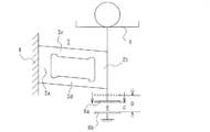
本発明の第1の実施形態の計量器は、図4に示すように、変位体、例えばロバーバル弾性体2を有している。このロバーバル弾性体2は、互いに平行な固定部2aと荷重負荷部2bと、これら固定部2a及び荷重負荷部2bと垂直で互いに平行な変位部2c、2dを有している。固定部2aは、固定基盤4に固定され、荷重負荷部2bには荷重受け皿6が取り付けられている。荷重負荷部2bは、可変コンデンサ8の可動電極8aに結合されている。可変コンデンサ8は固定電極8bも有している。固定電極8bは、可動電極8aと同じ面積を持ち、可動電極8aと平行に位置している。受け皿6に物品が載荷されていない状態で、可動電極8aと固定電極8bとは予め定めた距離Dを有し、物品が載荷されて変位部2c、2dが例えば下方に変位することにより、可動電極8aと固定電極8bとの距離dが変化し、例えば狭くなり、コンデンサ8の静電容量が変化し、例えば、非載荷時の静電容量より大きくなる。
As shown in FIG. 4, the measuring instrument according to the first embodiment of the present invention includes a displacement body, for example, a rubber
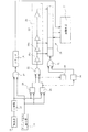
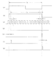
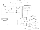
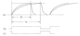
このように物品の載荷によって容量が変化する可変コンデンサ8は、図1に示すように電気回路、例えば発振回路10の一部を構成している。この発振回路10は、発振信号を発振する。この発振回路10では、荷重受け皿6に物品が載荷されていない状態での発振周波数(基準発振周波数f0、基準周期T0)が例えば0.5KHz(2m秒)に設定され、荷重受け皿6に物品が載荷されると、発振周波数が低くなる(発振周期が長くなる)。例えば定格の物品が荷重受け皿6に載荷されると、発振周波数は0.4KHzに変化する。即ち、発振信号の1周期が時間信号の長さであり、これは載荷された物品の重量に応じて変化する。図2(a)に、定格物品が載荷された状態での発振回路10の発振信号を示す。この発振信号は、第1のレベル、例えばHレベルを維持し、その後に第2のレベル、例えばLレベルに変化し、このHレベルとLレベルとの期間を1周期として、繰り返すものである。同図(a)におけるTxは、定格物品が載荷された状態での1周期(2.5m秒)を示す。
As described above, the
この発振回路10の発振信号は、分周手段、例えば分周器12に供給され、例えば2分周される。この分周信号を図2(b)に示す。この分周信号は、発振信号がHレベルに立ち上がった時点(1周期の始点)に、第1のレベル、例えばHレベルに変化し、1周期が終了した時点(発振信号がHレベルからLレベルに変化し、再びHレベルに立ち上がったとき)、第2のレベル、例えばLレベルとなる。
The oscillation signal of the
また、この計量器は、図1に示すように、クロック信号発生器14も設けられている。クロック信号発生器14は、図2(c)に示すように、発振信号の基準周波数よりも高い周波数、例えば4MHzのクロック信号を発生する。クロック周波数は、上記定格の物品が載荷されたときの発振周波数(0.4KHz)の10000倍である。従って、このクロック信号を用いて、定格物品が載荷されているときの発振信号の周波数を測定すると、分解能は1/10000となる。
As shown in FIG. 1, this measuring instrument is also provided with a
分周器12からの分周信号とクロック信号とは、ゲート手段、例えばアンドゲート16を介して計数手段、例えばカウンタ18の入力端子に供給される。分周信号がHレベルになった以後に始めてクロック信号が立ち上がると、カウンタ18のカウント値が初期値0から1となり、その後クロック信号が立ち上がるごとに、カウンタ18がカウント値を1つずつ増加する。このカウントは、分周信号がLレベルとなると中止される。即ち、発振信号の1周期の始点以後、最初に発生したクロック信号から、発振信号の1周期の終点の直前に発生したクロック信号までがカウントされる。例えば図2(b)に示す期間Ty中に発生したクロック信号の数がカウントされる。このカウント値は、例えばCPUによって構成されている演算手段、例えば演算制御部21に供給される。
The frequency-divided signal and the clock signal from the
分周器12からの分周信号の立ち上がり、即ち分周信号がHレベルになった時点(発振信号の1周期の始点)から周期Tyの始点までの期間taと、周期Tyの終点から分周信号の立下り、即ち分周信号がLレベルに変化する時点(発振信号の1周期の終点)までの期間tcとが測定できれば、ta+Ty+tcの演算によって、発振信号の1周期の期間Txを求めることができる。分周信号がHレベルになったときから、その後に始めてクロック信号が立ち上がるまでの期間を測定することによって、期間taを測定することができる。一方、期間tcの測定をいつから開始すればよいか、即ち分周信号がLレベルに変化する時点(発振信号の1周期の終点)がいつであるか不定であるので、期間tcを直接に測定することは不可能である。そこで、分周信号がたち下がった時点、即ち発振信号の1周期の終点から、その後に初めてクロック信号が立ち上がったときまでの期間tbを測定する。これの始点及び終点は、分周信号の立ち下がり及びクロック信号の立ち上がりによって特定することができる。また、周期Tyの終点は、分周信号が立ち下がる直前にクロック信号が立ち上がった時点であり、この時点から周期tbの終点の時点までの期間は、クロック信号の1周期Tcである。そこで、Tc−tbの演算を行うことによってtcを求めることができる。
Rise of the frequency-divided signal from the
これらta、tbの測定を高精度に行うために、時間デジタル変換方式の測定が行われている。即ち、時間taの期間中、第1のレベル、例えばHレベルを維持する状態変化信号を発生するために、図1に示すようにパルス発生器20が設けられている。パルス発生器20は、分周器12の分周信号が立ち上がったときに出力パルス信号をHレベルとし、それ以後にクロック信号が立ち上がったときに出力パルス信号を第2のレベル、例えばLレベルに変化させる(図2(d)参照)ように構成されている。この出力パルス信号は、オアゲート22を介して測定手段、例えば時間デジタル測定手段、具体的には時間デジタル測定器24の遅延手段、ゲート段26の初段に入力されている。
In order to measure these ta and tb with high accuracy, time digital conversion measurement is performed. That is, a
ゲート段26は、複数のゲート26a、26b・・・・を縦続接続したもので、1段あたりの伝送遅れ時間が、クロック信号の1周期よりも短い、例えばtsピコ秒のものである。そして、この段数は、クロック信号の1周期Tcの長さをtsピコ秒で除算した値よりも幾分大きく選択されている。反対にゲート段数がNのとき、使用されるクロック信号の1周期は、N・tsよりも少し短い値に選択される。
The
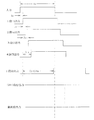
図3に示すように時間信号taが、初段に入力されると、1段目のゲート26aの出力は、tsピコ秒遅れて生じ、2段目の出力は、2tsピコ秒遅れて生じ、以下同様に遅れて生じる。
As shown in FIG. 3, when the time signal ta is input to the first stage, the output of the
各ゲート26a、26b・・・の出力を、各ゲート26a、26b・・・に対応した記憶段28a、28b・・・を持つ記憶手段、例えばメモリ28に入力し、パルス発生器20からの状態変化信号の立下りに応動して立ち上がり所定時間Hレベルを維持する記憶指令信号(図2(e)参照)をパルス信号発生器30に発生させ、オアゲート32を介してメモリ28に供給し、そのときの各ゲートの出力状態を、メモリ28の対応する段に記憶させる。
The outputs of the
ここで、例えば図3に示すように、例えば入力された状態変化信号が立ち下がったときに、最も最終段に近くて、Hレベルを維持している段が、j段の出力であるとすると、taは、(j−1)*ts(ピコ秒)として、決定される。この演算を行うために、メモリ28の各段の出力は、演算制御部21に供給されている。
Here, for example, as shown in FIG. 3, when the input state change signal falls, the stage that is closest to the final stage and maintains the H level is the j-stage output. , Ta is determined as (j−1) * ts (picoseconds). In order to perform this calculation, the output of each stage of the
同様にして期間tbを測定するために、図2(e)に示すように分周信号の立下りに応動してHレベルとなり、それ以後に発生したクロック信号の立ち上がりでLレベルとなる状態変化信号をパルス発生器34に発生させ、このパルス信号発生器34からの状態変化信号の立下りに応動して所定期間Hレベルとなる記憶指令信号をパルス信号発生器36に発生させている。状態変化信号は、オアゲート22を介してゲート段26に供給され、記憶指令信号はオアゲート32を介してメモリ28に供給されている。このように時間デジタル測定器24が第1及び第2の時間デジタル測定手段として機能する。この時間デジタル測定器24を使用することによって、ta、tbをtsピコ秒の分解能で測定することができる。
Similarly, in order to measure the period tb, as shown in FIG. 2 (e), the state changes to the H level in response to the falling edge of the divided signal and to the L level at the rising edge of the clock signal generated thereafter. A signal is generated in the
上述したように、Txは、ta+Ty+Tc−tbの演算によって求めることができ、Ty、Tcとta、tbは連続しているので、結局、Txは、tsピコ秒のという高分解能で測定することができる。1/T0−1/Txの演算を演算制御部21によって行えば、荷重受け皿6に載荷された物品の重量Wを算出することができる。例えばts=50ピコ秒とすると、発振周期の変化分0.5m秒(2.5ミリ秒−2.0ミリ秒)を50ピコ秒の分解能で測定しているので、500*106/50=107、即ち1/107の分解能で発振周波数の周期を測定することが可能になり、これを重量信号に変換すれば高い分解能で重量値を得ることができる。
As described above, Tx can be obtained by calculating ta + Ty + Tc− tb. Since Ty, Tc and ta, tb are continuous, Tx should be measured with a high resolution of ts picoseconds. Can do. If the
第2の実施形態の計量器を図5及び図6に示す。この実施形態の計量器は、図5に示すように、第1の実施形態の計量器において使用したのと同様にロバーバル弾性体に設けた可変コンデンサ8と、固定抵抗器40とを直列に接続した充放電回路を有している。この充放電回路に直列に充電用スイッチ42を介して直流電源(図示せず)から一定、例えば+Vの直通電圧が供給されている。ロバーバル弾性体に対して物品が非載荷の状態において固定抵抗器40の両端間電圧が予め定めた電圧に到達する充電時間T0と、ロバーバル弾性体に対して物品が載荷された状態において固定抵抗器40の両端間電圧が上記予め定めた電圧に到達する充電時間Twとは異なり、例えば充電時間Twの方が長くなる(図6(a)参照)。即ち、これら充電時間T0、Twは、荷重に応じて長さが変化する時間信号である。これら両充電時間To、Twを測定し、その差を求めることによって載荷された物品の重量を測定することができる。なお、充電用スイッチ40は、演算制御部21からHレベルの信号が供給されている期間、閉成される。また、充電された可変コンデンサ8を放電するために、固定抵抗器40の両端間に放電用スイッチ44が設けられている。この放電用スイッチ44も演算制御部21からHレベルの信号が供給されている期間、閉成される。
The measuring instrument of 2nd Embodiment is shown in FIG.5 and FIG.6. As shown in FIG. 5, the measuring instrument of this embodiment is connected in series with a
充放電回路の時定数(可変コンデンサ8の容量Cと固定抵抗器の抵抗値Rとによって定まる)に相当する電圧レベルを上記予め定めた電圧etとして基準電源46から比較手段、例えばコンパレータ48に供給し、固定抵抗器40の両端間電圧をコンパレータ48に供給する。可変コンデンサ8が放電している状態において測定が開始され、演算制御部21は図6(b)に示すようにHレベルの信号を充電用スイッチ42に供給し、Lレベルの信号を放電用スイッチ44に供給する。これによって、可変コンデンサ8の充電が開始され、固定抵抗器40の両端間電圧が上昇する。この電圧が予め定めた電圧etに到達したとき、コンパレータ48の出力信号がLレベルからHレベルに変化し、演算制御部21は、同図(c)に示すように充電用スイッチ40にLレベルの信号を供給し、放電用スイッチ44にHレベルの信号を供給する。これによって、コンデンサ8は、放電用スイッチ44を介して急速に放電する。放電用スイッチ40の開閉用信号がHレベルである期間が充電時間を表している。
A voltage level corresponding to the time constant of the charge / discharge circuit (determined by the capacitance C of the
この放電用スイッチ40の開閉用の信号とクロック信号発生器14とのクロック信号が、図1に示したアンドゲート16に供給され、その出力が図1に示したカウンタ18に供給され、図2に示したTyに相当する時間が計測される。放電用スイッチ40の開閉用の信号とクロック信号とが入力され、放電用スイッチの開閉用の信号の立ち上がりに応動してHレベルとなり、それ以後に初めて発生したクロック信号の立ち上がりに応動してLレベルとなる状態変化信号をパルス信号発生器50が発生して、図1に示したゲート段26の初段にオアゲート22を介して供給されている。この状態変化信号の立下りに応動して、所定時間にわたってHレベルを維持する記憶指令信号を、パルス発生器52が発生して、図1に示したオアゲート32を介してメモリ26に供給する。同様に、放電用スイッチ40の開閉用の信号の立下りに応動してHレベルとなり、それ以後に初めて発生したクロック信号の立ち上がりに応動してLレベルとなる状態変化信号をパルス発生器54が発生して、図1に示したゲート段26の初段にオアゲートを介して供給されている。この状態変化信号の立下りに応動して所定時間にわたってHレベルを維持する記憶指令信号を、パルス発生器56が発生して、図1に示したオアゲート32を介してメモリ26に供給する。これによって第1の実施の形態におけるta、tbに対応する期間が時間デジタル方式によって測定され、充電時間T0、Twが、第1の実施の形態におけるTxと同様にして測定される。
A signal for opening / closing the
例えば可変コンデンサ8の初期荷重のみのときの容量が17.86PFであるとすると、第1の実施の形態と同様に定格荷重が印加されたとき、容量は17.86pF*5/4=22.325pFとなる。低消費電力で計量器を動作させるために固定抵抗器40に1Mオームを選択すると、T0は1.786*10−5秒となり、Twは2.2325*10−5秒となり、負荷荷重によって生じる時間差は、4.465*10−6秒となる。To、Twをそれぞれ第1の実施の形態と同様に4MHzのクロック信号を用いて同じ動作を行わせることによって50p秒の分解能で測定すると、時間差を求める分解能は4.465/5*105、即ち約100,000カウントの分解能を持って重量値を測定することができる。
For example, assuming that the capacity of the
上記の両実施形態において、使用されている最高周波数がクロック信号の4MHzであって、発明が解決する課題で述べた20MHzの発振周波数を使用した回路よりも充分に消費電力が少なくなる上に、発振回路や充放電回路に挿入する抵抗値として数10kオーム以上の値が選択可能であるので、計量器の測定回路全体の消費電力を少なくすることができる。また、分解能も上述したように高くすることができる。 In both the above embodiments, the maximum frequency used is 4 MHz of the clock signal, and the power consumption is sufficiently lower than the circuit using the oscillation frequency of 20 MHz described in the problem to be solved by the invention. Since a resistance value of several tens of k ohms or more can be selected as the resistance value to be inserted into the oscillation circuit or the charge / discharge circuit, the power consumption of the entire measuring circuit of the measuring instrument can be reduced. Also, the resolution can be increased as described above.
上記の両実施の形態では、時間デジタル方式によって時間ta、tbを測定した。しかし、ゲート段26の段数をかなり多くする必要があるが、周期Txや充電時間Tw全体を時間デジタル方式によって測定することもできる。なお、上記の実施の形態では、周期Txや充電時間Twの初期及び後期のクロック信号の周期よりも短いわずかな時間ta、tbだけを時間デジタル方式によって測定しているので、ゲート段26の段数を減少させることができる。上記の実施の形態では、変形体としてロバーバル弾性体を用いたが、荷重の印加によって変位するものであれば種々のものを使用することができ、例えば片持ち梁型の変位体を使用することができる。また、上記の実施の形態では、可変コンデンサ8は荷重の印加によって2つの電極8a、8bの間隔が狭まるものを使用したが、逆に2つの電極8a、8bの間隔が広がるものを使用することもできる。上記の実施の形態では、印加された荷重に応じて長さが変化する時間信号を発生する電気回路として、可変コンデンサ8を含む発振回路10または充放電回路を使用したが、これに限ったものではなく、例えば特開昭59−131131号公報に開示されているような荷重に比例した応力、例えば張力を振動体、例えば弦に印加し、この振動体を構成要素の一部とし、与えられた張力の変化に応じて振動周期が変化する発振回路を使用することもできる。なお、振動体としては、弦の他に音叉や水晶振動子を使用することもできるし、また、振動体が張力の他に圧縮力を受けるように構成することもできる。
In both the above embodiments, the times ta and tb are measured by the time digital method. However, although it is necessary to increase the number of stages of the
8 可変コンデンサ
10 発振器
12 分周器
14 クロック信号発生器
18 カウンタ
24 時間デジタル測定器
8
Claims (10)
前記時間信号の始点よりも後で前記時間信号の終点の前後の期間である主期間を測定する主期間測定手段と、
前記時間信号の始点から前記主期間の始点までの測定期間を時間デジタル変換方式で測定する第1の時間デジタル測定手段と、
前記主期間の終点から前記時間信号の終点までの測定期間を時間デジタル変換方式で測定する第2の時間デジタル測定手段と、
前記主期間測定手段、第1及び第2の時間デジタル測定手段の測定値に基づいて前記時間信号の長さを算出する算出手段とを、
具備し、
前記主期間測定手段は、
前記時間信号の長さよりも周期が短いクロック信号をカウントするカウント手段からなり、
前記第1及び第2の時間デジタル測定手段は、
前記測定期間中、レベルが第1の状態を維持し、その後に第2の状態に変化する状態変化信号を発生する信号発生手段と、
前記クロック信号の1周期よりも短い遅延時間をそれぞれが持つ複数の段が初段から最終段まで縦続接続され、前記状態変化信号が入力される遅延段と、
前記状態変化信号が第2の状態に変化したとき、前記各段の出力のうち前記最終段に最も近くて第1の状態を維持している段を検出し、この検出された段と前記初段との間の段数と前記遅延時間とに基づいて前記測定期間を演算する演算手段とを、
具備する計量器。 An electrical circuit for generating a time signal whose length varies according to the applied load;
Main period measuring means for measuring a main period that is a period before and after the end point of the time signal after the start point of the time signal;
First time digital measurement means for measuring a measurement period from a start point of the time signal to a start point of the main period by a time digital conversion method;
Second time digital measurement means for measuring a measurement period from the end point of the main period to the end point of the time signal by a time digital conversion method;
Calculating means for calculating the length of the time signal based on the measurement values of the main period measuring means and the first and second time digital measuring means;
Equipped,
The main period measuring means includes
Comprising a counting means for counting clock signals having a cycle shorter than the length of the time signal,
The first and second time digital measuring means are:
A signal generating means for generating a state change signal that maintains a first state during the measurement period and then changes to a second state;
A plurality of stages each having a delay time shorter than one cycle of the clock signal are cascaded from the first stage to the last stage, and the delay stage to which the state change signal is input;
When the state change signal changes to the second state, the stage that is closest to the final stage and maintains the first state among the outputs of the stages is detected, and the detected stage and the first stage are detected. Calculating means for calculating the measurement period based on the number of stages between and the delay time,
A measuring instrument.
前記時間信号の少なくとも一部を時間デジタル変換方式で測定する測定手段と、
この測定手段の測定値に基づいて前記負荷荷重を算出する負荷荷重算出手段とを、
具備し、前記測定手段は、
前記時間信号の少なくとも一部を測定中、レベルが第1の状態を維持し、その後に第2の状態に変化する状態変化信号を発生する信号発生手段と、
前記時間信号のよりも小さい周期のクロック信号よりも更に小さい遅延時間をそれぞれが持つ複数の段が初段から最終段まで縦続接続され、前記状態変化信号が入力される遅延段と、
前記状態変化信号が第2の状態に変化したとき、前記各段の出力のうち前記最終段に最も近くて第1の状態を維持している段を検出し、この検出された段と前記初段との間の段数と前記遅延時間とに基づいて前記測定期間を演算する演算手段とを、
具備する計量器。 An electric circuit that generates a time signal whose length changes according to the displacement of the displacement body that changes according to the magnitude of the load, and
Measuring means for measuring at least a part of the time signal by a time digital conversion method;
Load load calculating means for calculating the load load based on the measurement value of the measuring means;
Comprising the measuring means,
Signal generating means for generating a state change signal whose level maintains a first state and then changes to a second state during measurement of at least a portion of the time signal;
A plurality of stages each having a delay time smaller than a clock signal having a period smaller than that of the time signal are cascaded from the first stage to the last stage, and the delay stage to which the state change signal is input,
When the state change signal changes to the second state, the stage that is closest to the final stage and maintains the first state among the outputs of the stages is detected, and the detected stage and the first stage are detected. Calculating means for calculating the measurement period based on the number of stages between and the delay time,
A measuring instrument.
Priority Applications (1)
| Application Number | Priority Date | Filing Date | Title |
|---|---|---|---|
| JP2005146502A JP4675673B2 (en) | 2005-05-19 | 2005-05-19 | Meter |
Applications Claiming Priority (1)
| Application Number | Priority Date | Filing Date | Title |
|---|---|---|---|
| JP2005146502A JP4675673B2 (en) | 2005-05-19 | 2005-05-19 | Meter |
Publications (2)
| Publication Number | Publication Date |
|---|---|
| JP2006322814A JP2006322814A (en) | 2006-11-30 |
| JP4675673B2 true JP4675673B2 (en) | 2011-04-27 |
Family
ID=37542608
Family Applications (1)
| Application Number | Title | Priority Date | Filing Date |
|---|---|---|---|
| JP2005146502A Expired - Lifetime JP4675673B2 (en) | 2005-05-19 | 2005-05-19 | Meter |
Country Status (1)
| Country | Link |
|---|---|
| JP (1) | JP4675673B2 (en) |
Families Citing this family (1)
| Publication number | Priority date | Publication date | Assignee | Title |
|---|---|---|---|---|
| CN103356169B (en) | 2007-12-27 | 2015-07-22 | 国立大学法人筑波大学 | Detector for position of gravitational center and wearing-type motion assisting device equipped with detector for position of gravitational center |
Family Cites Families (1)
| Publication number | Priority date | Publication date | Assignee | Title |
|---|---|---|---|---|
| JPH0222525A (en) * | 1988-07-11 | 1990-01-25 | Sanyo Electric Co Ltd | Electronic scale |
-
2005
- 2005-05-19 JP JP2005146502A patent/JP4675673B2/en not_active Expired - Lifetime
Also Published As
| Publication number | Publication date |
|---|---|
| JP2006322814A (en) | 2006-11-30 |
Similar Documents
| Publication | Publication Date | Title |
|---|---|---|
| KR101390274B1 (en) | Integrated time and/or capacitance measurement system, method and apparatus | |
| CN101490567B (en) | Method and device for measuring the capacitance of a capacitive component | |
| CN100576686C (en) | Charge-discharge control circuit and charge-type power supply device | |
| JPWO2006038468A1 (en) | Phase difference measurement circuit | |
| JP2004198393A (en) | Frequency measurement circuit and vibration sensor type differential pressure / pressure transmitter using the same | |
| JPH06242159A (en) | Electrostatic capacity measuring device | |
| US6369563B1 (en) | Method for high resolution measurement of a position | |
| US11333693B2 (en) | Frequency measurement apparatus, microcontroller, and electronic apparatus | |
| US9255950B2 (en) | Method and arrangement for frequency determination | |
| TW201027904A (en) | Single-pin RC oscillator and method thereof and apparatus with single-pin RC oscillator | |
| JP4675673B2 (en) | Meter | |
| KR100632864B1 (en) | Capacitance change detection method and detection integrated circuit | |
| JP2010025667A (en) | Parallel resistance measuring method and device therefor | |
| JP7653830B2 (en) | Semiconductor device and method for monitoring remaining battery charge | |
| JP2010054229A (en) | Capacitance measuring apparatus | |
| KR100653403B1 (en) | Capacitance change detection method and detection integrated circuit | |
| US20030193843A1 (en) | Method for high resolution measurement of a position | |
| CN112986691A (en) | Sensing circuit and method for calculating capacitance value by using sensing circuit with inverter | |
| JP6212256B2 (en) | AD conversion processor | |
| JP5213808B2 (en) | Time measurement circuit | |
| JP2007163237A (en) | Capacitance measuring apparatus and capacitance measuring method | |
| JP5660000B2 (en) | Frequency measuring device | |
| EP0885373B1 (en) | Method for high resolution measurement of a time period | |
| JP3137156B2 (en) | Motor drive | |
| US20110301475A1 (en) | Voltage-frequency conversion circuit and blood pressure measurement device equipped with same |
Legal Events
| Date | Code | Title | Description |
|---|---|---|---|
| A621 | Written request for application examination |
Free format text: JAPANESE INTERMEDIATE CODE: A621 Effective date: 20080428 |
|
| A131 | Notification of reasons for refusal |
Free format text: JAPANESE INTERMEDIATE CODE: A131 Effective date: 20101027 |
|
| A521 | Request for written amendment filed |
Free format text: JAPANESE INTERMEDIATE CODE: A523 Effective date: 20101224 |
|
| TRDD | Decision of grant or rejection written | ||
| A01 | Written decision to grant a patent or to grant a registration (utility model) |
Free format text: JAPANESE INTERMEDIATE CODE: A01 Effective date: 20110125 |
|
| A01 | Written decision to grant a patent or to grant a registration (utility model) |
Free format text: JAPANESE INTERMEDIATE CODE: A01 |
|
| A61 | First payment of annual fees (during grant procedure) |
Free format text: JAPANESE INTERMEDIATE CODE: A61 Effective date: 20110126 |
|
| FPAY | Renewal fee payment (event date is renewal date of database) |
Free format text: PAYMENT UNTIL: 20140204 Year of fee payment: 3 |
|
| R150 | Certificate of patent or registration of utility model |
Ref document number: 4675673 Country of ref document: JP Free format text: JAPANESE INTERMEDIATE CODE: R150 Free format text: JAPANESE INTERMEDIATE CODE: R150 |
|
| R250 | Receipt of annual fees |
Free format text: JAPANESE INTERMEDIATE CODE: R250 |
|
| R250 | Receipt of annual fees |
Free format text: JAPANESE INTERMEDIATE CODE: R250 |
|
| R250 | Receipt of annual fees |
Free format text: JAPANESE INTERMEDIATE CODE: R250 |
|
| R250 | Receipt of annual fees |
Free format text: JAPANESE INTERMEDIATE CODE: R250 |
|
| R250 | Receipt of annual fees |
Free format text: JAPANESE INTERMEDIATE CODE: R250 |
|
| R250 | Receipt of annual fees |
Free format text: JAPANESE INTERMEDIATE CODE: R250 |
|
| R250 | Receipt of annual fees |
Free format text: JAPANESE INTERMEDIATE CODE: R250 |
|
| R250 | Receipt of annual fees |
Free format text: JAPANESE INTERMEDIATE CODE: R250 |
|
| R250 | Receipt of annual fees |
Free format text: JAPANESE INTERMEDIATE CODE: R250 |
|
| R250 | Receipt of annual fees |
Free format text: JAPANESE INTERMEDIATE CODE: R250 |
|
| EXPY | Cancellation because of completion of term |