JP4673776B2 - Key unit - Google Patents

Key unit Download PDF

Info

Publication number
JP4673776B2
JP4673776B2 JP2006079331A JP2006079331A JP4673776B2 JP 4673776 B2 JP4673776 B2 JP 4673776B2 JP 2006079331 A JP2006079331 A JP 2006079331A JP 2006079331 A JP2006079331 A JP 2006079331A JP 4673776 B2 JP4673776 B2 JP 4673776B2
Authority
JP
Japan
Prior art keywords
key
support
spring
case
support shaft
Prior art date
Legal status (The legal status is an assumption and is not a legal conclusion. Google has not performed a legal analysis and makes no representation as to the accuracy of the status listed.)
Expired - Fee Related
Application number
JP2006079331A
Other languages
Japanese (ja)
Other versions
JP2007255014A (en
Inventor
和宏 宮田
幹彦 川瀬
Current Assignee (The listed assignees may be inaccurate. Google has not performed a legal analysis and makes no representation or warranty as to the accuracy of the list.)
Minebea AccessSolutions Inc
Original Assignee
Honda Lock Manufacturing Co Ltd
Priority date (The priority date is an assumption and is not a legal conclusion. Google has not performed a legal analysis and makes no representation as to the accuracy of the date listed.)
Filing date
Publication date
Application filed by Honda Lock Manufacturing Co Ltd filed Critical Honda Lock Manufacturing Co Ltd
Priority to JP2006079331A priority Critical patent/JP4673776B2/en
Priority to US11/712,586 priority patent/US7370501B2/en
Publication of JP2007255014A publication Critical patent/JP2007255014A/en
Application granted granted Critical
Publication of JP4673776B2 publication Critical patent/JP4673776B2/en
Expired - Fee Related legal-status Critical Current
Anticipated expiration legal-status Critical

Links

Images

Description

本発明は、シリンダ錠に差し込み可能なキープレートの一端部に円形の支持孔が設けられるキーヘッドが結合されて成るメカニカルキーと、前記支持孔に嵌合される支軸を有する支持部材ならびに前記キーヘッドを前記支持部材との間に挟んで前記支持部材に締結される挟持部材とを構成要素の一部として有するとともに前記メカニカルキーの全体を格納する格納位置ならびに前記キープレートを突出させる突出位置間で前記メカニカルキーを回動させることを可能として前記キーヘッドを回動可能に支持する把持ケースと、前記キープレートを突出させる側に前記メカニカルキーを付勢する弾発力を発揮するようにして一端が前記キーヘッドに係合されるとともに他端が前記挟持部材に設けられたばね係止部に係合されるねじりばねとを備えるキーユニットに関する。   The present invention relates to a mechanical key formed by coupling a key head provided with a circular support hole at one end of a key plate that can be inserted into a cylinder lock, a support member having a support shaft fitted in the support hole, and the above-mentioned A storage position for storing the whole of the mechanical key and a protruding position for projecting the key plate, as a part of the constituent elements, and a sandwiching member fastened to the support member with the key head sandwiched between the support member A holding case that rotatably supports the key head so that the mechanical key can be rotated, and a resilient force that urges the mechanical key toward the side from which the key plate protrudes. And a torsion spring having one end engaged with the key head and the other end engaged with a spring locking portion provided on the clamping member. That on the key unit.

このようなキーユニットは、たとえば特許文献1で既に知られており、ねじりばねの弾発力でメカニカルキーのキープレートを把持ケースから突出させるようにしている。
特開昭63−110377号公報
Such a key unit is already known from Patent Document 1, for example, and the key plate of the mechanical key is projected from the gripping case by the elastic force of a torsion spring.
JP-A-63-1110377

ところで、メカニカルキーのキーヘッドは、支持部材の支軸で回動可能に支承されるととっもに支持部材ならびに支持部材に締結される挟持部材間に挟まれており、ねじりばねは、キーヘッドおよび挟持部材間に設けられるものであり、挟持部材の支持部材への組付け時には、ねじりばねのばね力に抗して支持部材に締結しなければならない。そのため、組付け作業を熟練者が行うことが必要であったり、特殊な工具を必要としたり、しかも作業工数も多くなっている。   By the way, the key head of the mechanical key is supported between the support member and the clamping member fastened to the support member, and is supported between the support member and the support member. In addition, when the clamping member is assembled to the support member, it must be fastened to the support member against the spring force of the torsion spring. For this reason, it is necessary for an expert to perform the assembly work, special tools are required, and the number of work steps is also increased.

本発明は、かかる事情に鑑みてなされたものであり、特別な工具や熟練作業員であることを不要とした簡単な組付け作業で挟持部材を支持部材に締結可能とし、作業工数の低減も可能としたキーユニットを提供することを目的とする。   The present invention has been made in view of such circumstances, and allows the clamping member to be fastened to the support member by a simple assembling work that does not require special tools or skilled workers, and also reduces the number of work steps. An object is to provide a key unit that is made possible.

上記目的を達成するために、請求項1記載の発明は、シリンダ錠に差し込み可能なキープレートの一端部に円形の支持孔が設けられるキーヘッドが結合されて成るメカニカルキーと、前記支持孔に嵌合される支軸を有する支持部材ならびに前記キーヘッドを前記支持部材との間に挟んで前記支持部材に締結される挟持部材とを構成要素の一部として有するとともに前記メカニカルキーの全体を格納する格納位置ならびに前記キープレートを突出させる突出位置間で前記メカニカルキーを回動させることを可能として前記キーヘッドを支持する把持ケースと、前記キープレートを突出させる側に前記メカニカルキーを付勢する弾発力を発揮するようにして一端が前記キーヘッドに係合されるとともに他端が前記挟持部材に設けられたばね係止部に係合されるねじりばねとを備えるキーユニットにおいて、前記支軸の先端部に嵌合、連結される支持筒部が前記挟持部材に一体に設けられ、前記支軸の周囲には、前記キーヘッドに一端を係合せしめた状態でばね力を発揮しない自然な状態にある前記ねじりばねの他端を前記支持部材と非締結状態にある前記挟持部材の前記ばね係止部に係合させるようにしたばね係合位置と、前記ばね係止部に前記ねじりばねを係合した前記挟持部材を前記ねじりばねに弾発力を発揮させる側に所定量回動させた締結位置とが設定され、前記支軸の軸線まわりに前記ばね係合位置から前記締結位置に回動した前記挟持部材に当接する位置決め規制部が前記支持部材に設けられ、位置決め規制部に当接した状態の前記挟持部材が前記支持部材に締結されることを特徴とする。   In order to achieve the above object, the invention according to claim 1 is characterized in that a mechanical key formed by coupling a key head provided with a circular support hole at one end of a key plate which can be inserted into a cylinder lock, and the support hole A support member having a support shaft to be fitted and a clamping member fastened to the support member with the key head sandwiched between the support member and the mechanical key as a whole are stored. A holding case for supporting the key head by allowing the mechanical key to be rotated between a storing position for the key plate and a protruding position for protruding the key plate; and biasing the mechanical key to the side on which the key plate protrudes A spring locking portion having one end engaged with the key head so as to exert a resilient force and the other end provided on the clamping member In the key unit including the torsion spring to be engaged, a support cylinder portion that is fitted to and connected to the distal end portion of the support shaft is provided integrally with the clamping member, and the key head is provided around the support shaft. The other end of the torsion spring in a natural state in which the spring force is not exerted with one end engaged with the support member is engaged with the spring locking portion of the clamping member that is not fastened with the support member. A spring engagement position and a fastening position in which the clamping member engaged with the torsion spring in the spring engaging portion is rotated by a predetermined amount to the side that exerts a resilient force on the torsion spring is set. A positioning restriction portion that contacts the holding member rotated from the spring engagement position to the fastening position around the axis of the support shaft is provided on the support member, and the holding member in a state of contact with the positioning restriction portion is the Fastened to the support member The features.

また請求項2記載の発明は、請求項1記載の発明の構成に加えて、前記支持部材および前記挟持部材には、前記支持部材から離反する側に前記挟持部材を付勢するばね力を前記挟持部材が前記締結位置にある状態では相互に圧接する方向で受けるようにして当接する当接面が、前記支軸の軸線に直交する平面に沿うようにしてそれぞれ形成されることを特徴とする。   According to a second aspect of the invention, in addition to the configuration of the first aspect of the invention, the support member and the holding member have a spring force for urging the holding member toward the side away from the support member. In the state in which the clamping member is in the fastening position, contact surfaces that contact each other so as to be received in a direction in which they are pressed against each other are formed along a plane perpendicular to the axis of the support shaft, respectively. .

なお実施例のロアケース27が本発明の支持部材に対応し、実施例のアッパケース28が本発明の挟持部材に対応する。   The lower case 27 of the embodiment corresponds to the support member of the present invention, and the upper case 28 of the embodiment corresponds to the clamping member of the present invention.

請求項1記載の発明によれば、支持部材の支軸をキーヘッドの支持孔に嵌合し、一端をキーヘッドに係合せしめて自然な状態にあるねじりばねの他端を、前記支軸の先端部に支持筒部を嵌合、連結した状態でばね係合位置に配置した挟持部材のばね係止部に係合し、挟持部材をばね係合位置からねじりばねが弾発力を発揮する側に捩じるようにして支軸のまわりに回動操作して位置決め規制部に当接させると、支持部材が締結位置に達するとともにねじりばねが所定の弾発力を発揮するように捩じられることになり、この状態で挟持部材を支持部材に締結することができるので、特別な工具や熟練作業員であることを不要とした簡単な組付け作業で挟持部材を支持部材に締結することができ、作業工数の低減も可能となる。   According to the first aspect of the present invention, the support shaft of the support member is fitted into the support hole of the key head, and the other end of the torsion spring in a natural state is engaged with the key head. The support cylinder is fitted and connected to the tip, and is engaged with the spring engaging portion of the holding member disposed at the spring engaging position, and the torsion spring exerts the elastic force from the spring engaging position. If the support member reaches the fastening position and is twisted so that the torsion spring exerts a predetermined elastic force when it is rotated around the support shaft and brought into contact with the positioning restricting portion. Since the clamping member can be fastened to the support member in this state, the clamping member can be fastened to the support member by a simple assembling work that does not require special tools or skilled workers. It is possible to reduce the number of work steps.

また請求項2記載の発明によれば、位置決め規制部に当接するまで挟持部材を回動すると、挟持部材に作用しているばね力で支持部材および挟持部材の当接面が相互に圧接することになり、当接面相互の圧接による摩擦力で挟持部材から手を離しても挟持部材が締結位置からばね係合位置側に戻ってしまうことがなく、したがって組付け作業がより容易となる。   According to the second aspect of the present invention, when the holding member is rotated until it comes into contact with the positioning restricting portion, the contact surfaces of the support member and the holding member are pressed against each other by the spring force acting on the holding member. Therefore, even if the hand is released from the pinching member due to the frictional force generated by the pressure contact between the contact surfaces, the pinching member does not return from the fastening position to the spring engagement position side, and therefore the assembling work becomes easier.

以下、本発明の実施の形態を、添付の図面に示した本発明の一実施例に基づいて説明する。   DESCRIPTION OF THE PREFERRED EMBODIMENTS Embodiments of the present invention will be described below based on one embodiment of the present invention shown in the accompanying drawings.

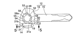
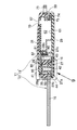
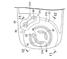
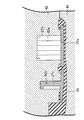
図1〜図20は本発明の一実施例を示すものであり、図1はメカニカルキーが突出位置にある状態でのキーユニットの側面図、図2はメカニカルキーが格納位置にある状態でのキーユニットの側面図、図3は図2の3矢視図、図4はメカニカルキーを図1とは反対側から見た側面図、図5は図4の5−5線断面図、図6はメカニカルキーをシリンダ錠に差し込んだ状態を示す縦断側面図、図7はキーユニットの分解斜視図、図8は図1の8−8線断面図、図9は図8の9矢示部拡大図、図10はロアケースがインサート結合された状態のモジュールケースの一部を示す側面図、図11はモジュールケースの金型成形時の状態を図10の11−11線に沿って示す断面図、図12はモジュールケースの金型成形時の状態を図10の12−12線に沿って示す断面図、図13はアッパケースの斜視図、図14は支軸にメカニカルキーを回動可能に支持した状態を示す側面図、図15は図9の15−15線断面図、図16は図15の16−16線断面図、図17はアッパケースがばね係合位置にある状態を示す側面図、図18は締結位置に回動したアッパケースをロアケースに締結した状態での図17に対応した一部切欠き側面図、図19は図18の19−19線断面図、図20は図1の20−20線断面図である。   1 to 20 show an embodiment of the present invention. FIG. 1 is a side view of a key unit in a state where the mechanical key is in the protruding position, and FIG. 2 is a state in which the mechanical key is in the retracted position. 3 is a side view of the key unit, FIG. 3 is a view as seen from the direction of the arrow 3 in FIG. 2, FIG. 4 is a side view of the mechanical key as viewed from the side opposite to FIG. Is a longitudinal side view showing a state in which the mechanical key is inserted into the cylinder lock, FIG. 7 is an exploded perspective view of the key unit, FIG. 8 is a sectional view taken along line 8-8 in FIG. 1, and FIG. FIG. 10 is a side view showing a part of the module case in a state where the lower case is insert-joined, and FIG. 11 is a cross-sectional view showing a state of the module case during molding along the line 11-11 in FIG. FIG. 12 shows the state of the module case during molding, taken along line 12-12 in FIG. 13 is a perspective view of the upper case, FIG. 14 is a side view showing a state in which the mechanical key is rotatably supported on the support shaft, and FIG. 15 is a sectional view taken along line 15-15 in FIG. 16 is a cross-sectional view taken along line 16-16 in FIG. 15, FIG. 17 is a side view showing a state where the upper case is in the spring engagement position, and FIG. 18 is a view in a state where the upper case rotated to the fastening position is fastened to the lower case. FIG. 19 is a sectional view taken along line 19-19 of FIG. 18, and FIG. 20 is a sectional view taken along line 20-20 of FIG.

先ず図1〜図3において、このキーユニット11は、メカニカルキー12と、該メカニカルキー12の全体を格納する格納位置ならびにメカニカルキー12の一部を突出させる突出位置間での回動を可能としてメカニカルキー12を支持する把持ケース13とを備える。   First, in FIGS. 1 to 3, the key unit 11 can be rotated between a mechanical key 12, a storage position for storing the entire mechanical key 12, and a protruding position for projecting a part of the mechanical key 12. A gripping case 13 that supports the mechanical key 12 is provided.

図4および図5において、メカニカルキー12は、金属製のキープレート15と、該キープレート15の一端に結合されるキーヘッド16とから成り、キーヘッド16はキープレート15の一端をインサート結合するようにして合成樹脂により形成される。しかもキーヘッド16には、キープレート15の長手方向と平行に長く延びる矩形状の収容凹部17がキーヘッド16の一側面に開口するようにして設けられる。また収容凹部17の長手方向両端の幅方向一端側に連なる凹部19,19が収容凹部17よりも浅くしてキーヘッド16に設けられる。   4 and 5, the mechanical key 12 includes a metal key plate 15 and a key head 16 coupled to one end of the key plate 15, and the key head 16 insert-connects one end of the key plate 15. In this way, it is formed of a synthetic resin. Moreover, the key head 16 is provided with a rectangular accommodating recess 17 extending long in parallel with the longitudinal direction of the key plate 15 so as to open on one side of the key head 16. Further, recesses 19, 19 connected to one end in the width direction at both longitudinal ends of the housing recess 17 are provided in the key head 16 so as to be shallower than the housing recess 17.

前記収容凹部17にはトランスポンダー14が収容されるものであり、収容凹部17内のトランスポンダー14を保持するようにしてキーヘッド16に蓋部材21が接着される。而して蓋部材21は、収容凹部17を覆う蓋部21aと、前記凹部19…にそれぞれ嵌合するようにして前記蓋部21aに連なる一対の突部21b,21bとを一体に有するものである。   The accommodating recess 17 accommodates the transponder 14, and the lid member 21 is bonded to the key head 16 so as to hold the transponder 14 in the accommodating recess 17. Thus, the lid member 21 integrally includes a lid portion 21a that covers the housing concave portion 17, and a pair of protrusions 21b and 21b that are continuous with the lid portion 21a so as to be fitted in the concave portions 19. is there.

ところで、メカニカルキー12のキーヘッド16は、メカニカルキー12の全体を格納する格納位置(図2および図3で示す位置)と、メカニカルキー12のうちキープレート15を突出させる突出位置(図1で示す位置)との間で回動するようにして前記把持ケース13に支持されるものであり、把持ケース13から突出した状態にあるキープレート15は、図6で示すように、車両の操向ハンドルのロックおよびロック解除を切換えるとともにエンジンのオン・オフを切換えるシリンダ錠24のキー孔25に挿入される。而してキープレート15のキー孔25への挿入時に、前記シリンダ錠24の前端に設けられるコイル26からの電磁力を受けてトランスポンダー14が特定のID信号を発信し、そのIDコードが予め設定されているIDコードと一致したことをシリンダ錠24側で確認するのに応じて、キーユニット11によるエンジン始動が可能となる。   By the way, the key head 16 of the mechanical key 12 has a storage position (the position shown in FIGS. 2 and 3) for storing the entire mechanical key 12, and a protruding position (in FIG. The key plate 15 that is supported by the gripping case 13 so as to be pivoted between the gripping case 13 and projecting from the gripping case 13 is shown in FIG. It is inserted into the key hole 25 of the cylinder lock 24 that switches between locking and unlocking the handle and switching the engine on and off. Thus, when the key plate 15 is inserted into the key hole 25, the transponder 14 transmits a specific ID signal in response to the electromagnetic force from the coil 26 provided at the front end of the cylinder lock 24, and the ID code is preset. The key unit 11 can start the engine in accordance with confirmation on the cylinder lock 24 side that the ID code matches.

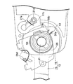
図7〜図9を併せて参照して、把持ケース13は、金属たとえば亜鉛合金等の軽金属から成るロアケース27と、金属たとえば亜鉛合金等の軽金属により形成されて前記ロアケース27にねじ部材32,32で結合されるアッパケース28と、前記ロアケース27の一部を一端部にインサート結合せしめて合成樹脂により形成されるモジュールケース29と、前記アッパケース28を覆ってモジュールケース29に超音波溶着される合成樹脂製のカバー30と、該カバー30および前記モジュールケース29に弾発係合されるとともにモジュールケース29にねじ部材33で締結される合成樹脂製のモジュールカバー31とを備える。   Referring also to FIGS. 7 to 9, the gripping case 13 is formed of a lower case 27 made of a light metal such as a metal such as a zinc alloy and a light metal such as a metal such as a zinc alloy. The upper case 28 to be joined in the above, the module case 29 formed of synthetic resin by insert-joining a part of the lower case 27 to one end portion, and the module case 29 being ultrasonically welded so as to cover the upper case 28. A cover 30 made of synthetic resin and a module cover 31 made of synthetic resin that is elastically engaged with the cover 30 and the module case 29 and fastened to the module case 29 with a screw member 33 are provided.

図10を併せて参照して、ロアケース27は、平板状の基板27aと、該基板27aに直角に連設されてアッパケース28側に突出する円筒状の支軸27bと、円弧状の断面形状を有して支軸27bの一部を囲む連結壁部27cとを一体に有し、前記基板27aがモジュールケース29の内面側にインサート結合される。   Referring also to FIG. 10, the lower case 27 includes a flat board 27 a, a cylindrical support shaft 27 b that is connected to the board 27 a at a right angle and protrudes toward the upper case 28, and an arc-shaped cross-sectional shape. And a connecting wall portion 27c surrounding a part of the support shaft 27b, and the substrate 27a is insert-coupled to the inner surface side of the module case 29.

ところで、前記モジュールケース29の金型成形にあたっては、図11および図12で示すように、モジュールケース29の外面側を成形する第1の金型81と、モジュールケース29の内面側を成形するとともに前記ロアケース27の基板27aに当接するようにして第1の金型81に対して近接、離反可能な第2の金型82とが用いられるのであるが、第2の金型82には、前記支軸27bの軸線に直交する方向での前記ロアケース27の位置を定めるべく、前記支軸27bおよび前記連結壁部27cを嵌合せしめる嵌合凹部82a,82bが設けられる。   By the way, in the mold forming of the module case 29, as shown in FIGS. 11 and 12, the first mold 81 for forming the outer surface side of the module case 29 and the inner surface side of the module case 29 are formed. A second mold 82 that can be moved close to and away from the first mold 81 so as to contact the substrate 27a of the lower case 27 is used. In order to determine the position of the lower case 27 in a direction perpendicular to the axis of the support shaft 27b, fitting recesses 82a and 82b for fitting the support shaft 27b and the connecting wall portion 27c are provided.

しかも第2金型82には、前記支軸27bに設けられた係合孔83に係合して当該支軸27bの軸方向に沿うロアケース27の位置を定めるスライド金型84が、前記支軸27bの半径方向に移動することを可能として配設される。   In addition, the second mold 82 includes a slide mold 84 that engages with an engagement hole 83 provided in the support shaft 27b to determine the position of the lower case 27 along the axial direction of the support shaft 27b. 27b can be moved in the radial direction.

図13を併せて参照して、アッパケース28には、ロアケース27側に突出して前記支軸27bの先端部に嵌合する支持筒部28aと、円弧状の断面形状を有して支持筒部28aの一部を囲む連結壁部28bとが一体に設けられる。   Referring also to FIG. 13, the upper case 28 has a support tube portion 28 a that protrudes toward the lower case 27 and fits to the tip end portion of the support shaft 27 b, and a support tube portion that has an arcuate cross-sectional shape. A connecting wall portion 28b surrounding a part of 28a is integrally provided.

而して前記支軸27bの先端部に支持筒部28aを嵌合するとともに連結壁部27c,28bを相互に当接させた状態で、アッパケース28はロアケース27の連結壁部27cにねじ部材32…で締結される。   Thus, the upper case 28 is screwed to the connecting wall portion 27c of the lower case 27 in a state in which the support cylinder portion 28a is fitted to the tip end portion of the support shaft 27b and the connecting wall portions 27c and 28b are in contact with each other. 32...

相互に嵌合、連結される支軸27bおよび支持筒部28aは、メカニカルキー12におけるキーヘッド16の中央部に設けられた支持孔48を貫通するものであり、ロアケース27およびアッパケース28間に挟まれる前記キーヘッド16は、連結状態にある連結壁部27c,28bの内方で支軸27bおよび支持筒部28aの軸線まわりに回動する。   The support shaft 27 b and the support cylinder portion 28 a that are fitted and connected to each other pass through a support hole 48 provided in the center portion of the key head 16 in the mechanical key 12, and between the lower case 27 and the upper case 28. The key head 16 to be sandwiched rotates around the axes of the support shaft 27b and the support cylinder portion 28a inside the connection wall portions 27c and 28b in a connected state.

またカバー30には、アッパケース28における支持筒部28aの上端開口部に対応した窓35が設けられており、カバー30は、前記モジュールケース29に対して位置決めされた状態で該モジュールケース29に超音波溶着される。   Further, the cover 30 is provided with a window 35 corresponding to the upper end opening of the support cylinder portion 28 a in the upper case 28, and the cover 30 is positioned in the module case 29 while being positioned with respect to the module case 29. Ultrasonic welding.

前記モジュールケース29の一端部およびカバー30間には、メカニカルキー12のキープレート15を突出させるための開口部39がメカニカルキー12の格納位置では前記キーヘッド16の外周の一部を臨ませるようにして形成されており、メカニカルキー12を把持ケース13内に格納すべく把持ケース13の側部に開放して前記開口部39に連なるスリット状の開口部40が、前記モジュールケース29、前記カバー30および前記モジュールカバー31によって形成される。   Between the one end of the module case 29 and the cover 30, an opening 39 for projecting the key plate 15 of the mechanical key 12 faces a part of the outer periphery of the key head 16 when the mechanical key 12 is stored. In order to store the mechanical key 12 in the gripping case 13, a slit-like opening 40 that opens to the side of the gripping case 13 and continues to the opening 39 is formed in the module case 29, the cover 30 and the module cover 31.

支軸27bおよび支持筒部28a内には、上端の半球状閉塞部を前記窓35に臨ませるようにして有底円筒状に形成されるリリースボタン41が上下動を可能として挿入されており、ロアケース27およびリリースボタン41間には、リリースボタン41を上方すなわちロアケース27から離反させる側に付勢するコイルばね42が縮設される。   A release button 41 formed in a bottomed cylindrical shape is inserted into the support shaft 27b and the support cylinder portion 28a so that the upper hemispherical closed portion faces the window 35 so as to be movable up and down. Between the lower case 27 and the release button 41, a coil spring 42 that biases the release button 41 upward, that is, the side that separates the release button 41 from the lower case 27 is provided in a compressed manner.

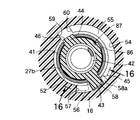
図14を併せて参照して、ロアケース27側でリリースボタン41の外周には、その一直径線に沿って外側方に突出する第1および第2規制突部43,44が一体に突設される。またロアケース27の支軸27bには、軸方向にスリット状に延びる第1および第2規制孔45,46が設けられており、それらの規制孔45,46に前記両規制突部43,44を嵌合せしめることにより、支軸27bおよび支持筒部28a内に挿入されたリリースボタン41が制限された範囲で軸方向に移動することが許容されるとともに、支軸27bおよび支持筒部28a内でのリリースボタン41の回転が阻止される。   Referring also to FIG. 14, first and second restricting protrusions 43 and 44 projecting outward along the one diameter line are integrally provided on the outer periphery of the release button 41 on the lower case 27 side. The Further, the support shaft 27b of the lower case 27 is provided with first and second restricting holes 45 and 46 extending in a slit shape in the axial direction, and the restricting protrusions 43 and 44 are provided in the restricting holes 45 and 46, respectively. By fitting, the support button 27b and the release button 41 inserted into the support tube portion 28a are allowed to move in the axial direction within a limited range, and within the support shaft 27b and the support tube portion 28a. The release button 41 is prevented from rotating.

また前記両規制突部43,44間でリリースボタン41の外周には位置決め突部86が突設されており、前記支軸27bの内周には位置決め突部86をスライド可能に嵌合せしめる嵌合溝87が軸方向に延びるようにして設けられる。而して位置決め突部86の嵌合溝87への嵌合により、支軸27bの軸線まわりでの支軸27bおよびリリースボタン41の相対位置が一定に定めることになる。   A positioning protrusion 86 is provided on the outer periphery of the release button 41 between the restricting protrusions 43 and 44, and the positioning protrusion 86 is slidably fitted on the inner periphery of the support shaft 27b. A joint groove 87 is provided so as to extend in the axial direction. Thus, by fitting the positioning protrusion 86 into the fitting groove 87, the relative position of the support shaft 27b and the release button 41 around the axis of the support shaft 27b is fixed.

前記メカニカルキー12におけるキーヘッド16の中央部には、支軸27bを嵌合せしめる支持孔48が設けられるとともに、支軸27bの先端部および支持筒部28aを囲繞してアッパケース28側の側面に一端を開口するばね収容孔47が、支持孔48よりも大径にして前記支持孔48の一端に同軸に連なるようにして設けられ、ばね収容孔47および支持孔48間にはアッパケース28側に臨む環状の段部49が形成される。   A support hole 48 into which the support shaft 27b is fitted is provided at the center of the key head 16 in the mechanical key 12, and the side surface on the upper case 28 side surrounding the tip end portion of the support shaft 27b and the support cylinder portion 28a. A spring accommodating hole 47 having an opening at one end is provided with a diameter larger than that of the support hole 48 so as to be coaxially connected to one end of the support hole 48. An annular step 49 facing the side is formed.

前記段部49およびアッパケース28間には、支軸27bおよび支持筒部28aを囲繞するねじりばね50が、ばね収容孔47に収容されるようにして配置されており、該ねじりばね50の両端はアッパケース28およびキーヘッド16に係合される。而してこのねじりばね50は、キーヘッド16すなわちメカニカルキー12を、格納位置から突出位置に回動する方向に付勢するばね力を発揮する。   Between the step portion 49 and the upper case 28, a torsion spring 50 surrounding the support shaft 27b and the support cylinder portion 28a is disposed so as to be accommodated in the spring accommodating hole 47, and both ends of the torsion spring 50 are arranged. Is engaged with the upper case 28 and the key head 16. Thus, the torsion spring 50 exerts a spring force that urges the key head 16, that is, the mechanical key 12 in the direction of rotating from the retracted position to the protruding position.

而してねじりばね50の一端に設けられる係合部50aは、図14で明示するように、前記ばね収容孔47の内面に開口するようにして前記キーヘッド16のアッパケース28側に臨む面に設けられる係止孔51に係合される。また図7および図13で示すように、アッパケース28には、前記ねじりばね50の他端に設けられる係合部50bを係合させる溝状のばね係止部28cが設けられる。   Thus, the engaging portion 50a provided at one end of the torsion spring 50 is a surface facing the upper case 28 side of the key head 16 so as to open to the inner surface of the spring accommodating hole 47 as clearly shown in FIG. Is engaged with a locking hole 51 provided in the. As shown in FIGS. 7 and 13, the upper case 28 is provided with a groove-like spring locking portion 28 c that engages an engaging portion 50 b provided at the other end of the torsion spring 50.

図15を併せて参照して、前記キーヘッド16には、前記支持孔48の他端に一端を同軸に連ならせて支持孔48よりも大径に形成される挿入孔52が、第1および第2規制突部43,44を当接させ得る環状の段部53を前記支持孔48との間に形成するとともに支軸27bを囲むようにして同軸に設けられ、挿入孔52の他端はキーヘッド16のアッパケース28とは反対側の側面に開口する。またメカニカルキー12が格納位置および突出位置間で回動する際に、支軸27bから先端部を突出させた第1規制突部43がキーヘッド16に対して相対回動することを許容するための円弧状の案内凹部54が、前記挿入孔52の内周の一部を拡径方向に拡大するようにしてキーヘッド16に設けられており、前記挿入孔52および案内凹部54間には、第1規制突部43を摺接させる円弧状の摺接段部55が形成される。   Referring also to FIG. 15, the key head 16 has a first insertion hole 52 having a diameter larger than that of the support hole 48 with one end connected to the other end of the support hole 48 coaxially. An annular stepped portion 53 capable of contacting the second restricting projections 43 and 44 is formed between the support hole 48 and coaxially so as to surround the support shaft 27b. The other end of the insertion hole 52 is a key. The head 16 opens on the side surface opposite to the upper case 28. Further, when the mechanical key 12 is rotated between the retracted position and the protruding position, the first regulating protrusion 43 having the tip protruding from the support shaft 27b is allowed to rotate relative to the key head 16. Is formed in the key head 16 so as to expand a part of the inner periphery of the insertion hole 52 in the diameter-enlarging direction, and between the insertion hole 52 and the guide recess 54, An arcuate slidable contact step portion 55 is formed to slidably contact the first restricting protrusion 43.

しかも案内凹部54の周方向一端は、支軸27bの外周の第1規制孔45に隣接した位置に突設される突部56を当接させる第1規制面57として形成されるものであり、突出位置側にねじりばね50で付勢されるメカニカルキー12の突出位置側への回動端は前記第1規制面57を支軸27bの突部56に当接させることによって規制される。また図16で示すように、前記第1規制面57の近傍で摺接段部55には、第1規制突部43を嵌合せしめる第1嵌合凹部58が設けられており、第1規制面57を支軸27bの突部56に当接させてメカニカルキー12が突出位置にある状態でリリースボタン41に外力を作用させない自然な状態としたときには、コイルばね42で付勢されているリリースボタン41の第1規制突部43が第1嵌合凹部58に嵌合し、それにより突出位置でのメカニカルキー12の姿勢が保持される。しかも第1嵌合凹部58の周方向両端壁のうち第1規制面57とは反対側の端壁はカム面58aとして機能するように傾斜して形成される。   In addition, one end in the circumferential direction of the guide recess 54 is formed as a first restriction surface 57 that abuts the protrusion 56 that protrudes at a position adjacent to the first restriction hole 45 on the outer periphery of the support shaft 27b. The rotation end of the mechanical key 12 that is biased by the torsion spring 50 toward the protruding position side toward the protruding position side is regulated by bringing the first regulating surface 57 into contact with the protruding portion 56 of the support shaft 27b. As shown in FIG. 16, the sliding contact step 55 near the first restricting surface 57 is provided with a first fitting recess 58 for fitting the first restricting protrusion 43, and the first restricting step 57. When the surface 57 is brought into contact with the projecting portion 56 of the support shaft 27b and the mechanical key 12 is in the projecting position so that an external force is not applied to the release button 41, the release biased by the coil spring 42 is applied. The first restricting protrusion 43 of the button 41 is fitted into the first fitting recess 58, whereby the posture of the mechanical key 12 at the protruding position is maintained. In addition, the end wall on the opposite side of the first restricting surface 57 among the both end walls in the circumferential direction of the first fitting recess 58 is formed to be inclined so as to function as the cam surface 58a.

また前記案内凹部54の周方向他端は、メカニカルキー12の格納位置で第1規制突部43が当接する第2規制面59として形成されるものであり、第2規制面59に当接した第1規制突部43を嵌合させる第2嵌合凹部60が摺接段部55の周方向他端に設けられる。すなわち第2規制面57を第1規制突部43に当接させてメカニカルキー12が格納位置にある状態でリリースボタン41に外力を作用させない自然な状態としたときには、コイルばね42で付勢されているリリースボタン41の第1規制突部43が第2嵌合凹部60に嵌合し、それにより格納位置でのメカニカルキー12の姿勢が保持される。   The other circumferential end of the guide recess 54 is formed as a second restriction surface 59 with which the first restriction projection 43 abuts at the storage position of the mechanical key 12, and abuts against the second restriction surface 59. A second fitting recess 60 for fitting the first restricting protrusion 43 is provided at the other circumferential end of the sliding contact step portion 55. That is, when the second restricting surface 57 is brought into contact with the first restricting protrusion 43 and the mechanical key 12 is in the retracted position so that an external force is not applied to the release button 41, the second restricting surface 57 is biased by the coil spring 42. The first restricting projection 43 of the release button 41 is fitted into the second fitting recess 60, whereby the posture of the mechanical key 12 at the retracted position is maintained.

而してメカニカルキー12を格納位置から突出位置側に回動するときには、窓35に臨むリリースボタン41をコイルばね42のばね力に抗して押し込んだ後に手を放せばよく、そうすれば第2嵌合凹部60から離脱した第1規制突部43を摺接段部55に摺接させながらメカニカルキー12のキーヘッド16がねじりばね50のばね力によって突出位置側に自動的に回動することになり、突出位置ではリリースボタン41が第1規制突部43を第1嵌合凹部58に嵌合するようにコイルばね42で押し出され、第1規制突部43の第1嵌合凹部58への嵌合により、メカニカルキー12の突出位置での姿勢が保持されることになる。   Thus, when the mechanical key 12 is rotated from the retracted position to the projecting position side, the release button 41 facing the window 35 may be released against the spring force of the coil spring 42 and then released. The key head 16 of the mechanical key 12 is automatically rotated to the protruding position side by the spring force of the torsion spring 50 while the first restricting protrusion 43 separated from the fitting recess 60 is in sliding contact with the sliding contact step 55. Thus, at the projecting position, the release button 41 is pushed out by the coil spring 42 so as to fit the first restricting protrusion 43 into the first fitting recess 58, and the first fitting recess 58 of the first restricting protrusion 43. As a result, the posture of the mechanical key 12 at the protruding position is maintained.

メカニカルキー12を突出位置から格納位置側に回動するときには、窓35に臨むリリースボタン41を回動操作初期にコイルばね42のばね力に抗して押し込めばよく、そうすれば第1嵌合凹部58から離脱した第1規制突部43を摺接段部55に摺接させながら格納位置まで手動操作によって回動操作することができ、格納位置でリリースボタン41が第1規制突部43を第2嵌合凹部60に嵌合するようにコイルばね42で押し出され、第1規制突部43の第2嵌合凹部60への嵌合によりメカニカルキー12の格納位置での姿勢が保持される。またリリースボタン41を押し込むことなく、メカニカルキー12のキープレート15に格納位置側に回動する側への力を加えても良く、そうすれば、第1嵌合凹部58に嵌合していた第1規制突部43がカム面58aを登るようにしてリリースボタン41をコイルばね42のばね力に抗して押し込み側に移動させ、第1規制突部43を第1嵌合凹部58から離脱させることができるので、メカニカルキー12を格納位置側に回動操作することができる。   When the mechanical key 12 is rotated from the protruding position to the retracted position side, the release button 41 facing the window 35 may be pushed against the spring force of the coil spring 42 at the initial stage of the rotating operation, and then the first fitting is performed. The first restricting protrusion 43 separated from the recess 58 can be manually rotated to the retracted position while slidably contacting the sliding contact step 55, and the release button 41 moves the first restricting protrusion 43 at the retracted position. It is pushed out by the coil spring 42 so as to fit in the second fitting recess 60, and the posture of the mechanical key 12 in the retracted position is maintained by fitting the first restricting protrusion 43 into the second fitting recess 60. . Further, it is possible to apply a force to the key plate 15 of the mechanical key 12 to turn to the storage position side without pushing the release button 41, so that the first fitting recess 58 is fitted. The release button 41 is moved to the pushing side against the spring force of the coil spring 42 so that the first regulating projection 43 climbs the cam surface 58 a, and the first regulating projection 43 is detached from the first fitting recess 58. Therefore, the mechanical key 12 can be turned to the storage position side.

しかもリリースボタン41に外力を作用させない自然な状態では、突出位置側にコイルばね42で弾発付勢されたリリースボタン41の第1および第2規制突部43,44がメカニカルキー12のキーヘッド16に当接することで、キーヘッド16はアッパケース28に摺接するように弾発付勢されることになる。   Moreover, in a natural state where no external force is applied to the release button 41, the first and second restricting protrusions 43 and 44 of the release button 41 that are elastically biased by the coil spring 42 toward the protruding position are the key heads of the mechanical key 12. By abutting against the key 16, the key head 16 is elastically biased so as to be in sliding contact with the upper case 28.

前記アッパケース28をロアケース27に組付けるにあたっては、先ずロアケース27の支軸27bにコイルばね42およびリリースボタン41を装着し、当該支軸27bをキーヘッド16の支持孔48に挿通させたメカニカルキー12を突出位置に配置し、前記キーヘッド16のばね収容孔47に収容したねじりばね50の一端側係合部50aを係止孔51に係合した状態で、アッパケース28の支持筒部28aを支軸27bに嵌合、連結しつつ、図17で示すばね係合位置にアッパケース28を配置し、外力を加えない自然な状態にある前記ねじりばね50の他端の係合部50bをばね係止部28cに係合させる。   In assembling the upper case 28 to the lower case 27, first, a mechanical key in which a coil spring 42 and a release button 41 are attached to a support shaft 27b of the lower case 27 and the support shaft 27b is inserted into a support hole 48 of the key head 16 is provided. 12 is arranged at the protruding position, and the support cylinder portion 28a of the upper case 28 is engaged with the engagement portion 51 of the one end side engagement portion 50a of the torsion spring 50 accommodated in the spring accommodation hole 47 of the key head 16. The upper case 28 is arranged at the spring engagement position shown in FIG. 17 while fitting and connecting to the support shaft 27b, and the engagement portion 50b at the other end of the torsion spring 50 in a natural state where no external force is applied. Engage with the spring locking portion 28c.

次いでコイルばね42で弾発付勢された状態にあるキーヘッド16に当接したアッパケース28を、前記コイルばね42のばね力に対抗するようにして押さえつつ図18で示す締結位置まで支軸27bの軸線まわりに所定量回動し、ロアケース27の連結壁部27cにアッパケース28の連結壁部28bを当接させる。   Next, the upper case 28 that is in contact with the key head 16 that is elastically biased by the coil spring 42 is pressed against the spring force of the coil spring 42 to the fastening position shown in FIG. The connecting wall portion 28b of the upper case 28 is brought into contact with the connecting wall portion 27c of the lower case 27 by rotating by a predetermined amount around the axis of 27b.

而して前記ばね係合位置から前記締結位置までのアッパケース28の回動によって前記ねじりばね50は弾発力を発揮する側に巻かれることになるものであり、前記ロアケース27の連結壁部27cには、前記締結位置にアッパケース28が回動してきたときに、アッパケース28に設けられている当接面28dを当接させる位置決め規制部27dが外方に膨らむようにして設けられ、前記当接面28dを位置決め規制部27dに当接させることで、アッパケース28の締結位置が定まることになる。   Thus, the torsion spring 50 is wound on the side exhibiting elastic force by the rotation of the upper case 28 from the spring engagement position to the fastening position, and the connecting wall portion of the lower case 27 27c is provided with a positioning restricting portion 27d that abuts the contact surface 28d provided on the upper case 28 when the upper case 28 rotates to the fastening position. The abutting position of the upper case 28 is determined by bringing the abutting surface 28d into contact with the positioning restricting portion 27d.

ところでリリースボタン41を押さない限り、アッパケース28にはキーヘッド16が弾発的に当接しており、アッパケース28はロアケース27から離反する側に作用する弾発力が作用しているのであるが、アッパケース28が前記締結位置にあるときに、図19で示すように、アッパケース28に作用する前記弾発力を相互に圧接する方向で受けるようにして当接する当接面88,89が、支軸27bの軸線に直交する平面に沿うようにしてロアケース27の連結壁部27cおよびアッパケース28の連結壁部28bにそれぞれ形成される。すなわちロアケース27の連結壁部27cには外方に突出する突部27eが一体に設けられ、アッパケース28の連結壁部28bには該アッパケース28が締結位置にあるときにロアケース27の基板27a側から前記突部27eに対向する突部28eが一体に設けられ、それらの突部27e,28eの対向面が前記当接面88,89としてそれぞれ形成される。   By the way, as long as the release button 41 is not pressed, the key head 16 is elastically in contact with the upper case 28, and the upper case 28 is subjected to a resilient force acting on the side away from the lower case 27. However, when the upper case 28 is in the fastening position, as shown in FIG. 19, the contact surfaces 88 and 89 are in contact with each other so as to receive the elastic force acting on the upper case 28 in a direction in which they are pressed against each other. Are formed on the connecting wall portion 27c of the lower case 27 and the connecting wall portion 28b of the upper case 28 so as to be along a plane orthogonal to the axis of the support shaft 27b. That is, the connecting wall portion 27c of the lower case 27 is integrally provided with a protruding portion 27e protruding outward, and the connecting wall portion 28b of the upper case 28 has a substrate 27a of the lower case 27 when the upper case 28 is in the fastening position. Protrusions 28e facing the protrusions 27e from the side are integrally provided, and opposing surfaces of the protrusions 27e and 28e are formed as the contact surfaces 88 and 89, respectively.

前記ロアケース27の連結壁部27cには、複数たとえば一対のねじ孔90…が設けられており、前記アッパケース28の連結壁部28bには、アッパケース28が締結位置にある状態で前記ねじ孔90…に連なる挿通孔91…が設けられる。而してアッパケース28が締結位置にある状態で前記挿通孔91…に挿通されるねじ部材32…をねじ孔90…に螺合して締めつけることにより、アッパケース28がロアケース27に締結される。   A plurality of, for example, a pair of screw holes 90 are provided in the connecting wall portion 27c of the lower case 27, and the screw holes are formed in the connecting wall portion 28b of the upper case 28 with the upper case 28 in the fastening position. There are provided through holes 91. Thus, the upper case 28 is fastened to the lower case 27 by screwing the screw members 32... Inserted into the insertion holes 91... Into the screw holes 90. .

図7に特に注目して、モジュールケース29およびモジュールカバー31間にはキーレスモジュール62が収容されるものであり、このキーレスモジュール62には、格納位置にあるメカニカルキー12のキープレート15を収容するスペースをモジュールケース29との間に形成するための凹部61がモジュールケース29側に臨んで形成される。   With particular attention to FIG. 7, a keyless module 62 is accommodated between the module case 29 and the module cover 31, and the keyless module 62 accommodates the key plate 15 of the mechanical key 12 in the storage position. A recess 61 for forming a space with the module case 29 is formed facing the module case 29 side.

前記キーレスモジュール62は、施錠ボタン65、解錠ボタン66およびパニックボタン67を備えており、施錠ボタン65を押すことで自動車に設けられるドアロック機構を自動的に施錠作動せしめる信号を出力し、解錠ボタン66を押すことで前記ドアロック機構を自動的に解除作動せしめる信号を出力し、前記パニックボタン67を押すことで自動車側での警報作動を促す信号を出力するように構成され、前記各ボタン65,66,67は、モジュールカバー31に設けられた窓68,69,70に臨んで配置される。   The keyless module 62 includes a locking button 65, an unlocking button 66, and a panic button 67. When the locking button 65 is pressed, the keyless module 62 outputs a signal for automatically locking the door locking mechanism provided in the automobile. By pressing the lock button 66, a signal for automatically releasing the door lock mechanism is output, and by pressing the panic button 67, a signal for encouraging an alarm operation on the vehicle side is output. The buttons 65, 66, and 67 are arranged facing windows 68, 69, and 70 provided on the module cover 31.

モジュールカバー31は、前記カバー30に係合されるとともにモジュールケース29に弾発係合されるものであり、メカニカルキー12の突出側とは反対側の端部でモジュールカバー31には、モジュールケース29側に突出する取付け脚部74が一体に突設される。一方、モジュールケース29には、前記取付け脚部74の先端部に対向する金属製のナット75が取付けられており、モジュールケース29および前記取付け脚部74の先端部に挿通されるねじ部材33が前記ナット75に螺合される。   The module cover 31 is engaged with the cover 30 and elastically engaged with the module case 29. The module cover 31 has an end opposite to the protruding side of the mechanical key 12 and is attached to the module case 31. A mounting leg 74 projecting to the 29 side is integrally projected. On the other hand, a metal nut 75 is attached to the module case 29 so as to face the tip of the mounting leg 74, and a screw member 33 inserted into the module case 29 and the tip of the mounting leg 74 is provided. Screwed onto the nut 75.

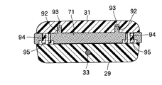
図20を併せて参照して、前記メカニカルキー12の突出側とは反対側でモジュールケース29およびモジュールカバー31間には、図示しないキーホルダを連結するための金属製のホルダリング71が、その大部分を把持ケース13から突出させるようにして挟持される。   Referring also to FIG. 20, a metal holder ring 71 for connecting a key holder (not shown) between the module case 29 and the module cover 31 on the side opposite to the projecting side of the mechanical key 12 is large. The portion is clamped so as to protrude from the gripping case 13.

しかもモジュールケース29およびモジュールカバー31の一方、この実施例ではモジュールカバー31には、複数たとえば一対の有底の嵌合孔92,92が設けられ、前記ホルダリング71には、前記両嵌合孔92…にそれぞれ嵌合する嵌合突起93,93が一体に突設される。   In addition, one of the module case 29 and the module cover 31, in this embodiment, the module cover 31 is provided with a plurality of, for example, a pair of bottomed fitting holes 92, 92, and the holder ring 71 has both the fitting holes. The fitting projections 93, 93 that are respectively fitted to 92 ... are projected integrally.

また前記ホルダリング71には、複数たとえば一対の係合孔94,94が設けられており、モジュールカバー31には、前記両係合孔94…にそれぞれ弾発係合する係合爪95,95が一体に突設される。   The holder ring 71 is provided with a plurality of, for example, a pair of engagement holes 94, 94. The module cover 31 has engagement claws 95, 95 that elastically engage with the engagement holes 94. Is integrally projected.

次にこの実施例の作用について説明すると、メカニカルキー12は、シリンダ錠24に差し込み可能なキープレート15の一端部にキーヘッド16が結合されて成るものであり、このメカニカルキー12のキーヘッド16は、メカニカルキー12の全体を格納する格納位置ならびにキープレート15を突出させる突出位置間で回動することを可能として把持ケース13に支持されるのであるが、シリンダ錠24側に特定のIDコード信号を発信するトランスポンダー14が、キーヘッド16に内蔵されている。   Next, the operation of this embodiment will be described. The mechanical key 12 is formed by connecting a key head 16 to one end of a key plate 15 that can be inserted into the cylinder lock 24. Is supported by the gripping case 13 so as to be able to rotate between a storage position for storing the entire mechanical key 12 and a projecting position for projecting the key plate 15, but a specific ID code is provided on the cylinder lock 24 side. A transponder 14 for transmitting a signal is built in the key head 16.

したがって破損等の原因によってメカニカルキー12が把持ケース13から脱落してしまった場合でも、メカニカルキー12のキーヘッド16にトランスポンダー14が内蔵されているので、メカニカルキー12だけでシリンダ錠24との間での信号の授受が可能であり、メカニカルキー12だけでエンジン始動を行うことができる。   Therefore, even when the mechanical key 12 is dropped from the gripping case 13 due to damage or the like, since the transponder 14 is built in the key head 16 of the mechanical key 12, the mechanical key 12 alone is connected to the cylinder lock 24. The engine can be started only with the mechanical key 12.

またロアケース27が備える支軸27bの周囲には、メカニカルキー12のキーヘッド16に一端を係合せしめた状態でばね力を発揮しない自然な状態にある前記ねじりばね50の他端をロアケース27と非締結状態にあるアッパケース28のばね係止部28cに係合させるようにしたばね係合位置と、ばね係止部28cにねじりばね50を係合したアッパケース28をねじりばね50に弾発力を発揮させる側に所定量回動させた締結位置とが設定されており、支軸27bの軸線まわりに前記ばね係合位置から前記締結位置に回動したアッパケース28に当接する位置決め規制部27dがロアケース27の連結壁部27cに設けられる。   Further, the other end of the torsion spring 50 in a natural state in which one end is engaged with the key head 16 of the mechanical key 12 and does not exert a spring force is provided around the support shaft 27b provided in the lower case 27 with the lower case 27. The spring engagement position in which the upper case 28 in the non-fastened state is engaged with the spring engagement portion 28c and the upper case 28 in which the torsion spring 50 is engaged with the spring engagement portion 28c are elastically applied to the torsion spring 50. A fastening position rotated by a predetermined amount on the side that exerts a force is set, and a positioning restriction portion that contacts the upper case 28 rotated from the spring engagement position to the fastening position around the axis of the support shaft 27b. 27 d is provided on the connecting wall portion 27 c of the lower case 27.

したがってキーヘッド16の支持孔48にロアケース27の支軸27bを嵌合し、一端をキーヘッド16に係合せしめて自然な状態にあるねじりばね50の他端を、前記支軸27bの先端部に支持筒部28aを嵌合、連結した状態でばね係合位置に配置したアッパケース28のばね係止部28cに係合し、アッパケース28をばね係合位置からねじりばね50が弾発力を発揮する側に捩じるようにして支軸27bのまわりに回動操作して位置決め規制部27dに当接させると、ロアケース27が締結位置に達するとともにねじりばね50が所定の弾発力を発揮するように捩じられることになり、この状態でアッパケース28をロアケース27に締結するので、特別な工具や熟練作業員であることを不要とした簡単な組付け作業でアッパケース28をロアケース27に締結することができ、作業工数の低減も可能となる。   Therefore, the support shaft 48 of the lower case 27 is fitted into the support hole 48 of the key head 16 and one end of the support shaft 48 is engaged with the key head 16 so that the other end of the torsion spring 50 is in a natural state at the tip of the support shaft 27 b. With the support cylinder portion 28a fitted and connected, it engages with the spring locking portion 28c of the upper case 28 arranged at the spring engagement position, and the torsion spring 50 exerts the elastic force from the spring engagement position. When the lower case 27 reaches the fastening position and the torsion spring 50 exerts a predetermined elastic force when it is rotated about the support shaft 27b so as to be twisted toward the exerting side and brought into contact with the positioning restricting portion 27d. Since the upper case 28 is fastened to the lower case 27 in this state, the upper case can be easily assembled without requiring a special tool or a skilled worker. 8 can be fastened to the lower case 27, also becomes possible reduction of man-hours.

しかもロアケース27およびアッパケース28には、コイルばね42のばね力を、ロアケース27から離反する側にばね付勢されるアッパケース28が前記締結位置にある状態で相互に圧接する方向で受けるようにして当接する当接面88,89が、支軸27bの軸線に直交する平面に沿うようにしてそれぞれ形成されるので、位置決め規制部27dに当接するまでアッパケース28を回動すると、アッパケース28に作用しているばね力でロアケース27およびアッパケース28の当接面88,89が相互に圧接することになり、当接面88,89相互の圧接による摩擦力でアッパケース28から手を離してもアッパケース28が締結位置からばね係合位置側に戻ってしまうことがなく、したがって組付け作業がより容易となる。   In addition, the lower case 27 and the upper case 28 receive the spring force of the coil spring 42 in a direction in which the upper case 28 urged toward the side away from the lower case 27 is in pressure contact with each other in the state of being in the fastening position. Since the contact surfaces 88 and 89 that contact each other are formed along a plane perpendicular to the axis of the support shaft 27b, the upper case 28 is rotated when the upper case 28 is rotated until it contacts the positioning restricting portion 27d. The abutting surfaces 88 and 89 of the lower case 27 and the upper case 28 are pressed against each other by the spring force acting on the upper case 28, and the hand is released from the upper case 28 by the frictional force generated by the pressing of the abutting surfaces 88 and 89. However, the upper case 28 does not return from the fastening position to the spring engagement position side, and therefore the assembling work becomes easier.

またモジュールケース29およびモジュールカバー31間に挟まれる金属製のホルダリング71に、モジュールカバー31に設けられた一対の嵌合孔92…にそれぞれ嵌合する嵌合突起93…が一体に突設され、ホルダリング72に設けられたたとえば一対の係合孔94…にそれぞれ弾発係合する係合爪95…がモジュールカバー31に一体に突設されるので、モジュールカバー31の係合爪95…をホルダリング71の係合孔94…に弾発係合するとともにホルダリング71の嵌合突起93…をモジュールカバー31の嵌合孔92…に嵌合した状態で、モジュールケース29およびモジュールカバー31を結合することによりホルダリング71がモジュールケース29およびモジュールカバー31間に挟持されるようにして把持ケース13に取付けられることになる。   The metal holder ring 71 sandwiched between the module case 29 and the module cover 31 is integrally provided with fitting protrusions 93 that respectively fit in a pair of fitting holes 92 provided in the module cover 31. Further, for example, engaging claws 95 that are elastically engaged with a pair of engaging holes 94 provided in the holder ring 72 are projected integrally with the module cover 31, so that the engaging claws 95 of the module cover 31. Are elastically engaged with the engagement holes 94 of the holder ring 71 and the fitting projections 93 of the holder ring 71 are fitted to the fitting holes 92 of the module cover 31. Are held so that the holder ring 71 is sandwiched between the module case 29 and the module cover 31. It will be attached.

しかも両係合爪95…の係合孔94…への弾発係合によってホルダリング71をモジュールカバー31に仮組付けすることが可能であるので組付けが容易となり、またホルダリング71が備える一対の嵌合突起93…をモジュールカバー31の嵌合孔92…に嵌合するようにしているので、ホルダリング71に外力が作用してもその外力が複数箇所に分散されてホルダリング71の把持ケース13への取付け箇所に作用することになり、組付け強度を高めることができる。   Moreover, since the holder ring 71 can be temporarily assembled to the module cover 31 by the elastic engagement of the engagement claws 95 to the engagement holes 94, the assembly is facilitated, and the holder ring 71 is provided. Since the pair of fitting protrusions 93 are fitted in the fitting holes 92 of the module cover 31, even if an external force is applied to the holder ring 71, the external force is dispersed at a plurality of locations and the holder ring 71 It will act on the attachment location to the gripping case 13, and the assembly strength can be increased.

さらにロアケース27は、モジュールケース29の内面側にインサート結合される基板27aと、該基板27aに直角に連なる支軸27bを有するものであり、このロアケース27をモジュールケース29にインサート結合する際に、支軸27bの軸線に直交する方向でのロアケース27の位置を定めつつモジュールケース29の内面側を成形する金型82に、支軸27bに係合して当該支軸27bの軸方向に沿うロアケース27の位置を定めるスライド金型84が、支軸27bの半径方向に移動することを可能として配設されている。   Furthermore, the lower case 27 has a substrate 27a that is insert-coupled to the inner surface side of the module case 29, and a support shaft 27b that is connected to the substrate 27a at a right angle. When the lower case 27 is insert-coupled to the module case 29, A lower case along the axial direction of the support shaft 27b by engaging the support shaft 27b with a mold 82 for molding the inner surface side of the module case 29 while determining the position of the lower case 27 in a direction orthogonal to the axis of the support shaft 27b. A slide mold 84 that determines the position of the shaft 27 is disposed so as to be movable in the radial direction of the support shaft 27b.

したがってロアケース27の基板27aをモジュールケース29の内面側にインサート結合する際に、支軸27bの軸線に沿う方向すなわちモジュールケース29の厚み方向でのロアケース27の位置はスライド金型84によって一定に定められることになり、モジュールケース29の成形時の樹脂圧力によってもロアケース27が移動することはなく、モジュールケース29の厚み方向でのロアケース27の位置を確実に一定に定めることができるようにし、モジュールケース29の外面を安定した確実な意匠面とすることができる。   Therefore, when the board 27a of the lower case 27 is insert-coupled to the inner surface side of the module case 29, the position of the lower case 27 in the direction along the axis of the support shaft 27b, that is, in the thickness direction of the module case 29 is fixed by the slide mold 84. Therefore, the lower case 27 does not move due to the resin pressure at the time of molding the module case 29, and the position of the lower case 27 in the thickness direction of the module case 29 can be determined with certainty. The outer surface of the case 29 can be a stable and reliable design surface.

以上、本発明の実施例を説明したが、本発明は上記実施例に限定されるものではなく、特許請求の範囲に記載された本発明を逸脱することなく種々の設計変更を行うことが可能である。   Although the embodiments of the present invention have been described above, the present invention is not limited to the above-described embodiments, and various design changes can be made without departing from the present invention described in the claims. It is.

メカニカルキーが突出位置にある状態でのキーユニットの側面図である。It is a side view of a key unit in the state where a mechanical key exists in a protrusion position. メカニカルキーが格納位置にある状態でのキーユニットの側面図である。It is a side view of a key unit in the state where a mechanical key exists in a storing position. 図2の3矢視図である。FIG. 3 is a view taken in the direction of arrow 3 in FIG. 2. メカニカルキーを図1とは反対側から見た側面図である。It is the side view which looked at the mechanical key from the opposite side to FIG. 図4の5−5線断面図である。FIG. 5 is a sectional view taken along line 5-5 of FIG. メカニカルキーをシリンダ錠に差し込んだ状態を示す縦断側面図である。It is a vertical side view which shows the state which inserted the mechanical key in the cylinder lock. キーユニットの分解斜視図である。It is a disassembled perspective view of a key unit. 図1の8−8線断面図である。FIG. 8 is a cross-sectional view taken along line 8-8 in FIG. 1. 図8の9矢示部拡大図である。FIG. 9 is an enlarged view of a portion indicated by an arrow 9 in FIG. 8. ロアケースがインサート結合された状態のモジュールケースの一部を示す側面図である。It is a side view which shows a part of module case of the state where the lower case was insert-joined. モジュールケースの金型成形時の状態を図10の11−11線に沿って示す断面図である。It is sectional drawing which shows the state at the time of metal mold | die molding of a module case along the 11-11 line of FIG. モジュールケースの金型成形時の状態を図10の12−12線に沿って示す断面図である。It is sectional drawing which shows the state at the time of metal mold | die molding of a module case along the 12-12 line of FIG. アッパケースの斜視図である。It is a perspective view of an upper case. 支軸にメカニカルキーを回動可能に支持した状態を示す側面図である。It is a side view which shows the state which supported the mechanical key on the spindle so that rotation was possible. 図9の15−15線断面図である。FIG. 15 is a cross-sectional view taken along line 15-15 in FIG. 9. 図15の16−16線断面図である。FIG. 16 is a cross-sectional view taken along line 16-16 in FIG. 15. アッパケースがばね係合位置にある状態を示す側面図である。It is a side view which shows the state which has an upper case in a spring engagement position. 締結位置に回動したアッパケースをロアケースに締結した状態での図17に対応した一部切欠き側面図である。FIG. 18 is a partially cutaway side view corresponding to FIG. 17 in a state where the upper case rotated to the fastening position is fastened to the lower case. 図18の19−19線断面図である。FIG. 19 is a cross-sectional view taken along line 19-19 in FIG. 18. 図1の20−20線断面図である。FIG. 20 is a sectional view taken along line 20-20 in FIG. 1.

符号の説明Explanation of symbols

11・・・キーユニット
12・・・メカニカルキー
13・・・把持ケース
15・・・キープレート
16・・・キーヘッド
24・・・シリンダ錠
27・・・支持部材としてのロアケース
27b・・・支軸
27d・・・位置決め規制部
28・・・挟持部材としてのアッパケース
28a・・・支持筒部
28c・・・ばね係止部
48・・・支持孔
50・・・ねじりばね
88,89・・・当接面
DESCRIPTION OF SYMBOLS 11 ... Key unit 12 ... Mechanical key 13 ... Holding case 15 ... Key plate 16 ... Key head 24 ... Cylinder lock 27 ... Lower case 27b as support member ... Support Shaft 27d ... Positioning restricting part 28 ... Upper case 28a as a clamping member ... Supporting cylinder part 28c ... Spring locking part 48 ... Support hole 50 ... Torsion spring 88, 89 ...・ Contact surface

Claims (2)

シリンダ錠(24)に差し込み可能なキープレート(15)の一端部に円形の支持孔(48)が設けられるキーヘッド(16)が結合されて成るメカニカルキー(12)と、前記支持孔(48)に嵌合される支軸(27b)を有する支持部材(27)ならびに前記キーヘッド(16)を前記支持部材(27)との間に挟んで前記支持部材(27)に締結される挟持部材(28)とを構成要素の一部として有するとともに前記メカニカルキー(12)の全体を格納する格納位置ならびに前記キープレート(15)を突出させる突出位置間で前記メカニカルキー(12)を回動させることを可能として前記キーヘッド(16)を支持する把持ケース(13)と、前記キープレート(15)を突出させる側に前記メカニカルキー(12)を付勢する弾発力を発揮するようにして一端が前記キーヘッド(16)に係合されるとともに他端が前記挟持部材(28)に設けられたばね係止部(28c)に係合されるねじりばね(50)とを備えるキーユニットにおいて、前記挟持部材(28)に前記支軸(27b)の先端部に嵌合、連結される支持筒部(28a)が一体に設けられ、前記支軸(27b)の周囲には、前記キーヘッド(16)に一端を係合せしめた状態でばね力を発揮しない自然な状態にある前記ねじりばね(50)の他端を前記支持部材(27)と非締結状態にある前記挟持部材(28)の前記ばね係止部(28c)に係合させるようにしたばね係合位置と、前記ばね係止部(28c)に前記ねじりばね(50)を係合した前記挟持部材(28)を前記ねじりばね(50)に弾発力を発揮させる側に所定量回動させた締結位置とが設定され、前記支軸(27b)の軸線まわりに前記ばね係合位置から前記締結位置に回動した前記挟持部材(28)に当接する位置決め規制部(27d)が前記支持部材(27)に設けられ、位置決め規制部(27d)に当接した状態の前記挟持部材(28)が前記支持部材(27)に締結されることを特徴とするキーユニット。   A mechanical key (12) in which a key head (16) provided with a circular support hole (48) is coupled to one end of a key plate (15) that can be inserted into the cylinder lock (24), and the support hole (48). And a support member (27) having a support shaft (27b) fitted to the support member (27) and a clamping member fastened to the support member (27) with the key head (16) interposed between the support member (27) and the support member (27). (28) as a part of the constituent elements, and the mechanical key (12) is rotated between a storage position for storing the entire mechanical key (12) and a protruding position for protruding the key plate (15). A gripping case (13) that supports the key head (16) and the mechanical key (12) are biased toward the side from which the key plate (15) protrudes. A torsion spring (50) having one end engaged with the key head (16) and the other end engaged with a spring locking portion (28c) provided on the clamping member (28) so as to exert a generating force. ) Is provided integrally with a support cylinder portion (28a) fitted and connected to the tip end portion of the support shaft (27b) on the clamping member (28). Around the other end, the other end of the torsion spring (50) in a natural state in which one end is engaged with the key head (16) and does not exert a spring force is not fastened to the support member (27). A spring engagement position in which the pinching member (28) is engaged with the spring locking portion (28c), and the pinching in which the torsion spring (50) is engaged with the spring locking portion (28c). The member (28) is bounced to the torsion spring (50). The fastening position rotated by a predetermined amount is set on the side where the force is exerted, and is applied to the clamping member (28) rotated from the spring engagement position to the fastening position around the axis of the support shaft (27b). A positioning restricting portion (27d) in contact with the supporting member (27) is provided, and the clamping member (28) in contact with the positioning restricting portion (27d) is fastened to the support member (27). A key unit. 前記支持部材(27)および前記挟持部材(28)には、前記支持部材(27)から離反する側に前記挟持部材(28)を付勢するばね力を前記挟持部材(28)が前記締結位置にある状態では相互に圧接する方向で受けるようにして当接する当接面(88,89)が、前記支軸(27b)の軸線に直交する平面に沿うようにしてそれぞれ形成されることを特徴とする請求項1記載のキーユニット。   In the support member (27) and the clamping member (28), the clamping member (28) has a spring force that biases the clamping member (28) toward the side away from the support member (27). In this state, the contact surfaces (88, 89) that contact each other so as to be received in the direction in which they are pressed against each other are formed along a plane perpendicular to the axis of the support shaft (27b). The key unit according to claim 1.
JP2006079331A 2006-03-22 2006-03-22 Key unit Expired - Fee Related JP4673776B2 (en)

Priority Applications (2)

Application Number Priority Date Filing Date Title
JP2006079331A JP4673776B2 (en) 2006-03-22 2006-03-22 Key unit
US11/712,586 US7370501B2 (en) 2006-03-22 2007-03-01 Key unit

Applications Claiming Priority (1)

Application Number Priority Date Filing Date Title
JP2006079331A JP4673776B2 (en) 2006-03-22 2006-03-22 Key unit

Publications (2)

Publication Number Publication Date
JP2007255014A JP2007255014A (en) 2007-10-04
JP4673776B2 true JP4673776B2 (en) 2011-04-20

Family

ID=38629526

Family Applications (1)

Application Number Title Priority Date Filing Date
JP2006079331A Expired - Fee Related JP4673776B2 (en) 2006-03-22 2006-03-22 Key unit

Country Status (1)

Country Link
JP (1) JP4673776B2 (en)

Cited By (2)

* Cited by examiner, † Cited by third party
Publication number Priority date Publication date Assignee Title
JP2014190017A (en) * 2013-03-27 2014-10-06 Miwa Lock Co Ltd Portable type key
WO2016157793A1 (en) * 2015-03-31 2016-10-06 株式会社デンソー Anchoring structure for annular member and electronic key

Families Citing this family (3)

* Cited by examiner, † Cited by third party
Publication number Priority date Publication date Assignee Title
FR2952956B1 (en) * 2009-11-20 2011-12-09 Valeo Securite Habitacle RETRACTABLE INSERT KEY WITH IMPROVED MECHANICAL RESISTANCE
JP5518581B2 (en) * 2010-06-03 2014-06-11 株式会社東海理化電機製作所 Key unit and key unit assembly method
JP7269825B2 (en) * 2019-08-07 2023-05-09 アルプスアルパイン株式会社 portable key device

Family Cites Families (1)

* Cited by examiner, † Cited by third party
Publication number Priority date Publication date Assignee Title
DE3769923D1 (en) * 1986-10-20 1991-06-13 Siemens Ag DEVICE FOR REMOTELY CONTROLLING A LOCKING SYSTEM EQUIPPED WITH A RECEIVER, ESPECIALLY FOR MOTOR VEHICLES.

Cited By (4)

* Cited by examiner, † Cited by third party
Publication number Priority date Publication date Assignee Title
JP2014190017A (en) * 2013-03-27 2014-10-06 Miwa Lock Co Ltd Portable type key
WO2016157793A1 (en) * 2015-03-31 2016-10-06 株式会社デンソー Anchoring structure for annular member and electronic key
JP2016194198A (en) * 2015-03-31 2016-11-17 株式会社デンソー Fixing structure for annular member, and electronic key
US10271443B2 (en) 2015-03-31 2019-04-23 Denso Corporation Anchoring structure for annular member and electronic key

Also Published As

Publication number Publication date
JP2007255014A (en) 2007-10-04

Similar Documents

Publication Publication Date Title
US7370501B2 (en) Key unit
JP4673776B2 (en) Key unit
US20070062229A1 (en) Key for immobilizer
JP6180992B2 (en) Lid device
US6170729B1 (en) Nailing depth adjusting device for a power nailer
JP5171237B2 (en) Lid lock device
JP4648227B2 (en) Insert molding structure of support member in key unit
US8973956B2 (en) Latch device
EP1207255B1 (en) Mechanical module for a key, key provided with such a module and method of mounting such a module on a key
JPS6378977A (en) Body of door lock for car
JP2006249875A (en) Folding type storage case
US4800785A (en) Dual-drive ratchet wrench
JP6169999B2 (en) Portable device and assembly method thereof
JP4724025B2 (en) Key unit
JP5474012B2 (en) Lock device for vehicle door
JP4324571B2 (en) Actuator device
FR2815521A1 (en) Remote locking sender for motor vehicles with vehicle key retracting into remote unit shell, uses axially mobile pivot for key and spring to hold it in the extended position when not folded into the shell
JP4145903B2 (en) Sealing device
JP6400135B2 (en) Carabiner
WO2013061877A1 (en) Seatbelt retractor
WO2016068000A1 (en) Key unit
JP5112254B2 (en) Cylinder lock protector
JPS6020210Y2 (en) magnetic tape cartridge
JP2006249861A (en) Combination lock
CN111236764A (en) Mechanical lock and shared vehicle

Legal Events

Date Code Title Description
A621 Written request for application examination

Free format text: JAPANESE INTERMEDIATE CODE: A621

Effective date: 20080818

A977 Report on retrieval

Free format text: JAPANESE INTERMEDIATE CODE: A971007

Effective date: 20101126

TRDD Decision of grant or rejection written
A01 Written decision to grant a patent or to grant a registration (utility model)

Free format text: JAPANESE INTERMEDIATE CODE: A01

Effective date: 20110112

A01 Written decision to grant a patent or to grant a registration (utility model)

Free format text: JAPANESE INTERMEDIATE CODE: A01

A61 First payment of annual fees (during grant procedure)

Free format text: JAPANESE INTERMEDIATE CODE: A61

Effective date: 20110121

R150 Certificate of patent or registration of utility model

Free format text: JAPANESE INTERMEDIATE CODE: R150

Ref document number: 4673776

Country of ref document: JP

Free format text: JAPANESE INTERMEDIATE CODE: R150

FPAY Renewal fee payment (event date is renewal date of database)

Free format text: PAYMENT UNTIL: 20140128

Year of fee payment: 3

R250 Receipt of annual fees

Free format text: JAPANESE INTERMEDIATE CODE: R250

R250 Receipt of annual fees

Free format text: JAPANESE INTERMEDIATE CODE: R250

R250 Receipt of annual fees

Free format text: JAPANESE INTERMEDIATE CODE: R250

R250 Receipt of annual fees

Free format text: JAPANESE INTERMEDIATE CODE: R250

R250 Receipt of annual fees

Free format text: JAPANESE INTERMEDIATE CODE: R250

R250 Receipt of annual fees

Free format text: JAPANESE INTERMEDIATE CODE: R250

R250 Receipt of annual fees

Free format text: JAPANESE INTERMEDIATE CODE: R250

R250 Receipt of annual fees

Free format text: JAPANESE INTERMEDIATE CODE: R250

R250 Receipt of annual fees

Free format text: JAPANESE INTERMEDIATE CODE: R250

LAPS Cancellation because of no payment of annual fees