JP4673508B2 - Magnetic head and magnetic disk device - Google Patents
Magnetic head and magnetic disk device Download PDFInfo
- Publication number
- JP4673508B2 JP4673508B2 JP2001198587A JP2001198587A JP4673508B2 JP 4673508 B2 JP4673508 B2 JP 4673508B2 JP 2001198587 A JP2001198587 A JP 2001198587A JP 2001198587 A JP2001198587 A JP 2001198587A JP 4673508 B2 JP4673508 B2 JP 4673508B2
- Authority
- JP
- Japan
- Prior art keywords
- magnetic
- magnetic pole
- head
- recording
- pole
- Prior art date
- Legal status (The legal status is an assumption and is not a legal conclusion. Google has not performed a legal analysis and makes no representation as to the accuracy of the status listed.)
- Expired - Fee Related
Links
Images


Classifications
-
- G—PHYSICS
- G11—INFORMATION STORAGE
- G11B—INFORMATION STORAGE BASED ON RELATIVE MOVEMENT BETWEEN RECORD CARRIER AND TRANSDUCER
- G11B5/00—Recording by magnetisation or demagnetisation of a record carrier; Reproducing by magnetic means; Record carriers therefor
- G11B5/127—Structure or manufacture of heads, e.g. inductive
- G11B5/31—Structure or manufacture of heads, e.g. inductive using thin films
- G11B5/3109—Details
- G11B5/3116—Shaping of layers, poles or gaps for improving the form of the electrical signal transduced, e.g. for shielding, contour effect, equalizing, side flux fringing, cross talk reduction between heads or between heads and information tracks
-
- G—PHYSICS
- G11—INFORMATION STORAGE
- G11B—INFORMATION STORAGE BASED ON RELATIVE MOVEMENT BETWEEN RECORD CARRIER AND TRANSDUCER
- G11B5/00—Recording by magnetisation or demagnetisation of a record carrier; Reproducing by magnetic means; Record carriers therefor
- G11B5/127—Structure or manufacture of heads, e.g. inductive
- G11B5/1278—Structure or manufacture of heads, e.g. inductive specially adapted for magnetisations perpendicular to the surface of the record carrier
-
- G—PHYSICS
- G11—INFORMATION STORAGE
- G11B—INFORMATION STORAGE BASED ON RELATIVE MOVEMENT BETWEEN RECORD CARRIER AND TRANSDUCER
- G11B5/00—Recording by magnetisation or demagnetisation of a record carrier; Reproducing by magnetic means; Record carriers therefor
- G11B5/127—Structure or manufacture of heads, e.g. inductive
- G11B5/31—Structure or manufacture of heads, e.g. inductive using thin films
- G11B5/3109—Details
- G11B5/313—Disposition of layers
- G11B5/3143—Disposition of layers including additional layers for improving the electromagnetic transducing properties of the basic structure, e.g. for flux coupling, guiding or shielding
- G11B5/3146—Disposition of layers including additional layers for improving the electromagnetic transducing properties of the basic structure, e.g. for flux coupling, guiding or shielding magnetic layers
- G11B5/315—Shield layers on both sides of the main pole, e.g. in perpendicular magnetic heads
-
- G—PHYSICS
- G11—INFORMATION STORAGE
- G11B—INFORMATION STORAGE BASED ON RELATIVE MOVEMENT BETWEEN RECORD CARRIER AND TRANSDUCER
- G11B5/00—Recording by magnetisation or demagnetisation of a record carrier; Reproducing by magnetic means; Record carriers therefor
- G11B5/127—Structure or manufacture of heads, e.g. inductive
- G11B5/265—Structure or manufacture of a head with more than one gap for erasing, recording or reproducing on the same track
- G11B5/2652—Structure or manufacture of a head with more than one gap for erasing, recording or reproducing on the same track with more than one gap simultaneously operative
Description
【0001】
【発明の属する技術分野】
本発明は、磁気ディスク装置等の記録・再生に用いられる薄膜磁気ヘッド、特に垂直磁気記録ヘッド、及びこれらを使用した磁気ディスク装置に関する。
【0002】
【従来の技術】
現在、コンピュータ等の情報機器において情報の外部記憶装置として用いられている磁気ディスク装置には、記録を誘導型薄膜ヘッドで行い再生を磁気抵抗効果型ヘッドで行う記録再生分離型ヘッドが主に用いられている。記録ヘッドからの漏洩磁束で媒体に記録パターンを形成する記録方式としては、面内(長手)記録方式と垂直記録方式の2種類が代表的である。今後、記録密度の高密度化を達成するために、従来の面内(長手)記録方式に代わる磁気記録方式として、垂直磁気記録方式が有望視されている。
【0003】
面内(長手)記録方式では、記録ヘッドのギャップからの漏洩磁束によって媒体上の磁性層が媒体進行方向(トレーリング方向)と同方向あるいは逆方向に磁化されることにより、媒体上に記録パターンが形成される。一方、磁気ディスク装置等に考案されている最近の垂直磁気記録方式においては、特開平4−57205号公報に開示されているように、記録ヘッドは主磁極と補助磁極から構成されており、記録媒体は主として2層記録媒体でその構成は記録ヘッドに近い側に形成された記録層(垂直磁化層)とその下地の軟磁性層からなり、記録ヘッドの主磁極と軟磁性下地層と補助磁極とが磁気的に結合され閉磁路を形成することが可能となっている。この方式によれば、記録ヘッドの主磁極と媒体の軟磁性下地層との距離が、主磁極と補助磁極との間隔よりも十分狭ければ、主磁極から漏洩した磁束は記録層を膜厚方向即ち媒体面に対し垂直に磁化して軟磁性下地層を経由して補助磁極に帰ってくる。このため、媒体上の記録パターンは媒体の膜厚方向に形成されることとなり、これが垂直磁気記録の名称のもととなっている。
なお、垂直磁気記録方式においても面内(長手)磁気記録方式と同様に、再生ヘッドとして、磁気抵抗効果素子、特に巨大磁気抵抗効果を利用したGMRヘッドまたはトンネル磁気抵抗効果を利用したTMRヘッド等が用いられている。
【0004】
従来用いられている記録再生分離型の垂直磁気記録ヘッドの構造の概略を図1に示した。図1において、垂直磁気記録用の記録ヘッドは、磁気抵抗効果素子を用いた再生ヘッドの上に積層された構造となっている。図1で垂直磁気記録用薄膜ヘッドは、主磁極1、補助磁極2、導体コイル3、導体コイル3と主磁極1並びに補助磁極2を絶縁する絶縁膜4から成る。垂直磁気記録用ヘッドでは、主磁極の記録トラック幅を狭くし且つ主磁極から漏洩する磁束密度を高くする目的で、メッキ法などによって主磁極を形成した後に、主磁極をFIBなどでトリミングする場合もある。このため、基板上に再生ヘッドを形成した後、補助磁極、主磁極の順に形成される場合が多い。垂直磁気記録用の記録ヘッドと面内磁気記録用の記録ヘッドとの大きな相違点は、面内記録用のヘッドでは記録媒体対向面からみたとき、主磁極と補助磁極との間隔が非常に狭い(例えば0.2μm)のに対し、垂直記録用ヘッドではこれが5〜10μmと離れていることである。
【0005】
図1において、再生ヘッドは外部磁界に依存して電気抵抗が変化する磁気抵抗効果膜5、磁区制御膜6及び電極7からなる磁気抵抗効果素子と、不要な磁界を遮断する上下のシールド層2,8、並びに図中には示されていないが磁気抵抗効果素子とシールド間を絶縁する絶縁膜を備える。図1の記録再生分離型ヘッドでは、記録ヘッドの補助磁極2が再生ヘッドの上部シールドを兼ねている。記録ヘッドの補助磁極と再生ヘッドの上部シールドが別個に設けられている場合、これらの磁性体材料からなる層の間には磁気的分離膜が存在する。
【0006】
磁気ディスク装置では、記録媒体を回転させ、上記のような記録再生分離型ヘッドが搭載されたスライダが媒体面に対し一定の間隔で浮上しながら信号の記録再生を行っている。このとき、信号が記録・再生されるトラックは同心円構造をしている。媒体上のトラックに信号(磁化パターン)を正確に記録・再生するために位置決め制御が必要であり、現在ではセクタサーボ方式を用いた位置決め制御が主流となっている。セクタサーボ方式では、円周状のトラックを複数のセクタに分割し、それぞれのセクタの先頭にサーボ領域を設け、その後に信号が記録されるデータ領域が設けられている。磁気ヘッドは、記録・再生を行う際、セクタ領域に設けられたサーボパターンを利用してトラック上に位置決めを行っている。また、現在の磁気ディスク装置では、スライダを先端に搭載したサスペンションの根本が固定されており、サスペンションはその固定点を軸に動く構造になっている。このため、媒体の内周および外周近傍部にあるトラック上の信号を記録・再生する際に、スライダはトラックに対しヨー角を持つ。
【0007】
【発明が解決しようとする課題】
従来の垂直磁気記録用薄膜単磁極ヘッドは、面内記録用ヘッドと比較して、媒体対向面からみたときに主磁極と補助磁極との間隔が5〜10μm離れて形成され、また基板上に再生ヘッド、補助磁極、主磁極の順に形成されるため、主磁極と再生ヘッドとの間隔は10μm以上となる。セクタサーボ方式では、サーボ領域に記録されているサーボパターンを再生ヘッドで検出してトラック上に位置決めを行ってから、トラック上のデータ領域に信号を記録する。上記のように主磁極と再生ヘッドとの間隔が広くなると、サーボ領域のサーボパターンを検出した後に、データ領域に記録ヘッドが到達するまでに時間がかかる。言いかえると、サーボ領域とデータ領域の間に存在する、信号記録に使用できない領域の長さが増加することになる。このため、従来の垂直磁気記録用薄膜単磁極ヘッドを用いた垂直記録方式では、面内(長手)記録方式と比較して、1トラックあたりデータ領域が占める割合、即ちフォーマット効率が低下する。
【0008】
トラック上に信号を記録する際、トラック上にある再生ヘッドでサーボパターンを検出した後に記録ヘッドがトラック上に来るように、スライダを移動させなければならない。媒体の内周および外周近傍部のトラックにおいては、ヨー角がついているために、スライダの移動量が大きくなり、位置決め制御(サーボ)が難しい。主磁極と再生ヘッドとの間隔が広くなると、このスライダの移動量がさらに増大することになり、サーボ系の設計が難しくなる。このため、従来の垂直磁気記録用薄膜単磁極ヘッドを用いた垂直記録方式では、面内(長手)記録方式と比較してサーボが難しくなる。
【0009】
また、従来の垂直磁気記録用薄膜単磁極ヘッドを用いた垂直記録方式では、補助磁極が主磁極と同じ記録トラック上になるように形成されるため、記録後消去に代表されるように主磁極から出て媒体の軟磁性下地層を経由して補助磁極にリターンしてくる磁束によって媒体上の記録パターンが影響を受けやすい。更に、補助磁極を形成した後に主磁極を積層するため、プロセス工程数が多くなり、記録ヘッドの作成に時間がかかる。
【0010】
なお、IEEE Trans. Magn., vol.MAG-23, no.5, pp.2070-2072 (1987)には、主磁極の周りに複数の補助磁極を配置したバルクヘッドが記載されている。しかし、このヘッドは記録、再生両用ヘッドであり、MR素子等の再生専用の素子を持たないため、本発明が解決しようとしている再生素子と主磁極との間の間隔が離れていることに起因する問題の所在、あるいは再生素子と主磁極との間隔を狭める具体的方法については何も示唆しない。
【0011】
本発明は、このような従来技術の問題点に鑑み、従来の垂直磁気記録用薄膜単磁極ヘッドよりもフォーマット効率が高く、サーボが容易な垂直磁気記録用薄膜単磁極ヘッド及びその磁気ヘッドを使用した磁気ディスク装置を提供することを目的とする。本発明は、また、記録後消去に代表されるようなリターン磁束による媒体上の記録パターンの撹乱が生じにくい垂直磁気記録用薄膜単磁極ヘッド及びその磁気ヘッドを使用した磁気ディスク装置を提供することを目的とする。本発明は、更に、プロセス時間短縮可能な構造を持つ垂直磁気記録用薄膜単磁極ヘッド及びその磁気ヘッドを使用した磁気ディスク装置を提供することを目的とする。
【0012】
【課題を解決するための手段】
本発明では、再生用ヘッドと記録用ヘッドからなる記録再生分離型の垂直磁気記録用薄膜単磁極ヘッドにおいて、記録媒体対向面からみたときに再生用ヘッドの再生素子と記録用ヘッドの主磁極との間に補助磁極を配置しない構造とすることにより上記目的を達成する。
【0013】
媒体対向面からみたとき、本発明の目的にかなう主磁極と補助磁極の配置例として、図2〜6に示すような各種の配置を考えることができる。図2〜6において、垂直磁気記録用薄膜単磁極ヘッドは、基板13上に形成された一対のシールド層10,12とその間に形成された再生素子11からなる再生用ヘッドの上に形成される。
【0014】
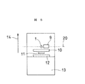
まず、図2に示すように、主磁極1と磁気的に接続された1つの補助磁極9が、主磁極1に対しトレーリング方向14と直交する方向に配置された場合が考えられる。第二に、図3に示すように、主磁極1と磁気的に接続された補助磁極の数が2であり、2つの補助磁極9,17が主磁極1を挟んでトレーリング方向14と直交する方向に配置された場合が考えられる。また、図4に示すように、主磁極1と磁気的に接続された補助磁極の数が3であり、第一の補助磁極9と第二の補助磁極17の再生ヘッドに近い側の面が、トレーリング方向14に略直交する同一直線15の上にあるように配置され、第三の補助磁極18の中心と主磁極1の中心を結ぶ直線19がトレーリング方向14に対し略平行方向になるように配置され、かつ第三の補助磁極18の面積が第一並びに第二の補助磁極9,17の面積よりも広くなっている場合が考えられる。
【0015】
図2〜4において、媒体対向面からみた場合の主磁極及び補助磁極の配置として、主磁極の再生ヘッドに近い側の面と補助磁極の再生ヘッドに近い側の面が同一直線15の上にあるようにしたが、配置方法としてはこれら以外にも可能である。例えば、図5に示すように媒体対向面からみたときに、主磁極の中心と補助磁極の中心を結ぶ直線20がトレーリング方向14と略直交するように配置することも可能である。また、2つ以上の補助磁極が存在するとき、図6に示すように、それぞれの補助磁極における再生ヘッドに近い側の面同士がトレーリング方向14に対し直交方向の同一直線15の上にあり、かつ主磁極1における再生ヘッドに近い側の面が上記直線15と同一直線上にない配置も可能である。図6の配置の場合、再生素子11から主磁極1の上面までの距離が再生素子11から補助磁極9,17までの距離より小さくなっている。尚、主磁極と補助磁極の配置、並びに補助磁極の数に関しては、上述以外の場合も可能である。
【0016】
主磁極と補助磁極が図2〜6に示される配置のとき、再生ヘッドを構成する再生素子11の中心と主磁極1の中心を結ぶ直線をトレーリング方向14へ射影したときの長さを5μm以下、できれば3μm以下とすることが望ましい。このように主磁極と再生ヘッドの間隔をなるべく近接させることにより、記録トラックのフォーマット効率を向上させ、またサーボを容易にすることが可能となる。
【0017】
図2〜6に示した主磁極と補助磁極の配置は、記録媒体対向面からみたときに、再生素子と記録用ヘッドの主磁極との間に補助磁極が存在しない配置を代表するものである。このように主磁極と補助磁極が配置されるとき、主磁極によって記録パターンが形成される記録トラックとは別のトラックの上に補助磁極が存在するように補助磁極を配置することが可能である。すなわち、主磁極と補助磁極との間隔dは、媒体上の記録トラック幅よりも広くなるように形成することが可能である。主磁極と補助磁極との間隔dは、記録トラック幅よりも広くなるように0.5μmから1μmの範囲に設定することが望ましい。ただし、この間隔よりも短く、もしくは長く設定することも可能である。このように主磁極と補助磁極との間隔dを記録トラック幅よりも広くした場合、図7示したように、主磁極1から漏洩した磁束21は媒体22の記録層23を膜厚方向すなわち媒体面に対し垂直に磁化して、軟磁性下地層24を経由し、主磁極直下の記録トラック25とは異なる別の記録トラック26上に形成された補助磁極9に返ってくるため、記録後消去などに代表されるようなリターン磁束による記録パターンの撹乱が生じる可能性が低くなる。更に補助磁極の数を2以上に増加させれば、補助磁極が1つの場合に比べて補助磁極に返ってくる磁束密度を低下させることができるので、記録後消去などに代表される記録パターンの撹乱現象の更なる防止が可能となる。
【0018】
図2〜4に示したように、媒体対向面からみたとき、主磁極1の再生ヘッドに近い側の面と補助磁極9(17)の再生ヘッドに近い側の面が同一直線15上にあるように各磁極を配置するとき、主磁極と補助磁極は同一の平坦化膜兼磁気的分離膜の上に形成することが可能である。平坦化膜兼磁気的分離膜としては、アルミナまたは二酸化シリコンまたはこれらの混合膜を使用することができる。平坦化膜兼磁気的分離膜のトレーリング方向の膜厚は、0.5μmから1μm程度あれば良い。このように、同一の平坦化膜兼磁気的分離膜上に主磁極と補助磁極を形成することで、記録ヘッドの作製プロセスの工程数を低減することができ、結果としてプロセス時間を短縮することが可能となる。
【0019】
主磁極と補助磁極の配置が図4のとき、記録媒体対向面からみたときに、第三の補助磁極18を第一、第二の補助磁極9,17並びに主磁極1の上に形成し、第三の補助磁極18は記録ヘッドに対するアンテナ効果防止用のシールドとしての機能も合わせ持つことができる。アンテナ効果とは垂直記録に特有の問題であり、記録ヘッドが記録動作をしていないときハードディスク筐体内外の磁場発生源から出た磁束が主磁極、補助磁極に入り、結果として媒体上の記録パターンを撹乱する現象である。アンテナ効果は一種の記録後消去と考えることもできる。図4に示したように、主磁極のまわりにシールドを兼ねるような面積の広い補助磁極を配置することにより、上記のアンテナ効果を回避することが可能となる。
【0020】
図2のように主磁極と補助磁極を配置した場合、主磁極の励磁用コイルは図8に示したように形成することが可能である。つまり、主磁極1に接続した磁性膜の柱27を記録媒体対向面に平行になるように形成し、これを取り囲むように励磁用コイル3を形成する。この形状は、主磁極1の媒体対向面における先端に近い位置に励磁用コイル3を配置することが可能であるため、記録磁界強度を強くすることが可能になる。なお、図2以外の主磁極と補助磁極の配置であっても、主磁極と磁気的に接続されかつ記録媒体対向面に平行に形成された磁性膜の柱を囲むように、励磁用コイルを形成することが可能である。また、図8に示した以外のコイルの配置も可能である。
【0021】
図2に示したように垂直記録ヘッドを構成した場合、再生用ヘッドとして、外部磁界の変化に対応して電気抵抗が変化する磁気抵抗効果素子を用いることが可能である。この場合、巨大磁気抵抗効果を利用した巨大磁気抵抗効果素子またはトンネル磁気抵抗効果を用いたトンネル磁気抵抗効果素子を使用することが好ましい。ただし、上記以外の磁気抵抗効果素子の使用も可能である。
【0022】
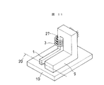
図11は、図5のように主磁極と補助磁極を配置した場合の、主磁極の励磁用コイルの形成例を示す図である。このコイル配置は基本的に図8のコイル配置と同じである。ただし、主磁極1と上部シールド10との間の磁気的分離膜は、補助磁極9と上部シールド10との間の磁気的分離膜より厚い。
【0023】
図12は、図6のように主磁極と補助磁極を配置した場合の、主磁極の励磁用コイルの形成例を示す図である。主磁極1は補助磁極9,17より上部シールド10に近い位置に形成されている。各磁極1,9,17に記録媒体対向面に平行な磁性膜の柱を接続し、3本の柱を上部で接続することで主磁極と第一及び第二の補助磁極を磁気的に結合し、主磁極1に接続した磁性膜の柱27取り囲むように励磁用コイル3を形成した。
【0024】
以上をまとめると、本発明による磁気ヘッドは、一対の磁気シールド層とその間に形成された再生素子とを備える再生用ヘッドと、記録媒体対向面で磁気ギャップを介して対向し内部で接続した軟磁性薄膜からなる主磁極及び補助磁極と当該主磁極及び補助磁極によって形成される磁気回路に磁気的に結合したコイルとを備える垂直磁気記録用ヘッドとを含む磁気ヘッドにおいて、補助磁極は、記録媒体対向面からみたとき、再生素子と主磁極との間を除く領域に配置されていることを特徴とする。
記録媒体対向面からみたとき、再生素子の中心と主磁極の中心とを結ぶ直線をトレーリング方向へ射影したときの長さは5μm以下であることが好ましい。この長さが5μmを越えるようになるとサーボが困難になる。
【0025】
本発明の一態様による磁気ヘッドは、1又は複数の補助磁極を備え、記録媒体対向面からみたとき、少なくとも1つの補助磁極と主磁極の中心とを結ぶ直線がトレーリング方向と非平行である。
本発明の他の態様による磁気ヘッドは、1又は複数の補助磁極を備え、主磁極が対向する記録媒体の記録トラックとは異なる記録トラックに少なくとも1つの補助磁極の一部分又は全部が対向するように主磁極と補助磁極とが配置されている。
【0026】
本発明の更に他の態様による磁気ヘッドは、第一、第二及び第三の補助磁極を備え、記録媒体対向面からみたときに、第一の補助磁極の中心と第二の補助磁極の中心を結ぶ直線がトレーリング方向に略直交し、第三の補助磁極の中心と主磁極の中心を結ぶ直線がトレーリング方向に対して略平行であり、第三の補助磁極の面積が第一又は第二の補助磁極の面積よりも広い。
【0027】
本発明による磁気ディスク装置は、磁気ディスクと、磁気ディスクを駆動するディスク駆動手段と、再生用ヘッドと記録用ヘッドを備える磁気ヘッドと、磁気ヘッドを磁気ディスクに対して位置決めするための手段とを含む磁気ディスク装置において、磁気ディスクは記録層と軟磁性層とを備える垂直磁気記録用の磁気ディスクであり、磁気ヘッドとして前述の磁気ヘッドを備えることを特徴とする。
【0028】
【発明の実施の形態】
以下、図面を参照して本発明の実施の形態を説明する。ただし、本発明はこれらの実施の形態によって何ら限定されるものではない。以下の図において、同じ機能部分には同一の符号を付し、重複する説明を省略する。
【0029】
図13は、本発明による磁気ディスク装置の一例を示す全体斜視図である。この磁気ディスク装置は、磁気ディスク31、磁気ディスクを回転駆動するモータ30、記録再生用の磁気ヘッド32、磁気ヘッドを支持するサスペンジョン33、アクチュエータ34、ボイスコイルモータ35、記録再生回路36、位置決め回路37、インターフェース制御回路38などで構成される。磁気ディスク31は垂直磁気記録用の2層記録媒体からなり、保護膜上には潤滑膜が被覆されている。
【0030】
〔実施形態1〕
図2は、本発明の実施形態1の磁気ヘッドを媒体対向面から見た図である。図2において、アルミナチタンカーバイト基板上13に形成された再生ヘッドの上部シールド10(膜厚2μm)の上に、アルミナ平坦化膜を1μmの膜厚でスパッタ法により製膜した。この平坦化膜上にレジスト膜を形成し、フォトリソグラフィで主磁極形成を目的としためっき用のフレームを形成した。次に、パーマロイまたはコバルト・ニッケル・鉄を主成分とする合金からなる主磁極をめっき法により形成した。形成された主磁極1は、媒体対向面からみたとき、トラック幅方向の長さが0.2μm、トレーリング方向の高さが0.2μmであった。このとき、主磁極1と再生素子11との中心を結ぶ直線がトレーリング方向14に対し略平行となるように、主磁極を配置した。主磁極1と再生素子11との間隔は約3μmであった。
【0031】
次に、主磁極1が形成されたアルミナ平坦化膜の上に、主磁極1から1μm離れた場所に補助磁極9を形成する目的で、めっき用のフレームをフォトリソグラフィで形成し、めっき法により補助磁極9を作成した。補助磁極の組成は主磁極と同じとした。媒体対向面からみた補助磁極9はトラック幅方向の長さが2μm、トレーリング方向の高さが2μmであった。また、主磁極1と補助磁極9は図8に代表されるように磁気的に接合されている構造とした。
【0032】
上記のプロセスで作成された垂直磁気記録用薄膜単磁極ヘッドを記録ヘッドとし、再生ヘッドとしてGMR素子を用いた記録再生分離型ヘッドと2層垂直記録媒体とを組み合わせて図13に略示した磁気ディスク装置を組み立て、フォーマット効率並びにサーボ特性を調べた。その結果、図1に示すような従来型の垂直磁気記録用薄膜単磁極ヘッドと比較して、フォーマット効率が4%向上し、サーボ特性も良好であることがわかった。
【0033】
〔実施形態2〕
図3に示すように、実施形態1で作成した補助磁極9に加え、主磁極1をはさんだ反対側に第二の補助磁極17を、第一の補助磁極9と同様にして形成した。このとき、第二の補助磁極17の大きさ並びに主磁極1からの距離は、第一の補助磁極9と同じとした。主磁極1と第一及び第二の補助磁極9,17は、図9に略示するように、各磁極1,9,17に記録媒体対向面に平行な磁性膜の柱を接続し、3本の柱を上部で接続することで主磁極と第一及び第二の補助磁極を磁気的に結合し、主磁極1に接続した磁性膜の柱27取り囲むように励磁用コイル3を形成した。
【0034】
この垂直磁気記録用薄膜単磁極ヘッドを記録ヘッドとし、再生ヘッドとしてGMR素子を用いた記録再生分離型ヘッドを試作し、このヘッドと2層垂直記録媒体とを組み合わせて図5に略示した磁気ディスク装置を組み立て、フォーマット効率並びにサーボ特性を調べた。その結果、図1に示すような従来型の垂直磁気記録用薄膜単磁極ヘッドと比較して、フォーマット効率が4%向上し、サーボ特性も良好であることがわかった。
【0035】
更に、試作したヘッドの再生出力特性の記録電流強度依存性並びに記録周波数依存性を調べた。その結果、本実施形態で試作したヘッドは、図1に示すような従来型の垂直磁気記録用薄膜単磁極ヘッドと比較して、記録後消去に代表されるようなリターン磁束による記録パターンの撹乱現象が測定されにくかった。
【0036】
〔実施形態3〕
図4に示すように、媒体対向面からみて、3つの補助磁極9,17,18を主磁極1を取り囲むように配置した。このとき、第一の補助磁極9、第二の補助磁極17と主磁極1は同一平坦化膜上に作成した。補助磁極9,17と主磁極1の大きさ並びに間隔は、実施形態2と同じにした。また、第三の補助磁極18の中心と主磁極1の中心と再生素子11の中心が、トレーリング方向14と略平行な同一直線上に位置するように配置した。媒体対向面からみた第三の補助磁極18は、トラック幅方向の長さが6μm、トレーリング方向の高さが2μmであった。主磁極1と第一、第二及び第三の補助磁極9,17,18の接続は、図10に略示するようにして行った。すなわち、主磁極1と第一及び第二の補助磁極9,17に記録媒体対向面に平行な磁性膜の柱をそれぞれ接続し、3本の柱の上部に第三の補助磁極18を接続することで主磁極と第一、第二、第三の補助磁極を磁気的に結合し、主磁極1に接続した磁性膜の柱取り囲むように励磁用コイル3を形成した。
【0037】
実施形態3の垂直磁気記録用薄膜単磁極ヘッドを記録ヘッドとし再生ヘッドとしてGMR素子を用いた記録再生分離型ヘッドを試作し、このヘッドと2層垂直記録媒体とを組み合わせて図13に略示した磁気ディスク装置を組み立て、フォーマット効率並びにサーボ特性を調べた。その結果、図1に示すような従来型の垂直磁気記録用薄膜単磁極ヘッドと比較して、フォーマット効率が4%向上し、サーボ特性も良好であることがわかった。また、試作したヘッドの再生出力特性の記録電流強度依存性並びに記録周波数依存性を調べた結果、図1に示すような従来型の垂直磁気記録用薄膜単磁極ヘッドと比較して、記録後消去に代表されるようなリターン磁束による記録パターンの撹乱現象が測定されにくかった。
【0038】
更に、本実施形態で試作したヘッドと2層垂直記録媒体を組み合わせ、再生出力特性の外部磁場強度依存性を測定した。この測定は、記録媒体上の所定のトラックに既に記録パターンを形成しておき、外部磁場を所定の方向に印加して、再生信号強度の変化を調べるものである。このとき、磁界強度として0〜4000A/m(約0〜50Oe)、磁界印加方向としてトレーリング方向14並びにトラック幅方向と直交する素子高さ方向を選択した。外部磁界強度が0A/mの時の再生信号強度を1としたとき、外部磁界強度を4000A/mにした場合の再生信号強度は従来型の垂直磁気記録用薄膜単磁極ヘッドで0.6〜0.7であったのに対して、実施形態3で試作したヘッドにおいては0.9程度となった。この結果、実施形態3で試作したヘッドは、図1に示すような従来型の垂直磁気記録用薄膜単磁極ヘッドと比較して、アンテナ効果が生じにくいことが判明した。
【0039】
【発明の効果】
本発明によれば、従来の垂直磁気記録用薄膜端磁極ヘッドよりもフォーマット効率が高く、サーボが容易な垂直磁気記録用薄膜単磁極ヘッドが得られる。
【図面の簡単な説明】
【図1】従来の垂直磁気記録用記録再生分離型薄膜ヘッドの概略図。
【図2】本発明による磁気ヘッドの主磁極と補助磁極の配置例を示す概略図。
【図3】本発明による磁気ヘッドの主磁極と補助磁極の配置例を示す概略図。
【図4】本発明による磁気ヘッドの主磁極と補助磁極の配置例を示す概略図。
【図5】本発明による磁気ヘッドの主磁極と補助磁極の配置例を示す概略図。
【図6】本発明による磁気ヘッドの主磁極と補助磁極の配置例を示す概略図。
【図7】主磁極から漏洩した磁束が記録媒体を経て補助磁極へ入る磁路の概略を示す図。
【図8】図2の配置に対する励磁用コイルの形成例を示す図。
【図9】図3の配置に対する励磁用コイルの形成例を示す図。
【図10】図4の配置に対する励磁用コイルの形成例を示す図。
【図11】図5の配置に対する励磁用コイルの形成例を示す図。
【図12】図6の配置に対する励磁用コイルの形成例を示す図。
【図13】本発明による磁気ディスク装置の概略図。
【符号の説明】
1 主磁極
2 補助磁極(上部シールドを兼ねる)
3 導体コイル
4 絶縁膜
5 磁気抵抗効果膜
6 磁区制御膜
7 電極
8 下部シールド層
9 第一補助磁極
10 上部シールド
11 再生素子
12 下部シールド
13 基板
14 トレーリング方向
15 直線1
17 第二補助磁極
18 第三補助磁極
21 主磁極からでた磁束
22 記録媒体
23 記録層
24 軟磁性下地層
25 主磁極直下の記録トラック
26 25とは異なる記録トラック
27 柱
30 モータ
31 磁気ディスク
32 磁気ヘッド
33 サスペンジョン
34 アクチュエータ
35 ボイスコイルモータ
36 記録再生回路
37 位置決め回路
38 インターフェース制御回路
d 主磁極と補助磁極との間隔[0001]
BACKGROUND OF THE INVENTION
The present invention relates to a thin film magnetic head used for recording / reproduction of a magnetic disk device or the like, in particular, a perpendicular magnetic recording head, and a magnetic disk device using these.
[0002]
[Prior art]
Currently, a magnetic disk drive used as an external storage device for information in information equipment such as computers mainly uses a recording / reproducing separated type head in which recording is performed by an inductive thin film head and reproduction is performed by a magnetoresistive head. It has been. There are two typical recording methods for forming a recording pattern on the medium by the leakage magnetic flux from the recording head, an in-plane (longitudinal) recording method and a vertical recording method. In the future, in order to achieve a higher recording density, a perpendicular magnetic recording system is promising as a magnetic recording system that replaces the conventional in-plane (longitudinal) recording system.
[0003]
In the in-plane (longitudinal) recording method, the magnetic layer on the medium is magnetized in the same direction as the medium traveling direction (trailing direction) or in the opposite direction by the leakage magnetic flux from the gap of the recording head. Is formed. On the other hand, in a recent perpendicular magnetic recording system devised for a magnetic disk device or the like, as disclosed in Japanese Patent Laid-Open No. 4-57205, the recording head is composed of a main magnetic pole and an auxiliary magnetic pole. The medium is mainly a two-layer recording medium, and its structure is composed of a recording layer (perpendicular magnetization layer) formed on the side close to the recording head and an underlying soft magnetic layer. The main magnetic pole, soft magnetic underlayer and auxiliary magnetic pole of the recording head are used. Are magnetically coupled to form a closed magnetic circuit. According to this method, if the distance between the main magnetic pole of the recording head and the soft magnetic underlayer of the medium is sufficiently smaller than the distance between the main magnetic pole and the auxiliary magnetic pole, the magnetic flux leaked from the main magnetic pole causes the recording layer to It magnetizes in the direction, that is, perpendicular to the medium surface, and returns to the auxiliary magnetic pole via the soft magnetic underlayer. For this reason, the recording pattern on the medium is formed in the thickness direction of the medium, and this is the name of perpendicular magnetic recording.
In the perpendicular magnetic recording system, as in the in-plane (longitudinal) magnetic recording system, a magnetoresistive element, particularly a GMR head using a giant magnetoresistive effect or a TMR head using a tunnel magnetoresistive effect, is used as a reproducing head. Is used.
[0004]
An outline of the structure of a recording / reproducing separated type perpendicular magnetic recording head used in the past is shown in FIG. In FIG. 1, the recording head for perpendicular magnetic recording has a structure laminated on a reproducing head using a magnetoresistive effect element. The thin film head for perpendicular magnetic recording in FIG. 1 includes a main
[0005]
In FIG. 1, the reproducing head includes a magnetoresistive effect element composed of a
[0006]
In a magnetic disk device, a recording medium is rotated, and signals are recorded and reproduced while a slider on which a recording / reproducing separation type head as described above is floated at a constant interval with respect to the medium surface. At this time, the track on which the signal is recorded / reproduced has a concentric structure. Positioning control is required to accurately record / reproduce signals (magnetization patterns) on tracks on the medium, and positioning control using a sector servo system is currently the mainstream. In the sector servo system, a circumferential track is divided into a plurality of sectors, a servo area is provided at the head of each sector, and then a data area in which a signal is recorded is provided. The magnetic head performs positioning on the track using a servo pattern provided in the sector area when recording / reproducing is performed. In the current magnetic disk apparatus, the base of a suspension having a slider mounted at the tip is fixed, and the suspension is structured to move around the fixed point. For this reason, the slider has a yaw angle with respect to the track when recording / reproducing the signal on the track located in the inner periphery and the outer periphery of the medium.
[0007]
[Problems to be solved by the invention]
The conventional thin-film single-pole head for perpendicular magnetic recording is formed with a distance of 5 to 10 μm between the main magnetic pole and the auxiliary magnetic pole when viewed from the medium facing surface, as compared with the in-plane recording head, and on the substrate. Since the reproducing head, the auxiliary magnetic pole, and the main magnetic pole are formed in this order, the distance between the main magnetic pole and the reproducing head is 10 μm or more. In the sector servo system, a servo pattern recorded in a servo area is detected by a reproducing head and positioned on a track, and then a signal is recorded in a data area on the track. As described above, when the interval between the main magnetic pole and the reproducing head is increased, it takes time until the recording head reaches the data area after detecting the servo pattern in the servo area. In other words, the length of an area that exists between the servo area and the data area and cannot be used for signal recording increases. For this reason, in the conventional perpendicular recording method using a thin film single pole head for perpendicular magnetic recording, the ratio of the data area per track, that is, the format efficiency, is reduced as compared with the in-plane (longitudinal) recording method.
[0008]
When recording a signal on the track, the slider must be moved so that the recording head comes on the track after the servo pattern is detected by the reproducing head on the track. Since the yaw angle is applied to the track on the inner periphery and the vicinity of the outer periphery of the medium, the amount of movement of the slider increases, and positioning control (servo) is difficult. If the distance between the main magnetic pole and the reproducing head is widened, the amount of movement of the slider is further increased, making it difficult to design the servo system. For this reason, in the perpendicular recording method using the conventional thin film single magnetic pole head for perpendicular magnetic recording, the servo becomes difficult as compared with the in-plane (longitudinal) recording method.
[0009]
Also, in the perpendicular recording method using the conventional thin film single magnetic pole head for perpendicular magnetic recording, the auxiliary magnetic pole is formed so as to be on the same recording track as the main magnetic pole. The recording pattern on the medium is easily affected by the magnetic flux that comes out of the medium and returns to the auxiliary magnetic pole through the soft magnetic underlayer of the medium. Furthermore, since the main magnetic pole is laminated after the auxiliary magnetic pole is formed, the number of process steps increases, and it takes time to create the recording head.
[0010]
Note that IEEE Trans. Magn., Vol. MAG-23, no. 5, pp. 2070-2072 (1987) describes a bulkhead in which a plurality of auxiliary magnetic poles are arranged around a main magnetic pole. However, since this head is a recording / reproducing head and does not have a read-only element such as an MR element, the distance between the reproducing element to be solved by the present invention and the main magnetic pole is increased. There is no suggestion of the location of the problem or the specific method of narrowing the distance between the reproducing element and the main pole.
[0011]
In view of the problems of the prior art, the present invention uses a thin-film single-pole head for perpendicular magnetic recording, which has higher formatting efficiency than conventional thin-film single-pole heads for perpendicular magnetic recording and is easy to servo, and its magnetic head. An object of the present invention is to provide a magnetic disk device. The present invention also provides a thin-film single-pole head for perpendicular magnetic recording in which the recording pattern on the medium is less likely to be disturbed by return magnetic flux as represented by erasing after recording, and a magnetic disk device using the magnetic head. With the goal. Another object of the present invention is to provide a thin-film single-pole head for perpendicular magnetic recording having a structure capable of shortening the process time and a magnetic disk device using the magnetic head.
[0012]
[Means for Solving the Problems]
In the present invention, in a recording / reproducing separated type thin film single magnetic pole head for perpendicular magnetic recording comprising a reproducing head and a recording head, the reproducing element of the reproducing head and the main magnetic pole of the recording head when viewed from the recording medium facing surface, The above object is achieved by adopting a structure in which no auxiliary magnetic pole is disposed between the two.
[0013]
As viewed from the medium facing surface, various arrangements as shown in FIGS. 2 to 6 can be considered as arrangement examples of the main magnetic pole and the auxiliary magnetic pole that meet the object of the present invention. 2 to 6, the thin film single pole head for perpendicular magnetic recording is formed on a reproducing head comprising a pair of shield layers 10 and 12 formed on a
[0014]
First, as shown in FIG. 2, a case where one auxiliary
[0015]
2-4, as the arrangement of the main magnetic pole and the auxiliary magnetic pole when viewed from the medium facing surface, the surface near the reproducing head of the main magnetic pole and the surface near the reproducing head of the auxiliary magnetic pole are on the same
[0016]
When the main magnetic pole and the auxiliary magnetic pole are arranged as shown in FIGS. 2 to 6, the length when the straight line connecting the center of the reproducing
[0017]
The arrangement of the main magnetic pole and the auxiliary magnetic pole shown in FIGS. 2 to 6 represents an arrangement in which no auxiliary magnetic pole exists between the reproducing element and the main magnetic pole of the recording head when viewed from the recording medium facing surface. . When the main magnetic pole and the auxiliary magnetic pole are thus arranged, it is possible to arrange the auxiliary magnetic pole so that the auxiliary magnetic pole exists on a track different from the recording track on which the recording pattern is formed by the main magnetic pole. . That is, the distance d between the main magnetic pole and the auxiliary magnetic pole can be formed to be wider than the recording track width on the medium. The distance d between the main magnetic pole and the auxiliary magnetic pole is preferably set in the range of 0.5 μm to 1 μm so as to be wider than the recording track width. However, it can be set shorter or longer than this interval. When the distance d between the main magnetic pole and the auxiliary magnetic pole is thus made larger than the recording track width, the
[0018]
As shown in FIGS. 2 to 4, when viewed from the medium facing surface, the surface of the
[0019]
When the arrangement of the main magnetic pole and the auxiliary magnetic pole is as shown in FIG. 4, the third auxiliary
[0020]
When the main magnetic pole and the auxiliary magnetic pole are arranged as shown in FIG. 2, the exciting coil for the main magnetic pole can be formed as shown in FIG. That is, the
[0021]
When the perpendicular recording head is configured as shown in FIG. 2, it is possible to use a magnetoresistive element whose electric resistance changes in response to a change in the external magnetic field as the reproducing head. In this case, it is preferable to use a giant magnetoresistance effect element using the giant magnetoresistance effect or a tunnel magnetoresistance effect element using the tunnel magnetoresistance effect. However, it is possible to use magnetoresistive elements other than those described above.
[0022]
FIG. 11 is a diagram showing an example of forming the main magnetic pole exciting coil when the main magnetic pole and the auxiliary magnetic pole are arranged as shown in FIG. This coil arrangement is basically the same as the coil arrangement of FIG. However, the magnetic separation film between the main
[0023]
FIG. 12 is a diagram showing an example of forming an excitation coil for the main magnetic pole when the main magnetic pole and the auxiliary magnetic pole are arranged as shown in FIG. The main
[0024]
In summary, the magnetic head according to the present invention is a soft head in which a reproducing head including a pair of magnetic shield layers and a reproducing element formed therebetween is opposed to the recording medium facing surface via a magnetic gap and connected internally. In a magnetic head including a main magnetic pole and an auxiliary magnetic pole made of a magnetic thin film, and a perpendicular magnetic recording head comprising a coil magnetically coupled to a magnetic circuit formed by the main magnetic pole and the auxiliary magnetic pole, the auxiliary magnetic pole is a recording medium. When viewed from the facing surface, the element is arranged in a region excluding the space between the reproducing element and the main magnetic pole.
When viewed from the recording medium facing surface, the length when a straight line connecting the center of the reproducing element and the center of the main pole is projected in the trailing direction is preferably 5 μm or less. Servo becomes difficult when this length exceeds 5 μm.
[0025]
The magnetic head according to one aspect of the present invention includes one or a plurality of auxiliary magnetic poles, and a straight line connecting at least one auxiliary magnetic pole and the center of the main magnetic pole is not parallel to the trailing direction when viewed from the recording medium facing surface. .
A magnetic head according to another aspect of the present invention includes one or a plurality of auxiliary magnetic poles, and a part or all of at least one auxiliary magnetic pole faces a recording track different from the recording track of the recording medium to which the main magnetic pole faces. A main magnetic pole and an auxiliary magnetic pole are arranged.
[0026]
A magnetic head according to still another aspect of the present invention includes first, second, and third auxiliary magnetic poles, and when viewed from the recording medium facing surface, the center of the first auxiliary magnetic pole and the center of the second auxiliary magnetic pole. The straight line connecting the center of the third auxiliary magnetic pole and the center of the main magnetic pole is substantially parallel to the trailing direction, and the area of the third auxiliary magnetic pole is first or It is wider than the area of the second auxiliary magnetic pole.
[0027]
A magnetic disk apparatus according to the present invention includes a magnetic disk, disk drive means for driving the magnetic disk, a magnetic head including a reproducing head and a recording head, and means for positioning the magnetic head with respect to the magnetic disk. In the magnetic disk apparatus, the magnetic disk is a magnetic disk for perpendicular magnetic recording including a recording layer and a soft magnetic layer, and includes the above-described magnetic head as a magnetic head.
[0028]
DETAILED DESCRIPTION OF THE INVENTION
Embodiments of the present invention will be described below with reference to the drawings. However, the present invention is not limited at all by these embodiments. In the following drawings, the same functional parts are denoted by the same reference numerals, and redundant description is omitted.
[0029]
FIG. 13 is an overall perspective view showing an example of a magnetic disk apparatus according to the present invention. The magnetic disk device includes a
[0030]
[Embodiment 1]
FIG. 2 is a diagram of the magnetic head according to the first embodiment of the present invention viewed from the medium facing surface. In FIG. 2, an alumina flattening film having a film thickness of 1 μm was formed on the upper shield 10 (
[0031]
Next, for the purpose of forming the auxiliary
[0032]
The magnetic recording apparatus shown schematically in FIG. 13 is a combination of a recording / reproducing separated type head using a GMR element as a reproducing head and a thin film single magnetic pole head for perpendicular magnetic recording produced by the above process and a two-layer perpendicular recording medium. The disk device was assembled and the format efficiency and servo characteristics were examined. As a result, it was found that the format efficiency was improved by 4% and the servo characteristics were good as compared with the conventional thin film single pole head for perpendicular magnetic recording as shown in FIG.
[0033]
[Embodiment 2]
As shown in FIG. 3, in addition to the auxiliary
[0034]
This perpendicular magnetic recording thin-film single-pole head is used as a recording head, and a recording / reproducing separated type head using a GMR element as a reproducing head is prototyped, and this head and a two-layer perpendicular recording medium are combined and shown in FIG. The disk device was assembled and the format efficiency and servo characteristics were examined. As a result, it was found that the format efficiency was improved by 4% and the servo characteristics were good as compared with the conventional thin film single pole head for perpendicular magnetic recording as shown in FIG.
[0035]
Further, the recording current intensity dependence and recording frequency dependence of the reproduction output characteristics of the prototype head were investigated. As a result, the head prototyped in this embodiment has a disturbed recording pattern due to return magnetic flux as represented by erasing after recording, as compared with the conventional thin film single pole head for perpendicular magnetic recording as shown in FIG. The phenomenon was difficult to measure.
[0036]
[Embodiment 3]
As shown in FIG. 4, the three auxiliary
[0037]
A recording / reproducing separated type head using a thin film single pole head for perpendicular magnetic recording of
[0038]
Further, the head prototyped in this embodiment and a two-layer perpendicular recording medium were combined, and the dependence of the reproduction output characteristics on the external magnetic field strength was measured. In this measurement, a recording pattern is already formed on a predetermined track on a recording medium, an external magnetic field is applied in a predetermined direction, and a change in reproduction signal intensity is examined. At this time, a magnetic field strength of 0 to 4000 A / m (about 0 to 50 Oe) was selected, and a trailing
[0039]
【The invention's effect】
According to the present invention, it is possible to obtain a thin film single-pole head for perpendicular magnetic recording, which has higher formatting efficiency than conventional thin-film end pole heads for perpendicular magnetic recording and can be easily servoed.
[Brief description of the drawings]
FIG. 1 is a schematic view of a conventional recording / reproducing separated thin film head for perpendicular magnetic recording.
FIG. 2 is a schematic view showing an arrangement example of main magnetic poles and auxiliary magnetic poles of a magnetic head according to the present invention.
FIG. 3 is a schematic view showing an arrangement example of main magnetic poles and auxiliary magnetic poles of a magnetic head according to the present invention.
FIG. 4 is a schematic view showing an arrangement example of main magnetic poles and auxiliary magnetic poles of a magnetic head according to the present invention.
FIG. 5 is a schematic view showing an arrangement example of main magnetic poles and auxiliary magnetic poles of a magnetic head according to the present invention.
FIG. 6 is a schematic view showing an arrangement example of main magnetic poles and auxiliary magnetic poles of a magnetic head according to the present invention.
FIG. 7 is a diagram showing an outline of a magnetic path through which a magnetic flux leaked from a main magnetic pole enters a auxiliary magnetic pole through a recording medium.
8 is a diagram showing an example of forming an exciting coil for the arrangement shown in FIG.
9 is a view showing an example of forming an exciting coil for the arrangement shown in FIG. 3;
10 is a view showing an example of forming an exciting coil with respect to the arrangement of FIG. 4;
11 is a diagram showing an example of forming an exciting coil with respect to the arrangement of FIG.
12 is a diagram showing an example of forming an exciting coil for the arrangement of FIG. 6;
FIG. 13 is a schematic view of a magnetic disk device according to the present invention.
[Explanation of symbols]
1 Main pole
2 Auxiliary magnetic pole (also serves as upper shield)
3 Conductor coil
4 Insulating film
5 Magnetoresistive film
6 Magnetic domain control film
7 electrodes
8 Lower shield layer
9 First auxiliary pole
10 Upper shield
11 Reproducing element
12 Lower shield
13 Substrate
14 Trailing direction
15
17 Second auxiliary pole
18 Third auxiliary pole
21 Magnetic flux from the main pole
22 Recording media
23 Recording layer
24 Soft magnetic underlayer
25 Recording track just below the main pole
Recording track different from 26 25
27 pillars
30 motor
31 Magnetic disk
32 Magnetic head
33 Suspension
34 Actuator
35 Voice coil motor
36 Recording / reproducing circuit
37 Positioning circuit
38 Interface control circuit
d Distance between main pole and auxiliary pole
Claims (5)
前記主磁極は前記再生素子に対してトレーリング側に配置され、
記録媒体対向面からみたときに、前記主磁極を挟んでトレーリング方向と直交する方向に前記主磁極とは離間されて配置された第一及び第二の補助磁極と、前記主磁極に対してトレーリング側に前記主磁極とは離間されて配置された第三の補助磁極とを有し、
前記第一、第二及び第三の補助磁極と前記主磁極は、記録媒体対向面から素子高さ方向に離れた位置で接合された磁気回路を構成し、
前記第一、第二及び第三の補助磁極の記録媒体対向面におけるそれぞれの面積は、前記主磁極の記録媒体対向面における面積より広く、
前記主磁極及び補助磁極により形成される前記磁気回路に磁気的に結合したコイルを有することを特徴とする磁気ヘッド。A reproducing head and a read element formed therebetween and a pair of magnetic shield layers, the formed on the reproducing head, a magnetic head comprising a recording head having a main magnetic pole for perpendicular magnetic recording In
The main magnetic pole is disposed on the trailing side with respect to the reproducing element,
When viewed from the recording medium facing surface, and first and second auxiliary magnetic pole disposed spaced apart from the main magnetic pole in a direction perpendicular to the trailing direction across the main magnetic pole with respect to the main magnetic pole A third auxiliary magnetic pole disposed on the trailing side and spaced apart from the main magnetic pole;
The first, second and third auxiliary magnetic poles and the main magnetic pole constitute a magnetic circuit joined at a position away from the recording medium facing surface in the element height direction,
Each area of the first, second and third auxiliary magnetic poles on the recording medium facing surface is wider than the area of the main magnetic pole on the recording medium facing surface,
Magnetic head characterized by having the main pole and coil magnetically coupled to the magnetic circuit formed by the auxiliary magnetic pole.
前記磁気ディスクは記録層と軟磁性層とを備える垂直磁気記録用の磁気ディスクであり、前記磁気ヘッドとして請求項1〜4のいずれか1項記載の磁気ヘッドを備えることを特徴とする磁気ディスク装置。In a magnetic disk apparatus comprising: a magnetic disk; disk drive means for driving the magnetic disk; a magnetic head comprising a reproducing head and a recording head; and means for positioning the magnetic head with respect to the magnetic disk. ,
The magnetic disk is a magnetic disk for perpendicular magnetic recording comprising a recording layer and a soft magnetic layer, and comprises the magnetic head according to any one of claims 1 to 4 as the magnetic head. apparatus.
Priority Applications (3)
| Application Number | Priority Date | Filing Date | Title |
|---|---|---|---|
| JP2001198587A JP4673508B2 (en) | 2001-06-29 | 2001-06-29 | Magnetic head and magnetic disk device |
| US10/067,859 US6795277B2 (en) | 2001-06-29 | 2002-02-08 | Magnetic head and magnetic disk drive |
| US10/916,450 US6934128B2 (en) | 2001-06-29 | 2004-08-12 | Magnetic head and magnetic disk drive |
Applications Claiming Priority (1)
| Application Number | Priority Date | Filing Date | Title |
|---|---|---|---|
| JP2001198587A JP4673508B2 (en) | 2001-06-29 | 2001-06-29 | Magnetic head and magnetic disk device |
Publications (3)
| Publication Number | Publication Date |
|---|---|
| JP2003016609A JP2003016609A (en) | 2003-01-17 |
| JP2003016609A5 JP2003016609A5 (en) | 2005-06-02 |
| JP4673508B2 true JP4673508B2 (en) | 2011-04-20 |
Family
ID=19036012
Family Applications (1)
| Application Number | Title | Priority Date | Filing Date |
|---|---|---|---|
| JP2001198587A Expired - Fee Related JP4673508B2 (en) | 2001-06-29 | 2001-06-29 | Magnetic head and magnetic disk device |
Country Status (2)
| Country | Link |
|---|---|
| US (2) | US6795277B2 (en) |
| JP (1) | JP4673508B2 (en) |
Families Citing this family (31)
| Publication number | Priority date | Publication date | Assignee | Title |
|---|---|---|---|---|
| US6728065B2 (en) * | 2001-03-29 | 2004-04-27 | Seagate Technology Llc | Single pole magnetic recording head for perpendicular magnetic recording |
| JP4160784B2 (en) * | 2002-05-31 | 2008-10-08 | 株式会社日立グローバルストレージテクノロジーズ | Perpendicular magnetic head and perpendicular magnetic recording / reproducing apparatus |
| JP3842723B2 (en) * | 2002-11-29 | 2006-11-08 | 株式会社東芝 | Disk storage |
| JP4215198B2 (en) * | 2003-05-13 | 2009-01-28 | 株式会社日立グローバルストレージテクノロジーズ | Magnetic head and magnetic disk drive having the same |
| US7233457B2 (en) * | 2003-12-16 | 2007-06-19 | Seagate Technology Llc | Head for perpendicular recording with reduced erasure |
| US7268974B2 (en) * | 2004-04-30 | 2007-09-11 | Hitachi Global Storage Technologies Netherlands B.V. | Magnetic write head having a notched yoke structure with a trailing shield and method of making the same |
| US7070698B2 (en) * | 2004-06-30 | 2006-07-04 | Hitachi Global Storage Technologies Netherlands B.V. | Methods of fabricating magnetic write heads with side and trailing shield structures |
| US7296339B1 (en) * | 2004-09-08 | 2007-11-20 | Western Digital (Fremont), Llc | Method for manufacturing a perpendicular magnetic recording head |
| JPWO2006035573A1 (en) * | 2004-09-29 | 2008-05-15 | 松下電器産業株式会社 | Magnetic recording / reproducing device |
| JP2006099891A (en) * | 2004-09-30 | 2006-04-13 | Toshiba Corp | Magnetic head and magnetic recording and reproducing device |
| JP4390677B2 (en) * | 2004-10-15 | 2009-12-24 | ヒタチグローバルストレージテクノロジーズネザーランドビーブイ | Magnetic head and magnetic recording / reproducing apparatus equipped with the same |
| JP2006139873A (en) * | 2004-11-12 | 2006-06-01 | Hitachi Global Storage Technologies Netherlands Bv | Perpendicular magnetic head and perpendicular magnetic recording apparatus |
| KR100668313B1 (en) | 2004-11-15 | 2007-01-12 | 삼성전자주식회사 | Magnetic recording head |
| JP2006172634A (en) * | 2004-12-16 | 2006-06-29 | Tdk Corp | Magnetic recording/reproducing device, magnetic recording medium, and magnetic head |
| KR100718127B1 (en) * | 2005-04-28 | 2007-05-14 | 삼성전자주식회사 | Perpendicular magnetic recording head |
| JP2006323899A (en) * | 2005-05-17 | 2006-11-30 | Hitachi Global Storage Technologies Netherlands Bv | Magnetic head and magnetic recording and reproducing device |
| KR100682949B1 (en) * | 2005-07-27 | 2007-02-15 | 삼성전자주식회사 | Perpendicular magnetic recording head and perpendicular magnetic recording apparatus comprising gap shield |
| US8333008B1 (en) | 2005-07-29 | 2012-12-18 | Western Digital (Fremont), Llc | Method for manufacturing a perpendicular magnetic recording transducer |
| JP4157570B2 (en) * | 2006-05-23 | 2008-10-01 | Tdk株式会社 | Magnetic recording / reproducing device |
| US8141235B1 (en) | 2006-06-09 | 2012-03-27 | Western Digital (Fremont), Llc | Method for manufacturing a perpendicular magnetic recording transducers |
| US7768744B2 (en) * | 2007-05-02 | 2010-08-03 | Hitachi Global Storage Technologies Netherlands B.V. | Perpendicular magnetic recording write head with coplanar main pole and return poles and magnetic recording system |
| JP5268289B2 (en) * | 2007-06-07 | 2013-08-21 | 株式会社東芝 | Magnetic recording head and magnetic recording apparatus |
| US8339735B2 (en) * | 2007-06-29 | 2012-12-25 | Seagate Technology Llc | Magnetic writer for patterned stack with increased write field |
| US9495996B2 (en) | 2007-06-29 | 2016-11-15 | Seagate Technology, Llc | Writer with increased write field |
| GB0722956D0 (en) * | 2007-11-22 | 2008-01-02 | Barnes Charles F J | Magnetic write head |
| WO2009069232A1 (en) * | 2007-11-30 | 2009-06-04 | Fujitsu Limited | Method for manufacturing magnetic recoding head and method for manufacturing main magnetic pole for magnetic recording head |
| JP2010146667A (en) * | 2008-12-19 | 2010-07-01 | Toshiba Corp | Magnetic disk device |
| US8310786B2 (en) | 2009-09-09 | 2012-11-13 | Hitachi Global Storage Technologies Netherlands B.V. | Asymmetric writer for shingled magnetic recording |
| US8537501B2 (en) * | 2011-03-28 | 2013-09-17 | Seagate Technology Llc | Write head with modified side shields |
| US9076466B2 (en) | 2012-12-20 | 2015-07-07 | HGST Netherlands B.V. | Asymmetric trailing shield writer for shingled magnetic recording (SMR) |
| US9640205B1 (en) * | 2016-03-10 | 2017-05-02 | Tdk Corporation | Magnetic recording-reproducing head having different sections with different functions including an erase function |
Family Cites Families (5)
| Publication number | Priority date | Publication date | Assignee | Title |
|---|---|---|---|---|
| JPS5819717A (en) * | 1981-07-30 | 1983-02-04 | Fujitsu Ltd | Vertical magnetizing recording/reproducing head |
| US5073836A (en) * | 1989-10-05 | 1991-12-17 | Hewlett-Packard Company | Single pole write and a differential magneto-resistive read for perpendicular recording |
| JP2720097B2 (en) | 1990-06-21 | 1998-02-25 | 住友金属工業株式会社 | Perpendicular magnetic recording / reproducing thin film head |
| JP2001256608A (en) * | 2000-03-14 | 2001-09-21 | Toshiba Corp | Magnetic head, and magnetic storing/reproducing device |
| US6842313B1 (en) * | 2002-04-08 | 2005-01-11 | Maxtor Corporation | Floating down stream perpendicular write head shield |
-
2001
- 2001-06-29 JP JP2001198587A patent/JP4673508B2/en not_active Expired - Fee Related
-
2002
- 2002-02-08 US US10/067,859 patent/US6795277B2/en not_active Expired - Fee Related
-
2004
- 2004-08-12 US US10/916,450 patent/US6934128B2/en not_active Expired - Lifetime
Also Published As
| Publication number | Publication date |
|---|---|
| US20030002211A1 (en) | 2003-01-02 |
| JP2003016609A (en) | 2003-01-17 |
| US20050013058A1 (en) | 2005-01-20 |
| US6795277B2 (en) | 2004-09-21 |
| US6934128B2 (en) | 2005-08-23 |
Similar Documents
| Publication | Publication Date | Title |
|---|---|---|
| JP4673508B2 (en) | Magnetic head and magnetic disk device | |
| JP3233396B2 (en) | Magnetic tunnel junction sensor and disk drive system | |
| US7952827B2 (en) | Heat-assisted magnetic recording method using eddy current and head for heat-assisted magnetic recording | |
| US7436633B2 (en) | Thin-film magnetic head, head gimbal assembly and hard disk system | |
| US5402295A (en) | Magnetic recording head capable of defining narrow track width and magnetic recording apparatus using the same | |
| JP4116626B2 (en) | Magnetic head for perpendicular magnetic recording and manufacturing method thereof | |
| JP3813914B2 (en) | Thin film magnetic head | |
| JP2004342210A (en) | Magnetic head for perpendicular magnetic recording and its manufacturing method, head gimbal assembly, and hard disk drive | |
| US20030117749A1 (en) | Perpendicular read/write head for use in a disc drive storage system | |
| US7317596B2 (en) | Magnetic recording disk drive having read head with high cross-track resolution and disk with low bit-aspect-ratio | |
| JP2001256608A (en) | Magnetic head, and magnetic storing/reproducing device | |
| JP3943337B2 (en) | Manufacturing method of thin film magnetic head | |
| US20030137778A1 (en) | Method of making thin-film magnetic head | |
| JP3367877B2 (en) | Thin film magnetic head and method of manufacturing the same | |
| JP3787403B2 (en) | Magnetoresistive head | |
| US20020044381A1 (en) | Thin-film magnetic head and magnetic storage apparatus using the same | |
| US7538961B2 (en) | Using inductance to measure writer spacing in perpendicular magnetic recording | |
| JP2008226424A (en) | Vertical recording magnetic head and magnetic disk device | |
| JP4564706B2 (en) | Magnetoresistive magnetic head and magnetic recording apparatus | |
| JPH10241125A (en) | Thin film magnetic head and recording/reproducing separation type magnetic head and magnetic recording/ reproducing apparatus using the same | |
| JP2001101612A (en) | Magnetic head and magnetic recorder | |
| US20090109578A1 (en) | Vertical magnetic recording head and magnetic recording apparatus using the same | |
| JP2004326853A (en) | Thin film magnetic head and its manufacturing method, head gimbal assembly, and hard disk drive | |
| JP3640913B2 (en) | Magnetic head | |
| JPH11306513A (en) | High-density recording and reproducing head and high track density magnetic recording and reproducing device |
Legal Events
| Date | Code | Title | Description |
|---|---|---|---|
| A521 | Written amendment |
Free format text: JAPANESE INTERMEDIATE CODE: A523 Effective date: 20040813 |
|
| A621 | Written request for application examination |
Free format text: JAPANESE INTERMEDIATE CODE: A621 Effective date: 20040813 |
|
| A977 | Report on retrieval |
Free format text: JAPANESE INTERMEDIATE CODE: A971007 Effective date: 20070426 |
|
| A131 | Notification of reasons for refusal |
Free format text: JAPANESE INTERMEDIATE CODE: A131 Effective date: 20070515 |
|
| A521 | Written amendment |
Free format text: JAPANESE INTERMEDIATE CODE: A523 Effective date: 20070717 |
|
| A02 | Decision of refusal |
Free format text: JAPANESE INTERMEDIATE CODE: A02 Effective date: 20080226 |
|
| A521 | Written amendment |
Free format text: JAPANESE INTERMEDIATE CODE: A523 Effective date: 20080424 |
|
| A911 | Transfer of reconsideration by examiner before appeal (zenchi) |
Free format text: JAPANESE INTERMEDIATE CODE: A911 Effective date: 20080513 |
|
| A912 | Removal of reconsideration by examiner before appeal (zenchi) |
Free format text: JAPANESE INTERMEDIATE CODE: A912 Effective date: 20080711 |
|
| A521 | Written amendment |
Free format text: JAPANESE INTERMEDIATE CODE: A523 Effective date: 20101209 |
|
| A01 | Written decision to grant a patent or to grant a registration (utility model) |
Free format text: JAPANESE INTERMEDIATE CODE: A01 |
|
| A61 | First payment of annual fees (during grant procedure) |
Free format text: JAPANESE INTERMEDIATE CODE: A61 Effective date: 20110121 |
|
| R150 | Certificate of patent or registration of utility model |
Free format text: JAPANESE INTERMEDIATE CODE: R150 |
|
| FPAY | Renewal fee payment (event date is renewal date of database) |
Free format text: PAYMENT UNTIL: 20140128 Year of fee payment: 3 |
|
| S533 | Written request for registration of change of name |
Free format text: JAPANESE INTERMEDIATE CODE: R313533 |
|
| FPAY | Renewal fee payment (event date is renewal date of database) |
Free format text: PAYMENT UNTIL: 20140128 Year of fee payment: 3 |
|
| R350 | Written notification of registration of transfer |
Free format text: JAPANESE INTERMEDIATE CODE: R350 |
|
| R250 | Receipt of annual fees |
Free format text: JAPANESE INTERMEDIATE CODE: R250 |
|
| R250 | Receipt of annual fees |
Free format text: JAPANESE INTERMEDIATE CODE: R250 |
|
| LAPS | Cancellation because of no payment of annual fees |