JP2004342210A - Magnetic head for perpendicular magnetic recording and its manufacturing method, head gimbal assembly, and hard disk drive - Google Patents
Magnetic head for perpendicular magnetic recording and its manufacturing method, head gimbal assembly, and hard disk drive Download PDFInfo
- Publication number
- JP2004342210A JP2004342210A JP2003136697A JP2003136697A JP2004342210A JP 2004342210 A JP2004342210 A JP 2004342210A JP 2003136697 A JP2003136697 A JP 2003136697A JP 2003136697 A JP2003136697 A JP 2003136697A JP 2004342210 A JP2004342210 A JP 2004342210A
- Authority
- JP
- Japan
- Prior art keywords
- layer
- magnetic
- facing surface
- medium facing
- recording
- Prior art date
- Legal status (The legal status is an assumption and is not a legal conclusion. Google has not performed a legal analysis and makes no representation as to the accuracy of the status listed.)
- Pending
Links
Images


Classifications
-
- G—PHYSICS
- G11—INFORMATION STORAGE
- G11B—INFORMATION STORAGE BASED ON RELATIVE MOVEMENT BETWEEN RECORD CARRIER AND TRANSDUCER
- G11B5/00—Recording by magnetisation or demagnetisation of a record carrier; Reproducing by magnetic means; Record carriers therefor
- G11B5/127—Structure or manufacture of heads, e.g. inductive
- G11B5/1278—Structure or manufacture of heads, e.g. inductive specially adapted for magnetisations perpendicular to the surface of the record carrier
Abstract
Description
【0001】
【発明の属する技術分野】
本発明は、垂直磁気記録方式によって記録媒体に情報を記録するために用いられる垂直磁気記録用磁気ヘッドおよびその製造方法、ならびに垂直磁気記録用磁気ヘッドを含むヘッドジンバルアセンブリおよびハードディスク装置に関する。
【0002】
【従来の技術】
磁気記録再生装置における記録方式には、信号磁化の向きを記録媒体の面内方向(長手方向)とする長手磁気記録方式と、信号磁化の向きを記録媒体の面に対して垂直な方向とする垂直磁気記録方式とがある。垂直磁気記録方式は、長手磁気記録方式に比べて、記録媒体の熱揺らぎの影響を受けにくく、高い線記録密度を実現することが可能であると言われている。
【0003】
垂直磁気記録方式用の磁気ヘッドには、長手磁気記録方式用の磁気ヘッドと同様の構造のリングヘッドと、一つの主磁極によって記録媒体に対して垂直方向の磁界を印加する単磁極ヘッドとがある。単磁極ヘッドを用いる場合には、記録媒体としては一般的に、基板上に軟磁性層と磁気記録層とを積層した二層膜垂直記録媒体が用いられる。単磁極ヘッドと二層膜垂直記録媒体とを組み合わせた記録方式では、主磁極と記録媒体の軟磁性層との相互作用により、主磁極から、記録媒体の進行方向おける変化が急峻で且つ強い垂直方向の磁界を発生できることから、高い記録感度が得られることが期待できる。
【0004】
ハードディスク装置等の磁気ディスク装置に用いられる磁気ヘッドは、一般的に、スライダに設けられる。スライダは、記録媒体に対向する媒体対向面を有している。この媒体対向面は、空気流入側の端部と空気流出側の端部とを有している。そして、空気流入側の端部から媒体対向面と記録媒体との間に流入する空気流によって、スライダは記録媒体の表面からわずかに浮上するようになっている。このスライダにおいて、一般的に、磁気ヘッドは媒体対向面における空気流出側の端部近傍に配置される。
【0005】
ところで、ロータリーアクチュエータによって磁気ヘッドの位置決めを行う磁気ディスク装置では、磁気ヘッドは、ロータリーアクチュエータの回転中心を中心とした円軌道に沿って記録媒体上を移動する。この場合、磁気ヘッドのトラック横断方向の位置に応じて、スキューと呼ばれる、円形のトラックの接線に対する磁気ヘッドの傾きが生じる。この傾きの角度をスキュー角と呼ぶ。磁気ディスク装置では、このスキュー角が生じると、隣接トラックへの書き込みが生じる場合がある。
【0006】
単磁極ヘッドでは、例えば特許文献1に示されるように、スキュー角が生じたときの隣接トラックへの書き込みを防止するために、媒体対向面に露出する主磁極の面の形状を、記録媒体の進行方向の後側(スライダにおける空気流入端側)に配置される辺が反対側の辺よりも小さい台形形状とすることがよく行われている。しかしながら、この場合には、記録密度の向上のためにトラック幅、すなわち媒体対向面における主磁極の幅が小さくなってくると、磁気ヘッドの製造過程で、主磁極がその下地からは剥がれやすくなるという問題点がある。
【0007】
そこで、このような問題が生じることなく、スキュー角が生じたときの隣接トラックへの書き込みを防止するために、トラック幅が小さくなるほど、主磁極の厚みを小さくすることが考えられる。しかしながら、この場合には、媒体対向面に露出する主磁極の面の面積が小さくなるため、記録磁界強度が小さくなるという問題点がある。
【0008】
記録磁界強度の減少を防止する技術として、特許文献2には、媒体対向面の近傍における主磁極の厚みを、媒体対向面に近づくに従って小さくする技術が記載されている。
【0009】
また、記録磁界強度の減少を防止する技術として、特許文献3には、主磁極層と、この主磁極層よりも厚いヨーク層とを有する磁気ヘッドにおいて、ヨーク層の前端面を、主磁極層から離れるに従って媒体対向面から遠ざかるような傾斜面または湾曲面とする技術が記載されている。
【0010】
【特許文献1】
特開2002−92821号公報(図4、図6)
【特許文献2】
特開2002−133610号公報(図8、図10)
【特許文献3】
特開2002−197615号公報(図3、図14)
【0011】
【発明が解決しようとする課題】
特許文献2に記載された磁気ヘッドでは、媒体対向面の近傍において、主磁極の空気流入端側の面または空気流出端側の面がテーパ面になっている。そのためこの磁気ヘッドでは、その製造過程において、研磨によって媒体対向面を形成する際に、研磨終了位置がずれると、媒体対向面における主磁極の厚みが変化してしまう。従って、この磁気ヘッドでは、均質な磁気ヘッドを量産することが難しいという問題点がある。
【0012】
また、特許文献3に記載された磁気ヘッドでは、主磁極層よりも厚いヨーク層の前端面が媒体対向面の近くに配置される。そのため、この磁気ヘッドでは、スキュー角発生時において、ヨーク層の前端面から発生される磁界によって、隣接トラックへの書き込みが発生しやすいという問題点がある。また、この磁気ヘッドでは、記録媒体の進行方向についての記録磁界の垂直成分の変化が緩やかになり、記録密度の向上が困難になるという問題点がある。また、この磁気ヘッドでは、ヨーク層の上面が平坦化され、その上に主磁極層が形成される。そのため、この磁気ヘッドでは、その製造過程において、研磨によってヨーク層の上面を平坦化する際に、研磨終了位置がずれると、ヨーク層の媒体対向面側の端部の位置が変化してしまう。従って、この磁気ヘッドでは、均質な磁気ヘッドを量産することが難しいという問題点がある。
【0013】
また、特許文献3に記載された磁気ヘッドでは、ヨーク層の上に主磁極層が形成されている。この磁気ヘッドの製造工程では、ヨーク層と主磁極層は別個にパターニングされる。そのため、この磁気ヘッドでは、ヨーク層と主磁極層の位置ずれが生じやすい。特に、この磁気ヘッドでは、ヨーク層と主磁極層のそれぞれの媒体対向面側の一部の幅は、他の部分の幅よりも小さくなっている。そのため、この幅の小さい部分同士の位置ずれは、磁気ヘッドにおける記録特性の劣化を引き起こす。特にトラック幅が0.20μm以下、あるいは0.15μm以下程度にまで小さくなった場合には、上記の位置ずれによる記録特性の劣化は無視できなくなる。
【0014】
本発明はかかる問題点に鑑みてなされたもので、その目的は、隣接トラックへの書き込みを防止しながら記録磁界強度の減少を抑制でき、且つ量産に適した垂直磁気記録用磁気ヘッドおよびその製造方法、ならびに垂直磁気記録用磁気ヘッドを含むヘッドジンバルアセンブリおよびハードディスク装置を提供することにある。
【0015】
【課題を解決するための手段】
本発明の垂直磁気記録用磁気ヘッドは、
記録媒体に対向する媒体対向面と、
記録媒体に記録する情報に応じた磁界を発生するコイルと、
コイルによって発生された磁界に対応する磁束を通過させると共に、垂直磁気記録方式によって情報を記録媒体に記録するための記録磁界を発生する主磁極層と、
主磁極層に対して記録媒体の進行方向について所定の間隔を開けて配置された補助磁極層と、
非磁性材料よりなり、主磁極層と補助磁極層との間に設けられたギャップ層と、
媒体対向面から離れた位置に配置された媒体対向面側の端部を有すると共に、主磁極層と補助磁極層とを磁気的に連結するヨーク層とを備えている。
【0016】
本発明の垂直磁気記録用磁気ヘッドにおいて、主磁極層は、媒体対向面から所定の距離だけ離れた第1の位置よりも媒体対向面に近い領域に配置され、媒体対向面からの距離によっては幅が変化しない第1の部分と、第1の位置よりも媒体対向面から遠い領域に配置され、第1の部分の幅よりも大きな幅を有する第2の部分とを有している。第1の部分は、ギャップ層側の第1面とその反対側の第2面とを有し、第2面は実質的に平坦である。第1の部分は、第1の位置と媒体対向面との間に配置された第2の位置よりも媒体対向面に近い領域では一定の厚みを有し、第2の位置よりも媒体対向面から遠い領域では前記一定の厚みよりも大きな厚みを有している。なお、第2面が「実質的に平坦」というのは、平坦になるように第2面を形成する場合であっても、製造工程における精度の点から0.05μm程度の凹凸が生じる場合があるため、この程度の凹凸がある場合も含むという意味である。
【0017】
本発明の垂直磁気記録用磁気ヘッドでは、主磁極層の厚みが変化する第2の位置は、主磁極層の幅が変化する第1の位置と媒体対向面との間に配置されている。これにより、本発明によれば、隣接トラックへの書き込みを防止しながら、記録磁界強度の減少を抑制することができる。また、本発明の垂直磁気記録用磁気ヘッドにおいて、媒体対向面と第2の位置との間の領域では、主磁極層の第1の部分は、媒体対向面からの距離によっては幅も厚みも変化しない。そのため、本発明によれば、磁気ヘッドの製造過程において、研磨によって媒体対向面を形成する際に、研磨終了位置が多少ずれても、媒体対向面における主磁極層の幅や厚みが変化しない。従って、本発明の垂直磁気記録用磁気ヘッドは量産に適している。
【0018】
本発明の垂直磁気記録用磁気ヘッドにおいて、主磁極層は、ギャップ層に接する第1層と、第1層に積層された第2層とを有し、第1層は第2の位置に配置された媒体対向面側の端部を有し、第2層は媒体対向面に露出する端面を有していてもよい。この場合、第2層の飽和磁束密度は、第1層の飽和磁束密度よりも大きくてもよい。
【0019】
また、本発明の垂直磁気記録用磁気ヘッドにおいて、第1の部分の第1面は、第2の位置よりも媒体対向面から遠い領域において、媒体対向面から離れるに従って第2面から離れるように傾斜した斜面を含んでいてもよい。この場合、斜面と第2面とのなす角度は、25°以上、90°未満であってもよい。
【0020】
また、本発明の垂直磁気記録用磁気ヘッドにおいて、媒体対向面における主磁極層の厚みは、0.05μm以上、0.3μm以下であってもよい。
【0021】
また、本発明の垂直磁気記録用磁気ヘッドにおいて、媒体対向面に露出する主磁極層の面の形状は、ギャップ層側の辺が反対側の辺よりも小さい台形形状であってもよい。
【0022】
また、本発明の垂直磁気記録用磁気ヘッドにおいて、ヨーク層は、主磁極層の第2の部分のギャップ層側の面に接していてもよい。
【0023】
本発明の垂直磁気記録用磁気ヘッドの製造方法は、
補助磁極層を形成する工程と、
補助磁極層の上に、ギャップ層、コイルおよびヨーク層を形成する各工程と、
ギャップ層の上に主磁極層を形成する工程とを備えている。
【0024】
本発明の垂直磁気記録用磁気ヘッドの製造方法において、主磁極層を形成する工程は、第2の位置に配置された媒体対向面側の端部を有すると共にギャップ層に接する第1層を形成する工程と、第1層の上に、媒体対向面に露出する端面を有する第2層を形成する工程とを含んでいる。
【0025】
本発明の垂直磁気記録用磁気ヘッドの製造方法において、主磁極層を形成する工程は、更に、第1層を形成する工程の前に、ギャップ層をエッチングして、ギャップ層の上面に、第1層を配置すべき凹部を形成する工程を含み、第1層を形成する工程は、凹部内に第1層を形成してもよい。
【0026】
凹部を形成する工程では、凹部の媒体対向面側の端面を、深くなるに従って媒体対向面から離れるように傾斜した斜面としてもよい。
【0027】
また、凹部を形成する工程では、アンダーカットを有するマスクを用いてギャップ層を選択的にエッチングし、第1層を形成する工程では、マスクを用いてスパッタ法によって第1層を形成してもよい。
【0028】
また、凹部を形成する工程では、イオンビームの進行方向が凹部形成前におけるギャップ層の上面に垂直な方向に対して0〜20°の角度をなすようにイオンミリングを行って、凹部を形成してもよい。また、凹部を形成する工程では、反応性イオンエッチングによって凹部を形成してもよい。
【0029】
また、本発明の垂直磁気記録用磁気ヘッドの製造方法において、第2層を形成する工程は、第1層の上に、第2層を形成するための被パターニング層を形成する工程と、被パターニング層の上に、被パターニング層をパターニングするためのエッチングマスクを形成する工程と、エッチングマスクを用いて、被パターニング層および第1層を選択的にエッチングする工程とを含んでいてもよい。この場合、エッチングする工程において、被パターニング層がパターニングされることによって第2層が形成され、且つ第1層がパターニングされる。
【0030】
また、本発明の垂直磁気記録用磁気ヘッドの製造方法において、主磁極層を形成する工程は、更に、第1層を形成する工程と第2層を形成する工程との間において、ギャップ層および第1層の上面を平坦化する工程を含んでいてもよい。
【0031】
また、本発明の垂直磁気記録用磁気ヘッドの製造方法において、主磁極層を形成する工程は、更に、第2層を形成した後に、第2層の上面を平坦化する工程を含んでいてもよい。
【0032】
本発明のヘッドジンバルアセンブリは、本発明の垂直磁気記録用磁気ヘッドを含み、記録媒体に対向するように配置されるスライダと、スライダを弾性的に支持するサスペンションとを備えたものである。
【0033】
本発明のハードディスク装置は、本発明の垂直磁気記録用磁気ヘッドを含み、回転駆動される円盤状の記録媒体に対向するように配置されるスライダと、スライダを支持すると共に記録媒体に対して位置決めする位置決め装置とを備えたものである。
【0034】
【発明の実施の形態】
以下、本発明の実施の形態について図面を参照して詳細に説明する。始めに、図1を参照して、本発明の一実施の形態に係る垂直磁気記録用磁気ヘッドの構成について説明する。図1は本実施の形態に係る垂直磁気記録用磁気ヘッドの構成を示す断面図である。なお、図1は媒体対向面および基板の面に垂直な断面を示している。また、図1において記号Tで示す矢印は、記録媒体の進行方向を表している。
【0035】
図1に示したように、本実施の形態に係る垂直磁気記録用磁気ヘッド(以下、単に磁気ヘッドと記す。)は、アルティック(Al2O3・TiC)等のセラミック材料よりなる基板1と、この基板1の上に形成されたアルミナ(Al2O3)等の絶縁材料よりなる絶縁層2と、この絶縁層2の上に形成された磁性材料よりなる下部シールド層3と、この下部シールド層3の上に、絶縁層4を介して形成された再生素子としてのMR(磁気抵抗効果)素子5と、このMR素子5の上に絶縁層4を介して形成された磁性材料よりなる上部シールド層6とを備えている。下部シールド層3および上部シールド層6の厚みは、それぞれ例えば1〜2μmである。
【0036】
MR素子5の一端部は、媒体対向面(エアベアリング面)ABSに配置されている。MR素子5には、AMR(異方性磁気抵抗効果)素子、GMR(巨大磁気抵抗効果)素子あるいはTMR(トンネル磁気抵抗効果)素子等の磁気抵抗効果を示す感磁膜を用いた素子を用いることができる。
【0037】
磁気ヘッドは、更に、上部シールド層6の上に形成された非磁性層7と、この非磁性層7の上に形成された磁性材料よりなる補助磁極層8と、この補助磁極層8の上において薄膜コイル10を形成すべき位置に形成された絶縁層9Aと、この絶縁層9Aの上に形成された薄膜コイル10と、少なくとも薄膜コイル10の巻線間に充填され、媒体対向面ABSに露出しない絶縁層9Bとを備えている。絶縁層9Aには、媒体対向面ABSから離れた位置において、コンタクトホール9aが形成されている。また、本実施の形態では、絶縁層9Bは、薄膜コイル10の全体を覆うように形成されている。
【0038】
補助磁極層8の厚みは例えば1〜5μmである。補助磁極層8を構成する磁性材料は、例えば鉄−ニッケル系合金すなわちパーマロイでもよいし、後述するような高飽和磁束密度材でもよい。
【0039】
絶縁層9Aは、アルミナ等の非導電性且つ非磁性の材料よりなり、その厚みは例えば0.1〜1μmである。
【0040】
薄膜コイル10は、銅等の導電性の材料よりなり、その巻線の厚みは例えば0.3〜2μmである。薄膜コイル10の巻数は任意であり、巻線のピッチも任意である。
【0041】
絶縁層9Bは、形成時に流動性を有する非導電性且つ非磁性の材料よりなる。具体的には、絶縁層9Bは、例えば、フォトレジスト(感光性樹脂)のような有機系の非導電性非磁性材料によって形成してもよいし、塗布ガラスよりなるスピンオングラス(SOG)膜で形成してもよい。
【0042】
磁気ヘッドは、更に、絶縁層9Bにおける媒体対向面ABS側の一部から媒体対向面ABSにかけて絶縁層9Aおよび絶縁層9Bの上に形成され、媒体対向面ABSに露出する絶縁層9Cを備えている。絶縁層9Cは、絶縁層9Bよりも耐食性、剛性および絶縁性が優れた非導電性且つ非磁性の材料よりなる。このような材料としては、アルミナやシリコン酸化物(SiO2)等の無機系の非導電性非磁性材料を用いることができる。媒体対向面ABSにおける絶縁層9Aおよび絶縁層9Cの合計の厚みは、例えば2〜5μmである。絶縁層9A,9B,9Cは、補助磁極層8と後述する主磁極層14との間に設けられるギャップ層9を構成する。
【0043】
薄膜コイル10の主磁極層14側の面は、媒体対向面ABSにおけるギャップ層9の主磁極層14側の端部(絶縁層9Cの主磁極層14側の端部)の位置よりも補助磁極層8側の位置に配置されている。
【0044】
磁気ヘッドは、更に、磁性材料よりなるヨーク層13を備えている。ヨーク層13は、主磁極層14と補助磁極層8とを磁気的に連結する。ヨーク層13は、コンタクトホール9aが形成された位置から媒体対向面ABSに向けて、絶縁層9Cの媒体対向面ABSとは反対側の端面の位置まで、補助磁極層8および絶縁層9Bの上に形成されている。ヨーク層13の媒体対向面ABS側の端部は、媒体対向面ABSから例えば1.5μm以上離れた位置に配置されている。ヨーク層13を構成する磁性材料は、例えば鉄−ニッケル系合金すなわちパーマロイでもよいし、後述するような高飽和磁束密度材でもよい。
【0045】
磁気ヘッドは、更に、ギャップ層9およびヨーク層13の上に形成された磁性材料よりなる主磁極層14と、アルミナ等の非導電性且つ非磁性の材料よりなり、主磁極層14の周囲に配置された絶縁層17と、アルミナ等の非導電性且つ非磁性の材料よりなり、主磁極層14を覆うように形成された保護層18とを備えている。
【0046】
主磁極層14の厚みは、好ましくは0.1〜0.8μmであり、更に好ましくは0.2〜0.5μmである。
【0047】
以上説明したように、本実施の形態に係る磁気ヘッドは、記録媒体に対向する媒体対向面ABSと再生ヘッドと記録ヘッドとを備えている。再生ヘッドは記録媒体の進行方向Tの後側(スライダにおける空気流入端側)に配置され、記録ヘッドは記録媒体の進行方向Tの前側(スライダにおける空気流出端側)に配置されている。
【0048】
再生ヘッドは、再生素子としてのMR素子5と、媒体対向面ABS側の一部がMR素子5を挟んで対向するように配置された、MR素子5をシールドするための下部シールド層3および上部シールド層6を備えている。
【0049】
記録ヘッドは、薄膜コイル10、主磁極層14、補助磁極層8、ギャップ層9およびヨーク層13を備えている。薄膜コイル10は、記録媒体に記録する情報に応じた磁界を発生する。主磁極層14は、薄膜コイル10によって発生された磁界に対応する磁束を通過させると共に、垂直磁気記録方式によって情報を記録媒体に記録するための記録磁界を発生する。補助磁極層8は、主磁極層14に対して記録媒体の進行方向Tについて所定の間隔を開けて配置されている。ギャップ層9は、非磁性材料よりなり、主磁極層14と補助磁極層8との間に設けられている。ヨーク層13は、媒体対向面ABSから離れた位置に配置された媒体対向面ABS側の端部を有すると共に、主磁極層14と補助磁極層8とを磁気的に連結する。
【0050】
なお、本実施の形態に係る磁気ヘッドでは、記録媒体としては2層媒体と単層媒体のいずれをも使用することが可能である。
【0051】
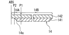
以下、図2ないし図4を参照して、主磁極層14の形状について詳しく説明する。図2は主磁極層14の斜視図、図3は主磁極層14の断面図、図4は主磁極層14の形状を説明するための説明図である。なお、図3は、媒体対向面ABSおよび基板1の面に垂直な断面を示している。また、図4において、(a)は主磁極層14の媒体対向面ABSの近傍の部分の上面を表わし、(b)は主磁極層14の媒体対向面ABSの近傍の部分の断面を表わしている。
【0052】
主磁極層14は、媒体対向面ABSから所定の距離だけ離れた第1の位置P1よりも媒体対向面ABSに近い領域に配置された第1の部分14Aと、第1の位置P1よりも媒体対向面ABSから遠い領域に配置され、第1の部分14Aの幅よりも大きな幅を有する第2の部分14Bとを有している。第1の部分14Aの幅は、媒体対向面ABSからの距離によっては変化しない。第2の部分14Bの幅は、第1の位置P1では第1の部分14Aの幅と等しく、媒体対向面ABSから離れるに従って、徐々に大きくなった後、一定の大きさになっている。
【0053】
第1の部分14Aおよび第2の部分14Bの上面は実質的に平坦になっている。第1の位置P1と媒体対向面ABSとの間に配置された第2の位置P2よりも媒体対向面ABSに近い領域では、第1の部分14Aの底面は、第1の部分14Aの上面に平行になっている。従って、第2の位置P2よりも媒体対向面ABSに近い領域では、第1の部分14Aは一定の厚みD1を有している。
【0054】
一方、第2の位置P2よりも媒体対向面ABSから遠い領域における第1の部分14Aの底面は、第2の位置P2よりも媒体対向面ABSに近い領域における第1の部分14Aの底面よりも、第1の部分14Aの上面から離れている。従って、第2の位置P2よりも媒体対向面ABSから遠い領域では、第1の部分14Aは、D1よりも大きい厚みを有している。
【0055】
また、第1の部分14Aの底面は、第2の位置P2よりも媒体対向面ABSから遠い領域において、媒体対向面ABSから離れるに従って第1の部分14Aの上面から離れるように傾斜した斜面14aを含んでいる。斜面14aと第1の部分14Aの上面とのなす角度θは、25°以上、90°未満であることが好ましい。なお、図4(b)では、第1の部分14Aの底面のうちの第2の位置P2よりも媒体対向面ABSに近い部分と斜面14aとのなす角度をθで表わしている。この角度は、斜面14aと第1の部分14Aの上面とのなす角度と等しい。
【0056】
第2の部分14Bの底面は、斜面14aにおける媒体対向面ABSから遠い端部に接続されている。第2の部分14Bの厚みは、第2の部分14Bの周縁部を除いて一定である。ヨーク層13は、主磁極層14の第2の部分14Bの底面に接している。
【0057】
また、主磁極層14は、ギャップ層9(絶縁層9C)に接する第1層141と、この第1層141に積層された第2層142とを有している。第1層141の媒体対向面ABS側の端部は、第2の位置P2に配置されている。第2層142は、媒体対向面ABSに露出する端面を有している。
【0058】
第2層142の飽和磁束密度は、第1層141の飽和磁束密度よりも大きいことが好ましい。第1層141の材料は、例えば鉄−ニッケル系合金すなわちパーマロイでもよいし、後述するような高飽和磁束密度材でもよい。第2層142の材料としては、飽和磁束密度が1.4T以上の高飽和磁束密度材を用いるのが好ましい。高飽和磁束密度材としては、鉄および窒素原子を含む材料、鉄、ジルコニアおよび酸素原子を含む材料、鉄およびニッケル元素を含む材料等を用いることができる。具体的には、高飽和磁束密度材としては、例えば、NiFe(Ni:45重量%,Fe:55重量%)、FeNやその化合物、Co系アモルファス合金、Fe−Co、Fe−M(必要に応じてO(酸素原子)も含む。)、Fe−Co−M(必要に応じてO(酸素原子)も含む。)の中のうちの少なくとも1種類を用いることができる。ここで、Mは、Ni,N,C,B,Si,Al,Ti,Zr,Hf,Mo,Ta,Nb,Cu(いずれも化学記号)の中から選択された少なくとも1種類である。
【0059】
また、媒体対向面ABSにおける主磁極層14の厚みは、0.05μm以上、0.3μm以下であることが好ましい。
【0060】
また、媒体対向面ABSに露出する主磁極層14の面の形状は、ギャップ層9側の辺が反対側の辺よりも小さい台形形状であることが好ましい。媒体対向面ABSに露出する主磁極層14の面におけるギャップ層9とは反対側の辺の長さは、トラック幅を規定する。トラック幅は、0.05μm以上、0.25μm以下であることが好ましく、0.08μm以上、0.16μm以下であることがより好ましい。
【0061】
次に、本実施の形態に係る磁気ヘッドの作用について説明する。この磁気ヘッドでは、記録ヘッドによって記録媒体に情報を記録し、再生ヘッドによって、記録媒体に記録されている情報を再生する。記録ヘッドにおいて、薄膜コイル10は、記録媒体に記録する情報に応じた磁界を発生する。補助磁極層8、主磁極層14およびヨーク層13は、薄膜コイル10が発生する磁界に対応した磁束を通過させる磁路を形成する。主磁極層14は、薄膜コイル10によって発生された磁界に対応する磁束を通過させると共に、垂直磁気記録方式によって情報を記録媒体に記録するための記録磁界を発生する。
【0062】
次に、本実施の形態に係る磁気ヘッドの製造方法について説明する。まず、基板1の上に絶縁層2を形成する。次に、絶縁層2の上に下部シールド層3を形成する。次に、下部シールド層3の上に、絶縁層4の一部となる絶縁膜を形成し、この絶縁膜の上にMR素子5と、このMR素子5に接続される図示しないリードとを形成する。次に、MR素子5およびリードを、絶縁層4の他の一部となる新たな絶縁膜で覆い、MR素子5およびリードを絶縁層4内に埋設する。
【0063】
次に、絶縁層4の上に上部シールド層6を形成し、その上に非磁性層7を形成する。次に、この非磁性層7の上に、補助磁極層8を所定の形状に形成する。次に、図示しないが、非磁性層7および補助磁極層8をアルミナ等の非磁性材料で覆い、補助磁極層8が露出するまで非磁性材料を研磨して、補助磁極層8の上面を平坦化する。なお、非磁性層7を設けずに、上部シールド層6および補助磁極層8の代わりに、これらを兼ねた1つの磁性層を設けてもよい。
【0064】
次に、補助磁極層8の上に、アルミナ等の非導電性且つ非磁性の材料をスパッタして、絶縁層9Aを形成する。次に、周知のフォトリソグラフィ技術とドライエッチング技術とを用いて、補助磁極層8とヨーク層13とを連結すべき位置において、絶縁層9Aにコンタクトホール9aを形成する。
【0065】
次に、周知のフォトリソグラフィ技術および成膜技術(例えば電気めっき法)を用いて、絶縁層9Aの上に薄膜コイル10を形成する。
【0066】
次に、周知のフォトリソグラフィ技術を用いて、少なくとも薄膜コイル10の巻線間に充填される絶縁層9Bを形成する。ここでは、絶縁層9Bは薄膜コイル10を完全に覆うように形成しているが、薄膜コイル10の巻線間に充填される絶縁層9Bを形成した後に、絶縁層9Bとは別に、薄膜コイル10および絶縁層9Bを覆う絶縁層を形成してもよい。
【0067】
次に、周知のフォトリソグラフィ技術および成膜技術(例えば電気めっき法)を用いて、コンタクトホール9aが形成された位置から媒体対向面ABSに向けて所定の位置まで、補助磁極層8および絶縁層9Bの上にヨーク層13を形成する。
【0068】
次に、スパッタ法を用いて、絶縁層9A、絶縁層9Bおよびヨーク層13を覆うように絶縁層9Cを形成する。次に、例えば化学機械研磨を用いて、ヨーク層13が露出するまで絶縁層9Cの表面を研磨して、絶縁層9Cおよびヨーク層13の上面を平坦化する。
【0069】
次に、絶縁層9Cおよびヨーク層13の上に、主磁極層14を形成する。主磁極層14の形成方法については、後で詳しく説明する。次に、主磁極層14の周囲に絶縁層17を形成する。次に、主磁極層14を覆うように保護層18を形成する。なお、主磁極層14の形成後、保護層18を形成する前に、主磁極層14の上に絶縁層を介して記録シールド層を形成することが好ましい。次に、保護層18の上に配線や端子等を形成し、スライダ単位で基板を切断し、媒体対向面ABSの研磨、浮上用レールの作製等を行って、磁気ヘッドが完成する。
【0070】
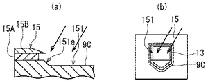
次に、図5ないし図12を参照して、主磁極層14の形成方法について説明する。図5ないし図12において、(a)は媒体対向面および基板の面に垂直な断面を示し、(b)は積層体の上面を示している。主磁極層14の形成方法では、まず、図5に示したように、平坦化された絶縁層9Cおよびヨーク層13の上面の上に、マスク15を形成する。マスク15は、主磁極層14の第1層141を配置すべき位置に開口部を有している。また、マスク15は、底面が上面よりも小さくなるようにアンダーカットを有している。このようなマスク15は、例えば積層された2つの有機膜15A,15Bからなるレジスト層をパターニングすることによって形成される。
【0071】
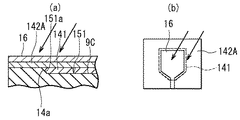
次に、図6に示したように、マスク15を用いて絶縁層9Cおよびヨーク層13を選択的にエッチングして、第1層141を配置すべき凹部151を形成する。このとき、凹部151の媒体対向面ABS側(図6(a)における左側)の端面151aを、深くなるに従って媒体対向面ABSから離れるように傾斜した斜面とする。凹部151を形成するためのエッチングには、例えばイオンミリングが用いられる。この場合には、例えば、イオンビームの進行方向が凹部151の形成前における絶縁層9Cおよびヨーク層13の上面に垂直な方向に対して0〜20°の角度をなすようにする。図6中の矢印は、イオンビームを表わしている。なお、イオンミリングの代わりに、反応性イオンエッチングを用いてもよい。
【0072】
次に、図7に示したように、マスク15を用いてスパッタ法によって凹部151内に第1層141を形成する。このとき、凹部151の端面151aによって、主磁極層14における斜面14aが形成される。次に、図8に示したように、マスク15をリフトオフする。
【0073】
次に、図9に示したように、第1層141および絶縁層9Cの上に、スパッタ法によって、磁性材料よりなる磁性層142Aを形成する。磁性層142Aは、第2層142を形成するための層であり、本発明における被パターニング層に対応する。
【0074】
次に、図10に示したように、磁性層142Aの上に、磁性層142Aをパターニングするためのエッチングマスク16を形成する。エッチングマスク16は、形成しようとする第2層142に対応した形状を有している。また、エッチングマスク16のうち、第1層141の上方に配置される部分の大きさは、第1層141よりも若干小さくなっている。エッチングマスク16は、例えば金属材料によって形成される。このようなエッチングマスク16は、例えば、スパッタ法によって形成された膜を選択的にエッチングすることによって形成することができる。
【0075】
次に、図11に示したように、エッチングマスク16を用いて、磁性層142A、第1層141、絶縁層9Cの一部およびヨーク層13の一部を選択的にエッチングする。このエッチングには、例えばイオンミリングが用いられる。図11中の矢印は、イオンビームを表わしている。なお、イオンミリングの代わりに、反応性イオンエッチングを用いてもよい。
【0076】
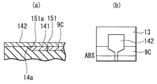
図12に示したように、エッチングによってパターニングされた磁性層142Aは第2層142となる。また、上記エッチング工程において、第1層141の周縁部がエッチングされて、第1層141がパターニングされる。なお、図12(b)には、後に媒体対向面ABSが形成される位置を破線で示している。
【0077】
次に、図示しないが積層体の上面を覆うように絶縁層17を形成する。次に、例えば化学機械研磨を用いて、第2層142が露出するまで絶縁層17の表面を研磨して、図1に示したように、絶縁層17および第2層142の上面を平坦化する。
【0078】
上述のように、本実施の形態では、1つのエッチングマスク16を用いて、磁性層142Aおよび第1層141をエッチングすることによって、第1層141および第2層142をパターニングしている。そのため、本実施の形態では、第1層141と第2層142との位置合わせを正確に行うことができる。本実施の形態では、主磁極層14は、トラック幅を規定する第1の部分14Aにおいて、厚みが変化している。そのため、磁気ヘッドにおける記録特性を劣化させないためには、第1の部分14Aを正確に形成することが重要である。本実施の形態によれば、上述のように、第1層141と第2層142との位置合わせを正確に行うことができることから、第1の部分14Aを正確に形成することができる。従って、本実施の形態によれば、良好な記録特性を実現することができる。
【0079】
なお、第1層141の形成後、第2層142を形成する前に、第1層141および絶縁層9Cの上面を研磨によって平坦化してもよい。この研磨は、第1層141の上面と絶縁層9Cの上面との間に発生するわずかな段差を解消するためのものである。そのため、この研磨では、必要以上に絶縁層9Cの上面を研磨することはない。従って、この研磨によって、第1層141の媒体対向面側の端部の位置は、ほとんど変化しない。
【0080】
また、本実施の形態では、第2層142の上面を平坦化することにより、媒体対向面ABSにおいて、主磁極層14のギャップ層9とは反対側の端部を平坦化することができる。これにより、媒体対向面ABSにおいて主磁極層14より発生される磁界を、トラックに交差する方向について均一化することができ、その結果、記録媒体におけるビットパターン形状の歪みを抑えて、線記録密度を向上させることができる。
【0081】
媒体対向面に露出する主磁極層14の面の形状を、ギャップ層9側の辺が反対側の辺よりも小さい台形形状とする場合には、例えば、イオンビームの進行方向が第2層142の上面に垂直な方向に対して傾くようにイオンミリングを行って、第2層142をパターニングする。
【0082】
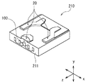
以下、本実施の形態に係るヘッドジンバルアセンブリおよびハードディスク装置について説明する。まず、図13を参照して、ヘッドジンバルアセンブリに含まれるスライダ210について説明する。ハードディスク装置において、スライダ210は、回転駆動される円盤状の記録媒体であるハードディスクに対向するように配置される。このスライダ210は、主に図1における基板1および保護層18からなる基体211を備えている。基体211は、ほぼ六面体形状をなしている。基体211の六面のうちの一面は、ハードディスクに対向するようになっている。この一面には、媒体対向面となるエアベアリング面20が形成されている。ハードディスクが図13におけるz方向に回転すると、ハードディスクとスライダ210との間を通過する空気流によって、スライダ210に、図13におけるy方向の下方に揚力が生じる。スライダ210は、この揚力によってハードディスクの表面から浮上するようになっている。なお、図13におけるx方向は、ハードディスクのトラック横断方向である。スライダ210の空気流出側の端部(図13における左下の端部)の近傍には、本実施の形態に係る磁気ヘッド100が形成されている。
【0083】
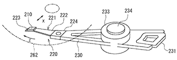
次に、図14を参照して、本実施の形態に係るヘッドジンバルアセンブリ220について説明する。ヘッドジンバルアセンブリ220は、スライダ210と、このスライダ210を弾性的に支持するサスペンション221とを備えている。サスペンション221は、例えばステンレス鋼によって形成された板ばね状のロードビーム222、このロードビーム222の一端部に設けられると共にスライダ210が接合され、スライダ210に適度な自由度を与えるフレクシャ223と、ロードビーム222の他端部に設けられたベースプレート224とを有している。ベースプレート224は、スライダ210をハードディスク262のトラック横断方向xに移動させるためのアクチュエータのアーム230に取り付けられるようになっている。アクチュエータは、アーム230と、このアーム230を駆動するボイスコイルモータとを有している。フレクシャ223において、スライダ210が取り付けられる部分には、スライダ210の姿勢を一定に保つためのジンバル部が設けられている。
【0084】
ヘッドジンバルアセンブリ220は、アクチュエータのアーム230に取り付けられる。1つのアーム230にヘッドジンバルアセンブリ220を取り付けたものはヘッドアームアセンブリと呼ばれる。また、複数のアームを有するキャリッジの各アームにヘッドジンバルアセンブリ220を取り付けたものはヘッドスタックアセンブリと呼ばれる。
【0085】
図14は、ヘッドアームアセンブリの一例を示している。このヘッドアームアセンブリでは、アーム230の一端部にヘッドジンバルアセンブリ220が取り付けられている。アーム230の他端部には、ボイスコイルモータの一部となるコイル231が取り付けられている。アーム230の中間部には、アーム230を回動自在に支持するための軸234に取り付けられる軸受け部233が設けられている。
【0086】
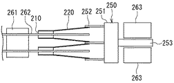
次に、図15および図16を参照して、ヘッドスタックアセンブリの一例と本実施の形態に係るハードディスク装置について説明する。図15はハードディスク装置の要部を示す説明図、図16はハードディスク装置の平面図である。ヘッドスタックアセンブリ250は、複数のアーム252を有するキャリッジ251を有している。複数のアーム252には、複数のヘッドジンバルアセンブリ220が、互いに間隔を開けて垂直方向に並ぶように取り付けられている。キャリッジ251においてアーム252とは反対側には、ボイスコイルモータの一部となるコイル253が取り付けられている。ヘッドスタックアセンブリ250は、ハードディスク装置に組み込まれる。ハードディスク装置は、スピンドルモータ261に取り付けられた複数枚のハードディスク262を有している。各ハードディスク262毎に、ハードディスク262を挟んで対向するように2つのスライダ210が配置される。また、ボイスコイルモータは、ヘッドスタックアセンブリ250のコイル253を挟んで対向する位置に配置された永久磁石263を有している。
【0087】
スライダ210を除くヘッドスタックアセンブリ250およびアクチュエータは、本発明における位置決め装置に対応し、スライダ210を支持すると共にハードディスク262に対して位置決めする。
【0088】
本実施の形態に係るハードディスク装置では、アクチュエータによって、スライダ210をハードディスク262のトラック横断方向に移動させて、スライダ210をハードディスク262に対して位置決めする。スライダ210に含まれる磁気ヘッド100は、記録ヘッドによって、ハードディスク262に情報を記録し、再生ヘッドによって、ハードディスク262に記録されている情報を再生する。
【0089】
次に、本実施の形態における主磁極層14の形状に基づく効果を確認するために行った第1のシミュレーションについて説明する。この第1のシミュレーションでは、本実施の形態における主磁極層14のモデルと、2つの比較例における主磁極層のモデルとについて、主磁極層14より発生される記録磁界の垂直成分を求めた。図17は第1の比較例における主磁極層114の形状を表し、図18は第2の比較例における主磁極層124の形状を表している。なお、図17および図18において、(a)は主磁極層114,124の媒体対向面ABSの近傍の部分の上面を表わし、(b)は主磁極層114,124の媒体対向面ABSの近傍の部分の断面を表わしている。
【0090】
図17に示した第1の比較例における主磁極層114は、第1の部分114Aおよび第2の部分114Bを有している。第1の部分114Aおよび第2の部分114Bの平面形状は、本実施の形態における主磁極層14の第1の部分14Aおよび第2の部分14Bと同様である。しかし、第1の比較例では、本実施の形態とは異なり、主磁極層114の上面と底面は共に平坦で、主磁極層114の厚みは位置によらず一定である。第1のシミュレーションでは、主磁極層114の厚みを0.2μmとしている。
【0091】
図18に示した第2の比較例における主磁極層124は、第1の部分124Aおよび第2の部分124Bを有している。第1の部分124Aおよび第2の部分124Bの平面形状は、本実施の形態における主磁極層14の第1の部分14Aおよび第2の部分14Bと同様である。また、主磁極層124の上面は平坦である。しかし、第2の比較例では、本実施の形態とは異なり、第1の部分124Aの厚みは、位置によらず一定である。また、第2の部分124Bの底面は、第1の位置P1よりも媒体対向面ABSから遠い領域において、媒体対向面ABSから離れるに従って第2の部分124Bの上面から離れるように傾斜した斜面124aを含んでいる。第1のシミュレーションでは、斜面124aと第1の部分124Aの上面とのなす角度θ2を45°としている。また、第1の位置P1は、媒体対向面ABSから0.3μm離れた位置としている。また、第1の部分124Aの厚みは0.2μmとし、第2の部分124Bの最大の厚みは0.3μmとしている。
【0092】
また、第1のシミュレーションでは、本実施の形態における主磁極層14の斜面14aと第1の部分14Aの上面とのなす角度θを45°としている。また、第1の位置P1は、媒体対向面ABSから0.3μm離れた位置とし、第2の位置P2は、媒体対向面ABSから0.1μm離れた位置としている。また、第1の部分14Aの厚みは0.2μmとし、第2の部分14Bの最大の厚みは0.3μmとしている。
【0093】
上記の3つのモデルについて、主磁極層14より発生される記録磁界の垂直成分を求めた結果を図19に示す。図19において、横軸は記録媒体進行方向について位置を示し、縦軸は記録磁界の垂直成分を示している。なお、横軸における位置は、非磁性層7と補助磁極層8との境界位置からの距離で表している。
【0094】
また、図19において、符号30は本実施の形態におけるモデルの特性を表し、符号31は第1の比較例におけるモデルの特性を表し、符号32は第2の比較例におけるモデルの特性を表している。記録磁界の垂直成分の最大値は、本実施の形態におけるモデルでは11393[Oe=×79.6A/m]、第1の比較例におけるモデルでは10184[Oe=×79.6A/m]、第2の比較例におけるモデルでは10562[Oe=×79.6A/m]であった。
【0095】
この結果から分かるように、本実施の形態によれば、主磁極層の厚みが変化しない第1の比較例に比べて、記録磁界の垂直成分の最大値を1200[Oe]以上大きくすることができる。また、本実施の形態によれば、主磁極層の厚みが大きくなり始める位置が主磁極層の幅が大きくなり始める位置と一致する第2の比較例に比べて、記録磁界の垂直成分の最大値を800[Oe]以上大きくすることができる。また、この第1のシミュレーションとは別に行った実験から、シミュレーションにおける記録磁界の垂直成分の最大値が1000[Oe]大きくなると、記録ヘッドのオーバーライト特性が約5dB向上することが分かっている。このことから、本実施の形態によれば、第1の比較例に比べて6dB以上、第2の比較例に比べて4dB以上のオーバーライト特性の向上が期待できる。
【0096】
次に、主磁極層14における斜面14aと第1の部分14Aの上面とのなす角度θの大きさと磁気ヘッドの記録特性との関係を調べた第2のシミュレーションの結果について説明する。この第2のシミュレーションに先立ち、実験により、凹部151を形成するためのエッチングの条件と、凹部151の端面151aの状態との関係を調べた。この実験では、まず、イオンミリングを用いて凹部151を形成した。その際のイオンビームの進行方向と凹部151の形成前における絶縁層9Cおよびヨーク層13の上面に垂直な方向とのなす角度(以下、イオンビーム角度と言う。)は、0°,10°,15°,20°の4通りとした。そして、実験では、この4通りの条件で形成された凹部151について、端面151aと凹部151の形成前における絶縁層9Cの上面とのなす角度(以下、端面角度と言う。)を測定した。イオンビーム角度と端面角度との関係は、以下のようになった。すなわち、イオンビーム角度が0°,10°,15°,20°の場合における端面角度は、それぞれ、58.9°,42.6°,35°,24.8°となった。また、実験では、反応性イオンエッチングを用いて凹部151を形成した。そのときの端面角度は、82.5°となった。
【0097】
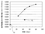
次に、第2のシミュレーションにより、上記端面角度と記録磁界の垂直成分の最大値との対応関係を求めた。その結果を、図20に示す。図20において、横軸は端面角度を示し、縦軸は記録磁界の垂直成分の最大値を示している。なお、図20において、符号41で示した点は、図17に示した第1のモデルにおける値を表している。また、符号42で示した点は、図18に示した第2のモデルにおける値を表している。図20におけるその他の4つの点は、それぞれ、本実施の形態のモデルにおいて端面角度を、24.8°,42.6°,58.9°,82.5°とした場合の値を表している。第2のシミュレーションにおけるその他の条件は、第1のシミュレーションと同様である。
【0098】
図20に示した結果から、端面角度を大きくすることによって記録磁界の垂直成分の最大値を大きくすることができることが分かる。図20に示した結果から、端面角度が約25°以上であれば、第1および第2の比較例よりも、記録磁界の垂直成分を大きくすることができることが分かる。一方、端面角度が90°以上になると、主磁極層14の底面にできるエッジの角度が鋭角となり、このエッジから磁束の漏れが生じやすくなる。従って、端面角度は、25°以上、90°未満であることが好ましい。また、図20に示した結果から、端面角度が約40°以上であれば、第1の比較例に比べて、記録磁界の垂直成分の最大値を1000[Oe]以上大きくでき、記録ヘッドのオーバーライト特性を5dB以上向上できると考えられる。そこで、端面角度は、40°以上、90°未満であることがより好ましい。
【0099】
次に、図21ないし図23を参照して、本実施の形態において、媒体対向面ABSにおける主磁極層14の厚みが0.05μm以上、0.3μm以下であることが好ましいことを示す2つの実験結果について説明する。なお、以下の説明では、媒体対向面ABSにおける主磁極層14の厚みを、主磁極厚みと呼び、記号PTで表わす。
【0100】
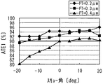
第1の実験では、主磁極厚みPTと、スキュー角と、サイドイレーズ抑制特性との関係を調べた。なお、サイドイレーズとは、あるトラックへの情報の書き込み時に隣接トラックの情報が消去される現象を言う。サイドイレーズ抑制特性は、このサイドイレーズを抑制できる性能を表わす。第1の実験では、それぞれ主磁極厚みPTが0.2μm、0.3μm、0.4μmの3つの磁気ヘッドを作製した。これらの磁気ヘッドにおいて、媒体対向面ABSに露出する主磁極層14の面におけるギャップ層9とは反対側の辺の長さ(以下、磁極幅と言う。)は0.18μmである。
【0101】
サイドイレーズ抑制特性は、以下のようにして測定した。まず、隣り合う3つのトラックに、それぞれ、周波数249MHzの信号、周波数250MHzの信号、周波数249MHzの信号を用いて情報の書き込みを行う。次に、外周側のトラックより情報を読み込み、得られた再生信号のうちの周波数249MHzの成分の大きさをTAA1とする。また、内周側のトラックより情報を読み込み、得られた再生信号のうちの周波数249MHzの成分の大きさをTAA2とする。次に、中央のトラックに、周波数250MHzの信号を用いて情報の書き込みを100回行う。次に、外周側のトラックより情報を読み込み、得られた再生信号のうちの周波数249MHzの成分の大きさをTAA3とする。また、内周側のトラックより情報を読み込み、得られた再生信号のうちの周波数249MHzの成分の大きさをTAA4とする。そして、下記の2つの式により、外周側のトラックに関するサイドイレーズ抑制特性ATE1と、内周側のトラックに関するサイドイレーズ抑制特性ATE2とを求める。
【0102】
ATE1(%)=(TAA3/TAA1)×100
ATE2(%)=(TAA4/TAA2)×100
【0103】
また、ここでは、スキュー角が0°となる位置よりも磁気ヘッドが内周側の位置にあるときに発生するスキュー角を負の値で表わし、スキュー角が0°となる位置よりも磁気ヘッドが外周側の位置にあるときに発生するスキュー角を正の値で表わす。
【0104】
第1の実験では、3つの磁気ヘッドのそれぞれについて、スキュー角を変えて、サイドイレーズ抑制特性ATE1,ATE2を測定し、主磁極厚みPTと、スキュー角と、サイドイレーズ抑制特性ATE1,ATE2との関係を求めた。
【0105】
主磁極厚みPTと、スキュー角と、サイドイレーズ抑制特性ATE1との関係を、下記の表および図21に示す。下記の表において、「PT=0.2μm」、「PT=0.3μm」、「PT=0.4μm」の各項目の下の欄中の数字が、それぞれ、主磁極厚みPTが0.2μm、0.3μm、0.4μmのときのサイドイレーズ抑制特性ATE1(%)を表わしている。
【0106】
【表1】

また、主磁極厚みPTと、スキュー角と、サイドイレーズ抑制特性ATE2との関係を、下記の表および図22に示す。下記の表において、「PT=0.2μm」、「PT=0.3μm」、「PT=0.4μm」の各項目の下の欄中の数字が、それぞれ、主磁極厚みPTが0.2μm、0.3μm、0.4μmのときのサイドイレーズ抑制特性ATE2(%)を表わしている。
【0108】
【表2】
サイドイレーズ抑制特性ATE1、ATE2は、値が大きいほど、サイドイレーズが抑制されていることを表わす。サイドイレーズ抑制特性ATE1、ATE2は、いずれも90%以上であることが好ましい。上記の2つの表と図21および図22から、主磁極厚みPTが0.3μm以下であれば、スキュー角が−20(deg)近傍あるいは20(deg)近傍のときを除いて、サイドイレーズ抑制特性ATE1、ATE2が、いずれも90%以上となることが分かる。従って、主磁極厚みPTは0.3μm以下であることが好ましい。
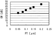
【0110】
次に、第2の実験について説明する。第2の実験では、主磁極厚みPTと、オーバーライト特性OWとの関係を調べた。第2の実験では、主磁極厚みPTが0.20μm、0.15μm、0.13μm、0.10μm、0.08μm、0.05μmの6つの磁気ヘッドを作製した。これらの磁気ヘッドにおいて、磁極幅は0.12μm、媒体対向面ABSと第1の位置P1との間の距離は0.3μm、媒体対向面ABSと第2の位置P2との間の距離は0.2μm、斜面14aと第1の部分14Aの上面とのなす角度θは45°である。
【0111】
オーバーライト特性OWは、以下のようにして測定した。まず、所定のトラックに、周波数300MHzの信号を用いて情報の書き込みを行う。次に、そのトラックより情報を読み込み、得られた再生信号のうちの周波数300MHzの成分の大きさをTAA5とする。次に、同一トラックに、周波数50MHzの信号を用いて情報の重ね書きを行う。次に、そのトラックより情報を読み込み、得られた再生信号のうちの周波数300MHzの成分の大きさをTAA6とする。そして、下記の式により、オーバーライト特性OWを求める。
【0112】
OW(dB)=−20log10(TAA6/TAA5)
【0113】
主磁極厚みPTとオーバーライト特性OWとの関係を、下記の表および図23に示す。なお、下記の表には、記録磁界の垂直成分(Oe=×79.6A/m)も合わせて記載している。
【0114】
【表3】
オーバーライト特性OWは、値が大きいほど、重ね書きの性能が高いことを表わす。オーバーライト特性OWは、最低でも25dBは必要であり、30dB以上であることが好ましい。上記の表と図23から分かるように、オーバーライト特性OWを25dB以上とするには、主磁極厚みPTは0.05μm以上とする必要がある。
【0116】
以上の2つの実験から分かるように、媒体対向面ABSにおける主磁極層14の厚みは、0.05μm以上、0.3μm以下であることが好ましい。
【0117】
以上説明したように、本実施の形態に係る磁気ヘッドでは、主磁極層14の厚みが大きくなり始める第2の位置P2は、主磁極層14の幅が大きくなり始める第1の位置P1と媒体対向面ABSとの間に配置されている。これにより、媒体対向面ABSにおける主磁極層14の厚みを小さくして、隣接トラックへの書き込みを防止しながら、記録磁界強度の減少を抑制することができる。
【0118】
また、本実施の形態において、媒体対向面ABSと第2の位置P2との間の領域では、主磁極層14の第1の部分14Aは、媒体対向面ABSからの距離によっては幅も厚みも変化しない。そのため、磁気ヘッドの製造過程において、研磨によって媒体対向面ABSを形成する際に、研磨終了位置が多少ずれても、媒体対向面ABSにおける主磁極層14の幅や厚みが変化しない。従って、本実施の形態によれば、均質な磁気ヘッドを量産することが可能になる。
【0119】
また、本実施の形態では、主磁極層14の第1の部分14Aにおけるギャップ層9とは反対側の面、すなわち記録媒体の進行方向Tの前側(スライダにおける空気流出端側)の面は実質的に平坦である。これにより、記録媒体の進行方向Tについての記録磁界の垂直成分の変化を急峻にすることができ、その結果、記録密度の向上が可能になる。
【0120】
また、本実施の形態では、主磁極層14は、ギャップ層9に接する第1層141と、第1層141に積層された第2層142とを有している。第1層141は第2の位置P2に配置された媒体対向面ABS側の端部を有し、第2層142は媒体対向面ABSに露出する端面を有している。このように主磁極層14を2つの層141,142によって構成することにより、主磁極層14の形成が容易になる。
【0121】
また、本実施の形態では、第2層142の飽和磁束密度を第1層141の飽和磁束密度よりも大きくしている。これにより、主磁極層14を通過する磁束が、主磁極層14の途中、特に第1の位置P1や第2の位置P2で漏れることを防止して、磁束を効率よく媒体対向面ABS側の端部まで導くことができる。
【0122】
また、本実施の形態では、第1の部分14Aのギャップ層9側の面(底面)は、第2の位置P2よりも媒体対向面ABSから遠い領域において、媒体対向面ABSから離れるに従って、第1の部分14Aのギャップ層9とは反対側の面(上面)から離れるように傾斜した斜面14aを含んでいる。これにより、主磁極層14を通過する磁束が主磁極層14の途中で漏れることを防止しながら、主磁極層14より発生される記録磁界の垂直成分を大きくすることができる。
【0123】
また、本実施の形態では、媒体対向面ABSにおける主磁極層14の厚みを、0.05μm以上、0.3μm以下としている。このように媒体対向面ABSにおける主磁極層14の厚みを小さくすることにより、隣接トラックへの書き込みをより確実に防止することができる。
【0124】
また、本実施の形態において、媒体対向面ABSに露出する主磁極層14の面の形状を、ギャップ層9側の辺が反対側の辺よりも小さい台形形状とした場合には、隣接トラックへの書き込みをより確実に防止することができる。
【0125】
また、本実施の形態では、ヨーク層13は、主磁極層14の第2の部分14Bのギャップ層9側の面に接している。これにより、エッチングによって主磁極層14をパターニングする際に、ヨーク層13がダメージを受けることを防止することができる。
【0126】
また、本実施の形態では、主磁極層14の第1層141を形成する前に、ギャップ層9をエッチングして、ギャップ層9の上面に、第1層141を配置すべき凹部151を形成し、この凹部151内に第1層141を形成している。これにより、主磁極層14の形成がより容易になる。
【0127】
また、本実施の形態では、凹部151を形成する工程において、凹部151の媒体対向面ABS側の端面151aを、深くなるに従って媒体対向面ABSから離れるように傾斜した斜面としている。そして、この端面151aによって、主磁極層14における斜面14aが形成される。これにより、主磁極層14を通過する磁束が主磁極層14の途中で漏れることを防止しながら、主磁極層14より発生される記録磁界の垂直成分を大きくすることができる。
【0128】
また、本実施の形態では、主磁極層14の第1層141を形成する工程と第2層142を形成する工程との間において、ギャップ層9および第1層141の上面を平坦化する工程を含んでいてもよい。この場合には、第1層141の上面とギャップ層9の上面との間に発生するわずかな段差を解消することができ、これにより、主磁極層14を精度よく形成することができる。
【0129】
本実施の形態に係るヘッドジンバルアセンブリおよびハードディスク装置は、前述の本実施の形態に係る磁気ヘッドと同様の効果を奏する。
【0130】
なお、本発明は上記実施の形態に限定されず、種々の変更が可能である。例えば、実施の形態では、基体側に再生ヘッドを形成し、その上に記録ヘッドを積層した構造の磁気ヘッドについて説明したが、この積層順序を逆にしてもよい。
【0131】
【発明の効果】
以上説明したように、請求項1ないし8のいずれかに記載の垂直磁気記録用磁気ヘッドでは、主磁極層の厚みが変化する第2の位置は、主磁極層の幅が変化する第1の位置と媒体対向面との間に配置されている。これにより、本発明によれば、隣接トラックへの書き込みを防止しながら、記録磁界強度の減少を抑制することができるという効果を奏する。また、本発明の垂直磁気記録用磁気ヘッドにおいて、媒体対向面と第2の位置との間の領域では、主磁極層の第1の部分は、媒体対向面からの距離によっては幅も厚みも変化しない。そのため、本発明によれば、磁気ヘッドの製造過程において、研磨によって媒体対向面を形成する際に、研磨終了位置が多少ずれても、媒体対向面における主磁極層の幅や厚みが変化しない。従って、本発明によれば、量産に適した垂直磁気記録用磁気ヘッドを実現することができるという効果を奏する。また、本発明では、主磁極層の第1の部分におけるギャップ層とは反対側の第2面は実質的に平坦である。これにより、本発明によれば、記録媒体の進行方向についての記録磁界の垂直成分の変化を急峻にすることができ、その結果、記録密度の向上が可能になるという効果を奏する。
【0132】
また、請求項2または3記載の垂直磁気記録用磁気ヘッドでは、主磁極層は、ギャップ層に接する第1層と、第1層に積層された第2層とを有し、第1層は第2の位置に配置された媒体対向面側の端部を有し、第2層は媒体対向面に露出する端面を有している。これにより、本発明によれば、主磁極層の形成が容易になるという効果を奏する。
【0133】
また、請求項3記載の垂直磁気記録用磁気ヘッドでは、第2層の飽和磁束密度を第1層の飽和磁束密度よりも大きくしている。これにより、本発明によれば、主磁極層を通過する磁束が主磁極層の途中で漏れることを防止して、磁束を効率よく媒体対向面側の端部まで導くことができるという効果を奏する。
【0134】
また、請求項4または5記載の垂直磁気記録用磁気ヘッドでは、主磁極層の第1の部分の第1面は、第2の位置よりも媒体対向面から遠い領域において、媒体対向面から離れるに従って第2面から離れるように傾斜した斜面を含んでいる。これにより、本発明によれば、主磁極層を通過する磁束が主磁極層の途中で漏れることを防止しながら、主磁極層より発生される記録磁界の垂直成分を大きくすることができるという効果を奏する。
【0135】
また、請求項6記載の垂直磁気記録用磁気ヘッドでは、媒体対向面における主磁極層の厚みを、0.05μm以上、0.3μm以下としている。これにより、本発明によれば、隣接トラックへの書き込みをより確実に防止することができるという効果を奏する。
【0136】
また、請求項7記載の垂直磁気記録用磁気ヘッドでは、媒体対向面に露出する主磁極層の面の形状を、ギャップ層側の辺が反対側の辺よりも小さい台形形状としている。これにより、本発明によれば、隣接トラックへの書き込みをより確実に防止することができるという効果を奏する。
【0137】
また、請求項8記載の垂直磁気記録用磁気ヘッドでは、ヨーク層は、主磁極層の第2の部分のギャップ層側の面に接している。これにより、本発明によれば、主磁極層のパターニングによってヨーク層がダメージを受けることを防止することができるという効果を奏する。
【0138】
請求項9ないし17のいずれかに記載の垂直磁気記録用磁気ヘッドの製造方法によれば、本発明の垂直磁気記録用磁気ヘッドの効果と同様に、隣接トラックへの書き込みを防止しながら記録磁界強度の減少を抑制することができ、量産に適した垂直磁気記録用磁気ヘッドを実現することができるという効果を奏する。また、本発明の製造方法によれば、更に、記録媒体の進行方向についての記録磁界の垂直成分の変化を急峻にすることができ、その結果、記録密度の向上が可能になるという効果を奏する。また、本発明では、主磁極層を形成する工程は、第2の位置に配置された媒体対向面側の端部を有すると共にギャップ層に接する第1層を形成する工程と、第1層の上に、媒体対向面に露出する端面を有する第2層を形成する工程とを含んでいる。これにより、本発明によれば、主磁極層の形成が容易になるという効果を奏する。
【0139】
また、請求項10ないし14のいずれかに記載の垂直磁気記録用磁気ヘッドの製造方法では、主磁極層を形成する工程は、第1層を形成する工程の前に、ギャップ層をエッチングして、ギャップ層の上面に、第1層を配置すべき凹部を形成する工程を含み、第1層を形成する工程は、凹部内に第1層を形成する。これにより、本発明によれば、主磁極層の形成がより容易になるという効果を奏する。
【0140】
また、請求項11記載の垂直磁気記録用磁気ヘッドの製造方法では、凹部を形成する工程において、凹部の媒体対向面側の端面を、深くなるに従って媒体対向面から離れるように傾斜した斜面とする。これにより、本発明によれば、主磁極層を通過する磁束が主磁極層の途中で漏れることを防止しながら、主磁極層より発生される記録磁界の垂直成分を大きくすることができるという効果を奏する。
【0141】
また、請求項15記載の垂直磁気記録用磁気ヘッドの製造方法では、第2層を形成する工程は、第1層の上に、第2層を形成するための被パターニング層を形成する工程と、被パターニング層の上に、被パターニング層をパターニングするためのエッチングマスクを形成する工程と、エッチングマスクを用いて、被パターニング層および第1層を選択的にエッチングする工程とを含んでいる。そして、エッチングする工程において、被パターニング層がパターニングされることによって第2層が形成され、且つ第1層がパターニングされる。本発明によれば、第1層と第2層との位置合わせを正確を行うことができ、その結果、良好な記録特性を実現することができるという効果を奏する。
【0142】
また、請求項16記載の垂直磁気記録用磁気ヘッドの製造方法では、主磁極層を形成する工程は、第1層を形成する工程と第2層を形成する工程との間において、ギャップ層および第1層の上面を平坦化する工程を含んでいる。これにより、本発明によれば、第1層の上面とギャップ層の上面との間に発生するわずかな段差を解消することができ、その結果、主磁極層を精度よく形成することができるという効果を奏する。
【0143】
また、請求項17記載の垂直磁気記録用磁気ヘッドの製造方法では、主磁極層を形成する工程は、第2層を形成した後に、第2層の上面を平坦化する工程を含んでいる。これにより、本発明によれば、媒体対向面において、主磁極層のギャップ層とは反対側の端部を平坦化することができる。これにより、媒体対向面において主磁極層より発生される磁界を、トラックに交差する方向について均一化することができ、その結果、記録媒体におけるビットパターン形状の歪みを抑えて、線記録密度を向上させることができるという効果を奏する。
【0144】
また、請求項18記載のヘッドジンバルアセンブリまたは請求項19記載のハードディスク装置によれば、前述の本発明の垂直磁気記録用磁気ヘッドと同様の効果を奏する。
【図面の簡単な説明】
【図1】本発明の一実施の形態に係る垂直磁気記録用磁気ヘッドの構成を示す断面図である。
【図2】本発明の一実施の形態における主磁極層の斜視図である。
【図3】本発明の一実施の形態における主磁極層の断面図である。
【図4】本発明の一実施の形態における主磁極層の形状を説明するための説明図である。
【図5】本発明の一実施の形態における主磁極層の形状方法を説明するための説明図である。
【図6】図5に示した工程に続く工程を示す説明図である。
【図7】図6に示した工程に続く工程を示す説明図である。
【図8】図7に示した工程に続く工程を示す説明図である。
【図9】図8に示した工程に続く工程を示す説明図である。
【図10】図9に示した工程に続く工程を示す説明図である。
【図11】図10に示した工程に続く工程を示す説明図である。
【図12】図11に示した工程に続く工程を示す説明図である。
【図13】本発明の一実施の形態に係るヘッドジンバルアセンブリに含まれるスライダを示す斜視図である。
【図14】本発明の一実施の形態に係るヘッドジンバルアセンブリを含むヘッドアームアセンブリを示す斜視図である。
【図15】本発明の一実施の形態に係るハードディスク装置の要部を示す説明図である。
【図16】本発明の一実施の形態に係るハードディスク装置の平面図である。
【図17】第1の比較例における主磁極層の形状を示す説明図である。
【図18】第2の比較例における主磁極層の形状を示す説明図である。
【図19】主磁極層より発生される記録磁界の垂直成分を求めたシミュレーションの結果を示す特性図である。
【図20】主磁極層における端面角度と記録磁界の垂直成分の最大値との対応関係を求めたシミュレーションの結果を示す特性図である。
【図21】本発明の一実施の形態に関わる第1の実験の結果を示す特性図である。
【図22】本発明の一実施の形態に関わる第1の実験の結果を示す他の特性図である。
【図23】本発明の一実施の形態に関わる第2の実験の結果を示す他の特性図である。
【符号の説明】
3…下部シールド層、4…絶縁層、5…MR素子、6…上部シールド層、7…非磁性層、8…補助磁極層、9…ギャップ層、9A,9B,9C…絶縁層、10…薄膜コイル、13…ヨーク層、14…主磁極層、14A…第1の部分、14B…第2の部分、141…第1層、142…第2層。[0001]
TECHNICAL FIELD OF THE INVENTION
The present invention relates to a magnetic head for perpendicular magnetic recording used for recording information on a recording medium by a perpendicular magnetic recording method and a method of manufacturing the same, and a head gimbal assembly and a hard disk device including the magnetic head for perpendicular magnetic recording.
[0002]
[Prior art]
The recording method in the magnetic recording / reproducing apparatus includes a longitudinal magnetic recording method in which the direction of signal magnetization is an in-plane direction (longitudinal direction) of the recording medium, and a direction in which the direction of signal magnetization is perpendicular to the surface of the recording medium. There is a perpendicular magnetic recording method. It is said that the perpendicular magnetic recording system is less susceptible to the thermal fluctuation of the recording medium and can realize a high linear recording density, as compared with the longitudinal magnetic recording system.
[0003]
The magnetic head for the perpendicular magnetic recording system includes a ring head having the same structure as the magnetic head for the longitudinal magnetic recording system, and a single pole head that applies a magnetic field in a perpendicular direction to the recording medium by one main magnetic pole. is there. When a single pole head is used, a two-layer perpendicular recording medium in which a soft magnetic layer and a magnetic recording layer are laminated on a substrate is generally used as a recording medium. In a recording method in which a single-pole head and a double-layer perpendicular recording medium are combined, the interaction between the main pole and the soft magnetic layer of the recording medium causes a steep and strong perpendicular change in the traveling direction of the recording medium from the main pole. Since a magnetic field in the direction can be generated, high recording sensitivity can be expected.
[0004]
A magnetic head used in a magnetic disk device such as a hard disk device is generally provided on a slider. The slider has a medium facing surface facing the recording medium. The medium facing surface has an end on the air inflow side and an end on the air outflow side. Then, the slider slightly floats from the surface of the recording medium by an airflow flowing from the end on the air inflow side between the medium facing surface and the recording medium. In this slider, the magnetic head is generally disposed near the end on the air outflow side of the medium facing surface.
[0005]
By the way, in a magnetic disk device in which a magnetic head is positioned by a rotary actuator, the magnetic head moves on a recording medium along a circular orbit centered on the rotation center of the rotary actuator. In this case, an inclination of the magnetic head with respect to a tangent of the circular track, called a skew, occurs according to the position of the magnetic head in the cross-track direction. The angle of this inclination is called a skew angle. In the magnetic disk device, when this skew angle occurs, writing to an adjacent track may occur.
[0006]
In a single-pole head, for example, as shown in
[0007]
Therefore, in order to prevent writing on an adjacent track when a skew angle occurs without causing such a problem, it is conceivable to reduce the thickness of the main pole as the track width decreases. However, in this case, there is a problem that the recording magnetic field intensity is reduced because the area of the surface of the main pole exposed on the medium facing surface is reduced.
[0008]
As a technique for preventing a decrease in recording magnetic field strength,
[0009]
Further, as a technique for preventing a decrease in recording magnetic field strength, Japanese Patent Application Laid-Open No. H11-163873 discloses a magnetic head having a main pole layer and a yoke layer thicker than the main pole layer. A technique is described in which an inclined surface or a curved surface moves away from the medium facing surface as the distance from the medium increases.
[0010]
[Patent Document 1]
Japanese Patent Application Laid-Open No. 2002-92821 (FIGS. 4 and 6)
[Patent Document 2]
JP-A-2002-133610 (FIGS. 8 and 10)
[Patent Document 3]
JP-A-2002-197615 (FIGS. 3 and 14)
[0011]
[Problems to be solved by the invention]
In the magnetic head described in
[0012]
Further, in the magnetic head described in
[0013]
In the magnetic head described in
[0014]
SUMMARY OF THE INVENTION The present invention has been made in view of the above problems, and an object of the present invention is to provide a magnetic head for perpendicular magnetic recording which can suppress a decrease in recording magnetic field intensity while preventing writing to an adjacent track, and is suitable for mass production, and its manufacture. A method and a head gimbal assembly including a magnetic head for perpendicular magnetic recording and a hard disk drive.
[0015]
[Means for Solving the Problems]
The magnetic head for perpendicular magnetic recording of the present invention comprises:
A medium facing surface facing the recording medium;
A coil for generating a magnetic field according to information to be recorded on the recording medium;
A main magnetic pole layer that passes a magnetic flux corresponding to a magnetic field generated by the coil and generates a recording magnetic field for recording information on a recording medium by a perpendicular magnetic recording method;
An auxiliary pole layer arranged at a predetermined distance from the main pole layer in the direction of travel of the recording medium;
A gap layer made of a non-magnetic material and provided between the main pole layer and the auxiliary pole layer;
It has an end on the medium facing surface side that is located away from the medium facing surface, and has a yoke layer that magnetically connects the main pole layer and the auxiliary pole layer.
[0016]
In the magnetic head for perpendicular magnetic recording according to the present invention, the main magnetic pole layer is arranged in a region closer to the medium facing surface than the first position separated from the medium facing surface by a predetermined distance, and depending on the distance from the medium facing surface. It has a first portion whose width does not change, and a second portion which is arranged in a region farther from the medium facing surface than the first position and has a width larger than the width of the first portion. The first portion has a first surface on the gap layer side and a second surface on the opposite side, and the second surface is substantially flat. The first portion has a constant thickness in a region closer to the medium facing surface than the second position disposed between the first position and the medium facing surface, and has a thickness greater than that of the second position. In a region farther from the above, the thickness is larger than the certain thickness. The term “substantially flat” means that even if the second surface is formed so as to be flat, irregularities of about 0.05 μm may occur in terms of accuracy in the manufacturing process. Therefore, it means that a case where there are irregularities of this degree is included.
[0017]
In the magnetic head for perpendicular magnetic recording of the present invention, the second position where the thickness of the main pole layer changes is located between the first position where the width of the main pole layer changes and the medium facing surface. Thus, according to the present invention, it is possible to suppress a decrease in the recording magnetic field strength while preventing writing to an adjacent track. In the magnetic head for perpendicular magnetic recording according to the present invention, in a region between the medium facing surface and the second position, the first portion of the main magnetic pole layer has a width and a thickness depending on a distance from the medium facing surface. It does not change. Therefore, according to the present invention, the width and thickness of the main pole layer on the medium facing surface do not change even if the polishing end position is slightly shifted when the medium facing surface is formed by polishing in the process of manufacturing the magnetic head. Therefore, the magnetic head for perpendicular magnetic recording of the present invention is suitable for mass production.
[0018]
In the magnetic head for perpendicular magnetic recording according to the present invention, the main pole layer has a first layer in contact with the gap layer and a second layer laminated on the first layer, and the first layer is disposed at the second position. The second layer may have an end face exposed to the medium facing surface. In this case, the saturation magnetic flux density of the second layer may be higher than the saturation magnetic flux density of the first layer.
[0019]
Further, in the magnetic head for perpendicular magnetic recording according to the present invention, the first surface of the first portion is separated from the second surface in a region farther from the medium facing surface than the second position as the distance from the medium facing surface increases. It may include an inclined slope. In this case, the angle between the slope and the second surface may be not less than 25 ° and less than 90 °.
[0020]
In the magnetic head for perpendicular magnetic recording of the present invention, the thickness of the main magnetic pole layer on the medium facing surface may be 0.05 μm or more and 0.3 μm or less.
[0021]
In the magnetic head for perpendicular magnetic recording of the present invention, the shape of the surface of the main magnetic pole layer exposed on the medium facing surface may be a trapezoidal shape in which the side on the gap layer side is smaller than the opposite side.
[0022]
In the magnetic head for perpendicular magnetic recording of the present invention, the yoke layer may be in contact with a surface of the second portion of the main pole layer on the gap layer side.
[0023]
The method of manufacturing a magnetic head for perpendicular magnetic recording according to the present invention comprises:
Forming an auxiliary pole layer;
Each step of forming a gap layer, a coil and a yoke layer on the auxiliary pole layer,
Forming a main pole layer on the gap layer.
[0024]
In the method of manufacturing a magnetic head for perpendicular magnetic recording according to the present invention, the step of forming the main pole layer includes forming the first layer having an end on the medium facing surface side located at the second position and in contact with the gap layer. And forming a second layer having an end face exposed on the medium facing surface on the first layer.
[0025]
In the method of manufacturing a magnetic head for perpendicular magnetic recording according to the present invention, the step of forming the main magnetic pole layer further includes the step of etching the gap layer before the step of forming the first layer, and forming the The step of forming the first layer may include forming a concave portion in which one layer is to be disposed, and the step of forming the first layer may include forming the first layer in the concave portion.
[0026]
In the step of forming the concave portion, the end surface of the concave portion on the medium facing surface side may be formed as a slope inclined so as to become farther away from the medium facing surface as the depth increases.
[0027]
In the step of forming the recess, the gap layer is selectively etched using a mask having an undercut, and in the step of forming the first layer, the first layer is formed by a sputtering method using the mask. Good.
[0028]
In the step of forming the concave portion, the concave portion is formed by performing ion milling so that the traveling direction of the ion beam forms an angle of 0 to 20 ° with respect to a direction perpendicular to the upper surface of the gap layer before the concave portion is formed. You may. In the step of forming the recess, the recess may be formed by reactive ion etching.
[0029]
In the method for manufacturing a magnetic head for perpendicular magnetic recording according to the present invention, the step of forming the second layer includes the steps of: forming a layer to be patterned for forming the second layer on the first layer; The method may include a step of forming an etching mask for patterning the layer to be patterned on the patterning layer, and a step of selectively etching the layer to be patterned and the first layer using the etching mask. In this case, in the step of etching, the second layer is formed by patterning the layer to be patterned, and the first layer is patterned.
[0030]
In the method for manufacturing a magnetic head for perpendicular magnetic recording according to the present invention, the step of forming the main magnetic pole layer further includes a step of forming a gap layer and a step of forming a second layer between the step of forming the first layer and the step of forming the second layer. A step of flattening the upper surface of the first layer may be included.
[0031]
In the method of manufacturing a magnetic head for perpendicular magnetic recording according to the present invention, the step of forming the main magnetic pole layer may further include a step of flattening the upper surface of the second layer after forming the second layer. Good.
[0032]
The head gimbal assembly of the present invention includes the slider including the magnetic head for perpendicular magnetic recording of the present invention and arranged to face the recording medium, and a suspension for elastically supporting the slider.
[0033]
A hard disk drive according to the present invention includes a magnetic head for perpendicular magnetic recording according to the present invention, a slider that is arranged to face a disk-shaped recording medium that is driven to rotate, and that supports the slider and positions the slider with respect to the recording medium. And a positioning device.
[0034]
BEST MODE FOR CARRYING OUT THE INVENTION
Hereinafter, embodiments of the present invention will be described in detail with reference to the drawings. First, a configuration of a magnetic head for perpendicular magnetic recording according to an embodiment of the present invention will be described with reference to FIG. FIG. 1 is a sectional view showing a configuration of a magnetic head for perpendicular magnetic recording according to the present embodiment. FIG. 1 shows a cross section perpendicular to the medium facing surface and the surface of the substrate. The arrow indicated by the symbol T in FIG. 1 indicates the traveling direction of the recording medium.
[0035]
As shown in FIG. 1, a magnetic head for perpendicular magnetic recording (hereinafter, simply referred to as a magnetic head) according to the present embodiment is an Altic (Al). 2 O 3 A
[0036]
One end of the MR element 5 is arranged on a medium facing surface (air bearing surface) ABS. As the MR element 5, an element using a magnetosensitive film exhibiting a magnetoresistive effect, such as an AMR (anisotropic magnetoresistive effect) element, a GMR (giant magnetoresistive effect) element or a TMR (tunnel magnetoresistive effect) element is used. be able to.
[0037]
The magnetic head further includes a
[0038]
The thickness of the
[0039]
The insulating
[0040]
The thin-
[0041]
The insulating
[0042]
The magnetic head further includes an insulating
[0043]
The surface of the thin-
[0044]
The magnetic head further includes a
[0045]
The magnetic head further includes a
[0046]
The thickness of the main
[0047]
As described above, the magnetic head according to the present embodiment includes the medium facing surface ABS facing the recording medium, the reproducing head, and the recording head. The reproducing head is arranged on the rear side of the traveling direction T of the recording medium (air inflow end side of the slider), and the recording head is arranged on the front side of the traveling direction T of the recording medium (air outflow end side of the slider).
[0048]
The reproducing head includes an MR element 5 as a reproducing element, a
[0049]
The recording head includes a thin-
[0050]
In the magnetic head according to the present embodiment, either a two-layer medium or a single-layer medium can be used as a recording medium.
[0051]
Hereinafter, the shape of the main
[0052]
The main
[0053]
The upper surfaces of the
[0054]
On the other hand, the bottom surface of the
[0055]
Further, the bottom surface of the
[0056]
The bottom surface of the
[0057]
The
[0058]
The saturation magnetic flux density of the
[0059]
The thickness of the main
[0060]
Further, the shape of the surface of the
[0061]
Next, the operation of the magnetic head according to the present embodiment will be described. In this magnetic head, information is recorded on a recording medium by a recording head, and information recorded on the recording medium is reproduced by a reproducing head. In the recording head, the thin-
[0062]
Next, a method for manufacturing the magnetic head according to the present embodiment will be described. First, an insulating
[0063]
Next, the
[0064]
Next, a non-conductive and non-magnetic material such as alumina is sputtered on the auxiliary
[0065]
Next, the thin-
[0066]
Next, the insulating
[0067]
Next, using a well-known photolithography technique and a film forming technique (for example, an electroplating method), the
[0068]
Next, an insulating
[0069]
Next, the
[0070]
Next, a method for forming the main
[0071]
Next, as shown in FIG. 6, the insulating
[0072]
Next, as shown in FIG. 7, the
[0073]
Next, as shown in FIG. 9, a
[0074]
Next, as shown in FIG. 10, an
[0075]
Next, as shown in FIG. 11, using the
[0076]
As shown in FIG. 12, the
[0077]
Next, although not shown, the insulating
[0078]
As described above, in the present embodiment, the
[0079]
After forming the
[0080]
In the present embodiment, by flattening the upper surface of the
[0081]
When the surface of the main
[0082]
Hereinafter, a head gimbal assembly and a hard disk drive according to the present embodiment will be described. First, the
[0083]
Next, a
[0084]
The
[0085]
FIG. 14 shows an example of the head arm assembly. In this head arm assembly, a
[0086]
Next, an example of the head stack assembly and the hard disk device according to the present embodiment will be described with reference to FIGS. FIG. 15 is an explanatory view showing a main part of the hard disk drive, and FIG. 16 is a plan view of the hard disk drive. The
[0087]
The
[0088]
In the hard disk drive according to the present embodiment, the
[0089]
Next, a first simulation performed to confirm an effect based on the shape of the main
[0090]
The
[0091]
The
[0092]
In the first simulation, the angle θ between the
[0093]
FIG. 19 shows the results of obtaining the perpendicular components of the recording magnetic field generated from the
[0094]
In FIG. 19,
[0095]
As can be seen from this result, according to the present embodiment, it is possible to increase the maximum value of the perpendicular component of the recording magnetic field by 1200 [Oe] or more compared to the first comparative example in which the thickness of the main magnetic pole layer does not change. it can. Further, according to the present embodiment, the maximum position of the perpendicular component of the recording magnetic field is larger than that in the second comparative example where the position where the thickness of the main pole layer starts to increase coincides with the position where the width of the main pole layer starts to increase. The value can be increased by 800 [Oe] or more. From an experiment performed separately from the first simulation, it has been found that when the maximum value of the perpendicular component of the recording magnetic field in the simulation is increased by 1000 [Oe], the overwrite characteristic of the recording head is improved by about 5 dB. Thus, according to the present embodiment, an improvement in overwrite characteristics of 6 dB or more as compared with the first comparative example and 4 dB or more as compared with the second comparative example can be expected.
[0096]
Next, a description will be given of the result of a second simulation in which the relationship between the magnitude of the angle θ between the
[0097]
Next, by a second simulation, the correspondence between the end face angle and the maximum value of the perpendicular component of the recording magnetic field was obtained. The result is shown in FIG. In FIG. 20, the horizontal axis represents the end face angle, and the vertical axis represents the maximum value of the perpendicular component of the recording magnetic field. In FIG. 20, the points indicated by
[0098]
From the results shown in FIG. 20, it is understood that the maximum value of the perpendicular component of the recording magnetic field can be increased by increasing the end face angle. From the results shown in FIG. 20, it is understood that when the end face angle is about 25 ° or more, the perpendicular component of the recording magnetic field can be made larger than in the first and second comparative examples. On the other hand, if the end face angle is 90 ° or more, the angle of the edge formed on the bottom surface of the main
[0099]
Next, with reference to FIG. 21 to FIG. 23, in the present embodiment, it is shown that the thickness of the
[0100]
In the first experiment, the relationship between the thickness PT of the main magnetic pole, the skew angle, and the side erase suppression characteristics was examined. The side erase refers to a phenomenon in which information on an adjacent track is erased when information is written on a certain track. The side erase suppression characteristic indicates a performance capable of suppressing the side erase. In the first experiment, three magnetic heads each having a main pole thickness PT of 0.2 μm, 0.3 μm, and 0.4 μm were manufactured. In these magnetic heads, the length of the side of the main
[0101]
The side erase suppression characteristics were measured as follows. First, information is written to three adjacent tracks using a signal with a frequency of 249 MHz, a signal with a frequency of 250 MHz, and a signal with a frequency of 249 MHz, respectively. Next, information is read from the outer track, and the magnitude of the frequency component of 249 MHz of the obtained reproduction signal is set as TAA1. Information is read from the inner track, and the magnitude of the frequency component of 249 MHz in the obtained reproduced signal is set to TAA2. Next, information is written to the
[0102]
ATE1 (%) = (TAA3 / TAA1) × 100
ATE2 (%) = (TAA4 / TAA2) × 100
[0103]
Also, here, the skew angle generated when the magnetic head is at a position closer to the inner circumference than the position at which the skew angle is 0 ° is represented by a negative value, and the magnetic head is more than the position at which the skew angle is 0 °. The skew angle that occurs when is at the outer peripheral position is represented by a positive value.
[0104]
In the first experiment, the side erasure suppression characteristics ATE1 and ATE2 were measured for each of the three magnetic heads while changing the skew angle. Seeking a relationship.
[0105]
The relationship between the main pole thickness PT, the skew angle, and the side erase suppression characteristic ATE1 is shown in the following table and FIG. In the table below, the numbers in the columns below each item of “PT = 0.2 μm”, “PT = 0.3 μm”, and “PT = 0.4 μm” indicate that the main pole thickness PT is 0.2 μm, The side erase suppression characteristics ATE1 (%) at 0.3 μm and 0.4 μm are shown.
[0106]
[Table 1]
The relationship between the main pole thickness PT, the skew angle, and the side erase suppression characteristic ATE2 is shown in the following table and FIG. In the table below, the numbers in the columns below each item of “PT = 0.2 μm”, “PT = 0.3 μm”, and “PT = 0.4 μm” indicate that the main pole thickness PT is 0.2 μm, The side erase suppression characteristics ATE2 (%) at 0.3 μm and 0.4 μm are shown.
[0108]
[Table 2]
The side erase suppression characteristics ATE1 and ATE2 indicate that the larger the value, the more the side erase is suppressed. It is preferable that the side erase suppression characteristics ATE1 and ATE2 are both 90% or more. From the above two tables and FIGS. 21 and 22, when the main magnetic pole thickness PT is 0.3 μm or less, the side erase suppression is suppressed except when the skew angle is near -20 (deg) or 20 (deg). It can be seen that the characteristics ATE1 and ATE2 are both 90% or more. Therefore, it is preferable that the main pole thickness PT is 0.3 μm or less.
[0110]
Next, a second experiment will be described. In the second experiment, the relationship between the main pole thickness PT and the overwrite characteristic OW was examined. In the second experiment, six magnetic heads having main pole thicknesses PT of 0.20 μm, 0.15 μm, 0.13 μm, 0.10 μm, 0.08 μm, and 0.05 μm were manufactured. In these magnetic heads, the magnetic pole width is 0.12 μm, the distance between the medium facing surface ABS and the first position P1 is 0.3 μm, and the distance between the medium facing surface ABS and the second position P2 is 0. .2 μm, and the angle θ between the
[0111]
The overwrite characteristic OW was measured as follows. First, information is written to a predetermined track using a signal having a frequency of 300 MHz. Next, information is read from the track, and the magnitude of the 300 MHz frequency component of the obtained reproduced signal is set to TAA5. Next, information is overwritten on the same track using a signal having a frequency of 50 MHz. Next, information is read from the track, and the magnitude of the 300 MHz frequency component of the obtained reproduced signal is set as TAA6. Then, the overwrite characteristic OW is obtained by the following equation.
[0112]
OW (dB) =-20 log 10 (TAA6 / TAA5)
[0113]
The relationship between the main pole thickness PT and the overwrite characteristics OW is shown in the following table and FIG. The table below also shows the perpendicular component of the recording magnetic field (Oe = × 79.6 A / m).
[0114]
[Table 3]
The overwrite characteristic OW indicates that the larger the value, the higher the overwriting performance. The overwrite characteristic OW needs to be at least 25 dB, and is preferably 30 dB or more. As can be seen from the above table and FIG. 23, the main pole thickness PT needs to be 0.05 μm or more to make the overwrite characteristic OW 25 dB or more.
[0116]
As can be seen from the above two experiments, the thickness of the main
[0117]
As described above, in the magnetic head according to the present embodiment, the second position P2 at which the thickness of the
[0118]
In the present embodiment, in a region between the medium facing surface ABS and the second position P2, the
[0119]
Further, in the present embodiment, the surface of the
[0120]
In the present embodiment, the
[0121]
Further, in the present embodiment, the saturation magnetic flux density of the
[0122]
Further, in the present embodiment, the surface (bottom surface) of the
[0123]
In the present embodiment, the thickness of the main
[0124]
In the present embodiment, when the surface of the
[0125]
In the present embodiment, the
[0126]
Further, in the present embodiment, before forming the
[0127]
Also, in the present embodiment, in the step of forming the
[0128]
In the present embodiment, the step of flattening the upper surfaces of the
[0129]
The head gimbal assembly and the hard disk drive according to the present embodiment have the same effects as the magnetic head according to the above-described embodiment.
[0130]
Note that the present invention is not limited to the above embodiment, and various modifications are possible. For example, in the embodiment, the magnetic head having the structure in which the reproducing head is formed on the base side and the recording head is laminated thereon has been described, but the laminating order may be reversed.
[0131]
【The invention's effect】
As described above, in the magnetic head for perpendicular magnetic recording according to any one of
[0132]
Further, in the magnetic head for perpendicular magnetic recording according to
[0133]
Further, in the magnetic head for perpendicular magnetic recording according to the third aspect, the saturation magnetic flux density of the second layer is larger than the saturation magnetic flux density of the first layer. Thus, according to the present invention, it is possible to prevent the magnetic flux passing through the main magnetic pole layer from leaking in the middle of the main magnetic pole layer, and to efficiently guide the magnetic flux to the end on the medium facing surface side. .
[0134]
In the magnetic head for perpendicular magnetic recording according to
[0135]
In the magnetic head for perpendicular magnetic recording according to the sixth aspect, the thickness of the main magnetic pole layer on the medium facing surface is set to 0.05 μm or more and 0.3 μm or less. Thus, according to the present invention, there is an effect that writing to an adjacent track can be more reliably prevented.
[0136]
Further, in the magnetic head for perpendicular magnetic recording according to the present invention, the surface of the main magnetic pole layer exposed to the medium facing surface has a trapezoidal shape in which the side on the gap layer side is smaller than the side on the opposite side. Thus, according to the present invention, there is an effect that writing to an adjacent track can be more reliably prevented.
[0137]
In the magnetic head for perpendicular magnetic recording according to the present invention, the yoke layer is in contact with the surface of the second portion of the main pole layer on the gap layer side. Thus, according to the present invention, there is an effect that the yoke layer can be prevented from being damaged by the patterning of the main magnetic pole layer.
[0138]
According to the method of manufacturing a magnetic head for perpendicular magnetic recording according to any one of
[0139]
In the method for manufacturing a magnetic head for perpendicular magnetic recording according to any one of
[0140]
In the method of manufacturing a magnetic head for perpendicular magnetic recording according to the eleventh aspect, in the step of forming the concave portion, the end surface of the concave portion on the medium facing surface side is inclined so as to become farther away from the medium facing surface as the depth increases. . Thus, according to the present invention, the perpendicular component of the recording magnetic field generated from the main pole layer can be increased while preventing the magnetic flux passing through the main pole layer from leaking in the middle of the main pole layer. Play.
[0141]
In the method for manufacturing a magnetic head for perpendicular magnetic recording according to the present invention, the step of forming the second layer includes the step of forming a layer to be patterned for forming the second layer on the first layer. Forming an etching mask on the layer to be patterned for patterning the layer to be patterned, and selectively etching the layer to be patterned and the first layer using the etching mask. Then, in the etching step, the second layer is formed by patterning the layer to be patterned, and the first layer is patterned. According to the present invention, the first layer and the second layer can be accurately positioned, and as a result, good recording characteristics can be realized.
[0142]
In the method for manufacturing a magnetic head for perpendicular magnetic recording according to the sixteenth aspect, the step of forming the main pole layer includes the step of forming the gap layer and the step of forming the second layer between the step of forming the first layer and the step of forming the second layer. And a step of flattening the upper surface of the first layer. Thereby, according to the present invention, it is possible to eliminate a slight step generated between the upper surface of the first layer and the upper surface of the gap layer, and as a result, it is possible to accurately form the main magnetic pole layer. It works.
[0143]
In the method of manufacturing a magnetic head for perpendicular magnetic recording according to the seventeenth aspect, the step of forming the main magnetic pole layer includes a step of flattening the upper surface of the second layer after forming the second layer. Thus, according to the present invention, in the medium facing surface, the end of the main pole layer opposite to the gap layer can be flattened. As a result, the magnetic field generated by the main pole layer on the medium facing surface can be made uniform in the direction intersecting the track, and as a result, the distortion of the bit pattern shape on the recording medium is suppressed, and the linear recording density is improved. The effect that it can be made to play is produced.
[0144]
According to the head gimbal assembly of the eighteenth aspect or the hard disk drive of the nineteenth aspect, the same effect as the above-described magnetic head for perpendicular magnetic recording of the present invention can be obtained.
[Brief description of the drawings]
FIG. 1 is a sectional view showing a configuration of a magnetic head for perpendicular magnetic recording according to an embodiment of the present invention.
FIG. 2 is a perspective view of a main pole layer according to one embodiment of the present invention.
FIG. 3 is a sectional view of a main magnetic pole layer according to an embodiment of the present invention.
FIG. 4 is an explanatory diagram for explaining a shape of a main magnetic pole layer in one embodiment of the present invention.
FIG. 5 is an explanatory diagram for explaining a method of forming a main magnetic pole layer according to an embodiment of the present invention.
FIG. 6 is an explanatory view showing a step that follows the step shown in FIG.
FIG. 7 is an explanatory view showing a step that follows the step shown in FIG.
FIG. 8 is an explanatory view showing a step that follows the step of FIG.
FIG. 9 is an explanatory view showing a step that follows the step of FIG.
FIG. 10 is an explanatory view showing a step that follows the step shown in FIG.
FIG. 11 is an explanatory view showing a step that follows the step shown in FIG. 10.
FIG. 12 is an explanatory view showing a step that follows the step shown in FIG. 11.
FIG. 13 is a perspective view showing a slider included in the head gimbal assembly according to one embodiment of the present invention.
FIG. 14 is a perspective view showing a head arm assembly including a head gimbal assembly according to one embodiment of the present invention.
FIG. 15 is an explanatory diagram showing a main part of the hard disk device according to one embodiment of the present invention.
FIG. 16 is a plan view of a hard disk drive according to one embodiment of the present invention.
FIG. 17 is an explanatory diagram showing a shape of a main magnetic pole layer in the first comparative example.
FIG. 18 is an explanatory diagram showing a shape of a main magnetic pole layer in a second comparative example.
FIG. 19 is a characteristic diagram showing a result of a simulation in which a perpendicular component of a recording magnetic field generated from a main pole layer is obtained.
FIG. 20 is a characteristic diagram showing a result of a simulation in which a correspondence relationship between an end face angle in a main pole layer and a maximum value of a perpendicular component of a recording magnetic field is obtained.
FIG. 21 is a characteristic diagram showing a result of a first experiment according to an embodiment of the present invention.
FIG. 22 is another characteristic diagram showing the result of the first experiment according to the embodiment of the present invention.
FIG. 23 is another characteristic diagram showing the result of the second experiment according to the embodiment of the present invention.
[Explanation of symbols]
3 lower shield layer, 4 insulating layer, 5 MR element, 6 upper shield layer, 7 nonmagnetic layer, 8 auxiliary magnetic pole layer, 9 gap layer, 9A, 9B, 9C insulating layer, 10 ... Thin film coil, 13 yoke layer, 14 main magnetic pole layer, 14A first part, 14B second part, 141 first layer, 142 second layer.
Claims (19)
前記記録媒体に記録する情報に応じた磁界を発生するコイルと、
前記コイルによって発生された磁界に対応する磁束を通過させると共に、垂直磁気記録方式によって前記情報を前記記録媒体に記録するための記録磁界を発生する主磁極層と、
前記主磁極層に対して記録媒体の進行方向について所定の間隔を開けて配置された補助磁極層と、
非磁性材料よりなり、前記主磁極層と補助磁極層との間に設けられたギャップ層と、
媒体対向面から離れた位置に配置された媒体対向面側の端部を有すると共に、前記主磁極層と前記補助磁極層とを磁気的に連結するヨーク層とを備え、
前記主磁極層は、
媒体対向面から所定の距離だけ離れた第1の位置よりも媒体対向面に近い領域に配置され、媒体対向面からの距離によっては幅が変化しない第1の部分と、
前記第1の位置よりも媒体対向面から遠い領域に配置され、前記第1の部分の幅よりも大きな幅を有する第2の部分とを有し、
前記第1の部分は、ギャップ層側の第1面とその反対側の第2面とを有し、前記第2面は実質的に平坦であり、
更に、前記第1の部分は、前記第1の位置と媒体対向面との間に配置された第2の位置よりも媒体対向面に近い領域では一定の厚みを有し、前記第2の位置よりも媒体対向面から遠い領域では前記一定の厚みよりも大きな厚みを有していることを特徴とする垂直磁気記録用磁気ヘッド。A medium facing surface facing the recording medium;
A coil for generating a magnetic field according to information to be recorded on the recording medium,
A main magnetic pole layer that passes a magnetic flux corresponding to the magnetic field generated by the coil and generates a recording magnetic field for recording the information on the recording medium by a perpendicular magnetic recording method;
An auxiliary pole layer arranged at a predetermined interval in the traveling direction of the recording medium with respect to the main pole layer,
A gap layer made of a non-magnetic material and provided between the main pole layer and the auxiliary pole layer;
An end having a medium facing surface side disposed at a position away from the medium facing surface, and a yoke layer for magnetically connecting the main magnetic pole layer and the auxiliary magnetic pole layer,
The main magnetic pole layer comprises:
A first portion which is arranged in a region closer to the medium facing surface than a first position separated by a predetermined distance from the medium facing surface and whose width does not change depending on the distance from the medium facing surface;
A second portion having a width greater than the width of the first portion, the second portion being disposed in a region farther from the medium facing surface than the first position;
The first portion has a first surface on the gap layer side and a second surface opposite to the gap layer, wherein the second surface is substantially flat,
Further, the first portion has a constant thickness in a region closer to the medium facing surface than a second position disposed between the first position and the medium facing surface, and A magnetic head for perpendicular magnetic recording, wherein the thickness of the magnetic head is greater than the predetermined thickness in a region farther from the medium facing surface.
前記補助磁極層を形成する工程と、
前記補助磁極層の上に、前記ギャップ層、コイルおよびヨーク層を形成する各工程と、
前記ギャップ層の上に前記主磁極層を形成する工程とを備え、
前記主磁極層を形成する工程は、前記第2の位置に配置された媒体対向面側の端部を有すると共に前記ギャップ層に接する第1層を形成する工程と、前記第1層の上に、媒体対向面に露出する端面を有する第2層を形成する工程とを含むことを特徴とする垂直磁気記録用磁気ヘッドの製造方法。A medium facing surface facing the recording medium, a coil for generating a magnetic field corresponding to the information to be recorded on the recording medium, and a magnetic flux corresponding to the magnetic field generated by the coil passing therethrough; A main magnetic pole layer for generating a recording magnetic field for recording the data on the recording medium, an auxiliary magnetic pole layer arranged at a predetermined distance from the main magnetic pole layer in the direction of travel of the recording medium, and a non-magnetic material. A gap layer provided between the main magnetic pole layer and the auxiliary magnetic pole layer; and a medium facing surface side end located at a position distant from the medium facing surface. A yoke layer for magnetically coupling the magnetic pole layer to the medium facing surface, wherein the main magnetic pole layer is disposed in a region closer to the medium facing surface than a first position separated by a predetermined distance from the medium facing surface; Distance from Therefore, it has a first portion whose width does not change, and a second portion which is arranged in a region farther from the medium facing surface than the first position and has a width larger than the width of the first portion. The first portion has a first surface on the gap layer side and a second surface opposite to the gap layer, the second surface is substantially flat, and the first portion further comprises: It has a certain thickness in a region closer to the medium facing surface than the second position disposed between the first position and the medium facing surface, and has a certain thickness in a region farther from the medium facing surface than the second position. A method for manufacturing a magnetic head for perpendicular magnetic recording having a thickness greater than a certain thickness,
Forming the auxiliary pole layer;
Forming each of the gap layer, the coil, and the yoke layer on the auxiliary pole layer;
Forming the main pole layer on the gap layer,
The step of forming the main pole layer includes forming a first layer having an end on the medium facing surface side located at the second position and contacting the gap layer, and forming the first layer on the first layer. Forming a second layer having an end face exposed on the medium facing surface. A method for manufacturing a magnetic head for perpendicular magnetic recording, comprising:
前記エッチングする工程において、前記被パターニング層がパターニングされることによって前記第2層が形成され、且つ前記第1層がパターニングされることを特徴とする請求項9ないし14のいずれかに記載の垂直磁気記録用磁気ヘッドの製造方法。The step of forming the second layer includes forming a layer to be patterned for forming a second layer on the first layer, and patterning the layer to be patterned on the layer to be patterned. Forming an etching mask, and selectively etching the layer to be patterned and the first layer using the etching mask,
15. The vertical according to claim 9, wherein, in the etching step, the second layer is formed by patterning the layer to be patterned, and the first layer is patterned. A method for manufacturing a magnetic head for magnetic recording.
前記スライダを弾性的に支持するサスペンションと
を備えたことを特徴とするヘッドジンバルアセンブリ。A slider comprising the magnetic head for perpendicular magnetic recording according to any one of claims 1 to 8, and arranged to face a recording medium;
A head gimbal assembly comprising: a suspension for elastically supporting the slider.
前記スライダを支持すると共に前記記録媒体に対して位置決めする位置決め装置と
を備えたことを特徴とするハードディスク装置。A slider including the magnetic head for perpendicular magnetic recording according to claim 1, wherein the slider is arranged to face a disk-shaped recording medium that is driven to rotate.
A hard disk drive comprising: a positioning device that supports the slider and positions the slider with respect to the recording medium.
Priority Applications (2)
| Application Number | Priority Date | Filing Date | Title |
|---|---|---|---|
| JP2003136697A JP2004342210A (en) | 2003-05-15 | 2003-05-15 | Magnetic head for perpendicular magnetic recording and its manufacturing method, head gimbal assembly, and hard disk drive |
| US10/832,274 US7245454B2 (en) | 2003-05-15 | 2004-04-27 | Magnetic head for vertical magnetic recording including main pole layer having varying width and thickness, head gimbal assembly, and hard disk drive |
Applications Claiming Priority (1)
| Application Number | Priority Date | Filing Date | Title |
|---|---|---|---|
| JP2003136697A JP2004342210A (en) | 2003-05-15 | 2003-05-15 | Magnetic head for perpendicular magnetic recording and its manufacturing method, head gimbal assembly, and hard disk drive |
Publications (2)
| Publication Number | Publication Date |
|---|---|
| JP2004342210A true JP2004342210A (en) | 2004-12-02 |
| JP2004342210A5 JP2004342210A5 (en) | 2005-06-09 |
Family
ID=33410750
Family Applications (1)
| Application Number | Title | Priority Date | Filing Date |
|---|---|---|---|
| JP2003136697A Pending JP2004342210A (en) | 2003-05-15 | 2003-05-15 | Magnetic head for perpendicular magnetic recording and its manufacturing method, head gimbal assembly, and hard disk drive |
Country Status (2)
| Country | Link |
|---|---|
| US (1) | US7245454B2 (en) |
| JP (1) | JP2004342210A (en) |
Cited By (4)
| Publication number | Priority date | Publication date | Assignee | Title |
|---|---|---|---|---|
| US7375925B2 (en) | 2005-05-27 | 2008-05-20 | Headway Technologies, Inc. | Magnetic head for perpendicular magnetic recording and method of manufacturing same |
| JP2011134429A (en) * | 2009-12-23 | 2011-07-07 | Headway Technologies Inc | Method of manufacturing magnetic head for perpendicular magnetic recording |
| US8353098B2 (en) | 2010-03-12 | 2013-01-15 | Sae Magnetics (H.K.) Ltd. | Method of manufacturing perpendicular magnetic write head |
| EP2716166A1 (en) | 2011-06-01 | 2014-04-09 | J-Oil Mills, Inc. | Starch processed with oil or fat and method for producing same |
Families Citing this family (35)
| Publication number | Priority date | Publication date | Assignee | Title |
|---|---|---|---|---|
| US7508624B1 (en) | 2003-08-01 | 2009-03-24 | Lauer Mark A | Transducers for perpendicular recording with write pole tip angled toward media |
| JP4118246B2 (en) * | 2004-03-31 | 2008-07-16 | Tdk株式会社 | Perpendicular magnetic recording head and manufacturing method thereof |
| US7580222B2 (en) * | 2004-06-18 | 2009-08-25 | Headway Technologies, Inc. | Thin-film magnetic head, a head gimbal assembly and hard disk drive |
| US7440229B2 (en) * | 2004-06-18 | 2008-10-21 | Headway Technologies, Inc. | Thin-film magnetic head having a write shield layer |
| US7394621B2 (en) * | 2004-06-30 | 2008-07-01 | Headway Technologies, Inc. | Using bilayer lithography process to define neck height for PMR |
| US7296338B2 (en) * | 2004-07-30 | 2007-11-20 | Hitachi Global Storage Technologies Netherlands B.V. | Method and apparatus for providing a reverse air bearing surface head with trailing shield design for perpendicular recording |
| JP3892023B2 (en) * | 2004-11-05 | 2007-03-14 | Tdk株式会社 | Perpendicular magnetic recording head, manufacturing method thereof, and magnetic recording apparatus |
| JP4711388B2 (en) * | 2004-11-10 | 2011-06-29 | Tdk株式会社 | Magnetic head for perpendicular magnetic recording, head gimbal assembly, head arm assembly, and magnetic disk drive |
| JP2006244671A (en) * | 2005-03-07 | 2006-09-14 | Hitachi Global Storage Technologies Netherlands Bv | Magnetic head and manufacturing method therefor |
| KR100718127B1 (en) * | 2005-04-28 | 2007-05-14 | 삼성전자주식회사 | Perpendicular magnetic recording head |
| KR100745762B1 (en) * | 2006-02-15 | 2007-08-02 | 삼성전자주식회사 | Perpendicular magnetic recording head and method of manufacturing the same |
| JP2007294059A (en) * | 2006-04-27 | 2007-11-08 | Hitachi Global Storage Technologies Netherlands Bv | Perpendicular recording magnetic head |
| JP2008287790A (en) * | 2007-05-16 | 2008-11-27 | Tdk Corp | Perpendicular magnetic recording head |
| US7990652B2 (en) * | 2007-12-03 | 2011-08-02 | Hitachi Global Storage Technologies Netherlands B.V. | Perpendicular magnetic write head with stepped write pole for reduced MCW dependency on skew angle |
| US8179636B1 (en) | 2008-03-05 | 2012-05-15 | Western Digital (Fremont), Llc | Method and system for providing a perpendicular magnetic recording writer |
| US7883607B2 (en) * | 2008-08-19 | 2011-02-08 | International Business Machines Corporation | Methods of ion milling for magnetic heads and systems formed thereby |
| US8233234B2 (en) * | 2008-12-23 | 2012-07-31 | Hitachi Global Storage Technologies Netherlands B.V. | Stepped main pole for perpendicular write heads in hard disk drives and method of making same |
| US20100155364A1 (en) * | 2008-12-24 | 2010-06-24 | Aron Pentek | Magnetic write head having a stepped trailing shield and write pole with a sloped trailing edge |
| US8189292B2 (en) * | 2008-12-24 | 2012-05-29 | Hitachi Global Storage Technologies Netherlands B.V. | Method for manufacturing a magnetic write head having a write pole with a trailing edge taper using a Rieable hard mask |
| US20110075299A1 (en) * | 2009-09-30 | 2011-03-31 | Olson Trevor W | Magnetic write heads for hard disk drives and method of forming same |
| US8724258B2 (en) * | 2009-09-30 | 2014-05-13 | HGST Netherlands B.V. | Slanted bump design for magnetic shields in perpendicular write heads and method of making same |
| US8449752B2 (en) * | 2009-09-30 | 2013-05-28 | HGST Netherlands B.V. | Trailing plated step |
| US8498078B2 (en) * | 2009-12-09 | 2013-07-30 | HGST Netherlands B.V. | Magnetic head with flared write pole having multiple tapered regions |
| US8233235B2 (en) * | 2009-12-09 | 2012-07-31 | Hitachi Global Storage Technologies Netherlands B.V. | PMR writer having a tapered write pole and bump layer and method of fabrication |
| US8553360B2 (en) * | 2009-12-09 | 2013-10-08 | HGST Netherlands B.V. | Magnetic recording head having write pole with higher magnetic moment towards trailing edge |
| US8451560B2 (en) * | 2009-12-09 | 2013-05-28 | HGST Netherlands B.V. | Magnetic head with flared write pole with multiple non-magnetic layers thereover |
| US8804283B2 (en) * | 2011-06-22 | 2014-08-12 | Seagate Technology Llc | Chamfered magnetic write pole |
| US8705205B1 (en) * | 2011-06-27 | 2014-04-22 | Western Digital (Fremont), Llc | Magnetic recording head having a dual sidewall angle |
| US9478236B1 (en) | 2012-09-28 | 2016-10-25 | Western Digital (Fremont), Llc | Perpendicular magnetic recording write head |
| US9263067B1 (en) | 2013-05-29 | 2016-02-16 | Western Digital (Fremont), Llc | Process for making PMR writer with constant side wall angle |
| US9275657B1 (en) | 2013-08-14 | 2016-03-01 | Western Digital (Fremont), Llc | Process for making PMR writer with non-conformal side gaps |
| US9343086B1 (en) | 2013-09-11 | 2016-05-17 | Western Digital (Fremont), Llc | Magnetic recording write transducer having an improved sidewall angle profile |
| US9280990B1 (en) | 2013-12-11 | 2016-03-08 | Western Digital (Fremont), Llc | Method for fabricating a magnetic writer using multiple etches |
| US9305583B1 (en) | 2014-02-18 | 2016-04-05 | Western Digital (Fremont), Llc | Method for fabricating a magnetic writer using multiple etches of damascene materials |
| US8988825B1 (en) | 2014-02-28 | 2015-03-24 | Western Digital (Fremont, LLC | Method for fabricating a magnetic writer having half-side shields |
Family Cites Families (17)
| Publication number | Priority date | Publication date | Assignee | Title |
|---|---|---|---|---|
| JPS5619513A (en) | 1979-07-25 | 1981-02-24 | Matsushita Electric Ind Co Ltd | Magnetic head for vertical recording |
| JPS60133516A (en) | 1983-12-22 | 1985-07-16 | Hitachi Ltd | Production of thin film magnetic head |
| DE3420746A1 (en) * | 1984-06-04 | 1985-12-05 | Siemens AG, 1000 Berlin und 8000 München | MAGNETIC HEAD CONSTRUCTED IN LAYERS FOR A RECORDING MEDIUM TO BE MAGNETIZED |
| DE3513431A1 (en) * | 1985-04-15 | 1986-10-23 | Siemens AG, 1000 Berlin und 8000 München | METHOD FOR PRODUCING AT LEAST ONE MAGNETIC HEAD IN THIN FILM TECHNOLOGY |
| JPH0693289B2 (en) * | 1986-07-22 | 1994-11-16 | アルプス電気株式会社 | Thin film magnetic head for perpendicular magnetic recording |
| EP0320687A1 (en) * | 1987-12-11 | 1989-06-21 | Siemens Aktiengesellschaft | Thin film magnetic head for vertical magnetization |
| JPH03147507A (en) | 1989-11-01 | 1991-06-24 | Fujitsu Ltd | Perpendicular magnetic thin-film head and production thereof |
| KR930010862A (en) * | 1991-11-12 | 1993-06-23 | 씨릴 제이. 얀순이 | Thin film magnetic head with narrow yoke |
| JP2001209909A (en) | 2000-01-27 | 2001-08-03 | Hitachi Metals Ltd | Recording/reproducing separated magnetic head |
| US6710973B2 (en) * | 2000-09-18 | 2004-03-23 | Hitachi, Ltd. | Single pole type recording head including tapered edges |
| JP2002092821A (en) | 2000-09-18 | 2002-03-29 | Hitachi Ltd | Single magnetic pole type magnetic head and magnetic disk device mounted with the same |
| JP3740361B2 (en) | 2000-10-23 | 2006-02-01 | 株式会社日立グローバルストレージテクノロジーズ | Magnetic head for perpendicular recording and magnetic disk drive equipped with the same |
| JP3875019B2 (en) * | 2000-12-26 | 2007-01-31 | アルプス電気株式会社 | Perpendicular magnetic recording head and manufacturing method thereof |
| US6791793B1 (en) * | 2001-09-14 | 2004-09-14 | Western Digital (Fremont), Inc. | Perpendicular recording write head having a recessed magnetic adjunct pole and method of making the same |
| JP3869766B2 (en) * | 2001-12-14 | 2007-01-17 | Tdk株式会社 | Perpendicular magnetic recording head and manufacturing method thereof |
| US7002775B2 (en) * | 2003-09-30 | 2006-02-21 | Hitachi Global Storage Technologies Netherlands B.V. | Head for perpendicular magnetic recording with a shield structure connected to the return pole piece |
| US7212379B2 (en) * | 2004-03-31 | 2007-05-01 | Hitachi Global Storage Technologies Netherlands B.V. | Perpendicular magnetic recording head with flare and taper configurations |
-
2003
- 2003-05-15 JP JP2003136697A patent/JP2004342210A/en active Pending
-
2004
- 2004-04-27 US US10/832,274 patent/US7245454B2/en active Active
Cited By (4)
| Publication number | Priority date | Publication date | Assignee | Title |
|---|---|---|---|---|
| US7375925B2 (en) | 2005-05-27 | 2008-05-20 | Headway Technologies, Inc. | Magnetic head for perpendicular magnetic recording and method of manufacturing same |
| JP2011134429A (en) * | 2009-12-23 | 2011-07-07 | Headway Technologies Inc | Method of manufacturing magnetic head for perpendicular magnetic recording |
| US8353098B2 (en) | 2010-03-12 | 2013-01-15 | Sae Magnetics (H.K.) Ltd. | Method of manufacturing perpendicular magnetic write head |
| EP2716166A1 (en) | 2011-06-01 | 2014-04-09 | J-Oil Mills, Inc. | Starch processed with oil or fat and method for producing same |
Also Published As
| Publication number | Publication date |
|---|---|
| US7245454B2 (en) | 2007-07-17 |
| US20040228033A1 (en) | 2004-11-18 |
Similar Documents
| Publication | Publication Date | Title |
|---|---|---|
| JP2004342210A (en) | Magnetic head for perpendicular magnetic recording and its manufacturing method, head gimbal assembly, and hard disk drive | |
| US7159302B2 (en) | Method for manufacturing a perpendicular write head | |
| US8077433B2 (en) | Thin-film magnetic head, method of manufacturing the same, head gimbal assembly, and hard disk drive | |
| US20200005815A1 (en) | Current-assisted magnetic recording write head with improved write gap structure | |
| US7948716B2 (en) | Magnetic head for perpendicular magnetic recording with a shield and a pole layer having a top surface with first and second portions at different heights, and method of manufacturing same | |
| JP4477597B2 (en) | Thin film magnetic head and manufacturing method thereof | |
| JP3260740B1 (en) | Method of manufacturing magnetoresistive device and method of manufacturing thin-film magnetic head | |
| US20130062308A1 (en) | Method of manufacturing magnetic recording head | |
| US20050243464A1 (en) | Magnetic write head having a notched yoke structure with a trailing shield and method of making the same | |
| JP4046236B2 (en) | Manufacturing method of magnetic head for perpendicular magnetic recording | |
| US10762919B1 (en) | Magnetic recording write head with write pole having a tapered trailing end section with negative magnetic anisotropy | |
| US20050135007A1 (en) | Thin film magnetic head and method of making the same | |
| JP2000331318A (en) | Magneto-resistance effect type head | |
| US20220199113A1 (en) | Writer with Laterally Graded Spin Layer MsT | |
| US20020024765A1 (en) | Thin film magnetic head and magnetic head assembly employing the same | |
| US6654203B2 (en) | Thin-film magnetic head and method of manufacturing same, head gimbal assembly and hard disk drive | |
| JPH10241125A (en) | Thin film magnetic head and recording/reproducing separation type magnetic head and magnetic recording/ reproducing apparatus using the same | |
| JP2006041120A (en) | Magnetoresistive effect device, its manufacturing method, thin film magnetic head, head jimbal assembly, head arm assembly and magnetic disk device | |
| US7440237B2 (en) | Thin film magnetic head, head gimbal assembly, and hard disk drive | |
| JP4079427B2 (en) | Thin film magnetic head and manufacturing method thereof, head gimbal assembly, and hard disk drive | |
| EP1944762A2 (en) | Magnetic disk device | |
| JP2004326853A (en) | Thin film magnetic head and its manufacturing method, head gimbal assembly, and hard disk drive | |
| JP2005285296A (en) | Perpendicular magnetic recording magnetic head and method for manufacturing the same, head gimbal assembly, and hard disk device | |
| JP4033437B2 (en) | Manufacturing method of thin film magnetic head | |
| JP2002367112A (en) | Method for manufacturing thin film magnetic head |
Legal Events
| Date | Code | Title | Description |
|---|---|---|---|
| A977 | Report on retrieval |
Free format text: JAPANESE INTERMEDIATE CODE: A971007 Effective date: 20060410 |
|
| A131 | Notification of reasons for refusal |
Free format text: JAPANESE INTERMEDIATE CODE: A131 Effective date: 20060421 |
|
| A521 | Request for written amendment filed |
Free format text: JAPANESE INTERMEDIATE CODE: A523 Effective date: 20060620 |
|
| A131 | Notification of reasons for refusal |
Free format text: JAPANESE INTERMEDIATE CODE: A131 Effective date: 20070123 |
|
| A521 | Request for written amendment filed |
Free format text: JAPANESE INTERMEDIATE CODE: A523 Effective date: 20070322 |
|
| A02 | Decision of refusal |
Free format text: JAPANESE INTERMEDIATE CODE: A02 Effective date: 20071210 |