JP4671506B2 - Electrochemical cell having a collector electrically isolated from the cover - Google Patents
Electrochemical cell having a collector electrically isolated from the cover Download PDFInfo
- Publication number
- JP4671506B2 JP4671506B2 JP2000566904A JP2000566904A JP4671506B2 JP 4671506 B2 JP4671506 B2 JP 4671506B2 JP 2000566904 A JP2000566904 A JP 2000566904A JP 2000566904 A JP2000566904 A JP 2000566904A JP 4671506 B2 JP4671506 B2 JP 4671506B2
- Authority
- JP
- Japan
- Prior art keywords
- battery
- current collector
- cover
- inner cover
- volume
- Prior art date
- Legal status (The legal status is an assumption and is not a legal conclusion. Google has not performed a legal analysis and makes no representation as to the accuracy of the status listed.)
- Expired - Fee Related
Links
- 230000007246 mechanism Effects 0.000 claims abstract description 37
- 239000003792 electrolyte Substances 0.000 claims abstract description 17
- 238000000034 method Methods 0.000 claims description 37
- 230000002093 peripheral effect Effects 0.000 claims description 27
- 239000011262 electrochemically active material Substances 0.000 claims description 20
- 239000000463 material Substances 0.000 claims description 19
- 239000011810 insulating material Substances 0.000 claims description 16
- 239000003822 epoxy resin Substances 0.000 claims description 13
- 229920000647 polyepoxide Polymers 0.000 claims description 13
- 238000007789 sealing Methods 0.000 claims description 12
- 239000004677 Nylon Substances 0.000 claims description 6
- 238000010292 electrical insulation Methods 0.000 claims description 6
- 229920001778 nylon Polymers 0.000 claims description 6
- 229920001971 elastomer Polymers 0.000 claims description 5
- 239000005060 rubber Substances 0.000 claims description 5
- 239000003566 sealing material Substances 0.000 claims description 5
- 229920000620 organic polymer Polymers 0.000 claims description 2
- 239000000565 sealant Substances 0.000 claims description 2
- 239000000126 substance Substances 0.000 claims 3
- 230000008878 coupling Effects 0.000 claims 2
- 238000010168 coupling process Methods 0.000 claims 2
- 238000005859 coupling reaction Methods 0.000 claims 2
- 238000002788 crimping Methods 0.000 claims 1
- 239000000155 melt Substances 0.000 claims 1
- 239000006181 electrochemical material Substances 0.000 abstract description 4
- 239000012212 insulator Substances 0.000 abstract 1
- 238000004826 seaming Methods 0.000 description 24
- 238000009413 insulation Methods 0.000 description 20
- 235000013361 beverage Nutrition 0.000 description 18
- KWYUFKZDYYNOTN-UHFFFAOYSA-M Potassium hydroxide Chemical compound [OH-].[K+] KWYUFKZDYYNOTN-UHFFFAOYSA-M 0.000 description 10
- 238000005259 measurement Methods 0.000 description 10
- 239000003513 alkali Substances 0.000 description 8
- 239000003989 dielectric material Substances 0.000 description 8
- 239000007772 electrode material Substances 0.000 description 8
- 239000000203 mixture Substances 0.000 description 8
- 239000000758 substrate Substances 0.000 description 8
- 230000008569 process Effects 0.000 description 6
- 239000011800 void material Substances 0.000 description 6
- 238000010438 heat treatment Methods 0.000 description 5
- 238000007639 printing Methods 0.000 description 5
- 239000000654 additive Substances 0.000 description 4
- 230000006835 compression Effects 0.000 description 4
- 238000007906 compression Methods 0.000 description 4
- 238000010586 diagram Methods 0.000 description 4
- 238000004519 manufacturing process Methods 0.000 description 4
- XLYOFNOQVPJJNP-UHFFFAOYSA-N water Substances O XLYOFNOQVPJJNP-UHFFFAOYSA-N 0.000 description 4
- UFHFLCQGNIYNRP-UHFFFAOYSA-N Hydrogen Chemical compound [H][H] UFHFLCQGNIYNRP-UHFFFAOYSA-N 0.000 description 3
- 229910000831 Steel Inorganic materials 0.000 description 3
- 230000008901 benefit Effects 0.000 description 3
- 238000011960 computer-aided design Methods 0.000 description 3
- 239000003651 drinking water Substances 0.000 description 3
- 235000020188 drinking water Nutrition 0.000 description 3
- 239000007789 gas Substances 0.000 description 3
- 229910052751 metal Inorganic materials 0.000 description 3
- 239000002184 metal Substances 0.000 description 3
- 238000012545 processing Methods 0.000 description 3
- 230000009467 reduction Effects 0.000 description 3
- 239000007787 solid Substances 0.000 description 3
- 239000010959 steel Substances 0.000 description 3
- 239000004593 Epoxy Substances 0.000 description 2
- PXHVJJICTQNCMI-UHFFFAOYSA-N Nickel Chemical compound [Ni] PXHVJJICTQNCMI-UHFFFAOYSA-N 0.000 description 2
- HCHKCACWOHOZIP-UHFFFAOYSA-N Zinc Chemical compound [Zn] HCHKCACWOHOZIP-UHFFFAOYSA-N 0.000 description 2
- 229910052782 aluminium Inorganic materials 0.000 description 2
- XAGFODPZIPBFFR-UHFFFAOYSA-N aluminium Chemical compound [Al] XAGFODPZIPBFFR-UHFFFAOYSA-N 0.000 description 2
- 239000004020 conductor Substances 0.000 description 2
- 238000001816 cooling Methods 0.000 description 2
- 230000000694 effects Effects 0.000 description 2
- 230000006872 improvement Effects 0.000 description 2
- 230000003287 optical effect Effects 0.000 description 2
- 239000004033 plastic Substances 0.000 description 2
- 239000002966 varnish Substances 0.000 description 2
- 229910052725 zinc Inorganic materials 0.000 description 2
- 239000011701 zinc Substances 0.000 description 2
- OKTJSMMVPCPJKN-UHFFFAOYSA-N Carbon Chemical compound [C] OKTJSMMVPCPJKN-UHFFFAOYSA-N 0.000 description 1
- WHXSMMKQMYFTQS-UHFFFAOYSA-N Lithium Chemical compound [Li] WHXSMMKQMYFTQS-UHFFFAOYSA-N 0.000 description 1
- 229910005580 NiCd Inorganic materials 0.000 description 1
- 239000004480 active ingredient Substances 0.000 description 1
- 230000000712 assembly Effects 0.000 description 1
- 238000000429 assembly Methods 0.000 description 1
- 239000002585 base Substances 0.000 description 1
- 229910052799 carbon Inorganic materials 0.000 description 1
- 238000005266 casting Methods 0.000 description 1
- 238000010276 construction Methods 0.000 description 1
- 238000007796 conventional method Methods 0.000 description 1
- 238000005520 cutting process Methods 0.000 description 1
- 238000005516 engineering process Methods 0.000 description 1
- 239000003349 gelling agent Substances 0.000 description 1
- 230000037427 ion transport Effects 0.000 description 1
- 229910052744 lithium Inorganic materials 0.000 description 1
- 238000001459 lithography Methods 0.000 description 1
- 229920002521 macromolecule Polymers 0.000 description 1
- 239000012528 membrane Substances 0.000 description 1
- 229910052987 metal hydride Inorganic materials 0.000 description 1
- 150000004681 metal hydrides Chemical class 0.000 description 1
- 238000000465 moulding Methods 0.000 description 1
- 229910052759 nickel Inorganic materials 0.000 description 1
- 239000000615 nonconductor Substances 0.000 description 1
- 230000009972 noncorrosive effect Effects 0.000 description 1
- 239000004745 nonwoven fabric Substances 0.000 description 1
- 239000003973 paint Substances 0.000 description 1
- 239000012466 permeate Substances 0.000 description 1
- 229920000642 polymer Polymers 0.000 description 1
- 238000004382 potting Methods 0.000 description 1
- 230000002028 premature Effects 0.000 description 1
- 238000002360 preparation method Methods 0.000 description 1
- 239000000047 product Substances 0.000 description 1
- 238000000926 separation method Methods 0.000 description 1
- 238000005507 spraying Methods 0.000 description 1
- 238000012546 transfer Methods 0.000 description 1
- 238000010023 transfer printing Methods 0.000 description 1
- 230000032258 transport Effects 0.000 description 1
- 238000009423 ventilation Methods 0.000 description 1
- 238000003466 welding Methods 0.000 description 1
Images


Classifications
-
- H—ELECTRICITY
- H01—ELECTRIC ELEMENTS
- H01M—PROCESSES OR MEANS, e.g. BATTERIES, FOR THE DIRECT CONVERSION OF CHEMICAL ENERGY INTO ELECTRICAL ENERGY
- H01M4/00—Electrodes
- H01M4/02—Electrodes composed of, or comprising, active material
- H01M4/64—Carriers or collectors
- H01M4/70—Carriers or collectors characterised by shape or form
- H01M4/75—Wires, rods or strips
-
- H—ELECTRICITY
- H01—ELECTRIC ELEMENTS
- H01M—PROCESSES OR MEANS, e.g. BATTERIES, FOR THE DIRECT CONVERSION OF CHEMICAL ENERGY INTO ELECTRICAL ENERGY
- H01M50/00—Constructional details or processes of manufacture of the non-active parts of electrochemical cells other than fuel cells, e.g. hybrid cells
- H01M50/10—Primary casings; Jackets or wrappings
- H01M50/116—Primary casings; Jackets or wrappings characterised by the material
- H01M50/117—Inorganic material
- H01M50/119—Metals
-
- H—ELECTRICITY
- H01—ELECTRIC ELEMENTS
- H01M—PROCESSES OR MEANS, e.g. BATTERIES, FOR THE DIRECT CONVERSION OF CHEMICAL ENERGY INTO ELECTRICAL ENERGY
- H01M50/00—Constructional details or processes of manufacture of the non-active parts of electrochemical cells other than fuel cells, e.g. hybrid cells
- H01M50/10—Primary casings; Jackets or wrappings
- H01M50/116—Primary casings; Jackets or wrappings characterised by the material
- H01M50/121—Organic material
-
- H—ELECTRICITY
- H01—ELECTRIC ELEMENTS
- H01M—PROCESSES OR MEANS, e.g. BATTERIES, FOR THE DIRECT CONVERSION OF CHEMICAL ENERGY INTO ELECTRICAL ENERGY
- H01M50/00—Constructional details or processes of manufacture of the non-active parts of electrochemical cells other than fuel cells, e.g. hybrid cells
- H01M50/10—Primary casings; Jackets or wrappings
- H01M50/116—Primary casings; Jackets or wrappings characterised by the material
- H01M50/124—Primary casings; Jackets or wrappings characterised by the material having a layered structure
- H01M50/1243—Primary casings; Jackets or wrappings characterised by the material having a layered structure characterised by the internal coating on the casing
-
- H—ELECTRICITY
- H01—ELECTRIC ELEMENTS
- H01M—PROCESSES OR MEANS, e.g. BATTERIES, FOR THE DIRECT CONVERSION OF CHEMICAL ENERGY INTO ELECTRICAL ENERGY
- H01M50/00—Constructional details or processes of manufacture of the non-active parts of electrochemical cells other than fuel cells, e.g. hybrid cells
- H01M50/10—Primary casings; Jackets or wrappings
- H01M50/131—Primary casings; Jackets or wrappings characterised by physical properties, e.g. gas permeability, size or heat resistance
- H01M50/133—Thickness
-
- H—ELECTRICITY
- H01—ELECTRIC ELEMENTS
- H01M—PROCESSES OR MEANS, e.g. BATTERIES, FOR THE DIRECT CONVERSION OF CHEMICAL ENERGY INTO ELECTRICAL ENERGY
- H01M50/00—Constructional details or processes of manufacture of the non-active parts of electrochemical cells other than fuel cells, e.g. hybrid cells
- H01M50/10—Primary casings; Jackets or wrappings
- H01M50/147—Lids or covers
- H01M50/148—Lids or covers characterised by their shape
- H01M50/154—Lid or cover comprising an axial bore for receiving a central current collector
-
- H—ELECTRICITY
- H01—ELECTRIC ELEMENTS
- H01M—PROCESSES OR MEANS, e.g. BATTERIES, FOR THE DIRECT CONVERSION OF CHEMICAL ENERGY INTO ELECTRICAL ENERGY
- H01M50/00—Constructional details or processes of manufacture of the non-active parts of electrochemical cells other than fuel cells, e.g. hybrid cells
- H01M50/10—Primary casings; Jackets or wrappings
- H01M50/147—Lids or covers
- H01M50/166—Lids or covers characterised by the methods of assembling casings with lids
- H01M50/167—Lids or covers characterised by the methods of assembling casings with lids by crimping
-
- H—ELECTRICITY
- H01—ELECTRIC ELEMENTS
- H01M—PROCESSES OR MEANS, e.g. BATTERIES, FOR THE DIRECT CONVERSION OF CHEMICAL ENERGY INTO ELECTRICAL ENERGY
- H01M50/00—Constructional details or processes of manufacture of the non-active parts of electrochemical cells other than fuel cells, e.g. hybrid cells
- H01M50/10—Primary casings; Jackets or wrappings
- H01M50/147—Lids or covers
- H01M50/166—Lids or covers characterised by the methods of assembling casings with lids
- H01M50/171—Lids or covers characterised by the methods of assembling casings with lids using adhesives or sealing agents
-
- H—ELECTRICITY
- H01—ELECTRIC ELEMENTS
- H01M—PROCESSES OR MEANS, e.g. BATTERIES, FOR THE DIRECT CONVERSION OF CHEMICAL ENERGY INTO ELECTRICAL ENERGY
- H01M50/00—Constructional details or processes of manufacture of the non-active parts of electrochemical cells other than fuel cells, e.g. hybrid cells
- H01M50/10—Primary casings; Jackets or wrappings
- H01M50/172—Arrangements of electric connectors penetrating the casing
- H01M50/174—Arrangements of electric connectors penetrating the casing adapted for the shape of the cells
- H01M50/182—Arrangements of electric connectors penetrating the casing adapted for the shape of the cells for cells with a collector centrally disposed in the active mass, e.g. Leclanché cells
-
- H—ELECTRICITY
- H01—ELECTRIC ELEMENTS
- H01M—PROCESSES OR MEANS, e.g. BATTERIES, FOR THE DIRECT CONVERSION OF CHEMICAL ENERGY INTO ELECTRICAL ENERGY
- H01M50/00—Constructional details or processes of manufacture of the non-active parts of electrochemical cells other than fuel cells, e.g. hybrid cells
- H01M50/10—Primary casings; Jackets or wrappings
- H01M50/183—Sealing members
- H01M50/186—Sealing members characterised by the disposition of the sealing members
-
- H—ELECTRICITY
- H01—ELECTRIC ELEMENTS
- H01M—PROCESSES OR MEANS, e.g. BATTERIES, FOR THE DIRECT CONVERSION OF CHEMICAL ENERGY INTO ELECTRICAL ENERGY
- H01M50/00—Constructional details or processes of manufacture of the non-active parts of electrochemical cells other than fuel cells, e.g. hybrid cells
- H01M50/10—Primary casings; Jackets or wrappings
- H01M50/183—Sealing members
- H01M50/19—Sealing members characterised by the material
- H01M50/193—Organic material
-
- H—ELECTRICITY
- H01—ELECTRIC ELEMENTS
- H01M—PROCESSES OR MEANS, e.g. BATTERIES, FOR THE DIRECT CONVERSION OF CHEMICAL ENERGY INTO ELECTRICAL ENERGY
- H01M50/00—Constructional details or processes of manufacture of the non-active parts of electrochemical cells other than fuel cells, e.g. hybrid cells
- H01M50/30—Arrangements for facilitating escape of gases
- H01M50/342—Non-re-sealable arrangements
- H01M50/3425—Non-re-sealable arrangements in the form of rupturable membranes or weakened parts, e.g. pierced with the aid of a sharp member
-
- H—ELECTRICITY
- H01—ELECTRIC ELEMENTS
- H01M—PROCESSES OR MEANS, e.g. BATTERIES, FOR THE DIRECT CONVERSION OF CHEMICAL ENERGY INTO ELECTRICAL ENERGY
- H01M50/00—Constructional details or processes of manufacture of the non-active parts of electrochemical cells other than fuel cells, e.g. hybrid cells
- H01M50/50—Current conducting connections for cells or batteries
- H01M50/543—Terminals
- H01M50/552—Terminals characterised by their shape
- H01M50/559—Terminals adapted for cells having curved cross-section, e.g. round, elliptic or button cells
- H01M50/56—Cup shaped terminals
-
- H—ELECTRICITY
- H01—ELECTRIC ELEMENTS
- H01M—PROCESSES OR MEANS, e.g. BATTERIES, FOR THE DIRECT CONVERSION OF CHEMICAL ENERGY INTO ELECTRICAL ENERGY
- H01M50/00—Constructional details or processes of manufacture of the non-active parts of electrochemical cells other than fuel cells, e.g. hybrid cells
- H01M50/50—Current conducting connections for cells or batteries
- H01M50/571—Methods or arrangements for affording protection against corrosion; Selection of materials therefor
-
- H—ELECTRICITY
- H01—ELECTRIC ELEMENTS
- H01M—PROCESSES OR MEANS, e.g. BATTERIES, FOR THE DIRECT CONVERSION OF CHEMICAL ENERGY INTO ELECTRICAL ENERGY
- H01M6/00—Primary cells; Manufacture thereof
- H01M6/04—Cells with aqueous electrolyte
- H01M6/06—Dry cells, i.e. cells wherein the electrolyte is rendered non-fluid
- H01M6/08—Dry cells, i.e. cells wherein the electrolyte is rendered non-fluid with cup-shaped electrodes
-
- H—ELECTRICITY
- H01—ELECTRIC ELEMENTS
- H01M—PROCESSES OR MEANS, e.g. BATTERIES, FOR THE DIRECT CONVERSION OF CHEMICAL ENERGY INTO ELECTRICAL ENERGY
- H01M4/00—Electrodes
- H01M4/02—Electrodes composed of, or comprising, active material
- H01M4/64—Carriers or collectors
- H01M4/70—Carriers or collectors characterised by shape or form
-
- H—ELECTRICITY
- H01—ELECTRIC ELEMENTS
- H01M—PROCESSES OR MEANS, e.g. BATTERIES, FOR THE DIRECT CONVERSION OF CHEMICAL ENERGY INTO ELECTRICAL ENERGY
- H01M6/00—Primary cells; Manufacture thereof
- H01M6/04—Cells with aqueous electrolyte
- H01M6/06—Dry cells, i.e. cells wherein the electrolyte is rendered non-fluid
Landscapes
- Chemical & Material Sciences (AREA)
- Chemical Kinetics & Catalysis (AREA)
- Electrochemistry (AREA)
- General Chemical & Material Sciences (AREA)
- Manufacturing & Machinery (AREA)
- Engineering & Computer Science (AREA)
- Inorganic Chemistry (AREA)
- Sealing Battery Cases Or Jackets (AREA)
- Primary Cells (AREA)
- Cell Separators (AREA)
- Cell Electrode Carriers And Collectors (AREA)
- Secondary Cells (AREA)
- Gas Exhaust Devices For Batteries (AREA)
- Connection Of Batteries Or Terminals (AREA)
Abstract
Description
【0001】
本発明は、一般的に電池の構成に関する。より特定すれば、本発明は、アルカリ電池のような電池のために使用される容器および集電体(collector)アセンブリーに関する。
【0002】
図1は、従来のCサイズのアルカリ電池10の構造を示している。図示のように、電池10は、開放端および閉鎖端を有する円筒形状の缶12を含んでいる。缶12は、缶12の閉鎖端で底面に溶接された外側カバー11が電池のための電気接点端子として働くように、好ましくは導電性材料で形成される。
【0003】
電池10は更に、典型的には第一の電極材料15を含んでおり、これは正電極(カソードとしても知られる)として働くことができる。第一の電極材料15は、プリフォームして缶12の中に挿入してもよく、または該缶12の内部表面に接触するように、適正位置にモールドしてもよい。アルカリ電池の場合、第一の電極材料15は、典型的にはMnO2を含む。第一の電極15が缶12の中に与えられ、セパレータ17が第一の電極15で形成された空隙の中に挿入される。セパレータ17は、好ましくは不織ファブリックである。セパレータ17は、第一の電極材料15と、電解質および第二の電極材料20の混合物との物理的分離を維持する一方、これら電極材料間のイオン輸送を可能にするために設けられる。
【0004】
セパレータ17が、第一の電極15によって形成されるキャビティー内の正しい位置にあると、電解質は、電解質および第二の電極材料(負電極;アノードとしても知られる)の混合物と共に、セパレータ17で形成される空間の中に充填される。この電解質/第二の電極の混合物20は、好ましくはゲル化剤を含む。典型的なアルカリ電池の場合、混合物20は水性KOH電解質および亜鉛の混合物で形成され、これは第二の電極材料として働く。また、水および追加の添加剤を混合物20の中に含めてもよい。
【0005】
第一の電極15、セパレータ17、電解質、および混合物20が缶12の内側に存在するようになったら、予め組立てられた集電体アセンブリー25が缶12の開放端の中に挿入される。缶12は、典型的にはその開放端において僅かに傾斜している。この傾斜は、集電体アセンブリーを正しい位置に固定する前に、これを所望の向きに支持するように働く。集電体アセンブリー25を挿入した後に、集電体アセンブリー25を覆って外側カバー45を配置する。集電体アセンブリー25は、缶を集電体アセンブリー25に対して半径方向にかしめることにより、正しい位置に固定される。缶12の端縁13は、集電体アセンブリー25の周縁リップ部を覆ってカシメられ、これによって外側カバー45および集電体アセンブリー25を缶の端部内に固定する。以下で更に説明するように、集電体アセンブリー25による一つの機能は、電池のために、第二の外部電極接点を提供することである。加えて、集電体アセンブリー25は、缶12の開放端をシールして、その中の電気化学的材料が電池から漏出するのを防止しなければならない。加えて、集電体アセンブリー25は、電池が典型的に曝される物理的酷使に耐えるための充分な強度を示さなければならない。また、電池は水素ガスを発生する可能性があるので、集電体アセンブリー25は、内部で発生したガスを電池の外へ逃がしてもよい。更に、集電体アセンブリー25は、電池内の圧力が過剰になったときに、内部に発生した圧力を開放するための幾つかの形態の圧力解放機構を含むべきである。このような状態は、電池が内部で水素ガスを発生し、その発生速度が、内部で発生した水素ガスが集電体アセンブリーを通して電池外へ透過できる速度を超えるときに生じる可能性がある。
【0006】
図1に示した集電体アセンブリーは、シール30、集電体釘40、内側カバー44、ワッシャー50、および複数のスパー52を含んでいる。シール30は、集電体釘40が挿入される孔を有もった中心ハブ32を含むものとして示されている。シール30は更に、第一の電極15の上部表面16に接触するV字型部分34を含んでいる。
【0007】
また、シール30は、シール30の周縁に沿って環状に上方に伸びた直立壁36を有している。周縁の直立壁36は、集電体アセンブリー25と缶12の界面の間のシールとして働くだけでなく、電池の正極缶と負極接点端子との間に電気的短絡が生じるのを防止するための電気的絶縁体としても働く。
【0008】
集電体アセンブリーの剛性を増大し、且つその半径方向の圧縮を支持することによりシール効果を改善するために、剛性金属で形成された内側カバー44が設けられる。図1に示すように、内側カバー44は、中心ハブ部分32および周縁部直立壁36に接触するように構成される。集電体アセンブリー25をこのように構成することにより、内側カバー44は、集電体釘40による中心ハブ部分32の圧縮を可能にすると共に、缶12の内面による周縁部直立壁36の圧縮を支持するように働く。
【0009】
外側カバー45は典型的にはニッケルメッキ鋼製であり、またシール30の環状周縁部直立壁36によって画定された領域から伸び、且つ集電体釘40の頭部42に電気的に接触するように構成される。外側カバー45は、接触の喪失を防止するために、集電体釘40の頭部42に溶接してもよい。図1に示すように、集電体アセンブリー25が缶12の開放端に挿入されるときに、集電体釘40は電解質/第二電極混合物20内に深く貫入して、それとの間の充分な電気的接触を確立する。図1に示した例では、外側カバー45は、外側カバー45の周囲に沿って上方に伸びる周縁部リップ47を含んでいる。シール30の周縁直立壁36を周縁部リップ47よりも長く形成することによって、カシメプロセスの際に、周縁部直立壁36の一部を周縁部リップ47の上に折り畳んで、缶12の上部縁13の如何なる部分も外側カバー45と接触しないようにしてもよい。
【0010】
シール30は、好ましくはナイロンで形成される。図1に示した構成では、内部圧が過剰になったときに、かかる内部圧の解放を可能にするための圧力解放機構が設けられている。更に、内側カバー44および外側カバー45には、典型的には、水素ガスを電池10の外に逃散させるための孔43が設けられている。図示の機構には、シール30と内側カバー44との間に設けられた、環状の金属ワッシャー50および複数のスパー52が含まれている。各スパー52は、シール30の薄い中間部分38に対して押圧される尖端53を含んでいる。スパー52は内側カバー44の下部内面に対して付勢されるので、電池の内圧が増大し、シール30が内側カバー44に向けて上方に押圧されて変形すると、スパー52の尖端53はシール30の薄い中間部38を貫通してシール30を破り、内部で発生したガスは孔43を通して逃がされる。
【0011】
上記集電体アセンブリー25は、上述の望ましい機能を充分に実行するが、その断面形状(profile)から明らかなように、この特別な集電体アセンブリーは電池10の内部でかなりの空間を占める。図1に示された構造は、電池構成の一つの例に過ぎないことに留意すべきである。断面形状が小さく、従って電池内で占める空間がより小さい他の集電体アセンブリーが存在する。しかし、このような集電体アセンブリーは、典型的には、集電体アセンブリーのシール特性または圧力解放機構の特性および信頼性を犠牲にして、占有容積の減少を達成している。
【0012】
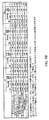
この出願の優先日の時点で商業的に入手可能な幾つかの電池について測定された外部容積および内部容積が、図2Aおよび図2Bに示した表に列挙されている。この表は、Dサイズ、Cサイズ、AAサイズおよびAAAサイズの電池の容積(cc)を列記している.これら商業的に入手可能な電池について、集電体アセンブリーの容積および集電体アセンブリーの容積を構成する全電池容積の割合が、図2Bに与えられている。図2Aには、電気化学的に活性な材料を収容するために利用可能な内部容積を構成する、全電池容積の割合が与えられている。
【0013】
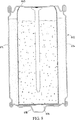
「全電池容積」は、内部空隙を含む電池の全ての容積を含む。図1に示した電池の場合、全量積は、理想的には図3Aに示した斜線領域の全てを含む。電池の「内部容積」は、図3Bに示した斜線領域によって表される。ここで用いる「内部容積」は、電気化学的に活性な材料、並びにシールされた電池容積内に閉じ込められた空隙および化学的に不活性な材料(集電体釘以外)を収容する電池内部の容積である。このような化学的に不活性な材料には、セパレータ、導電体、および電極中の何等かの不活性添加剤が含まれる。ここで説明する「電気化学的に活性な材料」には、正極電極および負極電極、並びに電解質が含まれる。「集電体アセンブリー容積」には、(図3Cに斜線領域で示すように)、集電体釘、シール、不活性カバー、ワッシャー、スパーおよび負極カバー底面とシールとの間の何等かの空隙が含まれる。「容器容積」には、(図3Dに斜線領域で示すように)缶、ラベル、負極カバー、ラベルと負極カバーとの間の空隙、正極カバー、および正極カバーと缶との間の空隙が含まれる。ラベルが負極カバー(外側カバー45)の上に延出し且つこれと接触するときは、ラベルと負極カバーとの間に存在する空隙は容器容積の中に含まれ、従って、全容積の一部とみなされる。そうでなければ、この空隙は容器容積または全容積の何れにも含められない。
【0014】
「内部容積」、「集電体アセンブリー容積」および「容器容積」の総合計は、「全容積」に等しいことが理解されるべきである。従って、電気化学的に活性な材料のために利用可能な内部容積は、集電体アセンブリー容積および容器容積を測定し、測定された電池の全容積から集電体アセンブリー容積および容器容積を差し引くことによって確認することができる。
【0015】
電池の外部寸法は、一般にアメリカ国立標準局(ANSI)または他の標準機関によって固定されるから、集電体アセンブリーによって占められる空間が大きいほど、電気化学的材料のために利用可能な電池内の空間は小さくなる。結局、電池内に与え得る電気化学的材料の量の減少によって、電池のサービス寿命の短縮が生じる。従って、電気化学的活性成分のために利用可能な電池内の内部容積を最大にすることが望ましい。
【0016】
我々は、充分なシール特性を維持し且つ信頼性のある圧力解放機構を可能にしながら、集電体アセンブリーが占める空間および容器容積が占める空間が最小化される電池を構成することによって、これを達成し得ることを見出した。
【0017】
従って、第一の側面において、本発明は、
少なくとも正電極および負電極、並びに電解質を含む電気化学的に活性な材料を収容するための缶であって、開放端および閉鎖端を含む缶と;
前記缶の開放端を横切って配置され且つ前記缶に結合されたカバーであって、これを貫通する孔を有するカバーと;
前記カバーの孔を通って伸び、且つ前記缶の中に伸びて前記正電極および負電極と電気的に接触する電流集電体と;
前記集電体を前記カバーから電気的に絶縁し且つ前記集電体と前記カバーとの間のシールを提供するために、前記集電体と前記カバーの間に配置された第一の絶縁材とを具備した電池を提供する。
【0018】
第二の側面において、本発明は、電池を組立てる方法であって:
閉鎖端および開放端を有する缶の中に電気化学的に活性な材料を充填する工程と; カバーに形成された孔を貫通して電流集電体を配置する工程と;
前記カバーおよび前記集電体の間に絶縁材を与えて、それらの間に電気的絶縁を与える工程と;
前記カバーおよび集電体を、前記缶の開放端に組立てる工程とを具備した方法を提供する。
【0019】
好ましくは、前記缶の表面、より好ましくは前記缶の閉鎖端の表面に圧力解放機構が形成される。加えて、この電池は、好ましくは、前記集電体に電気的に結合された接点端子、および前記カバーを前記接点端子から電気的に絶縁するために、前記接点端子と前記カバーの間に配置された誘電体材料を含む。
【0020】
有利には、前記カバーの孔を通して組立てられた集電体を設けることにより、集電体アセンブリーは顕著に小さい断面形状を有し、これによって電池内ではより小さい空間を占める。更に、この構成は、経時的に従来のアセンブリーよりも小さい水ロスを示し、それによって電池の保存寿命を増大させる電池構成を可能にすることができる。本発明の追加の利点は、利用可能な電池容積の顕著な割合を占有せず、且つ信頼性のある圧力解放機構を提供できることである。更にもう一つの利点は、この電池構造は製造が簡単で且つ必要な材料が少なく、それによって製造コストを低減できることである。更に、電池を充分に密封するために缶に加えるべき半径方向の圧縮力が小さい電池構造を可能にすることによって、より薄い側壁を使用して、より大きな内部電池空間をもたらすことを可能にする。
【0021】
本発明は、図面を参照することによって更に理解されるであろう。
【0022】
上記で説明したように、本発明の主な目的は、電池に設けられる圧力解放機構の信頼性を劣化させることなく、また電池が漏出する可能性を増大させることなく、電気化学的に活性な材料を収容するために電池内で利用可能な内部容積を増大することである。
【0023】
当該電池は、缶の開放端を閉鎖してシールする集電体アセンブリーを含む。この集電体アセンブリーは、電極(例えば負電極)に電気的に接触して配置された釘のような集電体を含む。また、集電体アセンブリーには、好ましくはカバーの中央に形成された孔を有する第一のカバーまたは内側カバーが含まれる。集電体は、該カバーの孔を貫通して配置され、延出する。
【0024】
集電体とカバーの間には誘電性の絶縁材が配置されて、それらの間に誘電性の絶縁を提供する。従って、集電体釘はカバーから電気的に分離される。誘電性絶縁材は、有機ポリマーのような有機巨大分子材料であってもよい。適切な材料には、エポキシ樹脂、ゴムおよびナイロンが含まれる。使用する電解質に対して耐性を有する他の誘電体材料を使用してもよい。アルカリ電池の場合、好ましくは、この誘電体材料は水酸化カリウム(KOH)による攻撃に対して耐性であり、また水酸化カリウムの存在下において非腐食性である。誘電性絶縁材は、以下で更に説明するように、集電体アセンブリーに組立てることができる。
【0025】
圧力解放機構は、好ましくは缶の表面、より好ましくは缶の閉鎖端に形成される。その結果、公知の複雑な集電体/シールアセンブリーは、少ない容積しか消費せず且つ部品の少ない本発明による集電体アセンブリーで置き換えることができる。従って、内部電池容積効率における顕著な改善が得られる。
【0026】
圧力解放機構は、好ましくは、缶の表面に溝を設けることによって形成される。この溝は、例えば缶の底面を鋳造し、底面に溝を切り、または正電極をモールドするときに缶の底面に溝をモールドすることによって形成すればよい。AAサイズの電池の場合、鋳造された溝の底における金属の適切な厚さは、略50μm(2ミル)である。Dサイズの電池の場合、適切な厚さは75μm(3ミル)である。この溝は、略300°の弧状に形成すればよい。溝により形成された形状を僅かに開いた状態に維持することにより、圧力解放機構は効果的なヒンジを有するであろう。
【0027】
圧力解放機構は、電池が破損したときに電気化学的に活性な材料が電池から外部へ直接噴射されるのを防止するように、好ましくは外側カバーの下に配置される。また、電池の正極端子をもう一つの電池の負極端子に押圧させて、電池がもう一つの電池と共に直列に使用されるときには、圧力解放機構を覆う外側カバーを設けることは、陽圧の下で圧力解放機構が外側に湾曲し、最終的に破断することを可能にする。もし、このような状況で外側カバーが存在しなければ、二つの電池間の接触は圧力解放機構が破断するのを妨げるであろう。更に、圧力解放機構を覆う外側カバーが設けられなければ、電池の正極端部の圧力解放機構は更に損傷を受け易いかもしれない。また、外側カバーは周囲環境の腐蝕効果から圧力解放機構を遮蔽し、従って、時期尚早な発散および/または漏れの可能性を低減する。従って、圧力解放機構は、好ましくは電池缶の閉鎖端において、外側カバーの下に形成される。外側カバーは、好ましくは電池の外部正極端子として働く。
【0028】
溝によって画された領域のサイズは、好ましくは、過剰な内部圧により破損したときに、外側カバーによる妨害を受けずに、溝内の領域が外側カバーの正の突出部内においてヒンジで旋回し得るように選択される。一般に、溝によって画定される領域のサイズ、並びに該溝の選択された深さは缶の直径に依存し、また圧力解放機構を破断して内部で発生したガスが逃散するときの圧力に依存する。
【0029】
集電体アセンブリーのカバーは、缶の開放された頂部端に結合され且つシールされる。缶の表面に圧力解放機構を使用することにより、飲料缶型構造を使用して二重シーム閉鎖を形成することが可能になる。この飲料缶型構造は、缶の開放端に挿入すべき如何なる形態のナイロンシールも必要としない点で、他の形態の電池シール構造とは異なる。その代わりに、食品缶詰または飲料缶の頂部を該缶の円筒部分にシールするために通常使用されるシール技術を使用して、カバーは缶の開放端にシールされる。
【0030】
従って、好ましい実施例において、集電体アセンブリーのカバーは、飲料缶型シール技術により二重シーム閉鎖を形成することによって、缶にシールされる。従って、この缶は、その開放端に形成された好ましくは外側に広がったフランジを有する。更に、該カバーは、このフランジの形状に従った、好ましくは僅かに湾曲した周縁エッジを有する。このカバーを缶の開放端を覆って配置したら、シーミングチャックを使用して二重シーム閉鎖を形成すればよい。
【0031】
例えば、一つの実施例ではカバーの上にシーミングチャックが配置され、シーミングチャックの環状の下方延出部が、カバーに形成された環状凹部に収容される。次に、第一のシーミングロールがカバーの周縁に向かって半径方向に移動される。第一のシーミングロールが周縁およびフランジの方に移動するときに、その湾曲表面は周縁部をフランジの回りに折り畳ませる。また、第一のシーミングロールが半径方向内側に移動するときに、該シーミングチャック、缶およびカバーが中心軸の回りに回転されて、周縁部は、缶の全周でフランジの回りに折り畳まれる。更に、第一のシーミングロールが半径方向内側に移動し続けるときに、フランジおよび周縁は下方に折り畳まれる。周縁部およびフランジがこの位置に折り畳まれた後、第一のシーミングロールは缶から遠くへ移動され、次いで、第二のシーミングロールがフランジおよび周縁部に向けて半径方向内側に移動される。この第二のシーミングロールは充分な力を加えて、折り畳まれたフランジおよび周縁部をシーミングチャックに支持された缶の外表面に対して押圧し、固定する。このプロセスの結果として、缶の周縁部はフランジの回りでその下に折り畳まれ、フランジと缶の壁の外表面との間にカシメられる。こうして、このプロセスにより密封シールが形成される。
【0032】
このタイプのシールの密封性を説明するために、図1に示すような従来のシールで構築されたDサイズの缶と共に、本発明のこの実施例に従って構築されたDサイズの缶に水を満たした。この二つの缶を71℃に維持し、経時的に秤量して、缶からの水の喪失を測定した。従来の構造は1週当たり270mgを喪失し、本発明による構造は同じ期間に亘って如何なる重量も喪失しなかった。KOH電解質を用いてこれらの結果を確認したところ、従来の構造では1週当たり50mgを喪失したが、このときも本発明の構造は如何なる重量も喪失しなかった。
【0033】
当業者に明らかなように、飲料缶型構造は電池内部のできるだけ小さい空間を利用して、電池を製造するために必要なプロセス工程の数を減少し、材料コストおよび製造プロセスのコストを顕著に低減する。更に、缶壁の厚さは、例えば150μm(6ミル)未満にまで顕著に低下される。その結果、電気化学的に活性な材料を収容するために利用可能な内部容積を増大させることができる。例えば、本発明によるDサイズの電池の場合、電気化学的に活性な材料を収容するために使用し得る全電池容積の割合は、96容量パーセントと高くできる一方、集電体アセンブリー容積は2.6容量パーセントと低くできる。他のサイズの電池の容積は、図9Aおよび図9Bに示す表に含まれている。
【0034】
飲料缶型構造を利用することによって、缶壁の厚さを減少できるだけでなく、缶が示さなければならない強度要件が低くなることによって、缶を形成するために使用可能な材料の数もまた増大する。例えば、上記の飲料缶構造は、缶のために現在使用されているニッケルメッキ鋼以外に、アルミニウムまたはプラスチックを使用することを可能にする。
【0035】
飲料缶型構造の変形例において、先ず、電池は二つの開放端をもった管として形成される。この管は、例えば従来の技術を使用して押出され、シーム溶接され、半田付けまたはカシメられる。この缶は、例えば鋼、アルミニウムまたはプラスチックで形成すればよい。缶は、缶の側壁を定義する。缶の第一の開放端は、上記で概説した飲料缶シのール技術を用いることによってシールされる。正極接点端子は、カバーの外表面に溶接または固定すればよい。次いで、電池を充填し、上述したのと同じ方法で、缶の第二の開放端に集電体アセンブリーのカバーを固定すればよい。或いは、缶が充填されて他のカバーにシールされる前に、集電体アセンブリーのカバーを缶にシールしてもよい。
【0036】
二重シームの缶/カバー閉鎖が好ましいが、本発明に従って他の缶/カバー閉鎖を用いてもよいことが理解されるべきである。
【0037】
本発明による電池は、缶およびカバーの間の直接結合を可能にし、これは、好ましくはそれらの間の圧力シールを提供するが、カバーと缶側壁との間の電気的絶縁を必要としない。その代わり、電池の負極および正極端子が相互に電気的に分離されるように、集電体、好ましくは釘がカバーから誘電的に絶縁される。缶とカバーの間の電気的分離を維持する必要は存在しないが、缶に対するカバーのシールを補助するために、缶をカバーに結合する閉鎖部に密閉材(sealant)を塗布するのが好ましい。カバー周縁部の底面に従来の密閉材を適用すればよい。飲料缶構造では、シール手順が完了したら密閉材は図7Dに示す位置へと移動する。絶縁材と共にシールされた閉鎖部は、圧力解放機構が圧力を放出する換気圧力よりも大きい内部発生圧力に耐え得べきことが理解されるべきである。
【0038】
広く受け容れられている電池標準に従って許容可能な外部電池端子を提供するために、電池は更に、集電体と電気的に接触した外側カバーを含んでいる。この外側カバーは点溶接によって溶接され、または集電体に電気的に結合すればよい。外側カバーと内側カバーとの間の適切な電気的絶縁を保証するために、好ましくは、環状パッドのような誘電体材料が、外側カバーと内側カバーとの間に配置される。適切な誘電体材料には、ナイロン、他のエラストマー材料、ゴム、およびエポキシ樹脂が含まれ、これらは内側カバーの頂部表面または外側カバーの低部表面に適用される。従って、許容可能な標準電池端子は、好ましくは、負端末として電池の集電体端に設けられる。
【0039】
本発明の好ましい実施例に従う電池の組立てが図11の組立て図に示されており、また図12のフロー図に更に示されている。組立ての好ましい方法には、底部端が閉じられ頂部端が開放された缶を準備することと、該缶の中に、負電極、正電極および電解質を含む電気化学的に活性な材料、並びにセパレータおよび他の電池添加剤を充填することが含まれる。活性な電池材料が缶の中に配置されたら、この缶は、集電体アセンブリーを用いて閉鎖およびシールするための準備が完了する。
【0040】
缶を閉じる前に、先ず、集電体が絶縁リングの開口部に配置されるように、好ましくは絶縁材のリングまたはディスクと共に、カバーに形成された孔の中に集電体(好ましくは釘)を配置することによって、集電体アセンブリーが組立てられる。絶縁リングは、好ましくは、誘電性絶縁を提供し、且つ加熱により変形させてカバーと集電体の間に設置できる材料、例えばエポキシ樹脂で形成される。或いは、エポキシ樹脂の代わりに、ゴム製グロメット、エラストマー材料のような他の有機巨大分子(高分子)の誘電性絶縁材料、または集電体とカバーの間に充分な絶縁を形成し得る誘電体材料を使用してもよい。
【0041】
好ましくは、カバーの頂部表面には、前記孔の回りに位置合わせされた凹部が形成される。従って、カバー頂部の該凹部内に絶縁材のリングを配置すればよく、また集電体釘の頂部ヘッドをその上に配置すればよい。こうして、絶縁リングは集電体釘およびカバーに組立てられ、また、この絶縁リングは、溶融するために充分に高い温度に加熱され、変形してカバーの穴の中に流れ込み、集電体釘とカバーの間に連続的な誘電性絶縁を提供する。エポキシ製リングの場合、絶縁材を変形および硬化させるためには、20℃〜200℃の温度で数秒〜24時間の加熱で充分である。誘電体材料が集電体釘とカバーの間の充分な絶縁を形成したら、好ましくは該絶縁材を冷却する。この加熱工程および冷却工程の際、集電体釘はカバーに接触しないように前記孔の中に心合わせされる。
【0042】
その後、好ましくは、環状誘電体パッドのような誘電性電気絶縁パッドが、釘の周囲から外側に向けて半径方向に伸びるように、カバーの頂部に配置される。次いで、導電性の負極カバーが集電体釘およびパッドの頂部に配置されて溶接され、または集電体釘との電気的接触が形成される。
【0043】
集電体アセンブリーが完全に組立てられたら、次いで、集電体アセンブリーを缶に結合して開放端を密封閉鎖する。他の適切な缶閉鎖技術を使用してもよいが、好ましくは、缶の閉鎖には二重シーム閉鎖を用いる。加えて、好ましくは缶の閉鎖端に、好ましくは圧力解放機構を覆って第二のカバーが結合される。
【0044】
好ましい実施例では、
開放端および閉鎖端を有する缶を形成する工程と;
孔を有するカバーを形成する工程と;
前記缶の中に電気化学的に活性な材料を配置する工程と;
前記カバーの孔を通って伸びる電流集電体を組立てる工程と;
前記集電体と前記カバーの間に連続的に絶縁材を配置する工程と;
前記カバーを前記缶の開放端に配置して、前記缶の開放端を覆い且つシールする工程とを含む方法が提供される。
【0045】
更なる実施例において、前記缶は、その閉鎖端に直接形成された正極電池端子のための突出部を有するように形成してもよい。この方法では、缶の閉鎖端と正極外側カバーの間に伸びる空隙を使用して、電気化学的に活性な材料を収容し、或いはガスを集めるための空間を提供することができるが、このようにしないのであれば、このような空間電池内に用意しなければならない。この突出部を缶の底に直接形成することによって得られる電池容積の増大は、図9Aの表には与えられていないが、当業者は、表に列記したフィードスルー集電体電池を備えた飲料缶について記載した容積よりも、その内部容積が典型的には1%大きいことを理解するであろう。
【0046】
更なる実施例では、塗料層を電池の缶の外表面に直接塗布してラベルが与えられる。ラベル基材を用いずに、缶の外側にラベルを直接塗布することによって、電池の内部容積を更に増大することができる。何故なら、ANSIまたは他の外部表面標準に適合した電池を構築するために、ラベル基材の厚さを考慮しなくて済むからである。「直接」の語は、印刷層と電池缶の外表面との間にラベル基材が存在しないことを意味する。現行のラベル基材は略75μm(3ミル)の厚さを有する。このようなラベル基材は重なってシームを形成するから、これら従来のラベルは、電池の直径に約250μm(10ミル)を加え、また電池のカシメ高さに330μm(13ミル)を加える。その結果、ANSIまたは他のサイズ標準に適合するために、電池はラベルシームの厚さに適合するように選択された直径を有していなければならない。しかし、リソグラフ加工されたラベルを缶の外表面に直接印刷することによって、缶の直径はこれに対応して略250μm(10ミル)増大し得る。このような缶の直径の増大は、電池の内部容積を顕著に増大させる。従って、基材ラベルを備えた電池の内部容積は、該ラベルを缶の外部に直接印刷すれば、例えばDサイズの電池については2パーセント(1.02 cc)、Cサイズの電池については2.6パーセント(0.65 cc)、AAサイズの電池については3.9%(0.202 cc)、AAAサイズの電池については5.5パーセント(0.195 cc)だけ更に増大することができるであろう。
【0047】
また、ラベルは転写印刷技術を用いて缶に印刷してもよく、この場合、ラベル画像は先ず転写媒体上に印刷され、次いで缶の外表面に直接転写される。歪みリソグラフィーを使用してもよく、この場合は、その後に管または缶の円筒に成形するときの平坦材料の応力歪みを考慮して、意図的に歪んだ画像を平坦な材料上に印刷する。
【0048】
リソグラフ加工されたラベルを印刷する前に、好ましくは、缶の外表面を清浄化する。缶への印刷の接着を高めるために、缶の外表面にプライマーのベースコートを塗布してもよい。次いで、公知のリソグラフィー印刷技術によって、缶のベースコート頂部に印刷層を直接塗布する。ラベルは、更に電気絶縁性のオーバーコートを含んでいてもよい。好ましくは、印刷層を覆って保護し、また電気絶縁層として機能させるために、ワニスオーバーコートが印刷層を覆って塗布される。印刷されたラベルは、高温加熱または紫外線照射技術を使用して硬化させればよい。
【0049】
印刷ラベルを使用すると、基材上の従来のラベルと比較して、ラベルの厚さは略13μm(0.5ミル)の最大厚さに顕著に減少する。特定の実施例において、印刷ラベルは約0.25〜5μm(0.1〜0.2ミル)の厚さのベースコート層、略2.5μm(0.1ミル)の厚さの印刷層、および約2.5〜5μm(0.1〜0.2ミル)の厚さのワニスオーバーコート層を有している。
【0050】
ラベル厚さを低減することによって缶は直径を増大させることができ、これによって、電池の所定の外径を維持しながら、活性な電池材料のために利用可能な容積の更なる増大を提供することができる。
【0051】
理解されるように、上述の構造を使用することによって、電池はより薄い壁(略100〜200μm;4〜8ミル)を用いて製造することができる。何故なら、以下で概説する構築技術は、充分なカシメおよびシールを保証するために、従来の電池に必要とされる厚い壁を必要としないからである。更に、ラベルを電池缶の外表面に直接リソグラフ加工してもよい。缶の壁を薄くし且つ缶の外表面にラベルを直接リソグラフ加工することによって、ANSI外径サイズ標準に適合する電池を構築するためにラベル基材の厚さを考慮しなくて済むので、電池の内部容積は更に増大する。
【0052】
主にアルカリ電池に対する適用を有するものとして本発明を説明してきたが、当業者は、本発明の構成を他の電気化学システムを利用する電池に適用しても同様の利益が得られることを理解するであろう。例えば、本発明の構成は、炭素/亜鉛およびリチウム系電池のような一次システム、並びにNiCd、水素化金属およびLi系電池のような再充電可能な電池にも採用できる。更に、本発明の一定の構造は、生電池(即ち、バッテリーパックまたは多重電池バッテリーに使用するラベルのない電池)に使用してもよい。加えて、円柱形の電池に関連して本発明を説明してきたが、本発明の一定の構造は角柱形の電池に使用してもよい。
【0053】
次に、図4〜図12に示した実施例を参照して本発明を更に説明する。
【0054】
図10を参照すると、本発明の一実施例に従って、フィードスルー集電体を用いて構成された電池700が示されている。図6に示した飲料缶型構造を用いた電池400と同様に、電池700は導電性の缶712を含んでおり、該缶は閉鎖端314を有し、また低容積の集電体アセンブリー725および外側負極カバー750が組立てられる開放端を有する。正極(カソード)115は、缶712の内部壁に接触し、また正極115と負極(アノード)との間に配置されるセパレータ117と接触する。圧力解放機構370が、缶712の閉鎖端314に形成される。図4および図5と関連して説明したように、圧力解放機構370は溝372として形成される。加えて、正極外側カバー311は缶712の閉鎖端に結合され、圧力解放機構370の上に置かれる。集電体アセンブリー725は缶712の開放端を閉じ、且つシールする。集電体アセンブリー725は、負極120に電気的に接触して配置された集電体釘740を含んでいる。また、集電体アセンブリー725には、その中に形成された中心孔751を有する第一のカバーまたは内側カバー745が含まれている。集電体釘740は、内側カバー745の孔751を貫通して配置され、延出する。集電体釘740と第一のカバー745との間には誘電性絶縁材744が配置され、それらの間に誘電性の絶縁を提供する。内側カバー745は、周縁部450および470の二重シーム閉鎖によって、缶712の開放端に結合およびシールされる。外側カバー750は、集電体釘740に電気的に接触している。外側負極カバー750と内側カバー745との間には、誘電体環状パッド748が配置される。従って、カバー750によって負の電池端子が提供される。
【0055】
以下に、図7A〜7Dを参照して説明するように、本発明の好ましい実施例に従う電池は、飲料缶型シールを有するように製造される。カバー745(図7A〜7Dのカバー445に対応する)は、図7Bに示すように、缶712の開放端を覆って配置される。缶712は、その開放端に形成された、外側に向かって広がるフランジ450を有している。更に、カバー745は、フランジ450の形状に適合した僅かに湾曲した周縁部を有している。カバー745が缶712の開放端を覆って配置されたら、シーミングチャック500の下方に伸びる環状部分502がカバー745に形成された環状凹部472に収容されるように、シーミングチャック500がカバー745上に配置される。次に、第一のシーミングロール510が、カバー周縁部470に向けて半径方向に移動される。第一のシーミングロール510が周縁部470およびフランジ450に向けて移動すると、その湾曲した表面は、周縁部470をフランジ450の回りに折り畳ませる。また、第一のシーミングロール510が半径方向内側に移動するときに、シーミングチャック500、缶712およびカバー745が中心軸の回りに回転する結果、周縁部470は缶712の全周でフランジ450の回りに折り畳まれる。更に、第一のシーミングロール510が半径方向内側に移動し続けるときに、フランジ450および周縁部470は、図7Cに示す位置にまで下方に折り畳まれる。周縁部470およびフランジ450が図7Cに示す位置まで下方に折り畳まれた後に、第一のシーミングロール510は缶712から遠くへ移動され、次いで第二のシーミングロール520がフランジ450および周縁部470に向けて半径方向内側へと移動される。第二のシーミングロール520は、第一のシーミングロール510とは異なる断面形状を有している。第二のシーミングロール520はフランジ450および周縁部470に対して充分な力を加え、折り畳まれたフランジおよび周縁部を、シーミングチャック500に支持された缶712の外表面に押圧して平坦化する。このプロセスの結果として、缶712の周縁部470は、フランジ450の周囲で且つその下に折り畳まれ、図7Dおよび図10に示すように、フランジ450と缶712の壁の外表面との間でカシメられる。外側カバー745の缶712へのシールを補助するために、従来の密閉材473を、カバー745の周縁部470の底面に塗布してもよい。このシール手順が終了したら、密閉材473は図7Dに示す位置へと移動する。こうして、この方法により密封シールが形成される。
【0056】
図8は、飲料缶構造の変形例を示しており、この場合、飲料缶は先ず二つの開放端をもった管として形成される。この管は、缶61の側壁614を定義する。次いで、上記で概説した飲料缶シール技術を使用して内側カバー616を固定することにより、内側カバー616と側壁614との間の電気絶縁を伴わずに、第一の開放端がシールされる。正極外側カバー618を、内側カバー616の外表面に溶接または固定すればよい。次いで電池が充填され、上記で述べたのと同じ方法で、集電体アセンブリー725(図示せず)を缶の第二の開放端に固定すればよい。
【0057】
本発明の一実施例による電池700の組立てが、図11の組立て図に例示されており、更に、図12のフロー図に示されている。電池700の組立て方法は、工程772において、底端部を閉鎖し頂部端を開放して形成された管712を準備することを含む。工程774は、負電極、正電極および電解質を含む電気化学的に活性な材料、並びにセパレータおよび他の電池添加剤を缶712の中に配置することを含む。活性な電池材料が缶712の中に配置されたら、缶712は、集電体アセンブリー725を用いて閉鎖およびシールするための準備が完了する。缶を閉鎖する前に、先ず、工程776に従って、集電体釘740を絶縁材のリングと共に、内側カバー745の中に形成された孔751内に配置することによって集電体アセンブリーが組立てられる。集電体釘740は絶縁リング744の開口部の中に配置されるが、該リングは誘電性の絶縁を提供し、また、加熱されて内側カバー745と集電体釘740との間に設置されるように変形することができる。頂部表面には凹部755が形成され、これは孔751の回りにセンタリングされる。絶縁材のリング744は、内側カバー745の頂部における凹部755内に配置され、集電体釘740の頂部ヘッドがその上に配置される。工程778において、絶縁リング744は集電体釘740およびカバー745と一緒に組立てられ、また、絶縁リング744は該リングが溶融するのに充分に高い温度に加熱されて、変形してカバー745の孔の中に流れ込み、集電体釘740とカバー745との間に誘電性の連続的な絶縁を与える。エポキシ製リング744の場合、この絶縁材を変形および硬化させるためには、20℃〜200度の温度で数秒〜24時間で充分である。誘電体材料744が集電体釘740と内側カバー745との間に充分な絶縁を形成したら、工程780において、該絶縁材を冷却させるのが好ましい。加熱および冷却工程778および789の際、集電体釘740はカバー745に接触しないように、孔751にセンタリングされる。その後、工程782において、釘740の周囲から外側に向かって半径方向に広がる環状誘電体パッドのような、誘電性の電気絶縁パッド748が内側カバー745の頂部に配置される。工程784において、釘740およびパッド748の頂部には導電性の負極カバー750が配置され、これは集電体釘740との間で溶接され、または電気的接続が形成される。集電体アセンブリーが完全に組立てられたら、工程786に与えられているように、該集電体アセンブリーを缶に結合して開放端を密封閉鎖する。缶の閉鎖には、二重シーム閉鎖または他の適切な缶閉鎖技術を用いればよい。加えて、この組立て方法770は、第二の外側カバーを、好ましくは圧力解放機構370の上に配置して缶の閉鎖端に結合する工程788を含む。
【0058】
図面に示し且つ上記で説明した実施例は例示目的のために過ぎず、本発明の範囲を制限するものでないことが理解されるであろう。
【0059】
例
夫々の電池について、コンピュータ支援設計(CAD)図面、写真、またはエポキシ樹脂に収容された電池の実際の横断面、および長手方向断面を観察することによって、全電池容積、集電体アセンブリー容積、および電気化学的に活性な材料のために利用可能な内部容積を測定した。CAD図面、写真、または実際の長手方向断面を使用して電池の寸法を観察および測定することにより、電池の中に存在し得る全ての空隙容積を含めることが可能になる。全電容積を決定するためには、電池の長手方向の中心対称軸に沿った断面図を観察し、幾何学的コンピュータ処理によって全容積を測定する。電気化学的に活性な材料のために利用可能な内部容積を決定するためには、その長手方向の中心対称軸に沿った電池の断面図を観察し、電気化学的に活性な材料、空隙容量および化学的不活性材料(集電体釘以外)を含む、電池のシールされた容積内に閉じ込められた内部容積を構成する全ての成分を幾何学的コンピュータ処理によって測定する。同様に、集電体アセンブリーの容積を決定するためには、その長手方向の中心対称軸に沿った電池の断面図を観察し、集電体釘、シール、内側カバー、および負極カバーの底面とシールとの間の形成される空隙容積を含む、集電体アセンブリー容積を構成する成分を幾何学的コンピュータ処理によって測定する。容器容積も同様に、電池の中心長手方向断面を観察し、缶、ラベル、負極カバー、ラベルと負極カバーとの間の空隙容積、正極カバー、および正極カバーと缶との間の空隙容積で占められる容積をコンピュータ計算することによって測定される。
【0060】
容積測定は、その長手方向の対称軸に沿った電池の断面を観察することによって行われる。通常、電池およびその部品は軸対称であるから、これによって正確な容積測定が提供される。電池断面の幾何学図を得るためには、電池を先ずエポキシ樹脂の中にポッティングし、エポキシ樹脂が固化した後に、ポッティングされた電池およびその部品を、対称軸を通る中心断面まで摩滅させる。より具体的に言えば、先ず、電池をエポキシ樹脂の中にポッティングし、次いで中心断面のショートを摩滅させる。次に、完成された断面のより良好な測定を可能にするために、アノード、カソードおよびセパレータ紙のような全ての内部部品を除去する。次いで、ポッティングされた電池から如何なる残留破片をも除去し、空気乾燥し、残留空隙容積にエポキシ樹脂を充填して、その中心への摩滅および研磨を完了する前に電池に幾らかの一体性を与える。再度、電池をその中心断面が完成するまで摩滅および研磨し、その後に図面にトレースし、これから容積を測定する。
【0061】
電池をエポキシ樹脂の中にポッティングする前に、キャリパーを用いて電池測定を行い、電池の全体の高さ、カシメ高さ、並びに頂部、底部および中心の外径を測定した。加えて、同一の電池を分解し、その部品を測定した。分解された電池のこれら部品の測定には、現行の集電体釘の直径、現行の集電体釘の長さ、負極カバーまでの現行の集電体釘の長さ、並びにラベルの存在しない電池の頂部、底部および中心における外径が含まれる。
【0062】
電池がエポキシ樹脂の中に完全にポッティングされたら、電池の断面図を使用して図面を作成する。QC-400ソフトウエアを備えたミツトヨ(Mitutoyo)光学コンパレータを使用して、電池およびその部品の輪郭をトレースし、電池の中心断面の図を作製する。これを行う際には電池を正しい場所にしっかり固定し、電池部品の輪郭は、問題の電池容積を計算するために、後で固体モールドソフトウエアで使用できるフォーマットの中に保存した。しかし、容積測定を行う前に、電池の中心を通って正確に整列されていない電池部品について補償するために、図面を調節してもよい。これは、電池を切断する前の電池から行われた測定、および分解された同一の電池から行われた測定を使用することによって達成することができる。例えば、容積測定について図面をより正確にするために、対応する既知の断面寸法を含むように図面を調節することによって、現行の集電体釘の直径および長さ並びに電池全体の外径は、図面をより正確に描くように修正することができる。シール、カバーおよびカシメ領域の詳細は、それらが光学コンパレータ上に描かれた通りに使用された。
【0063】
容積測定を計算するために、図面を固体モールドソフトウエアの中に移入した。固体の三次元容積表現は、断面の輪郭を左右の両側で長手対称軸の回りに180°回転させることによって作成された。従って、問題の各領域の容積は、ソフトウエアによって右側および左側を180°回転させ、右側容積および左側容積を合計し、平均容積を決定することによって計算される。これは、電池が非対称構造を有する場合に有利である。何等かの非対称構造を含む容積は、必要に応じて、より正確な容積測定を得るように調節することができる。
【0064】
図9Aおよび図9Bは、1998年10月2日に出願されたUS 60/102,951号および1998年8月21日に出願されたUS 60/090,445号に更に完全に開示された、種々の異なるタイプの電池構造の容積を示している。図9Aの「フィードスルー集電体を備えた飲料缶」の列に示すように、図10に示した構造を使用して構成されたDサイズの電池は、缶壁の厚さが200μm(8ミル)であるときの96.0容量パーセントの内部容積を有していた。図9Bに示すように、図10に示した構造を用いて構成されたDサイズの電池は、缶壁の厚さが200μm(8ミル)であるときの全容積の2.6パーセントの集電体アセンブリー容積を有していた。同様の構造を有するCサイズ、AAサイズおよびAAAサイズの電池もまた、図9Aの表から明らかなように、内部容積効率における顕著な改善を示した。
【図面の簡単な説明】
【図1】 図1は、Cサイズの従来のアルカリ電池を示す断面図である。
【図2】 図2Aは、この出願の優先日時点において商業的に入手可能であった電池について測定された、全電池容積および電気化学的に活性な材料のために利用可能な内部電池容積を比較して示す表である。
【図3】 図2Bは、図2Aの商業的に入手可能な電池について測定された、全電池容積および集電体アセンブリー容積を比較して示す表である。
【図4】 図3Aは従来のCサイズのアルカリ電池の断面図であり、全電池容積および種々の部品容積を示している。
【図5】 図3Bは従来のCサイズのアルカリ電池の断面図であり、全電池容積および種々の部品容積を示している。
【図6】 図3Cは従来のCサイズのアルカリ電池の断面図であり、全電池容積および種々の部品容積を示している。
【図7】 図3Dは従来のCサイズのアルカリ電池の断面図であり、全電池容積および種々の部品容積を示している。
【図8】 図4は、缶の閉鎖端に形成された圧力解放機構を有する電池缶の底面図である。
【図9】 図5は、図4に示した缶通気孔のX−X線に沿った断面図である。
【図10】 図6は、飲料水缶型構造を有するCサイズのアルカリ電池の断面図である。
【図11】 図7Aは、図6に示した電池の一部分解斜視図である。
【図12】 図7Bは、図6に示した電池の一部を示す断面図であり、飲料水缶型構造を形成するための方法を示している。
【図13】 図7Cは、図6に示した電池の一部を示す断面図であり、飲料水缶型構造を形成するための方法を示している。
【図14】 図7Dは、図6に示した電池の一部を示す拡大断面図である。
【図15】 図8は、飲料缶型構造を有するCサイズのアルカリ電池の断面図である。
【図16】 図9Aは、種々の電池について計算された全電池容積および内部電池容積を示す表である。
【図17】 図9Bは、種々の電池について計算された全電池容積および集電体アセンブリー容積を示す表である。
【図18】 図10は、本発明の実施例による集電体フィードスルー構造を有する、Cサイズのアルカリ電池を示す断面図である。
【図19】 図11は、図10に示した電池の分解組立て図である。
【図20】 図12は、図10および図11に示した電池の組立て方法を示すフロー図である。[0001]
The present invention generally includes battery Concerning the configuration of More particularly, the present invention is similar to alkaline batteries. battery Container used for and Current collector Regarding the assembly.
[0002]
FIG. 1 shows the structure of a conventional C-size
[0003]
The
[0004]
When the
[0005]
Once the
[0006]
As shown in FIG. Current collector Nbury has 30 seals, Current collector A
[0007]
Further, the
[0008]
Current collector In order to improve the sealing effect by increasing the stiffness of the assembly and supporting its radial compression, an
[0009]
The
[0010]
The
[0011]
the above Current collector The
[0012]
The external and internal volumes measured for several commercially available batteries as of the priority date of this application are listed in the tables shown in FIGS. 2A and 2B. This table lists the battery capacity (cc) of D size, C size, AA size and AAA size batteries. For these commercially available batteries, Current collector Volume and Current collector Of the total battery volume constituting the volume of the battery Percentage Is given in FIG. 2B. In FIG. 2A, Electrochemically active material Make up the internal volume available to accommodate the total battery volume Percentage Is given.
[0013]
“Total battery volume” includes the entire volume of the battery including internal voids. In the case of the battery shown in FIG. 1, the total volume product ideally includes all of the shaded area shown in FIG. 3A. The “internal volume” of the battery is represented by the hatched area shown in FIG. 3B. The "internal volume" used here is Electrochemically active material As well as voids and chemically inert materials confined within the sealed battery volume ( Current collector It is the volume inside the battery that accommodates (other than nails). Such chemically inert materials include separators, conductors, and any inert additives in the electrodes. The “electrochemically active material” described here includes a positive electrode, a negative electrode, and an electrolyte. " Current collector ‘Nubry volume’ (as shown by the shaded area in FIG. 3C), Current collector Included are nails, seals, inert covers, washers, spars and any gaps between the bottom of the negative cover and the seal. “Container volume” includes can, label, negative electrode cover, gap between label and negative electrode cover, positive electrode cover, and gap between positive electrode cover and can (as shown by the shaded area in FIG. 3D) It is. When the label extends over and contacts the negative electrode cover (outer cover 45), the air gap that exists between the label and the negative electrode cover is included in the container volume, and thus a portion of the total volume. It is regarded. Otherwise, this void is not included in either the container volume or the total volume.
[0014]
"Internal volume", " Current collector It should be understood that the total sum of “bulb volume” and “vessel volume” is equal to “total volume”. Thus, the available internal volume for an electrochemically active material is Current collector Battery volume and container volume, and from the measured total battery volume Current collector This can be confirmed by subtracting the volume and container volume.
[0015]
battery The external dimensions of are generally fixed by the American National Standards Institute (ANSI) or other standards bodies, Current collector The larger the space occupied by the battery, the less space in the battery available for electrochemical materials. Ultimately, a reduction in the amount of electrochemical material that can be provided in the battery results in a reduction in the service life of the battery. Thus available for electrochemically active ingredients battery It is desirable to maximize the internal volume inside.
[0016]
While maintaining sufficient sealing properties and enabling a reliable pressure relief mechanism, Current collector The space occupied by the container and the container volume is minimized battery It has been found that this can be achieved by configuring
[0017]
Accordingly, in the first aspect, the present invention provides:
Including at least positive and negative electrodes and electrolyte Electrochemically active material A can for containing a can comprising an open end and a closed end;
A cover disposed across the open end of the can and coupled to the can, the cover having a hole therethrough;
An electric current extending through the hole in the cover and extending into the can into electrical contact with the positive and negative electrodes Current collector When;
Above Current collector Electrically insulated from the cover and the Current collector To provide a seal between the cover and the cover Current collector And a first insulating material disposed between the covers. battery I will provide a.
[0018]
In a second aspect, the present invention provides: battery How to assemble:
In a can with a closed end and an open end Electrochemically active material Filling a current through the hole formed in the cover; Current collector Placing the step;
The cover and the Current collector Providing an insulating material between and providing electrical insulation between them;
Said cover and Current collector Assembling to the open end of the can.
[0019]
Preferably, a pressure release mechanism is formed on the surface of the can, more preferably on the surface of the closed end of the can. Plus this battery Is preferably Current collector A contact terminal electrically coupled to the contact terminal, and a dielectric material disposed between the contact terminal and the cover for electrically insulating the cover from the contact terminal.
[0020]
Advantageously assembled through a hole in the cover Current collector By providing Current collector Is quite small Cross-sectional shape And thereby battery Occupies a smaller space within. In addition, this configuration can allow battery configurations that exhibit less water loss over time than conventional assemblies, thereby increasing battery shelf life. An additional advantage of the present invention is a significant increase in available battery volume. Percentage And a reliable pressure release mechanism can be provided. Yet another advantage is that this battery structure is simple to manufacture and requires less material, thereby reducing manufacturing costs. In addition, by allowing a battery structure with less radial compression force to be applied to the can to sufficiently seal the battery, it is possible to use thinner sidewalls to provide more internal battery space. .
[0021]
The invention will be further understood by reference to the drawings.
[0022]
As explained above, the main object of the present invention is to reduce the reliability of the pressure release mechanism provided in the battery and without increasing the possibility of the battery leaking. Electrochemically active material To increase the internal volume available in the battery to accommodate.
[0023]
Concerned battery Close and seal the open end of the can Current collector Including. this Current collector Like a nail that is placed in electrical contact with an electrode (eg, a negative electrode) Current collector including. Also, Current collector The assembly preferably includes a first cover or inner cover having a hole formed in the center of the cover. Current collector Is disposed through the hole of the cover and extends.
[0024]
Current collector A dielectric insulation is disposed between the cover and the cover to provide dielectric insulation therebetween. Therefore, Current collector The nail is electrically separated from the cover. The dielectric insulating material may be an organic macromolecular material such as an organic polymer. Suitable materials include epoxy resin, rubber and nylon. Other dielectric materials that are resistant to the electrolyte used may be used. In the case of alkaline cells, preferably the dielectric material is resistant to attack by potassium hydroxide (KOH) and is non-corrosive in the presence of potassium hydroxide. The dielectric insulation is, as will be further described below, Current collector Can be assembled into
[0025]
The pressure release mechanism is preferably formed on the surface of the can, more preferably on the closed end of the can. As a result, known complex Current collector The seal assembly consumes less volume and has fewer parts according to the invention Current collector Can be replaced. Thus, a significant improvement in internal battery volume efficiency is obtained.
[0026]
The pressure release mechanism is preferably formed by providing a groove on the surface of the can. This groove may be formed, for example, by casting the bottom surface of the can, cutting the groove on the bottom surface, or molding the groove on the bottom surface of the can when the positive electrode is molded. For AA size batteries, a suitable metal thickness at the bottom of the cast groove is approximately 50 μm (2 mils). For D size batteries, a suitable thickness is 75 μm (3 mils). This groove may be formed in an arc shape of approximately 300 °. By keeping the shape formed by the grooves slightly open, the pressure release mechanism will have an effective hinge.
[0027]
When the battery is damaged, the pressure release mechanism Electrochemically active material Is preferably placed under the outer cover so as to prevent spraying directly from the battery to the outside. Also, when the battery positive electrode terminal is pressed against the other battery negative electrode and the battery is used in series with another battery, it is necessary to provide an outer cover that covers the pressure release mechanism under positive pressure. The pressure release mechanism curves outwards and allows it to eventually break. If there is no outer cover in this situation, contact between the two cells will prevent the pressure release mechanism from breaking. Furthermore, if an outer cover is not provided to cover the pressure release mechanism, the pressure release mechanism at the positive end of the battery may be more susceptible to damage. The outer cover also shields the pressure release mechanism from the corrosive effects of the surrounding environment, and thus Premature divergence And / or reduce the possibility of leakage. Thus, the pressure release mechanism is formed below the outer cover, preferably at the closed end of the battery can. The outer cover preferably serves as the external positive terminal of the battery.
[0028]
The size of the area defined by the groove is preferably such that the area in the groove can be hinged in the positive projection of the outer cover without being disturbed by the outer cover when broken by excessive internal pressure. Selected as In general, the size of the area defined by the groove, as well as the selected depth of the groove, depends on the diameter of the can, and also on the pressure at which the internally generated gas escapes by breaking the pressure release mechanism. .
[0029]
Current collector The envelope cover is coupled and sealed to the open top end of the can. By using a pressure release mechanism on the surface of the can, it is possible to create a double seam closure using a beverage can-type structure. This beverage can-type structure differs from other forms of battery seal structures in that it does not require any form of nylon seal to be inserted into the open end of the can. Instead, the cover is sealed to the open end of the can using a sealing technique commonly used to seal the top of a food can or beverage can to the cylindrical portion of the can.
[0030]
Thus, in a preferred embodiment, Current collector The cover of the bottle is sealed to the can by forming a double seam closure with beverage can-type sealing technology. The can therefore has a flange formed at its open end, preferably extending outward. Furthermore, the cover has a peripheral edge, preferably slightly curved, according to the shape of this flange. Once this cover is placed over the open end of the can, a seam chuck may be used to form a double seam closure.
[0031]
For example, in one embodiment, a seaming chuck is disposed on the cover, and an annular downward extending portion of the seaming chuck is accommodated in an annular recess formed in the cover. Next, the first seaming roll is moved in the radial direction toward the periphery of the cover. As the first seaming roll moves toward the periphery and flange, the curved surface causes the periphery to fold around the flange. Further, when the first seaming roll moves radially inward, the seaming chuck, can and cover are rotated around the central axis, and the peripheral portion is folded around the flange all around the can. It is. Furthermore, as the first seaming roll continues to move radially inward, the flange and periphery are folded downward. After the rim and flange are folded into this position, the first seaming roll is moved away from the can and then the second seaming roll is moved radially inward toward the flange and rim. . This second seaming roll applies a sufficient force to press and fix the folded flange and peripheral edge against the outer surface of the can supported by the seaming chuck. As a result of this process, the peripheral edge of the can is folded around and under the flange and crimped between the flange and the outer surface of the can wall. Thus, a hermetic seal is formed by this process.
[0032]
To illustrate the sealability of this type of seal, a D-size can constructed according to this embodiment of the present invention is filled with water, along with a D-size can constructed with a conventional seal as shown in FIG. It was. The two cans were maintained at 71 ° C. and weighed over time to determine water loss from the cans. The conventional structure lost 270 mg per week and the structure according to the invention did not lose any weight over the same period. When these results were confirmed using a KOH electrolyte, 50 mg per week was lost in the conventional structure, and at this time, the structure of the present invention did not lose any weight.
[0033]
As can be appreciated by those skilled in the art, the beverage can structure Space as small as possible Is used to reduce the number of process steps required to manufacture a battery, significantly reducing material costs and manufacturing process costs. Furthermore, the can wall thickness is significantly reduced, for example, to less than 150 μm (6 mils). as a result, Electrochemically active material The internal volume available for housing the can be increased. For example, in the case of a D size battery according to the present invention, Electrochemically active material Of the total battery volume that can be used to accommodate Percentage Can be as high as 96 volume percent, Current collector The assembly volume can be as low as 2.6 volume percent. Other battery sizes are included in the tables shown in FIGS. 9A and 9B.
[0034]
By utilizing a beverage can mold structure, not only can the thickness of the can wall be reduced, but the number of materials that can be used to form the can is also increased by reducing the strength requirements that the can must exhibit. To do. For example, the beverage can structure described above allows the use of aluminum or plastic in addition to the nickel-plated steel currently used for cans.
[0035]
In a variant of the beverage can type structure, the battery is first formed as a tube with two open ends. The tube is extruded, seam welded, soldered or crimped using, for example, conventional techniques. The can may be made of steel, aluminum or plastic, for example. The can defines the side wall of the can. The first open end of the can is sealed by using the beverage can shell technique outlined above. The positive electrode contact terminal may be welded or fixed to the outer surface of the cover. The battery is then filled and applied to the second open end of the can in the same manner as described above. Current collector The cover of the battery may be fixed. Alternatively, before the can is filled and sealed to another cover, Current collector The envelope cover may be sealed to the can.
[0036]
While a double seam can / cover closure is preferred, it should be understood that other can / cover closures may be used in accordance with the present invention.
[0037]
According to the invention battery Allows for a direct bond between the can and the cover, which preferably provides a pressure seal between them, but does not require electrical insulation between the cover and the can side wall. Instead, battery So that the negative electrode and the positive electrode terminal are electrically separated from each other. Current collector Preferably, the nail is dielectrically insulated from the cover. There is no need to maintain electrical separation between the can and the cover, but in a closure that joins the can to the cover to help seal the cover to the can. Sealant Is preferably applied. On the bottom of the peripheral edge of the cover Sealing material Should be applied. For beverage can structures, once the sealing procedure is complete Sealing material Moves to the position shown in FIG. 7D. It should be understood that the closure sealed with insulation should be able to withstand internally generated pressures greater than the ventilation pressure at which the pressure release mechanism releases pressure.
[0038]
To provide an external battery terminal acceptable according to widely accepted battery standards, battery Furthermore, Current collector And an outer cover in electrical contact with. This outer cover is welded by spot welding, or Current collector May be electrically coupled. In order to ensure proper electrical insulation between the outer cover and the inner cover, a dielectric material, such as an annular pad, is preferably disposed between the outer cover and the inner cover. Suitable dielectric materials include nylon, other elastomeric materials, rubber, and epoxy resin, which are applied to the top surface of the inner cover or the lower surface of the outer cover. Therefore, acceptable standard battery terminals are preferably as negative terminals battery of Current collector Provided at the end.
[0039]
According to a preferred embodiment of the present invention battery This assembly is illustrated in the assembly diagram of FIG. 11 and is further illustrated in the flow diagram of FIG. A preferred method of assembly includes providing a can with a closed bottom end and an open top end, and including a negative electrode, a positive electrode, and an electrolyte in the can. Electrochemically active material As well as filling separators and other battery additives. Active battery Once the material is placed in the can, this can Current collector The preparation for closing and sealing with the assembly is complete.
[0040]
Before closing the can, Current collector In the hole formed in the cover, preferably together with the ring or disc of insulation, so that is placed in the opening of the insulation ring Current collector By placing (preferably nails), Current collector The assembly is assembled. The insulating ring preferably provides dielectric insulation and is deformed by heating to cover and Current collector For example, an epoxy resin is used. Alternatively, instead of epoxy resin, rubber grommets, other materials such as elastomeric materials Dielectric insulating material of organic macromolecule (polymer) Or Current collector A dielectric material that can form sufficient insulation between the cover and the cover may be used.
[0041]
Preferably, the top surface of the cover is formed with a recess aligned around the hole. Therefore, an insulating ring may be disposed in the recess at the top of the cover, and Current collector The nail top head may be placed thereon. Thus, the insulation ring Current collector Assembled into nails and covers, and this insulating ring is heated to a sufficiently high temperature to melt, deforms and flows into the holes in the cover, Current collector Provides continuous dielectric insulation between the nail and the cover. In the case of an epoxy ring, heating for several seconds to 24 hours at a temperature of 20 ° C. to 200 ° C. is sufficient to deform and cure the insulating material. Dielectric material Current collector Once sufficient insulation is formed between the nail and the cover, the insulation is preferably cooled. During this heating process and cooling process, Current collector The nail is centered in the hole so as not to contact the cover.
[0042]
Thereafter, a dielectric electrical insulation pad, such as an annular dielectric pad, is preferably placed on the top of the cover so as to extend radially outward from the periphery of the nail. Next, the conductive negative electrode cover Current collector Placed and welded on top of nails and pads, or Current collector Electrical contact with the nail is formed.
[0043]
Current collector Once the assembly is fully assembled, Current collector The assembly is connected to the can and the open end is hermetically closed. Preferably, a double seam closure is used to close the can, although other suitable can closure techniques may be used. In addition, a second cover is preferably coupled to the closed end of the can, preferably over the pressure release mechanism.
[0044]
In a preferred embodiment,
Forming a can having an open end and a closed end;
Forming a cover having holes;
In the can Electrochemically active material Placing the step;
Current extending through the hole in the cover Current collector And assembling the process;
Above Current collector And continuously placing an insulating material between the cover and the cover;
Placing the cover on the open end of the can to cover and seal the open end of the can.
[0045]
In a further embodiment, the can may be formed with a protrusion for a positive battery terminal formed directly at its closed end. This method uses a gap extending between the closed end of the can and the positive outer cover, A space for containing electrochemically active material or for collecting gas can be provided, but if this is not the case, it must be provided in such a space cell. The increase in battery volume obtained by forming this protrusion directly on the bottom of the can is not given in the table of FIG. 9A, but those skilled in the art will recognize the feedthroughs listed in the table. Current collector It will be appreciated that the internal volume is typically 1% greater than the volume described for a beverage can with a battery.
[0046]
In a further embodiment, the paint layer is applied directly to the outer surface of the battery can to provide a label. The internal volume of the battery can be further increased by applying the label directly to the outside of the can without the label substrate. This is because the thickness of the label substrate need not be considered in order to build a battery that meets ANSI or other external surface standards. The term “directly” means that there is no label substrate between the printed layer and the outer surface of the battery can. Current label substrates have a thickness of approximately 75 μm (3 mils). Since such label substrates overlap to form a seam, these conventional labels add about 250 μm (10 mils) to the cell diameter and 330 μm (13 mils) to the caulking height of the cell. As a result, in order to meet ANSI or other size standards, the battery must have a diameter selected to match the thickness of the label seam. However, by printing lithographic labels directly on the outer surface of the can, the diameter of the can can be correspondingly increased by approximately 250 μm (10 mils). Such an increase in can diameter significantly increases the internal volume of the battery. Thus, the internal volume of a battery with a substrate label is 2 percent (1.02 cc) for a D size battery and 2.6 percent (0.65 for a C size battery, for example, if the label is printed directly on the outside of the can. cc), could be further increased by 3.9% (0.202 cc) for AA size batteries and 5.5 percent (0.195 cc) for AAA size batteries.
[0047]
The label may also be printed on the can using transfer printing techniques, in which case the label image is first printed on a transfer medium and then transferred directly to the outer surface of the can. Strain lithography may be used, in which case an intentionally distorted image is printed on the flat material, taking into account the stress strain of the flat material when subsequently formed into a tube or can cylinder.
[0048]
Prior to printing the lithographic label, the outer surface of the can is preferably cleaned. A primer base coat may be applied to the outer surface of the can to enhance printing adhesion to the can. The printing layer is then applied directly to the top of the can basecoat by known lithographic printing techniques. The label may further include an electrically insulating overcoat. Preferably, a varnish overcoat is applied over the print layer to cover and protect the print layer and to function as an electrically insulating layer. The printed label may be cured using high temperature heating or ultraviolet irradiation techniques.
[0049]
Using printed labels, the thickness of the label is significantly reduced to a maximum thickness of approximately 13 μm (0.5 mil) compared to conventional labels on the substrate. In certain embodiments, the printed label has a basecoat layer thickness of about 0.25-5 μm (0.1-0.2 mil), a printed layer thickness of about 2.5 μm (0.1 mil), and about 2.5-5 μm (0.1-0.2 mil). ) Varnish overcoat layer.
[0050]
By reducing the label thickness, the can can be increased in diameter, thereby providing a further increase in the volume available for active battery material while maintaining a predetermined outer diameter of the battery. be able to.
[0051]
As will be appreciated, by using the structure described above, the battery can be manufactured with thinner walls (approximately 100-200 μm; 4-8 mils). This is because the construction techniques outlined below do not require the thick walls required for conventional batteries to ensure sufficient caulking and sealing. Further, the label may be lithographically processed directly on the outer surface of the battery can. By thinning the can wall and lithographing the label directly on the outer surface of the can, the battery does not have to consider the thickness of the label substrate to build a battery that meets the ANSI outer diameter standard The internal volume of the is further increased.
[0052]
Although the present invention has been described primarily as having application to alkaline batteries, those skilled in the art will appreciate that similar benefits can be obtained by applying the configurations of the present invention to batteries utilizing other electrochemical systems. Will do. For example, the configuration of the present invention can be employed in primary systems such as carbon / zinc and lithium based batteries, and rechargeable batteries such as NiCd, metal hydride and Li based batteries. Further, certain structures of the present invention may be used for live cells (ie, unlabeled cells for use in battery packs or multi-cell batteries). In addition, although the present invention has been described with reference to a cylindrical battery, certain structures of the present invention may be used in prismatic batteries.
[0053]
Next, the present invention will be further described with reference to the embodiments shown in FIGS.
[0054]
Referring to FIG. 10, in accordance with one embodiment of the present invention, feedthrough Current collector Configured with
[0055]
In the following, as described with reference to FIGS. The battery according to the preferred embodiment of the present invention is manufactured to have a beverage can-type seal. A cover 745 (corresponding to cover 445 in FIGS. 7A-7D) is disposed over the open end of
[0056]
FIG. 8 shows a variation of the beverage can structure, where the beverage can is first formed as a tube with two open ends. This tube defines the
[0057]
According to one embodiment of the present invention battery The assembly of 700 is illustrated in the assembly diagram of FIG. 11 and further illustrated in the flow diagram of FIG. battery The assembly method for 700 includes, at
[0058]
It will be understood that the embodiments shown in the drawings and described above are for illustrative purposes only and do not limit the scope of the invention.
[0059]
Example
For each battery, the total battery volume, by observing computer-aided design (CAD) drawings, photographs, or the actual cross-section and longitudinal cross-section of the battery contained in the epoxy resin, Current collector Volume, and Electrochemically active material The internal volume available for was measured. By observing and measuring the dimensions of the battery using CAD drawings, photographs, or actual longitudinal sections, it is possible to include all void volumes that may be present in the battery. In order to determine the total electric volume, a cross-sectional view along the central symmetry axis in the longitudinal direction of the battery is observed, and the total volume is measured by geometric computer processing. Electrochemically active material To determine the internal volume available for the observation of the cell cross-section along its longitudinal central symmetry axis, Electrochemically active material , Void volume and chemically inert materials ( Current collector All components that make up the internal volume confined within the sealed volume of the battery, including the nails), are measured by geometric computer processing. Similarly, Current collector To determine the volume of the battery, observe a cross-sectional view of the battery along its longitudinal central symmetry axis, Current collector Including nails, seals, inner cover, and void volume formed between the bottom surface of the negative electrode cover and the seal, Current collector The components making up the membrane volume are measured by geometric computer processing. Similarly, observe the central longitudinal section of the battery, and occupy the volume of the can, the label, the negative electrode cover, the gap volume between the label and the negative electrode cover, the positive electrode cover, and the void volume between the positive electrode cover and the can. Measured by computing the volume produced.
[0060]
Volume measurement is performed by observing a cross section of the battery along its longitudinal symmetry axis. This usually provides accurate volumetric measurements since the battery and its components are axisymmetric. To obtain a battery cross-section geometry, the battery is first potted into the epoxy resin, and after the epoxy resin has solidified, the potted battery and its components are abraded to a central cross section through the axis of symmetry. More specifically, the battery is first potted into an epoxy resin, and then the short in the center section is worn away. Next, all internal components such as anode, cathode and separator paper are removed to allow better measurement of the completed cross section. Then remove any residual debris from the potted battery, air dry and fill the residual void volume with epoxy resin to give the battery some integrity before it is completely worn and polished to its center. give. Again, the battery is abraded and polished until its central cross section is complete, then traced to the drawing, from which the volume is measured.
[0061]
Before potting the battery into the epoxy resin, the battery was measured using a caliper to measure the overall height, caulking height, and top, bottom and center outer diameters of the battery. In addition, the same battery was disassembled and its parts were measured. The measurement of these parts of a disassembled battery Current collector Nail diameter, current Current collector Nail length, current up to negative electrode cover Current collector This includes the length of the nail and the outer diameter at the top, bottom and center of the battery without the label.
[0062]
Once the battery is completely potted into the epoxy resin, create a drawing using the cross-sectional view of the battery. A Mitutoyo optical comparator with QC-400 software is used to trace the outline of the battery and its components and create a central cross-sectional view of the battery. In doing this, the battery was securely clamped in place, and the contours of the battery parts were saved in a format that could later be used with the solid mold software to calculate the battery volume in question. However, prior to taking volume measurements, the drawing may be adjusted to compensate for battery components that are not accurately aligned through the center of the battery. This can be accomplished by using measurements made from the battery prior to disconnecting the battery and measurements made from the same battery that was disassembled. For example, in order to make the drawing more accurate for volumetric measurements, by adjusting the drawing to include the corresponding known cross-sectional dimensions, Current collector The diameter and length of the nail and the outer diameter of the entire battery make the drawing more accurate Draw Can be modified as follows. Details of the seal, cover and caulking areas were used as they were drawn on the optical comparator.
[0063]
In order to calculate volumetric measurements, the drawings were transferred into the solid mold software. A three-dimensional volume representation of the solid was created by rotating the profile of the cross section 180 ° around the longitudinal symmetry axis on both the left and right sides. Therefore, the volume of each area of interest is rotated 180 ° on the right and left sides by software, and the right volume and left Calculated by summing the side volumes and determining the average volume. This is advantageous when the battery has an asymmetric structure. The volume containing any asymmetric structure can be adjusted as necessary to obtain more accurate volume measurements.
[0064]
9A and 9B show various different types disclosed in US 60 / 102,951 filed on October 2, 1998 and US 60 / 090,445 filed on August 21, 1998, more fully disclosed. The volume of the battery structure is shown. Figure 9A “Feedthrough” Current collector As shown in the column “Beverage Cans”, the D size battery constructed using the structure shown in FIG. 10 is 96.0 capacity percent when the can wall thickness is 200 μm (8 mils). Had an internal volume of. As shown in FIG. 9B, the D size battery constructed using the structure shown in FIG. 10 is 2.6% of the total volume when the can wall thickness is 200 μm (8 mils). Current collector Had a volume. C-sized, AA-sized and AAA-sized cells with similar structures also showed a significant improvement in internal volumetric efficiency, as is evident from the table in FIG. 9A.
[Brief description of the drawings]
FIG. 1 shows a conventional alkali of C size. battery FIG.
FIG. 2A shows the total battery volume measured for batteries that were commercially available as of the priority date of this application, and Electrochemically
FIG. 2B shows the total battery volume measured for the commercially available battery of FIG. 2A and Current collector It is a table | surface which compares and shows a volume.
FIG. 3A is a conventional C-size alkali. battery FIG. 6 is a cross-sectional view showing the total battery volume and various component volumes.
FIG. 3B is a conventional C-size alkali. battery FIG. 6 is a cross-sectional view showing the total battery volume and various component volumes.
FIG. 3C is a conventional C size alkali. battery FIG. 6 is a cross-sectional view showing the total battery volume and various component volumes.
FIG. 3D is a conventional C size alkali. battery FIG. 6 is a cross-sectional view showing the total battery volume and various component volumes.
FIG. 4 is a bottom view of a battery can having a pressure release mechanism formed at the closed end of the can.
FIG. 5 is a cross-sectional view taken along the line XX of the can vent shown in FIG. 4;
FIG. 6 is a C size alkali having a drinking water can type structure. battery FIG.
11 is a partially exploded perspective view of the battery shown in FIG.
FIG. 7B is a cross-sectional view of a portion of the battery shown in FIG. 6, illustrating a method for forming a drinking water can type structure.
FIG. 7C is a cross-sectional view of a portion of the battery shown in FIG. 6, illustrating a method for forming a drinking water can type structure.
FIG. 7D is an enlarged cross-sectional view showing a part of the battery shown in FIG. 6;
FIG. 8 shows a C-size alkali having a beverage can type structure. battery FIG.
FIG. 9A is a table showing total and internal battery volumes calculated for various batteries.
FIG. 9B shows the total battery volume calculated for the various batteries and Current collector It is a table | surface which shows an assembly volume.
FIG. 10 shows an embodiment of the present invention. Current collector C size alkali with feedthrough structure battery FIG.
FIG. 11 is the same as FIG. battery FIG.
FIG. 12 is shown in FIG. 10 and FIG. battery It is a flowchart which shows the assembly method of.
Claims (22)
前記缶の開放端を横切って配置され且つ前記缶に直接結合され、前記缶と結合する部分に密閉材を有し前記缶との間に圧力シールを提供する内側カバーであって、これを貫通する孔を有する内側カバーと;
前記内側カバーの孔を通って伸び、且つ前記缶の中に伸びて前記正電極および負電極と電気的に接触する集電体と;
前記集電体を前記内側カバーから電気的に絶縁し且つ前記集電体と前記内側カバーとの間のシールを提供するために前記集電体と前記内側カバーの間に配置された、KOHによる化学的攻撃に対して耐性のある材料であって、エポキシ樹脂、ゴムおよびナイロンからなる群から選択された材料からなる第一の絶縁材と、
前記集電体の前記缶の中に伸びる側と反対の端部において前記集電体と電気的に接続され、第二の接点端子となる外側カバーと、
前記内側カバーと外側カバーとの間に設けられ、これらを電気的に絶縁する第二の絶縁材と、
を具備した電池。A can for containing an electrochemically active material comprising at least a positive and negative electrode and an electrolyte comprising KOH as a component, the can including an open end and a closed end;
An inner cover disposed across the open end of the can and directly coupled to the can and having a seal at a portion coupled to the can and providing a pressure seal therebetween. An inner cover having a hole to communicate;
A current collector extending through a hole in the inner cover and extending into the can and in electrical contact with the positive and negative electrodes;
According to KOH, disposed between the current collector and the inner cover to electrically insulate the current collector from the inner cover and provide a seal between the current collector and the inner cover A first insulating material made of a material selected from the group consisting of epoxy resin, rubber and nylon, which is resistant to chemical attack;
An outer cover electrically connected to the current collector at the end opposite to the side extending into the can of the current collector and serving as a second contact terminal;
A second insulating material provided between the inner cover and the outer cover and electrically insulating them;
A battery comprising:
閉鎖端および開放端を有する缶の中に電気化学的に活性な材料及びKOHを含む電解質を充填する工程と;
集電体の一方の端部を、第二の接点端子となる外側カバーに電気的に接続する工程と、
前記集電体の外側カバーに接続した側と反対の側を内側カバーに形成された孔を貫通して前記集電体を配置する工程と;
前記内側カバーおよび前記集電体の間に、KOHによる化学的攻撃に対して耐性のある材料であって、エポキシ樹脂、ゴムおよびナイロンからなる群から選択された材料を含む絶縁材を与えて、それらの間に電気的絶縁を与える工程と;
前記内側カバーと外側カバーとの間に、これらを電気的に絶縁する第二の絶縁材を配置する工程と、
前記缶と前記内側カバーが結合する閉鎖部に密閉材を塗布して、前記内側カバーが前記間に直接接触するように、前記内側カバーおよび集電体を前記缶の開放端に組立てる工程と、
前記缶と前記内側カバーとの間の圧力シールによって前記缶を前記内側カバーに対して密封シールする工程と、
を具備した方法。A method for assembling a battery:
Filling an electrochemically active material and an electrolyte comprising KOH into a can having a closed end and an open end;
Electrically connecting one end of the current collector to an outer cover serving as a second contact terminal;
Placing said current collector through the hole and the opposite side is connected to the outer cover side is formed on the inside cover of the collector;
Providing an insulating material between the inner cover and the current collector that is resistant to chemical attack by KOH, the material comprising a material selected from the group consisting of epoxy resin, rubber and nylon; Providing electrical insulation between them;
Placing a second insulating material between the inner cover and the outer cover to electrically insulate them;
The sealant is applied to the closure of the inner cover and the can is attached, such that the inner cover is in direct contact between the the steps of assembling the inner cover and current collector to the open end of the can,
A step of sealing sealing the can to the inner cover by a pressure seal between the inner cover and the can,
A method comprising:
前記内側カバーの頂部に外側絶縁材を配置する工程と;
第二の接点端子を前記外側絶縁材の頂部に結合し、前記集電体と電気的に接触させる工程を具備した方法。19. A method according to any one of claims 14 to 18, further comprising:
Disposing an outer insulating material on top of the inner cover;
A method comprising the step of coupling a second contact terminal to the top of the outer insulating material and making electrical contact with the current collector.
Applications Claiming Priority (7)
| Application Number | Priority Date | Filing Date | Title |
|---|---|---|---|
| US9744598P | 1998-08-21 | 1998-08-21 | |
| US60/097,445 | 1998-08-21 | ||
| US10295198P | 1998-10-02 | 1998-10-02 | |
| US60/102,951 | 1998-10-02 | ||
| US09/293,716 US6265096B1 (en) | 1998-08-21 | 1999-04-16 | Electrochemical cell having collector electrically insulated from cover |
| US09/293,716 | 1999-04-16 | ||
| PCT/US1999/018609 WO2000011733A1 (en) | 1998-08-21 | 1999-08-16 | Electrochemical cell having collector electrically insulated from cover |
Publications (3)
| Publication Number | Publication Date |
|---|---|
| JP2002523875A JP2002523875A (en) | 2002-07-30 |
| JP2002523875A5 JP2002523875A5 (en) | 2005-12-22 |
| JP4671506B2 true JP4671506B2 (en) | 2011-04-20 |
Family
ID=27378383
Family Applications (1)
| Application Number | Title | Priority Date | Filing Date |
|---|---|---|---|
| JP2000566904A Expired - Fee Related JP4671506B2 (en) | 1998-08-21 | 1999-08-16 | Electrochemical cell having a collector electrically isolated from the cover |
Country Status (10)
| Country | Link |
|---|---|
| US (1) | US6265096B1 (en) |
| EP (1) | EP1110256B1 (en) |
| JP (1) | JP4671506B2 (en) |
| CN (1) | CN1169240C (en) |
| AT (1) | ATE318011T1 (en) |
| AU (1) | AU5564899A (en) |
| CA (1) | CA2340385A1 (en) |
| DE (1) | DE69929893T2 (en) |
| TW (1) | TW434928B (en) |
| WO (1) | WO2000011733A1 (en) |
Families Citing this family (13)
| Publication number | Priority date | Publication date | Assignee | Title |
|---|---|---|---|---|
| US7195839B2 (en) * | 2003-02-11 | 2007-03-27 | Eveready Battery Company, Inc. | Battery cell with improved pressure relief vent |
| KR100515356B1 (en) | 2003-06-19 | 2005-09-15 | 삼성에스디아이 주식회사 | Secondary battery and method for fabricating safety valve thereof |
| US20080026286A1 (en) * | 2006-07-31 | 2008-01-31 | Eveready Battery Company, Inc. | Nail-type current collector with non-conductive core and surface metallization for electrochemical cell |
| US20080166626A1 (en) * | 2007-01-05 | 2008-07-10 | Yoppolo Robert A | End cap seal assembly for an electrochemical cell |
| US20090226805A1 (en) * | 2008-03-07 | 2009-09-10 | Robert Yoppolo | Battery |
| JP4881409B2 (en) * | 2009-06-04 | 2012-02-22 | トヨタ自動車株式会社 | Sealed battery |
| JP2013033688A (en) * | 2011-08-03 | 2013-02-14 | Sharp Corp | Secondary battery |
| WO2014119309A1 (en) * | 2013-01-31 | 2014-08-07 | 三洋電機株式会社 | Hermetic battery |
| KR101514827B1 (en) * | 2013-02-26 | 2015-04-23 | 주식회사 엘지화학 | Secondary battery and method for manufacturing the same |
| CN104078631B (en) * | 2013-03-27 | 2019-03-08 | 株式会社杰士汤浅国际 | Charge storage element and electrical storage device |
| CN106574335B (en) | 2014-07-23 | 2019-06-18 | 日立金属株式会社 | Hot working has material, the manufacturing method of hot working tool and hot working tool |
| CN109148746A (en) * | 2017-06-28 | 2019-01-04 | 比亚迪股份有限公司 | Battery cover board assembly, single battery, battery modules, power battery pack and electric car |
| US11469463B2 (en) * | 2018-02-20 | 2022-10-11 | Panasonic Intellectual Property Management Co., Ltd. | Cylindrical battery |
Citations (9)
| Publication number | Priority date | Publication date | Assignee | Title |
|---|---|---|---|---|
| JPS5935356A (en) * | 1982-08-24 | 1984-02-27 | Furukawa Battery Co Ltd:The | Sealed alkaline battery |
| JPS59132163U (en) * | 1983-02-23 | 1984-09-04 | 日立マクセル株式会社 | sealed battery |
| JPH0220274U (en) * | 1988-07-26 | 1990-02-09 | ||
| JPH0250959U (en) * | 1989-04-27 | 1990-04-10 | ||
| JPH04115456A (en) * | 1990-09-03 | 1992-04-16 | Matsushita Electric Ind Co Ltd | Lithium battery |
| JPH04223046A (en) * | 1990-12-26 | 1992-08-12 | Matsushita Electric Ind Co Ltd | Lithium cell |
| JPH0499357U (en) * | 1991-01-14 | 1992-08-27 | ||
| JPH09153351A (en) * | 1995-11-30 | 1997-06-10 | Sanyo Electric Co Ltd | Sealed battery |
| JPH1092397A (en) * | 1996-09-19 | 1998-04-10 | Matsushita Electric Ind Co Ltd | Explosion-proof battery can |
Family Cites Families (39)
| Publication number | Priority date | Publication date | Assignee | Title |
|---|---|---|---|---|
| NL45699C (en) | 1936-03-18 | |||
| US2525436A (en) | 1945-03-27 | 1950-10-10 | Ruben Samuel | Dry cell |
| US2478798A (en) | 1946-06-25 | 1949-08-09 | Ruben Samuel | Primary cell vent and method of making |
| US3068313A (en) | 1958-11-19 | 1962-12-11 | Union Carbide Corp | High pressure mechanical seal gasket |
| US3255049A (en) | 1963-01-03 | 1966-06-07 | Union Carbide Corp | Dry cell having gel on depolarizer surface |
| JPS4951538A (en) | 1972-09-25 | 1974-05-18 | ||
| US4169918A (en) * | 1978-04-24 | 1979-10-02 | General Electric Company | Arrangement for limiting pressure developed in a closed container |
| US4175166A (en) | 1978-05-02 | 1979-11-20 | Power Conversion, Inc. | Sealed container construction capable of safely venting internal pressure |
| JPS5817332Y2 (en) | 1979-05-31 | 1983-04-08 | 株式会社ユアサコーポレーション | sealed battery |
| US4251602A (en) | 1980-03-14 | 1981-02-17 | Union Carbide Corporation | High pressure safety vent for galvanic dry cells |
| US4322483A (en) | 1980-07-07 | 1982-03-30 | Tune Harold S | Method of utilizing empty aluminum beverage cans to provide an energy source |
| US4308323A (en) | 1980-11-10 | 1981-12-29 | Emerson Electric Co. | Battery seal |
| US4338382A (en) * | 1981-03-11 | 1982-07-06 | The United States Of America As Represented By The Secretary Of The Air Force | Battery safety terminal |
| FR2510310A1 (en) | 1981-07-21 | 1983-01-28 | Gipelec | NEGATIVE TERMINAL SEALED RUNWAY AND ELECTROCHEMICAL GENERATOR APPLYING THE SAME |
| US4533609A (en) * | 1982-10-21 | 1985-08-06 | Duracell Inc. | Seal for electrochemical cell |
| BR8406952A (en) | 1983-07-08 | 1985-06-04 | Union Carbide Corp | LOW PROFILE SEALING |
| GB2160352B (en) | 1984-06-08 | 1987-08-26 | Venture Tech Ltd | Insulating seal for electrochemical cells |
| US4698282A (en) | 1986-06-02 | 1987-10-06 | Power Conversion Inc. | Safety vent device for electrochemical cells |
| US4722874A (en) * | 1986-08-01 | 1988-02-02 | Moli Energy Limited | Electrochemical cell pressure relief devices |
| US4707424A (en) | 1986-09-19 | 1987-11-17 | Emerson Electric Co. | Terminal pin and end closure structure for chamber defining housing of hermetic terminal assembly and method of manufacture |
| US4702976A (en) | 1986-09-19 | 1987-10-27 | Emerson Electric Co. | Hermetic terminal assembly and method of manufacturing same |
| US4971868A (en) * | 1986-11-03 | 1990-11-20 | Eveready Battery Company, Inc. | Hermetically sealed nonaqueous cell with positive terminal pin and perchlorate electrolyte |
| US4789608A (en) | 1987-03-26 | 1988-12-06 | Saft America, Inc. | Pressure venting device |
| FR2627327A1 (en) | 1988-02-17 | 1989-08-18 | Accumulateurs Fixes | Safety pressure release for battery casing - includes curved groove in base allowing release of pressure build up |
| US5015542A (en) * | 1989-10-13 | 1991-05-14 | Eveready Battery Company | Electrochemical cell having a safety vent closure |
| US4999264A (en) | 1989-11-24 | 1991-03-12 | Duracell Inc. | Aqueous electrochemical cell |
| US5279907A (en) | 1992-05-11 | 1994-01-18 | Emerson Electric Co. | Safety vent for a container and method of making the same |
| US5360678A (en) * | 1992-10-19 | 1994-11-01 | Wilson Greatbatch Ltd. | High energy density pressure tolerant cell |
| US5283139A (en) | 1993-04-12 | 1994-02-01 | Duracell Inc. | Alkaline cell |
| US5532074A (en) * | 1994-06-27 | 1996-07-02 | Ergenics, Inc. | Segmented hydride battery |
| US5776631A (en) * | 1995-12-06 | 1998-07-07 | Eveready Battery Company, Inc. | Safety snap-through seal for galvanic cells |
| US6010802A (en) * | 1996-01-22 | 2000-01-04 | Rayovac Corporation | Current collector assembly |
| US6037071A (en) * | 1996-04-10 | 2000-03-14 | Duracell Inc | Current interrupter for electrochemical cells |
| US5712058A (en) | 1996-09-27 | 1998-01-27 | Eveready Battery Company, Inc. | Miniature galvanic cell having optimum internal volume for the active components |
| US5821010A (en) * | 1997-02-07 | 1998-10-13 | Eveready Battery Company, Inc. | Galvanic cell having a reliable sealable vent closure |
| US5925478A (en) * | 1997-06-25 | 1999-07-20 | Eveready Battery Company, Inc. | V-shaped gasket for galvanic cells |
| US6022635A (en) * | 1997-09-24 | 2000-02-08 | Eveready Battery Company, Inc. | Electrochemical cell having a moisture barrier |
| US6060192A (en) * | 1998-03-06 | 2000-05-09 | Eveready Battery Company, Inc. | Collector assembly for an electrochemical cell including an integral seal/inner cover |
| US6087041A (en) * | 1998-03-06 | 2000-07-11 | Eveready Battery Company, Inc. | Electrochemical cell structure employing electrode support for the seal |
-
1999
- 1999-04-16 US US09/293,716 patent/US6265096B1/en not_active Expired - Lifetime
- 1999-08-16 AU AU55648/99A patent/AU5564899A/en not_active Abandoned
- 1999-08-16 AT AT99942220T patent/ATE318011T1/en not_active IP Right Cessation
- 1999-08-16 DE DE69929893T patent/DE69929893T2/en not_active Expired - Lifetime
- 1999-08-16 CN CNB998120014A patent/CN1169240C/en not_active Expired - Fee Related
- 1999-08-16 CA CA002340385A patent/CA2340385A1/en not_active Abandoned
- 1999-08-16 WO PCT/US1999/018609 patent/WO2000011733A1/en active IP Right Grant
- 1999-08-16 EP EP99942220A patent/EP1110256B1/en not_active Expired - Lifetime
- 1999-08-16 JP JP2000566904A patent/JP4671506B2/en not_active Expired - Fee Related
- 1999-08-21 TW TW088114322A patent/TW434928B/en not_active IP Right Cessation
Patent Citations (9)
| Publication number | Priority date | Publication date | Assignee | Title |
|---|---|---|---|---|
| JPS5935356A (en) * | 1982-08-24 | 1984-02-27 | Furukawa Battery Co Ltd:The | Sealed alkaline battery |
| JPS59132163U (en) * | 1983-02-23 | 1984-09-04 | 日立マクセル株式会社 | sealed battery |
| JPH0220274U (en) * | 1988-07-26 | 1990-02-09 | ||
| JPH0250959U (en) * | 1989-04-27 | 1990-04-10 | ||
| JPH04115456A (en) * | 1990-09-03 | 1992-04-16 | Matsushita Electric Ind Co Ltd | Lithium battery |
| JPH04223046A (en) * | 1990-12-26 | 1992-08-12 | Matsushita Electric Ind Co Ltd | Lithium cell |
| JPH0499357U (en) * | 1991-01-14 | 1992-08-27 | ||
| JPH09153351A (en) * | 1995-11-30 | 1997-06-10 | Sanyo Electric Co Ltd | Sealed battery |
| JPH1092397A (en) * | 1996-09-19 | 1998-04-10 | Matsushita Electric Ind Co Ltd | Explosion-proof battery can |
Also Published As
| Publication number | Publication date |
|---|---|
| AU5564899A (en) | 2000-03-14 |
| CA2340385A1 (en) | 2000-03-02 |
| EP1110256A1 (en) | 2001-06-27 |
| US6265096B1 (en) | 2001-07-24 |
| JP2002523875A (en) | 2002-07-30 |
| CN1323452A (en) | 2001-11-21 |
| EP1110256B1 (en) | 2006-02-15 |
| WO2000011733A1 (en) | 2000-03-02 |
| ATE318011T1 (en) | 2006-03-15 |
| DE69929893T2 (en) | 2006-09-28 |
| DE69929893D1 (en) | 2006-04-20 |
| TW434928B (en) | 2001-05-16 |
| CN1169240C (en) | 2004-09-29 |
Similar Documents
| Publication | Publication Date | Title |
|---|---|---|
| JP5153730B2 (en) | Battery structure with reduced collector assembly volume | |
| US6670073B2 (en) | Battery constructions having increased internal volume for active components | |
| JP4778144B2 (en) | Electrochemical cell with double seam cover closure | |
| USRE38518E1 (en) | Battery constructions having increased internal volume for active components | |
| JP4671506B2 (en) | Electrochemical cell having a collector electrically isolated from the cover | |
| US20150004446A1 (en) | Secondary battery and method for manufacturing the same | |
| JP4122224B2 (en) | Alkaline electrochemical cell with adhesive closure | |
| JP4323722B2 (en) | Battery configuration with pressure relief mechanism | |
| US6294283B1 (en) | Electrochemical cell having low profile seal assembly | |
| TW442990B (en) | Battery having printed label | |
| JPH11102723A (en) | Gas-depolarizationbattery, and its manufacture |
Legal Events
| Date | Code | Title | Description |
|---|---|---|---|
| A521 | Request for written amendment filed |
Free format text: JAPANESE INTERMEDIATE CODE: A523 Effective date: 20041109 |
|
| A621 | Written request for application examination |
Free format text: JAPANESE INTERMEDIATE CODE: A621 Effective date: 20041109 |
|
| A977 | Report on retrieval |
Free format text: JAPANESE INTERMEDIATE CODE: A971007 Effective date: 20070921 |
|
| A131 | Notification of reasons for refusal |
Free format text: JAPANESE INTERMEDIATE CODE: A131 Effective date: 20080331 |
|
| A601 | Written request for extension of time |
Free format text: JAPANESE INTERMEDIATE CODE: A601 Effective date: 20080630 |
|
| A602 | Written permission of extension of time |
Free format text: JAPANESE INTERMEDIATE CODE: A602 Effective date: 20080707 |
|
| A521 | Request for written amendment filed |
Free format text: JAPANESE INTERMEDIATE CODE: A523 Effective date: 20080723 |
|
| A131 | Notification of reasons for refusal |
Free format text: JAPANESE INTERMEDIATE CODE: A131 Effective date: 20090330 |
|
| A601 | Written request for extension of time |
Free format text: JAPANESE INTERMEDIATE CODE: A601 Effective date: 20090630 |
|
| A602 | Written permission of extension of time |
Free format text: JAPANESE INTERMEDIATE CODE: A602 Effective date: 20090707 |
|
| A521 | Request for written amendment filed |
Free format text: JAPANESE INTERMEDIATE CODE: A523 Effective date: 20090730 |
|
| A131 | Notification of reasons for refusal |
Free format text: JAPANESE INTERMEDIATE CODE: A131 Effective date: 20100909 |
|
| A521 | Request for written amendment filed |
Free format text: JAPANESE INTERMEDIATE CODE: A523 Effective date: 20101209 |
|
| TRDD | Decision of grant or rejection written | ||
| A01 | Written decision to grant a patent or to grant a registration (utility model) |
Free format text: JAPANESE INTERMEDIATE CODE: A01 Effective date: 20110106 |
|
| A01 | Written decision to grant a patent or to grant a registration (utility model) |
Free format text: JAPANESE INTERMEDIATE CODE: A01 |
|
| A61 | First payment of annual fees (during grant procedure) |
Free format text: JAPANESE INTERMEDIATE CODE: A61 Effective date: 20110118 |
|
| R150 | Certificate of patent or registration of utility model |
Free format text: JAPANESE INTERMEDIATE CODE: R150 |
|
| FPAY | Renewal fee payment (event date is renewal date of database) |
Free format text: PAYMENT UNTIL: 20140128 Year of fee payment: 3 |
|
| R250 | Receipt of annual fees |
Free format text: JAPANESE INTERMEDIATE CODE: R250 |
|
| R250 | Receipt of annual fees |
Free format text: JAPANESE INTERMEDIATE CODE: R250 |
|
| LAPS | Cancellation because of no payment of annual fees |