JP4671237B2 - Film switch - Google Patents
Film switch Download PDFInfo
- Publication number
- JP4671237B2 JP4671237B2 JP2006177661A JP2006177661A JP4671237B2 JP 4671237 B2 JP4671237 B2 JP 4671237B2 JP 2006177661 A JP2006177661 A JP 2006177661A JP 2006177661 A JP2006177661 A JP 2006177661A JP 4671237 B2 JP4671237 B2 JP 4671237B2
- Authority
- JP
- Japan
- Prior art keywords
- sets
- piece
- base
- strip
- conductive wire
- Prior art date
- Legal status (The legal status is an assumption and is not a legal conclusion. Google has not performed a legal analysis and makes no representation as to the accuracy of the status listed.)
- Expired - Fee Related
Links
Images


Landscapes
- Push-Button Switches (AREA)
Description
この発明はフィルムスイッチ、詳しくはベッド上の患者の存在不存在を通報するベッドセンサー、無人搬送車・ロボットなどの走行等を案内するセンサースイッチおよび各種の防犯用として、特に機器,ロボットの安全回路に使用するラインスイッチ,マットスイッチなどに使用するフィルムスイッチに関するものである。 The present invention relates to a film switch, more specifically, a bed sensor for reporting the presence / absence of a patient on a bed, a sensor switch for guiding the traveling of an automated guided vehicle / robot, etc. The present invention relates to film switches used for line switches, mat switches, etc.
機器等の非常停止等のための安全回路においては、より高い安全性を確保するためにスイッチの強制開離機構を有し、さらに回路全体が冗長性、すなわち一動作により同時に作用する重複した回路を備えて、1つが故障しても他方が全体の機能を代行できることが望ましく、これによって電気回路の1つの故障が危険を生ずる確率を最小限にしようとしている。
本願出願人はこの種の安全回路の一部として使用するフィルムスイッチとして特願2005−135094号を提案している。該特許願は上片の内面に小幅の絶縁部を挟んで多数の分断型の導電線面を直列に設けるとともに、該上片に窓孔を並設して下片下に延長折り当て接着し、該下片の他端の上方への折返しにより各窓孔下を通って前記導電線面に反撥当接して架橋導電する多数のコ形細片を設け、該コ形細片のいずれかひとつの押し下降にて前記の導電線面間を絶縁するようにした1組の回路を設けている。
The present applicant has proposed Japanese Patent Application No. 2005-135094 as a film switch used as a part of this type of safety circuit. In this patent application, a large number of segmented conductive wire surfaces are provided in series on the inner surface of the upper piece with a narrow insulating portion interposed therebetween, and window holes are provided in parallel on the upper piece, and are extended and bonded under the lower piece. A plurality of U-shaped strips that cross-conductively pass through the bottom of each window hole by reversing the other end of the lower piece to cross-link conductively, and any one of the U-shaped strips A set of circuits is provided so as to insulate the conductive line surfaces by pushing down.
しかしながら、1回路構成のフィルムスイッチにて安全回路に冗長性を持たせるためにはフィルムスイッチを2本使用しなくてはならず、コスト高,設置スペースの問題および同時作動性の確保が難しいという課題がある。また2本のフィルムスイッチを使用するときは同一動作により一方の回路を閉じて他方の回路を開く、または一方を開いて他方を閉じるという逆作用性を実現することはできないという課題がある。 However, in order to make a safety circuit redundant with a single-circuit film switch, two film switches must be used, resulting in high costs, installation space problems, and difficulty in ensuring simultaneous operation. There are challenges. Further, when two film switches are used, there is a problem that the reverse action of closing one circuit and opening the other circuit by the same operation or opening one and closing the other cannot be realized.
また有端の細片上に延びる下側導電面の窓孔より表出する部分は押しの反複によって剥離等して断線しやすいという課題がある。 Further, there is a problem that the portion exposed from the window hole of the lower conductive surface extending on the end strip is easily broken due to peeling or the like due to repetitive pressing.
本発明は、スイッチ機能を長期に亘って安定して持続させるためにフィルムスイッチの上下の導電線面を互いに干渉することなしに2組づつにて設けるとともに、各有端の細片の先部を2股に拡げ分けして2股のベースとし、各ベースに均等圧をもって上側導電線面に接離する2組の架橋用端子面を設けて、または2股のベースに上下の段差を設けて2組の架橋用端子面の一方を上側ベースの上面、他方を下側ベースの下面にそれぞれ配するとともに2組の上側導電線面のうちの一方を前記下面の架橋用端子面に相対する位置に配設し、さらに各窓孔より表出する有端の細片上の下側導電線面の部分を膜体にて保護して剥離等が生じないようにして、かかる課題を解決するようにしたのである。 In order to stably maintain the switch function over a long period of time, the present invention provides two sets of upper and lower conductive wire surfaces of the film switch without interfering with each other, and the tip of each end strip. the was divided spread into bifurcated and bifurcated base, the step of lowering the two sets of cross-linking pin surfaces which contact and separation on Gawashirube wire surface is provided, or bifurcated base with equal pressure to each base One of the two sets of bridging terminal surfaces is disposed on the upper surface of the upper base and the other is disposed on the lower surface of the lower base, and one of the two sets of upper conductive line surfaces is disposed on the bridging terminal surface of the lower surface. disposed at opposite positions, further as peeling protected does not occur at portions film of the lower conductive line surfaces of a strip of perforated end for exposed from each window opening, solve the problem I tried to do that.
本発明は上側導電線面と下側導電線面を相互に干渉しないようにして2組にて設けたので、一動作により作用する1本のフィルムスイッチに冗長性を備えて回路に高いレベルの安全性を確保することができるとともにコスト面,設置スペース面の問題を解消することができるという効果を生ずる。1組に断線等の故障が生じても他組が引続き導電することでスイッチ機能を続けることができるという効果を生ずる。 In the present invention, the upper conductive line surface and the lower conductive line surface are provided in two sets so as not to interfere with each other. Therefore, a single film switch acting by one operation is provided with redundancy so that the circuit has a high level. As a result, it is possible to ensure safety and solve the problems of cost and installation space. Even if a failure such as a disconnection occurs in one set, the effect that the switch function can be continued by conducting the other set continuously is produced.
ベースに上下の段差を設けて架橋用端子面を上側ベースの上面と下側ベースの下面に設けるときは、2組の回路を一動作にてONとOFF、またはOFFとONの同時作用の組合わせとするスイッチ回路として使用することができるという効果を生ずる。 When the upper and lower steps are provided on the base and the bridging terminal surfaces are provided on the upper surface of the upper base and the lower surface of the lower base, two sets of circuits are turned on and off in one operation, or a combination of simultaneous action of OFF and ON The effect is that it can be used as a combined switch circuit.
各細片の先部を2股に拡げ分けしたベース上に2組の架橋用端子面を設けたので、2組の上下の導電線面間を安定してON,OFFのスイッチ作用をさせることができるという効果を生ずる。
Is provided with the two pairs of crosslinking pin face the tip portion to spread divided by the on
2組の架橋用端子面は上側導電線面に相対してフィルムスイッチの上面下に被覆されて表出しないために剥離等が生ぜずしてゴム筒などの保護コードに通すことなくして裸の状態でも張設使用することができるという効果を生ずる。 Two sets of cross terminal face and without going through the protection code such as rubber tube peeling or the like was not generated in order not exposed covered under the upper surface relative to the film switch up Gawashirube wire surface Naked This produces the effect that it can be used in tension.
本発明は、上面に並設の窓孔内を横断する有端の細片の押し下降にて上下の導電線面を離間させ、押しの解除にて上下の導電線面を反撥接面するようにしたフィルムスイッチにおいて、該フィルムスイッチに冗長性を持たせ且つ長期に亘って安定してスイッチ機能を持続させるために互いに干渉しないようにして該上下の導電線面を2組づつにて設け、且つ該有端の各細片の先部を拡げ分けして2股のベースとし、各ベースの上面に均等圧をもって上側導電線面に接面し離反する2組の架橋用端子面を設けたことを特徴としている。 In the present invention, the upper and lower conductive wire surfaces are separated by pushing and lowering the end strips traversing the inside of the window holes arranged in parallel on the upper surface, and the upper and lower conductive wire surfaces are repelled by releasing the push. In the film switch, the upper and lower conductive line surfaces are provided in two sets so as not to interfere with each other in order to provide redundancy to the film switch and to maintain the switch function stably over a long period of time. and then divided expand the tip portion of each strip of the organic end a bifurcated base, the two sets of cross-linking pin faces away flush against the upper Gawashirube wire surface with a uniform pressure on the upper surface of the base It is characterized by providing.
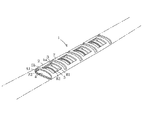
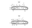
2組づつにて上下の導電線面A1,A2、B1,B2を断続コーティング配線するフィルムスイッチ1は、弾撥性を有すプラスチックフィルムを用いて図1に示すように断面視楕円形状の折り返し曲げにて細く長い形状にて形成し、上片2に窓孔3を並設して各窓孔3内に下片4端より円曲折り返しする有端の細片5を横断させてなり、該細片5は下片4の延長にてなる反撥曲部4aによって上方向に向けて弾発付勢されている。各細片5上には下側導電線面B1,B2の延長部が設けられており、窓孔3より表出する部分は剥離等を防止するために膜体6の重着にて保護して剥離しないようにしている。しかして各細片5の先部は2股に拡げ分けして2つのベース5a,5bを形成し、それぞれの上面に架橋用端子面C1,C2を設けている。下側導電線面B1,B2は上側導電線面A1,A2の断続部に相対して設けられていて、且つ端子面C1,C2につながっている。
なお、端子面C1,C2は上側導電線面A1,A2下にあって窓孔3より表出しないようになっている。
The film switch 1 for intermittently coating the upper and lower conductive wire surfaces A1, A2, B1, and B2 in two sets is folded back in an elliptical shape in cross section as shown in FIG. 1 using a plastic film having elasticity. Formed in a thin and long shape by bending, the
The terminal surfaces C1 and C2 are below the upper conductive line surfaces A1 and A2 and are not exposed from the
形成されたフィルムスイッチ1は使用箇所に張設するのである。いずれかの細片5を上方から押し下降すると端子面C1,C2は下降して上片2の内面に設けた上側導電線面A1,A2から離れて導電を遮断してスイッチをOFFとし、押しを解くと細片5の弾撥上動にて端子面C1,C2が上側導電線面A1,A2の断続部に同時に戻り架橋して通電状態となる。
The formed
この間、2組の架橋用端子面C1,C2は細片5の先部を2股に拡げ分けしたことによって均等に、すなわちねじれなしに上下動して確実にON,OFFのスイッチ作用を行うこととなる。
During this time , the two sets of bridging terminal surfaces C1 and C2 are moved up and down evenly, that is, without twisting, by switching the tip portion of the
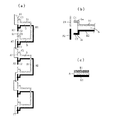
上側導電線面と下側導電線面は図3(c)に示すように交叉する個所では絶縁材8によるコーティング面を挟んで配線コーティングするものであり、図4に示すように交叉なしにて配線コーティングすることもできる。
As shown in FIG. 3C, the upper conductive line surface and the lower conductive line surface are subjected to wiring coating with the coating surface of the
フィルムスイッチ1はゴムなどの保護コード(図示してない)に通すこともでき、裸のままにて使用箇所に張設することもできる。
The
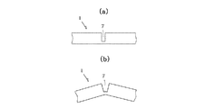
なお、フィルムスイッチ1は上面に設けた曲折用の細溝7をもとにして図7(b)に示すように折り曲げ張設することができる。
The
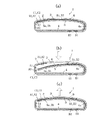
フィルムスイッチ1は常態では、図2(a),図3(a)に示すように有端の細片5の反撥上動によって2組づつの上側導電線面A1,A2と下側導電線面B1,B2はそれぞれ架橋して導電状態を保っているが、図2(b)に矢印で示すように並列窓孔3下のひとつの細片5を押して下降させるとその細片5の架橋用端子面C1,C2は図3(b)に示すように上側導電線面A1,A2より離れて導電を遮断することとなる。どの位置の細片5を押し下降しても2組の上側導電線面はその全長において非導電となり、押しが解かれると図2(c)に示すように細片5の弾撥上動によって架橋用端子面C1,C2は上側導電線面A1,A2の断続部に戻り架橋して通電状態となる。
As shown in FIGS. 2 (a) and 3 (a), the
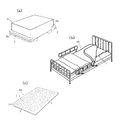
本発明のフィルムスイッチ1は導電の遮断を検知した信号によって警報を発し、また自動停止の制御に役立てるのである。曲げることができることから、図8(a)に示すように例えば無人搬送車9のバンパー9aに取付けてバンパースイッチとして使用することもできる。
The film switch 1 of the present invention issues an alarm by a signal that detects the interruption of electrical conduction, and is useful for control of automatic stop. Since it can be bent, as shown in FIG. 8A, it can be attached to the
また図8(b)に示すようにフィルムスイッチ1をベッド10上に敷いてベッドセンサーとして使用するのである。患者がベッド10上にいるとその押圧によって細片5は押されて2組の上側導電線面A1,A2から離れて絶縁しているが、患者がベッド10から落ちたり不在になると細片5の架橋用端子面C1,C2が2組の上側導電線面に反撥接触して導電状態とするので警報(図示してない)等が作動して患者の不在をしかるべき部署に知らせることとなる。
Further, as shown in FIG. 8B, the
またフィルムスイッチ1を多数本並列することで、図8(c)に示すように検知範囲の広く大きいマットスイッチ11にすることもできる。
Further, by arranging a large number of
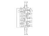
図9は第2実施例を示すもので、2股のベース5a,5bにベース5aを上、ベース5bを下とする上下の段差を設け、架橋用端子面C1は上側ベース5aの上面のまま、架橋用端子面C2を下側ベース5bの下面に配し、2組の上側導電線面のうちのA1は上片2の内面のまま、一方のA2を架橋用端子面C2に相対する位置の下片4上に配設してなり、常態で架橋用端子面C1が導電線面A1に接面してONとなっているときに架橋用端子面C2は導電線面A2と離れてOFF状態であり、細片5を押し下降して架橋用端子面C1が導電線面A1から離れてOFFとなるときに下面の架橋用端子面C2が導電線面A2に接面してON状態となり、押しの解除にて上側が再びONとなるときに下側がOFFとなるようにしたものである。なおこの実施例のフィルムスイッチ1は、全長に並設するすべての細片5が同時に押し下降されて下面の架橋用端子面の全部が架橋導電し、細片5の押しが全部同時に解除されて上面の架橋用端子面のすべてが架橋導電となる状況において使用することができる。また図10に示すように、導電線面A2の全長と端子面C2に連なる導電線面B2の全長を断続することなく連続させることによって、いずれか1つの細片5が押し下降されたときにもON状態となり、押しの解除によりOFF状態となるようにすることもできる。このようにして2組の回路のうちいずれか一方が導電状態となることによって異なる構成の安全回路用として使用できるものとなる。
Figure 9 shows a second embodiment, bifurcated
本発明は、フィルムスイッチに2組の独立した回路を有せしめて、該2組の回路を押し下降により同時に非導電、押しの解除により同時に導電常態とするスイッチ作用または押し下降により同時に開と閉、押しの解除により同時に閉と開とにスイッチ作用するようにして冗長性を持たせたので、安全性の高い回路用スイッチとして長期に亘り断線のないスイッチとして広範に利用することができるものである。 In the present invention, the film switch has two sets of independent circuits, and the two sets of circuits are simultaneously made non-conductive by pushing down, and simultaneously opened and closed by making a switch action or pushing down to make the conductive state normal by releasing the push. Since the switch is operated to be closed and opened at the same time by releasing the push, it has redundancy, so it can be widely used as a switch for high safety without disconnection for a long time. is there.
1はフィルムスイッチ
2は上片
3は窓孔
4は下片
4aは弾発曲部
5は細片
5a,5bは2股に拡げ分けしたベース
6は膜体
7は細溝
8は絶縁材
9は無人搬送車
9aはバンパー
10はベッド
11はマットスイッチ
A1,A2は上側導電線面
B1,B2は下側導電線面
C1,C2は架橋用端子面
1 is a film switch, 2 is an upper piece, 3 is a window hole, 4 is a lower piece, 4a is an elastically bent portion, 5 is a thin piece, 5a and 5b are divided into two forks, 6 is a film body, 7 is a narrow groove, and 8 is an insulating material. upper Gawashirube wire
Claims (2)
Priority Applications (1)
| Application Number | Priority Date | Filing Date | Title |
|---|---|---|---|
| JP2006177661A JP4671237B2 (en) | 2006-06-28 | 2006-06-28 | Film switch |
Applications Claiming Priority (1)
| Application Number | Priority Date | Filing Date | Title |
|---|---|---|---|
| JP2006177661A JP4671237B2 (en) | 2006-06-28 | 2006-06-28 | Film switch |
Publications (2)
| Publication Number | Publication Date |
|---|---|
| JP2008010235A JP2008010235A (en) | 2008-01-17 |
| JP4671237B2 true JP4671237B2 (en) | 2011-04-13 |
Family
ID=39068256
Family Applications (1)
| Application Number | Title | Priority Date | Filing Date |
|---|---|---|---|
| JP2006177661A Expired - Fee Related JP4671237B2 (en) | 2006-06-28 | 2006-06-28 | Film switch |
Country Status (1)
| Country | Link |
|---|---|
| JP (1) | JP4671237B2 (en) |
Families Citing this family (1)
| Publication number | Priority date | Publication date | Assignee | Title |
|---|---|---|---|---|
| WO2012053599A1 (en) * | 2010-10-20 | 2012-04-26 | 山陰制御有限会社 | Device for ascertaining if patients get out of bed |
Family Cites Families (4)
| Publication number | Priority date | Publication date | Assignee | Title |
|---|---|---|---|---|
| JPS60194832A (en) * | 1984-03-16 | 1985-10-03 | Fujitsu Ltd | Squelch circuit |
| JP2553680Y2 (en) * | 1992-06-05 | 1997-11-12 | 株式会社東京センサ | Mat switch |
| JP2003031916A (en) * | 2001-07-19 | 2003-01-31 | Alps Electric Co Ltd | Printed wiring board |
| JP4416573B2 (en) * | 2004-05-31 | 2010-02-17 | 株式会社アイデル | Film switch with spring repulsion |
-
2006
- 2006-06-28 JP JP2006177661A patent/JP4671237B2/en not_active Expired - Fee Related
Also Published As
| Publication number | Publication date |
|---|---|
| JP2008010235A (en) | 2008-01-17 |
Similar Documents
| Publication | Publication Date | Title |
|---|---|---|
| CN101331570B (en) | keyboard | |
| CN100431879C (en) | Seating sensor having film switch and resistor element | |
| CN101501364A (en) | Hinge element for an energy-conducting chain | |
| CN100576400C (en) | slide-operated switch | |
| BRPI0714397A8 (en) | DIAGNOSTIC TEST STRIPS AND METHOD OF PRODUCING THEM PLURALITY | |
| US20130194710A1 (en) | Thermal overload protection apparatus | |
| US4967043A (en) | Absorbing overtravel in sequential switching | |
| JP4671237B2 (en) | Film switch | |
| SE8506085D0 (en) | SYNCHRONOUSLY OPERABLE ELECTRICAL CURRENT SWITCHING APPARATUS HAVING MULTIPLE CIRCUIT SWITCHING CAPABILITY AND / OR REDUCED CONTACT RESISTANCE | |
| US5530318A (en) | EL lamp with integral fuse and connector | |
| ATE492926T1 (en) | CONNECTION DEVICE AND CONNECTION SYSTEM FOR INSULATED ELECTRICAL CONDUCTORS | |
| KR20130143600A (en) | Contact structure | |
| US6046413A (en) | Switch with lift-off ramp | |
| CN100521019C (en) | Switch array | |
| JPH0447934B2 (en) | ||
| JP4545635B2 (en) | Film switch | |
| JPH07503575A (en) | switch mat or switch board | |
| US6455793B1 (en) | Continuous-length switch | |
| JPH10200641A (en) | Call system | |
| US486212A (en) | Circuit-controller | |
| JP6985451B2 (en) | Electric switchgear with shape memory element | |
| JP4416573B2 (en) | Film switch with spring repulsion | |
| CN215867158U (en) | Material breakage detection device and material breakage detection circuit | |
| KR100366826B1 (en) | Switch using wire | |
| WO2005069461A3 (en) | Safety device, in particular for ensuring protection of a loom of cables |
Legal Events
| Date | Code | Title | Description |
|---|---|---|---|
| A621 | Written request for application examination |
Free format text: JAPANESE INTERMEDIATE CODE: A621 Effective date: 20090113 |
|
| A977 | Report on retrieval |
Free format text: JAPANESE INTERMEDIATE CODE: A971007 Effective date: 20101125 |
|
| A131 | Notification of reasons for refusal |
Free format text: JAPANESE INTERMEDIATE CODE: A131 Effective date: 20101129 |
|
| A521 | Request for written amendment filed |
Free format text: JAPANESE INTERMEDIATE CODE: A523 Effective date: 20101214 |
|
| TRDD | Decision of grant or rejection written | ||
| A01 | Written decision to grant a patent or to grant a registration (utility model) |
Free format text: JAPANESE INTERMEDIATE CODE: A01 Effective date: 20110112 |
|
| A01 | Written decision to grant a patent or to grant a registration (utility model) |
Free format text: JAPANESE INTERMEDIATE CODE: A01 |
|
| A61 | First payment of annual fees (during grant procedure) |
Free format text: JAPANESE INTERMEDIATE CODE: A61 Effective date: 20110112 |
|
| R150 | Certificate of patent or registration of utility model |
Ref document number: 4671237 Country of ref document: JP Free format text: JAPANESE INTERMEDIATE CODE: R150 Free format text: JAPANESE INTERMEDIATE CODE: R150 |
|
| FPAY | Renewal fee payment (event date is renewal date of database) |
Free format text: PAYMENT UNTIL: 20140128 Year of fee payment: 3 |
|
| R250 | Receipt of annual fees |
Free format text: JAPANESE INTERMEDIATE CODE: R250 |
|
| R250 | Receipt of annual fees |
Free format text: JAPANESE INTERMEDIATE CODE: R250 |
|
| R250 | Receipt of annual fees |
Free format text: JAPANESE INTERMEDIATE CODE: R250 |
|
| R250 | Receipt of annual fees |
Free format text: JAPANESE INTERMEDIATE CODE: R250 |
|
| R250 | Receipt of annual fees |
Free format text: JAPANESE INTERMEDIATE CODE: R250 |
|
| R250 | Receipt of annual fees |
Free format text: JAPANESE INTERMEDIATE CODE: R250 |
|
| R250 | Receipt of annual fees |
Free format text: JAPANESE INTERMEDIATE CODE: R250 |
|
| R250 | Receipt of annual fees |
Free format text: JAPANESE INTERMEDIATE CODE: R250 |
|
| R250 | Receipt of annual fees |
Free format text: JAPANESE INTERMEDIATE CODE: R250 |
|
| R250 | Receipt of annual fees |
Free format text: JAPANESE INTERMEDIATE CODE: R250 |
|
| LAPS | Cancellation because of no payment of annual fees |