JP4671076B2 - Superheated steam heater - Google Patents
Superheated steam heater Download PDFInfo
- Publication number
- JP4671076B2 JP4671076B2 JP2007543637A JP2007543637A JP4671076B2 JP 4671076 B2 JP4671076 B2 JP 4671076B2 JP 2007543637 A JP2007543637 A JP 2007543637A JP 2007543637 A JP2007543637 A JP 2007543637A JP 4671076 B2 JP4671076 B2 JP 4671076B2
- Authority
- JP
- Japan
- Prior art keywords
- superheated steam
- heater
- annular container
- water
- water tank
- Prior art date
- Legal status (The legal status is an assumption and is not a legal conclusion. Google has not performed a legal analysis and makes no representation as to the accuracy of the status listed.)
- Expired - Fee Related
Links
Images


Classifications
-
- F—MECHANICAL ENGINEERING; LIGHTING; HEATING; WEAPONS; BLASTING
- F24—HEATING; RANGES; VENTILATING
- F24F—AIR-CONDITIONING; AIR-HUMIDIFICATION; VENTILATION; USE OF AIR CURRENTS FOR SCREENING
- F24F6/00—Air-humidification, e.g. cooling by humidification
- F24F6/18—Air-humidification, e.g. cooling by humidification by injection of steam into the air
-
- F—MECHANICAL ENGINEERING; LIGHTING; HEATING; WEAPONS; BLASTING
- F24—HEATING; RANGES; VENTILATING
- F24H—FLUID HEATERS, e.g. WATER OR AIR HEATERS, HAVING HEAT-GENERATING MEANS, e.g. HEAT PUMPS, IN GENERAL
- F24H3/00—Air heaters
- F24H3/02—Air heaters with forced circulation
- F24H3/04—Air heaters with forced circulation the air being in direct contact with the heating medium, e.g. electric heating element
-
- F—MECHANICAL ENGINEERING; LIGHTING; HEATING; WEAPONS; BLASTING
- F24—HEATING; RANGES; VENTILATING
- F24H—FLUID HEATERS, e.g. WATER OR AIR HEATERS, HAVING HEAT-GENERATING MEANS, e.g. HEAT PUMPS, IN GENERAL
- F24H6/00—Combined water and air heaters
Description
本発明は、過熱水蒸気暖房機に関し、更に詳しくは、環境に優しく、省エネルギーを実現することができる過熱水蒸気暖房機に関するものである。 The present invention relates to a superheated steam heater, and more particularly, to a superheated steam heater that is environmentally friendly and can realize energy saving.
従来の暖房機としては、例えば温風ファンヒータや石油ファンヒータが汎用されている。 As a conventional heater, for example, a warm air fan heater or an oil fan heater is widely used.
温風ファンヒータは、空気を加熱するヒータと、ヒータで加熱された空気を送風するファンと、これらを収納する筐体と、を備え、ヒータによって筐体内の空気を加熱した後、ファンによって筐体内から外部へ加熱空気を送風することによって室内を暖房するようにしている。 The hot air fan heater includes a heater that heats air, a fan that blows air heated by the heater, and a housing that houses these. After the air in the housing is heated by the heater, The interior of the room is heated by blowing heated air from the body to the outside.
また、石油ファンヒータは、石油を貯留するタンクと、タンクから供給される石油を燃焼させるバーナーと、バーナーによって加熱された空気を送風するファンと、これらの収納する筐体と、を備え、ファンによってバーナーで加熱された空気を筐体内から外部へ送風することによって室内を暖房するようにしている。 The oil fan heater includes a tank that stores oil, a burner that burns oil supplied from the tank, a fan that blows air heated by the burner, and a housing that stores these fans. The room is heated by blowing air heated by a burner from the inside of the housing to the outside.
しかしながら、従来の温風ファンヒータの場合には、ヒータによって空気を加熱し、空気を更に乾燥させた状態で室内へ送風するため、室内の空気が乾燥する上に、温風の熱容量が小さく、暖房効率が悪い。また、石油ファンヒータの場合には、石油を燃焼して二酸化炭素が発生するため、室内の換気が必要であり、更に、二酸化炭素により環境に負荷がかかり、地球温暖化の観点に立つと極力環境負荷の少ない暖房機が望まれる。 However, in the case of the conventional hot air fan heater, the air is heated by the heater and blown into the room with the air further dried, so the indoor air is dried and the heat capacity of the hot air is small, Heating efficiency is poor. In the case of an oil fan heater, oil is burned and carbon dioxide is generated. Therefore, indoor ventilation is necessary, and the environment is further affected by carbon dioxide. From the viewpoint of global warming, it is as much as possible. A heater with low environmental impact is desired.
本発明は、上記課題を解決するためになされたもので、二酸化炭素を発生することがなくて環境に優しく、しかも暖房効率に優れ、省エネルギーを実現することができる過熱水蒸気暖房機を提供することを目的としている。 The present invention has been made to solve the above problems, and provides an overheated steam heater that does not generate carbon dioxide, is environmentally friendly, has excellent heating efficiency, and can realize energy saving. It is an object.
本発明の請求項1に記載の過熱水蒸気暖房機は、水を供給する水供給部と、この水供給部から供給される水を用いて過熱水蒸気を発生させる過熱水蒸気発生部と、この過熱水蒸気発生部において発生する過熱水蒸気を送り出す送風機と、を備え、上記過熱水蒸気発生部は、上記水供給部から上記水を受給する環状容器と、この環状容器の内側に配置されたヒータと、を有し、上記環状容器の環状の上面には上記過熱水蒸気が吐出する複数の孔が周方向に等間隔を空けて形成されており、上記送風機によって送風される上記過熱水蒸気によって暖房することを特徴とするものである。 The superheated steam heater according to claim 1 of the present invention includes a water supply unit that supplies water, a superheated steam generation unit that generates superheated steam using water supplied from the water supply unit, and the superheated steam. A blower that sends out superheated steam generated in the generator, and the superheated steam generator has an annular container that receives the water from the water supply part, and a heater disposed inside the annular container. A plurality of holes through which the superheated steam is discharged are formed at equal intervals in the circumferential direction on the annular upper surface of the annular container, and heating is performed by the superheated steam blown by the blower. To do.
また、本発明の請求項2に記載の過熱水蒸気暖房機は、請求項1に記載の発明において、上記ヒータは上記環状容器の内周面全面に渡って螺旋状に形成されており、且つ、上記ヒータの上端が上記環状容器の上端から突出していることを特徴とするものである。 The superheated steam heater according to claim 2 of the present invention is the superheated steam heater according to claim 1 , wherein the heater is formed in a spiral shape over the entire inner peripheral surface of the annular container, and The upper end of the heater protrudes from the upper end of the annular container.
本発明によれば、二酸化炭素を発生することがなくて環境に優しく、しかも暖房効率に優れ、省エネルギーを実現することができる過熱水蒸気暖房機を提供することができる。 According to the present invention, it is possible to provide an overheated steam heater that does not generate carbon dioxide, is environmentally friendly, has excellent heating efficiency, and can realize energy saving.
10 過熱水蒸気暖房機
11 水供給部
12 過熱水蒸気発生部
13 送風機
14 筐体
121 環状容器
121E 孔
122 ヒータDESCRIPTION OF
以下、図1〜図4に示す実施形態に基づいて本発明を説明する。 Hereinafter, the present invention will be described based on the embodiment shown in FIGS.
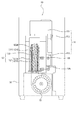
本実施形態の過熱水蒸気暖房機10は、例えば図1、図2に示すように、水Wを供給する水供給部11と、この水供給部11から供給される水Wを用いて過熱水蒸気Sを発生させる過熱水蒸気発生部12と、この過熱水蒸気発生部12において発生する過熱水蒸気Sを送り出す送風機13と、これらの機器を収納する筐体14と、を備え、筐体14の送風口14Aと過熱水蒸気発生部12がダクト15を介して連通し、過熱水蒸気発生部12において発生する過熱水蒸気Sを送風機13によって送風口14Aから外部、即ち室内へ送風するように構成されている。
For example, as shown in FIGS. 1 and 2, the
筐体14は、図1の(a)〜(c)に示すように縦長の略直方体を呈し、その正面に送風口14Aが形成され、左右両側面に取っ手14Bが形成されている。また、筐体14の上面には図1の(a)に示すように後述する水タンクを出し入れする開口部が形成され、この開口部はヒンジ付きの片開きの蓋14Cによって開閉できるようになっている。また、筐体14の上面には電源スイッチ14D、温度設定スイッチ14E等の暖房機に必要な操作スイッチや温度表示部等が取り付けられている。
As shown in FIGS. 1A to 1C, the
而して、水供給部11は、過熱水蒸気発生部12へ水Wを供給する機能があれば良く、特定の構造に制限されるものではない。本実施形態における水供給部11は、例えば図2、図3に示すように、カートリッジ式の水タンク111と、水タンク111を保持するホルダー112と、ホルダー112で保持された水タンク111の下側に配置された固定水タンク113と、を有し、固定水タンク113から過熱水蒸気発生部11へ水Wを直接供給するように構成されている。水タンク111の水供給口にはバルブ(図示せず)を内蔵する口栓111Aが螺合している。また、固定水タンク113には水タンク111の口栓111Aが嵌合する嵌合部113Aが形成され、水タンク111がホルダー112に装着されると、水タンク111の口栓111Aが固定水タンク113の嵌合部113Aに嵌合すると共に嵌合部113Aに装着されたピン(図示せず)で口栓111Aのバルブが開き、水タンク111から固定水タンク113へ水Wが供給される。口栓111Aのバルブが固定水タンク113の水によって塞がれると、水タンク111側へ空気が入らないため、水タンク111から固定水タンク113への水の供給が停止される。水タンク111の口栓111A及び固定水タンク112の嵌合部113Aは、従来公知のものである。
Thus, the
尚、本実施形態では、水タンク111から固定水タンク113へ水Wを供給するようにしているが、例えば水道水を固定水タンク113へ直接供給するようにしても良い。
In the present embodiment, the water W is supplied from the
過熱水蒸気発生部12は、水供給部11から水Wを受給して過熱水蒸気Sを発生する機能があれば良く、特定の構造に制限されるものではない。本実施形態における過熱水蒸気発生部12は、図2、図3に示すように、固定水タンク113から水Wを受給する環状容器121と、この環状容器121の内側に配置されたヒータ122と、を有し、環状容器121内の水Wを内側のヒータ122によって加熱して過熱水蒸気Sを発生させるように構成されている。環状容器121は、図4に示すように、外筒121Aと、外筒121Aより小径に形成された内筒121Bと、外筒121Aの下端と内筒121Bの下端を連結する環状の下面(図示せず)と、外筒121Aの上端と内筒121Bの上端を連結する環状の上面121Cと、を有し、外筒121Aと内筒121Bの間の空間121D(図4参照)において固定水タンク113から受給する水Wから過熱水蒸気を発生させるように形成されている。この環状容器121の環状の上面121Cには、図4に示すように周方向に等間隔を空けて複数の孔121Eが形成され、外筒121Aと内筒121B間の空間121Dで発生する過熱水蒸気Sが図2に示すように上面121Cの複数の孔121Eから吐出するようになっている。
The superheated
そして、環状容器121と固定水タンク113は、図2、図3に示すように、上下に配置された第1、第2の配管16A、16Bを介して互いに接続されている。第1の配管16Aの一端は固定水タンク113の下面に接続され、その他端は環状容器121の外筒121Aの下部に接続されている。第2の配管16Bの一端は固定水タンク113の側面に接続され、その他端は外筒121Aの上部近傍に接続されている。第1、第2の配管16A、16Bを上下に配置することによって、水タンク111内の水Wを使い果たし、固定水タンク113内の水が少なくなって第2の配管16Bのレベルより水位が低くなっても環状容器121の空間121Dと固定水タンク113の空間とが第2の配管16を介して連通しているため、環状容器121内の過熱水蒸気Sが第2の配管16Bから固定水タンク113内へ流入し、環状容器121内と固定水タンク113内が等圧になって環状容器121内の水位を一定に保つようになっている。暖房により固定水タンク113の水がなくなったら、ヒータ122の電源が自動的に切断されるようになっている。
And the
ヒータ122は、環状容器121内の水Wから過熱水蒸気Sを発生させるように環状容器121を加熱する機能があればよく、特に制限されるものではない。本実施形態におけるヒータ122は、図2〜図4に示すように、環状容器121の内筒121Bの下端から上方に向けて螺旋状に巻き上げて内筒121Bの全面を被覆するよう形成されており、その上端が環状容器121の上端から突出している。このようにヒータ122で環状容器121全体をその内側から加熱することによって環状容器121内で過熱水蒸気Sを確実に発生させることができる。更に、環状容器121の複数の孔121Eから吐出する過熱水蒸気Sを環状容器121の上端から突出するヒータ122の突出部122Aによって加熱することによって過熱水蒸気Sを更に昇温させて、例えば過熱水蒸気Sを200℃前後に昇温することによって過熱水蒸気Sの熱容量を高め、暖房効率を高めるようにしてある。本実施形態ではヒータ122として例えばシーズヒータを用いている。ヒータ122は、筐体14の上面に設けられた温度設定スイッチ14Fによって適宜の温度に設定することができる。
The
尚、本実施形態ではヒータ122としてシーズヒータを用いているが、シーズヒータに制限されないことは云うまでもない。
In the present embodiment, a sheathed heater is used as the
また、送風機13は、図2、図3に示すように例えばターボファンによって形成され、過熱水蒸気発生部12の下方に配置されている。この送風機13の回転軸12Aは固定水タンク113の下方に配置された電気モータ17の回転軸の一端に連結され、電気モータ17によって回転して環状容器121の内側のヒータ122が配置された空間へ空気を送風するようにしてある。また、電気モータ17の回転軸の他端には固定水タンク113の下方に配置されたファン(例えば、プロペラファン)18に連結され、筐体14の背面の下部に形成された空気取り入れ口(図示せず)から外部の空気を吸引すると共に電気モータ17を冷却するようにしてある。
Further, as shown in FIGS. 2 and 3, the
送風機13によって環状容器122の内側に送風された空気は、そこでヒータ122によって加熱される。この加熱空気は、環状容器122の上面121Dの複数の孔121Eから吐出する過熱水蒸気Sと混合される。混合された過熱水蒸気Sと加熱空気は、環状容器121のダクト15を介して筐体14の送風口14Aへ誘導されて、送風口14Aから外部へ排出されて暖房に供される。
The air blown into the
過熱蒸気発生部12において発生する過熱水蒸気Sは、熱容量が大きく、乾燥しており、しかも熱伝達性に優れているため、室内へ排出されても加熱空気と一緒に室内全体へ拡散して室内を効率良く暖房することができると共に室内を加湿するものの壁面等に結露することがない。従って、過熱水蒸気暖房機10以外に加湿器を設ける必要もなく、室内の乾燥を確実に防止することができる。更に、過熱水蒸気Sは、遠赤外線を放射するため、体に優しい暖房を行うことができる。
The superheated steam S generated in the
次に、動作について説明する。過熱水蒸気暖房機10を所望の場所に配置する。そして、水供給部11のカートリッジ式の水タンク111に水Wを満たし、筐体14の蓋14Dを開けて水タンク111を筐体14内のホルダー112へ装着して蓋14Cを閉じる。水タンク111内の水Wは、口栓111Aから固定水タンク113内へ流入し、固定水タンク113内に水Wが満たされると共に固定水タンク113から過熱水蒸気発生部12の環状容器121内へ水Wが流入し、水タンク111から固定水タンク113への水の供給が停止する。
Next, the operation will be described. The
次いで、電源スイッチ14Dを操作して電源を投入すると、電気モータ17が駆動すると共にヒータ122が作動する。電動モータ17の駆動により送風機17が回転して筐体14内の空気をヒータ122へ送風する。同時にプロペラファン18によって外部から筐体14内へ空気を吸引して電気モータ17を冷却すると共に送風機13側へ空気を補充する。
Next, when the power switch 14D is operated to turn on the power, the
過熱水蒸気発生部12のヒータ122が作動すると、環状容器121内の水Wが加熱されて水蒸気が発生する。この水蒸気は環状容器121内でヒータ122によって更に加熱されて過熱水蒸気Sとなって環状容器121の複数の孔121Eから上方へ吐出する。この際、送風機13によって送風される空気をヒータ122によって加熱し、加熱空気と過熱水蒸気Sがダクト15を通過する間に混合されて筐体14の送風口14Aから室内へ供給される。
When the
暖房の間に水タンク111の水Wが使い果たされ、固定水タンク113内の水位が第2の配管16Bより低下しても、環状容器121と固定水タンク113は第2の配管16Bを介して連通するため、環状容器121内と固定水タンク113内が等圧になって環状容器121内の水位を一定に保つ。固定水タンク113内の水Wがなくなると電源が自動的に切断されて、ヒータ122によって環状容器121の空焚きを防止する。
Even if the water W in the
以上説明したように本実施形態によれば、過熱水蒸気暖房機10は、水Wを供給する水供給部11と、この水供給部11から供給される水Wを用いて過熱水蒸気Sを発生させる過熱水蒸気発生部12と、この過熱水蒸気発生部12において発生する過熱水蒸気Sを送り出す送風機13と、これらの機器11、12、13を収納する筐体14と、を備え、過熱水蒸気発生部12は、水供給部11から水Wを受給する環状容器121と、この環状容器121の内側に配置されたヒータ122と、を有し、環状容器121の環状の上面121Cには過熱水蒸気Sが吐出する複数の孔121Eが周方向に等間隔を空けて形成されており、送風機13によって過熱水蒸気発生部12において発生する過熱水蒸気Sを送風口14Aから外部へ送風して暖房するように構成されているため、過熱水蒸気発生部12において環状容器121の内側に配置されたヒータ122により環状容器121内で過熱水蒸気Sを確実に発生させ、過熱水蒸気Sを複数の孔121Eから吐出させると共に、送風機13を介して過熱水蒸気Sと加熱空気と混合して送風することができ、その結果、石油等の燃焼による二酸化炭素の発生がなく、環境に優しい暖房を行うことができると共に、過熱水蒸気Sによって室内を乾燥させることなく、効率良く短時間で室内を暖房することができる。また、過熱水蒸気Sは遠赤外線を放射するため、体に優しい暖房を行うことができる。また、本実施形態によれば、暖房効率が良く、石油等の燃料を使用しないため、環境負荷がなく、省エネルギーを促進することができ、電気代を節約することができる。
As described above, according to the present embodiment, the
また、本実施形態によれば、ヒータ122は環状容器121の内周面全面に沿って螺旋状に形成されており、且つ、ヒータ122の上端が環状容器121の上端から突出しているため、ヒータ122の突出部122Aによって環状容器121の複数の孔121Eから吐出する過熱水蒸気Sを更に加熱して熱容量の大きな過熱水蒸気Sを得ることができ、暖房効率を更に高めることができる。
Further, according to the present embodiment, the
尚、本発明は上記実施形態になんら制限されるものではなく、必要に応じて各構成要素を適宜設計変更することができる。 In addition, this invention is not restrict | limited to the said embodiment at all, and can change the design of each component suitably as needed.
本発明は、家庭用の暖房機は勿論のこと、温室栽培用のビニールハウス等の産業用の暖房機として好適に利用することができる。 INDUSTRIAL APPLICABILITY The present invention can be suitably used not only as a home heater but also as an industrial heater such as a greenhouse for greenhouse cultivation.
Claims (2)
上記過熱水蒸気発生部は、上記水供給部から上記水を受給する環状容器と、この環状容器の内側に配置されたヒータと、を有し、上記環状容器の環状の上面には上記過熱水蒸気が吐出する複数の孔が周方向に等間隔を空けて形成されており、
上記送風機によって送風される上記過熱水蒸気によって暖房することを特徴とする過熱水蒸気暖房機。A water supply unit that supplies water, a superheated steam generation unit that generates superheated steam using water supplied from the water supply unit, and a blower that sends out superheated steam generated in the superheated steam generation unit,
The superheated steam generation unit includes an annular container that receives the water from the water supply unit, and a heater disposed inside the annular container, and the superheated steam is formed on an annular upper surface of the annular container. A plurality of holes to be discharged are formed at equal intervals in the circumferential direction,
The superheated steam heater, which is heated by the superheated steam blown by the blower.
Applications Claiming Priority (1)
| Application Number | Priority Date | Filing Date | Title |
|---|---|---|---|
| PCT/JP2007/051789 WO2008096395A1 (en) | 2007-02-02 | 2007-02-02 | Superheated steam heater |
Publications (2)
| Publication Number | Publication Date |
|---|---|
| JPWO2008096395A1 JPWO2008096395A1 (en) | 2010-05-20 |
| JP4671076B2 true JP4671076B2 (en) | 2011-04-13 |
Family
ID=39681316
Family Applications (1)
| Application Number | Title | Priority Date | Filing Date |
|---|---|---|---|
| JP2007543637A Expired - Fee Related JP4671076B2 (en) | 2007-02-02 | 2007-02-02 | Superheated steam heater |
Country Status (3)
| Country | Link |
|---|---|
| JP (1) | JP4671076B2 (en) |
| KR (1) | KR20100004995A (en) |
| WO (1) | WO2008096395A1 (en) |
Families Citing this family (2)
| Publication number | Priority date | Publication date | Assignee | Title |
|---|---|---|---|---|
| KR101255112B1 (en) | 2012-11-05 | 2013-04-19 | 김현구 | Sterilization heater using super-heated steam |
| JP2019219103A (en) * | 2018-06-20 | 2019-12-26 | 株式会社サンエス | Overheated steam generator and heating appliance using the same |
Citations (6)
| Publication number | Priority date | Publication date | Assignee | Title |
|---|---|---|---|---|
| JPS5762335A (en) * | 1980-10-02 | 1982-04-15 | Ishikawajima Harima Heavy Ind Co Ltd | Hot air heater with waste heat recovery type humidifier |
| JPS63167725A (en) * | 1986-12-30 | 1988-07-11 | 小原 康範 | Apparatus for humidifying and heating artificial environment |
| JPH03122295U (en) * | 1990-03-26 | 1991-12-13 | ||
| JP2002106801A (en) * | 2000-09-29 | 2002-04-10 | Daihan:Kk | Steam generator |
| JP2004205146A (en) * | 2002-12-26 | 2004-07-22 | Fuji Electric Fa Components & Systems Co Ltd | Steam generator |
| JP2005144144A (en) * | 2003-10-23 | 2005-06-09 | Seta Giken Co Ltd | Steaming chamber and method to control steaming room |
Family Cites Families (1)
| Publication number | Priority date | Publication date | Assignee | Title |
|---|---|---|---|---|
| JP3122295U (en) * | 2006-03-28 | 2006-06-08 | 寿美 信田 | Heating system |
-
2007
- 2007-02-02 KR KR1020097018332A patent/KR20100004995A/en active Search and Examination
- 2007-02-02 WO PCT/JP2007/051789 patent/WO2008096395A1/en active Application Filing
- 2007-02-02 JP JP2007543637A patent/JP4671076B2/en not_active Expired - Fee Related
Patent Citations (6)
| Publication number | Priority date | Publication date | Assignee | Title |
|---|---|---|---|---|
| JPS5762335A (en) * | 1980-10-02 | 1982-04-15 | Ishikawajima Harima Heavy Ind Co Ltd | Hot air heater with waste heat recovery type humidifier |
| JPS63167725A (en) * | 1986-12-30 | 1988-07-11 | 小原 康範 | Apparatus for humidifying and heating artificial environment |
| JPH03122295U (en) * | 1990-03-26 | 1991-12-13 | ||
| JP2002106801A (en) * | 2000-09-29 | 2002-04-10 | Daihan:Kk | Steam generator |
| JP2004205146A (en) * | 2002-12-26 | 2004-07-22 | Fuji Electric Fa Components & Systems Co Ltd | Steam generator |
| JP2005144144A (en) * | 2003-10-23 | 2005-06-09 | Seta Giken Co Ltd | Steaming chamber and method to control steaming room |
Also Published As
| Publication number | Publication date |
|---|---|
| JPWO2008096395A1 (en) | 2010-05-20 |
| WO2008096395A1 (en) | 2008-08-14 |
| KR20100004995A (en) | 2010-01-13 |
Similar Documents
| Publication | Publication Date | Title |
|---|---|---|
| US9885473B2 (en) | Germicidal heating apparatus using superheated vapor | |
| KR20140007042A (en) | Heater for raising animals and plants | |
| JP4671076B2 (en) | Superheated steam heater | |
| JP2010078249A (en) | Superheated steam heater | |
| JP2009136571A (en) | Hair care apparatus | |
| KR200482794Y1 (en) | Firewood boiler | |
| KR200460879Y1 (en) | humidifier humidifier | |
| KR100824087B1 (en) | A fan for heating and cooling | |
| KR20170133716A (en) | Heating apparatus | |
| KR101746570B1 (en) | Fan heater | |
| KR101821184B1 (en) | Wood boiler | |
| KR20200059728A (en) | Hot-air blower | |
| JP2010127575A (en) | Heat generating device, warm air boiler device, warm water boiler device and steam boiler device | |
| JP2012189305A (en) | High-efficiency heater | |
| KR20090062322A (en) | A steam occurrence device electric heater | |
| KR101540116B1 (en) | A House Heating Unit | |
| KR101269037B1 (en) | Heating apparatus by pipe blower | |
| KR101228241B1 (en) | Firewood boiler | |
| JP2002195614A (en) | Warm air heater | |
| KR100257290B1 (en) | Heating system using waste heat of incinerator | |
| KR100279903B1 (en) | Humidifier of Radiator | |
| KR200281306Y1 (en) | The electric fan for both heating and cooling | |
| KR20080025988A (en) | Self generation a heater | |
| KR200324216Y1 (en) | a heating apparatus mounted with a generator | |
| KR20010054778A (en) | for heating apparatus |
Legal Events
| Date | Code | Title | Description |
|---|---|---|---|
| A131 | Notification of reasons for refusal |
Free format text: JAPANESE INTERMEDIATE CODE: A131 Effective date: 20100615 |
|
| A521 | Request for written amendment filed |
Free format text: JAPANESE INTERMEDIATE CODE: A523 Effective date: 20100816 |
|
| A521 | Request for written amendment filed |
Free format text: JAPANESE INTERMEDIATE CODE: A523 Effective date: 20100824 |
|
| TRDD | Decision of grant or rejection written | ||
| A01 | Written decision to grant a patent or to grant a registration (utility model) |
Free format text: JAPANESE INTERMEDIATE CODE: A01 Effective date: 20101207 |
|
| A01 | Written decision to grant a patent or to grant a registration (utility model) |
Free format text: JAPANESE INTERMEDIATE CODE: A01 |
|
| A61 | First payment of annual fees (during grant procedure) |
Free format text: JAPANESE INTERMEDIATE CODE: A61 Effective date: 20110105 |
|
| R150 | Certificate of patent or registration of utility model |
Ref document number: 4671076 Country of ref document: JP Free format text: JAPANESE INTERMEDIATE CODE: R150 Free format text: JAPANESE INTERMEDIATE CODE: R150 |
|
| FPAY | Renewal fee payment (event date is renewal date of database) |
Free format text: PAYMENT UNTIL: 20140128 Year of fee payment: 3 |
|
| R250 | Receipt of annual fees |
Free format text: JAPANESE INTERMEDIATE CODE: R250 |
|
| R250 | Receipt of annual fees |
Free format text: JAPANESE INTERMEDIATE CODE: R250 |
|
| R250 | Receipt of annual fees |
Free format text: JAPANESE INTERMEDIATE CODE: R250 |
|
| R250 | Receipt of annual fees |
Free format text: JAPANESE INTERMEDIATE CODE: R250 |
|
| R250 | Receipt of annual fees |
Free format text: JAPANESE INTERMEDIATE CODE: R250 |
|
| R250 | Receipt of annual fees |
Free format text: JAPANESE INTERMEDIATE CODE: R250 |
|
| R250 | Receipt of annual fees |
Free format text: JAPANESE INTERMEDIATE CODE: R250 |
|
| R250 | Receipt of annual fees |
Free format text: JAPANESE INTERMEDIATE CODE: R250 |
|
| R250 | Receipt of annual fees |
Free format text: JAPANESE INTERMEDIATE CODE: R250 |
|
| LAPS | Cancellation because of no payment of annual fees |