JP4671071B2 - Pouring device - Google Patents
Pouring device Download PDFInfo
- Publication number
- JP4671071B2 JP4671071B2 JP2000328082A JP2000328082A JP4671071B2 JP 4671071 B2 JP4671071 B2 JP 4671071B2 JP 2000328082 A JP2000328082 A JP 2000328082A JP 2000328082 A JP2000328082 A JP 2000328082A JP 4671071 B2 JP4671071 B2 JP 4671071B2
- Authority
- JP
- Japan
- Prior art keywords
- pouring
- cap
- thin
- tube
- dispensing
- Prior art date
- Legal status (The legal status is an assumption and is not a legal conclusion. Google has not performed a legal analysis and makes no representation as to the accuracy of the status listed.)
- Expired - Fee Related
Links
Images


Landscapes
- Cartons (AREA)
- Closures For Containers (AREA)
Description
【0001】
【発明の属する技術分野】
この発明は、例えば、飲料等を充填した容器の注出装置、とくに、容量300〜500ml程度のスリムな小型容器に適した注出装置に関する。
【0002】
【従来の技術】
この種の注出装置としては、実開平4−80843号公報に開示されているように、容器の頂部に注出筒が設けられ、注出筒内に閉鎖壁が設けられ、閉鎖壁に開口用環状薄肉部が設けられ、薄肉部に近接してその内側に摘みが設けられ、閉鎖壁が、注出筒の下端レベルに位置させられ、摘みが、リング状に形成されているものが知られている。
【0003】
また、別の注出装置としては、実開昭61−11520号公報に開示されているように、容器の頂部に注出筒が設けられ、注出筒内に閉鎖壁が設けられ、閉鎖壁に開口用薄肉部が設けられ、頂部が、左右方向にのびた頂部シールリブを有する切妻屋根型状のものであり、注出筒が、頂部シールリブを挟んでその手前側屋根面上に位置させられ、薄肉部が、頂部シールリブに近い側を開放したU字状に形成され、薄肉部のなすU字の底に近接してその内側に摘みが設けられ、摘みにフックが設けられ、薄肉部を切断してその内側の部分を持上げた際、頂部シールリブにフックが掛止められうるようになされているものが知られている。
【0004】
【発明が解決しようとする課題】
上記前者の注出装置において、とくに、小型容器を対象とする場合、スペースの制約から、注出筒の径が小さくなってしまい、注出口から少量しか注出することができず、注出筒に口をつけて直接飲むには不向きであり、ストローを使用するなどしていた。さらに、注出筒の径が小さくなると摘みのリングの径も小さくなってしまい、薄肉部の切断に際し、小さい径のリングに指を入れることは困難であった。摘みがリング状に形成されている理由は、閉鎖壁が注出筒の下端レベルに位置させられているため、成形時の型抜き上の都合から、そのようにするしか仕方が無いのである。
【0005】
一方、後者の注出装置では、注出筒がキャップ等で被覆されていないため、衛生的ではない。さらに、注出筒に口を付けて飲む際、切断した薄肉部が手前から頂部シールリブの方向に向かって拡がり、その状態でフックが頂部シールリブに掛止められているため、切断した薄肉部に鼻が接触する等の不都合があった。
【0006】
この発明は、比較的小型容器にも好適に利用することができ、十分に注出量を確保することができ、しかも、摘みを摘み易く、注出筒に口を付けて快適にも飲むことができる注出装置を提供することをその目的とするものである。
【0007】
【課題を解決するための手段】
この発明による注出装置は、容器の頂部に注出筒が設けられ、注出筒内に閉鎖壁が設けられ、閉鎖壁に開口用環状薄肉部が設けられ、薄肉部に近接してその内側に摘みが設けられている注出装置において、閉鎖壁が、注出筒の上端レベルに位置させられ、摘みが、舌状に形成されていることを特徴とするものである。
【0008】
この発明による注出装置では、閉鎖壁が、注出筒の上端レベルに位置させられ、摘みが、舌状に形成されているから、摘みをつまみ易い。
【0009】
さらに、薄肉部が、四角形状に形成されていると、閉鎖壁が注出筒の上端レベルに位置させられていることにより、注出方向が定まり難くなりがちであるが、薄肉部を切断した後できた開口の角の部分から注出するようにすれば、注出方向が定まり易くなる。
【0010】
また、注出筒が、横断面長円形状に形成されていると、比較的狭い幅のところにも、長さ方向で注出筒の横断面積を広くとるようにすれば、注出筒の横断面積を大きくすることができる。したがって、十分な注出量を確保することができる。
【0011】
また、注出筒にキャップが着脱自在に被せられていると、注出筒を衛生的に保つことができる。
【0012】
さらに、頂部が、左右方向にのびた頂部シールリブを有する切妻屋根型状のものであり、注出筒が、頂部シールリブを挟んでその手前側屋根面上に位置させられ、薄肉部が、四角形状に形成されてその1つの角を手前に向けており、注出筒が、長さ方向を左右方向に向けた横断面長円形状に形成され、注出筒にキャップが着脱自在に被せられ、注出筒およびキャップが、それぞれの左右いずれかの端部においてヒンジによって連結され、キャップの頂面にフックが設けられ、キャップ開放時のフックが同手前側屋根面におけるヒンジのある側の縁部に掛止められうるようになされていると、切妻屋根型状頂部の狭い領域において、十分に注出量を確保することができ、摘みを容易につまむことができ、しかも、飲む際に、キャップが頂部シールリブにではなく、これと直交する側に倒されてそこに掛け止められるから、キャップが邪魔にならず、注出筒に口を付けて快適にも飲むことができる。
【0013】
【発明の実施の形態】
この発明の実施の形態を図面を参照してつぎに説明する。
【0014】
以下の説明において、図1の矢印Aで示す側を前、これと反対側を後といい、左右とは、前方より見て、その左右の側を左右というものとする。
【0015】
図1を参照すると、容器11は、両面にヒートシール層を有する紙主体積層体製容器素材から組立成形されたもので、角筒状胴部21および切妻屋根型頂部22を有している。頂部22の屋根の棟にあたる部分には上方突出頂部シールリブ23が形成されている。シールリブ23は、左右方向にのびかつ後向きに倒れていて、シールリブ23の手前側屋根面と面一となっている。
【0016】
頂部22は、手前側から順次連なる第1〜第4頂壁パネル31〜34を有している。第1頂壁パネル31および第3頂壁パネル33の内側になるように第2頂壁パネル32および第4頂壁パネル34が内向きひだ状に折り畳まれ、第1頂壁パネル31および第3頂壁パネル33上縁部の間に第2頂壁パネル32および第4頂壁パネル34の上縁部が2つ折りとなって挟み込まれて重ね合わせられて、この重ね合わされた部分がヒートシールされることにより、リブ23が形成されている。
【0017】
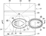
第1頂壁パネル31の中央部には注出口41があけられている。注出口41は、左右方向に長い長円形をなしている。
【0018】
注出口41には注出筒42が備えられている。注出筒42の上端にはキャップ43が着脱自在に被せられている。
【0019】
図4に、注出筒42およびキャップ43の詳細構造があきらかに示されている。図4においては、注出筒42にキャップ43が被せられた状態が鎖線で、注出筒42からキャップ43が外された状態が実線で示されている。
【0020】
注出筒42は、ポリエチレンのような軟質合成樹脂によって一体成型されたもので、注出口41に嵌め入れられている周壁51と、周壁51の下端に連なって設けられかつ注出口41縁部下面にヒートシールされているフランジ52と、周壁51の上端開口を横断するように設けられている閉鎖壁53とよりなる。
【0021】
周壁51は、若干上細りではあるが、注出口41縁部にそって拡がる長円形の横断面をもつ外面を有している。周壁51外面の上端部には環状係合凹部54が形成されている。
【0022】
閉鎖壁53には環状薄肉部55が閉鎖壁下面にV溝56を形成することにより設けられている。薄肉部55は、四角形状に形成されたもので、左右に2つの鋭角と、前後に2つの鈍角をもっている。薄肉部55の鈍角の1つは、手前に向けられている。薄肉部55の右角のすぐ内側からは摘み57が左斜め上向きに立上るように設けられている。摘み57は、薄肉部55の内側部分とほぼ同形状に形成され、これを上側から被覆している。摘み57の上下両面には滑止めリブ58がそれぞれ並列状に設けられている。
【0023】
キャップ43は、平坦状頂壁61と、若干裾拡がりであるが、注出筒42外面にそわされている横断面長円形状のスカート62よりなる。頂壁61の頂面中央には逆L字状フック63が設けられている。スカート62内面下端には環状係合凸部64が形成され、これが係合凹部54にはめ入れられている。閉鎖壁53とキャップ頂壁61の間には、摘み57を軽く押えつけた状態で摘み57を収容しうる間隙が形成されている。
【0024】
注出筒42外面右端部における係合凹部54のすぐ下のレベル部分と、キャップスカート62外面右端部における係合凸部64とほぼ同じレベル部分にまたがってヒンジ71が設けられている。
【0025】
容器11の開封に際し、係合凹部54から係合凸部64を引出してキャップ43を外し、指先で摘み57をつまんで引っ張ると、摘み57の基部付近から薄肉部55が順次切断されていき、薄肉部55が全て切断されると、そこが開口される。摘み57を引っ張る際、リブ58があるため、指先が滑ることもなく、摘み57をしっかりつまむことができる。
【0026】
外したキャップ43は、右側に倒して、丁度裏返しにすると、第1頂壁パネル31の上に重ね合わされるようになる。そして、第1頂壁パネル31右縁とその下側にある第2頂壁パネル32前縁の2倍重ねとされた境界に、フック63が掛け止められる。これにより、注出筒42の開口が全開となった状態でキャップ43が固定される。
【0027】
注出筒42に口を付ける際、注出筒42のなす長円形の手前部分に口をそわせるようにすれは、口あたりも良好である。注出筒42が手前にくるように容器11を傾けて開口から内容物を注出するときに、開口のなす四角形の手前の角の部分が低くなり、その部分から集中的に内容物が注出されるようになるため、内容物の注出方向が定まり易く、内容物がこぼれたりもすることなく、快適に飲むことができる。
【0028】
注出筒42に外したキャップ43を被せ、係合凹部54に係合凸部64をはめ入れると、容器11が再封される。
【0029】
この発明は、上記したゲーブルトップ容器、紙容器のみならず、他の容器にも適用され、とくに、注出筒等を取付るスペースの狭い左右に細長い容器に好適である。
【0030】
【発明の効果】
この発明によれば、比較的小型容器にも好適に利用することができ、十分に注出量を確保することができ、しかも、摘みを摘み易く、注出筒に口を付けて快適にも飲むことができる注出装置が提供される。
【図面の簡単な説明】
【図1】この発明による注出装置の密封状態の斜視図である。
【図2】同注出装置の開封状態の斜視図である。
【図3】同注出装置の開封状態の平面図である。
【図4】図3のIV−IVにそう断面図である。
【符号の説明】
11 容器
22 容器頂部
23 シールリブ
42 注出筒
43 キャップ
53 閉鎖壁
55 薄肉部
57 摘み
63 フック
71 ヒンジ[0001]
BACKGROUND OF THE INVENTION
The present invention relates to, for example, a dispensing device for a container filled with a beverage or the like, and more particularly, to a dispensing device suitable for a slim small container having a capacity of about 300 to 500 ml.
[0002]
[Prior art]
As this kind of pouring device, as disclosed in Japanese Utility Model Publication No. 4-80843, a pouring tube is provided at the top of the container, a closing wall is provided in the pouring tube, and an opening is formed in the closing wall. An annular thin wall portion is provided, a knob is provided in the vicinity of the thin wall portion, a closing wall is positioned at the lower end level of the dispensing cylinder, and the knob is formed in a ring shape. It has been.
[0003]
As another dispensing apparatus, as disclosed in Japanese Utility Model Laid-Open No. 61-11520, a dispensing cylinder is provided at the top of the container, and a closing wall is provided in the dispensing cylinder. Is provided with a thin-walled portion for opening, the top portion is a gable roof type having a top seal rib extending in the left-right direction, and the pouring tube is positioned on the front side roof surface across the top seal rib, The thin-walled part is formed in a U shape with the side close to the top seal rib open, and a knob is provided inside the U-shaped bottom near the bottom of the thin-walled part, and a hook is provided on the knob to cut the thin-walled part And what is made | formed so that a hook can be hooked to a top seal rib when the inner part is lifted is known.
[0004]
[Problems to be solved by the invention]
In the above-described dispensing device, particularly when targeting small containers, the diameter of the dispensing tube is reduced due to space limitations, and only a small amount can be dispensed from the dispensing port. It was unsuitable for drinking directly with a mouth and using straws. Furthermore, when the diameter of the extraction tube is reduced, the diameter of the pick ring is also reduced, and it is difficult to put a finger into the ring having a small diameter when the thin portion is cut. The reason that the knob is formed in a ring shape is that the closing wall is positioned at the lower end level of the pouring tube, and therefore, there is no other way but to do so because of the convenience of die removal during molding.
[0005]
On the other hand, the latter dispensing device is not hygienic because the dispensing tube is not covered with a cap or the like. In addition, when drinking with the mouth of the dispensing tube, the cut thin part expands from the front toward the top seal rib, and the hook is hooked on the top seal rib in this state, so the nose is attached to the cut thin part. There were inconveniences such as contact.
[0006]
The present invention can be suitably used for relatively small containers, can ensure a sufficient amount of pouring, and can be easily picked, and can be comfortably consumed with a mouth attached to the pouring tube. It is an object of the present invention to provide a pouring device capable of performing the above.
[0007]
[Means for Solving the Problems]
In the pouring device according to the present invention, a pouring tube is provided at the top of the container, a closing wall is provided in the pouring tube, an annular thin portion for opening is provided in the closing wall, and the inner portion of the closing portion is adjacent to the thin portion. In the pouring device provided with the knob, the closing wall is positioned at the upper end level of the pouring cylinder, and the knob is formed in a tongue shape.
[0008]
In the pouring device according to the present invention, since the closing wall is positioned at the upper end level of the pouring cylinder and the knob is formed in a tongue shape, it is easy to pinch the knob.
[0009]
Furthermore, when the thin wall portion is formed in a quadrangular shape, the closing wall is positioned at the upper end level of the pouring cylinder, which tends to make it difficult to determine the pouring direction. By pouring from the corner of the opening that is made later, the pouring direction is easily determined.
[0010]
In addition, if the pouring cylinder is formed in an elliptical cross section, if the cross-sectional area of the pouring cylinder is widened in the length direction even in a relatively narrow width, The cross-sectional area can be increased. Therefore, a sufficient amount of dispensing can be ensured.
[0011]
Moreover, when the cap is detachably put on the dispensing tube, the dispensing tube can be kept hygienic.
[0012]
Furthermore, the top portion is a gable roof type having a top seal rib extending in the left-right direction, the pouring tube is positioned on the front side roof surface across the top seal rib, and the thin-walled portion has a rectangular shape. It is formed with one corner facing forward, and the pouring tube is formed in an oval cross-section with the length direction left and right, and a cap is detachably placed on the pouring tube. The exit tube and the cap are connected to each other by hinges at the left and right ends, and a hook is provided on the top surface of the cap. The hook when the cap is opened is connected to the edge of the hinge side of the front roof surface. If it is designed to be hooked, it is possible to secure a sufficient amount of pouring in a narrow area of the top of the gable roof shape, and it is possible to easily pinch the pinch. Top sea Not to the ribs, because is stopped over there and brought down on the side that is perpendicular to this, the cap will not get in the way, it is possible to drink even comfortable with a mouth in the pouring cylinder.
[0013]
DETAILED DESCRIPTION OF THE INVENTION
Embodiments of the present invention will be described below with reference to the drawings.
[0014]
In the following description, the side indicated by the arrow A in FIG. 1 is referred to as the front, the opposite side is referred to as the rear, and the left and right refers to the left and right sides as viewed from the front.
[0015]
Referring to FIG. 1, a
[0016]
The
[0017]
A
[0018]
The
[0019]
FIG. 4 clearly shows the detailed structure of the dispensing
[0020]
The dispensing
[0021]
The
[0022]
An annular
[0023]
The
[0024]
A
[0025]
When opening the
[0026]
The removed
[0027]
When attaching the mouth to the
[0028]
When the removed
[0029]
The present invention is applicable not only to the above-described gable top container and paper container, but also to other containers, and is particularly suitable for a narrow and narrow container having a small space for attaching a dispensing cylinder or the like.
[0030]
【The invention's effect】
According to the present invention, it can be suitably used for relatively small containers, can ensure a sufficient amount of pouring, and can be easily picked, and can be comfortably attached to the pouring tube. A dispensing device that can be drunk is provided.
[Brief description of the drawings]
FIG. 1 is a perspective view showing a sealing state of a dispensing device according to the present invention.
FIG. 2 is a perspective view of the dispensing device in an opened state.
FIG. 3 is a plan view of the dispensing device in an opened state.
4 is a cross-sectional view taken along line IV-IV in FIG.
[Explanation of symbols]
11 containers
22 Container top
23 Seal rib
42 Extraction pipe
43 cap
53 closed wall
55 Thin section
57 Picking
63 hook
71 Hinge
Claims (5)
Priority Applications (1)
| Application Number | Priority Date | Filing Date | Title |
|---|---|---|---|
| JP2000328082A JP4671071B2 (en) | 2000-10-27 | 2000-10-27 | Pouring device |
Applications Claiming Priority (1)
| Application Number | Priority Date | Filing Date | Title |
|---|---|---|---|
| JP2000328082A JP4671071B2 (en) | 2000-10-27 | 2000-10-27 | Pouring device |
Publications (2)
| Publication Number | Publication Date |
|---|---|
| JP2002128125A JP2002128125A (en) | 2002-05-09 |
| JP4671071B2 true JP4671071B2 (en) | 2011-04-13 |
Family
ID=18804991
Family Applications (1)
| Application Number | Title | Priority Date | Filing Date |
|---|---|---|---|
| JP2000328082A Expired - Fee Related JP4671071B2 (en) | 2000-10-27 | 2000-10-27 | Pouring device |
Country Status (1)
| Country | Link |
|---|---|
| JP (1) | JP4671071B2 (en) |
Families Citing this family (4)
| Publication number | Priority date | Publication date | Assignee | Title |
|---|---|---|---|---|
| TR201909404T4 (en) | 2015-02-09 | 2019-07-22 | Tetra Laval Holdings & Finance | Packaging material and packaging container formed with the material in question |
| JP6558091B2 (en) * | 2015-06-15 | 2019-08-14 | 大日本印刷株式会社 | Spout assembly, container with spout assembly, and filling body |
| BR112020024248A2 (en) * | 2018-07-04 | 2021-02-23 | Tetra Laval Holdings & Finance S.A. | container for food that can be poured, and spout for drinking |
| JP7260240B2 (en) * | 2019-07-31 | 2023-04-18 | 株式会社吉野工業所 | spout with hinged cap |
Citations (4)
| Publication number | Priority date | Publication date | Assignee | Title |
|---|---|---|---|---|
| JPS61193017U (en) * | 1985-05-22 | 1986-12-01 | ||
| US4948003A (en) * | 1989-01-26 | 1990-08-14 | Kraft, Inc. | Container and closure with internal tamper indication |
| JPH06144456A (en) * | 1992-10-30 | 1994-05-24 | Yoshino Kogyosho Co Ltd | Cap with pull ring and manufacture therefor |
| JPH10101121A (en) * | 1996-10-02 | 1998-04-21 | Shikoku Kakoki Co Ltd | Container unsealing device |
Family Cites Families (2)
| Publication number | Priority date | Publication date | Assignee | Title |
|---|---|---|---|---|
| US3495746A (en) * | 1967-10-30 | 1970-02-17 | American Flange & Mfg | Plastic closures for containers and combinations |
| JPH09142460A (en) * | 1995-11-16 | 1997-06-03 | Dainippon Printing Co Ltd | Paper container for liquid |
-
2000
- 2000-10-27 JP JP2000328082A patent/JP4671071B2/en not_active Expired - Fee Related
Patent Citations (4)
| Publication number | Priority date | Publication date | Assignee | Title |
|---|---|---|---|---|
| JPS61193017U (en) * | 1985-05-22 | 1986-12-01 | ||
| US4948003A (en) * | 1989-01-26 | 1990-08-14 | Kraft, Inc. | Container and closure with internal tamper indication |
| JPH06144456A (en) * | 1992-10-30 | 1994-05-24 | Yoshino Kogyosho Co Ltd | Cap with pull ring and manufacture therefor |
| JPH10101121A (en) * | 1996-10-02 | 1998-04-21 | Shikoku Kakoki Co Ltd | Container unsealing device |
Also Published As
| Publication number | Publication date |
|---|---|
| JP2002128125A (en) | 2002-05-09 |
Similar Documents
| Publication | Publication Date | Title |
|---|---|---|
| US5462185A (en) | Dispensing closure for fluid containers | |
| US20080110849A1 (en) | Bottle and cap with anti-glug feature | |
| EP2226262A1 (en) | Bag-like container with spout | |
| US9586732B2 (en) | Drink can lid comprising an articulated neck | |
| GB2426970A (en) | Reclosable container such as a drink can | |
| JP4671071B2 (en) | Pouring device | |
| KR100789491B1 (en) | The opening of beverage vessel with stopper | |
| JP4482723B2 (en) | Sealed container | |
| US20180327150A1 (en) | Reclosable container for dipping and squeezing | |
| KR200203506Y1 (en) | Cap of aluminum can | |
| ES2273233T3 (en) | LOW AND FLAT DRAIN CLOSURE WITH FILM OR RUNNING LAMINATE FOR COMPOSITE CONTAINERS OR CONTAINER OPENED CLOSURES WITH A HERMETIZING FILM. | |
| CN208165674U (en) | One kind drinking convenient packaging cup | |
| JP2001328661A (en) | Cap for drinking cup | |
| JPH1035708A (en) | Cap having pouring cylinder for beverage container | |
| WO2021166850A1 (en) | Plug for liquid filling container, and liquid filling container provided with said plug | |
| JP3083288U (en) | Can container | |
| JPH068021Y2 (en) | Paper container with spout | |
| JP3102262U (en) | Beverage paper pack | |
| JP2521350Y2 (en) | cap | |
| KR200384008Y1 (en) | Take-out Cup Top for Hot Drink | |
| KR200285715Y1 (en) | Drink Receptacle | |
| KR920002471Y1 (en) | Sealed gable top carton having a mouthpiece of one piece molding | |
| JPS59103865A (en) | Device for opening vessel for filling | |
| JP3015898U (en) | Spare lid for can | |
| JP2577558Y2 (en) | Molded spout for paper container |
Legal Events
| Date | Code | Title | Description |
|---|---|---|---|
| A621 | Written request for application examination |
Free format text: JAPANESE INTERMEDIATE CODE: A621 Effective date: 20070928 |
|
| A977 | Report on retrieval |
Free format text: JAPANESE INTERMEDIATE CODE: A971007 Effective date: 20100528 |
|
| A131 | Notification of reasons for refusal |
Free format text: JAPANESE INTERMEDIATE CODE: A131 Effective date: 20100615 |
|
| A521 | Written amendment |
Free format text: JAPANESE INTERMEDIATE CODE: A523 Effective date: 20100804 |
|
| A131 | Notification of reasons for refusal |
Free format text: JAPANESE INTERMEDIATE CODE: A131 Effective date: 20100907 |
|
| A521 | Written amendment |
Free format text: JAPANESE INTERMEDIATE CODE: A523 Effective date: 20101019 |
|
| TRDD | Decision of grant or rejection written | ||
| A01 | Written decision to grant a patent or to grant a registration (utility model) |
Free format text: JAPANESE INTERMEDIATE CODE: A01 Effective date: 20101207 |
|
| A01 | Written decision to grant a patent or to grant a registration (utility model) |
Free format text: JAPANESE INTERMEDIATE CODE: A01 |
|
| A61 | First payment of annual fees (during grant procedure) |
Free format text: JAPANESE INTERMEDIATE CODE: A61 Effective date: 20110105 |
|
| R150 | Certificate of patent or registration of utility model |
Ref document number: 4671071 Country of ref document: JP Free format text: JAPANESE INTERMEDIATE CODE: R150 Free format text: JAPANESE INTERMEDIATE CODE: R150 |
|
| FPAY | Renewal fee payment (event date is renewal date of database) |
Free format text: PAYMENT UNTIL: 20140128 Year of fee payment: 3 |
|
| R250 | Receipt of annual fees |
Free format text: JAPANESE INTERMEDIATE CODE: R250 |
|
| R250 | Receipt of annual fees |
Free format text: JAPANESE INTERMEDIATE CODE: R250 |
|
| LAPS | Cancellation because of no payment of annual fees |