JP4670880B2 - Heavy duty pneumatic tire - Google Patents
Heavy duty pneumatic tire Download PDFInfo
- Publication number
- JP4670880B2 JP4670880B2 JP2008061630A JP2008061630A JP4670880B2 JP 4670880 B2 JP4670880 B2 JP 4670880B2 JP 2008061630 A JP2008061630 A JP 2008061630A JP 2008061630 A JP2008061630 A JP 2008061630A JP 4670880 B2 JP4670880 B2 JP 4670880B2
- Authority
- JP
- Japan
- Prior art keywords
- tire
- circumferential
- duty pneumatic
- pneumatic tire
- width direction
- Prior art date
- Legal status (The legal status is an assumption and is not a legal conclusion. Google has not performed a legal analysis and makes no representation as to the accuracy of the status listed.)
- Active
Links
- 230000003014 reinforcing effect Effects 0.000 claims description 32
- 238000004073 vulcanization Methods 0.000 claims description 5
- 230000002787 reinforcement Effects 0.000 claims description 4
- 239000011324 bead Substances 0.000 description 16
- 230000007423 decrease Effects 0.000 description 8
- 238000004519 manufacturing process Methods 0.000 description 8
- 238000011056 performance test Methods 0.000 description 8
- 238000011156 evaluation Methods 0.000 description 6
- 229910000831 Steel Inorganic materials 0.000 description 3
- 238000010586 diagram Methods 0.000 description 3
- 230000000694 effects Effects 0.000 description 3
- 239000000835 fiber Substances 0.000 description 3
- 239000000945 filler Substances 0.000 description 3
- 239000010959 steel Substances 0.000 description 3
- 238000013461 design Methods 0.000 description 2
- 230000007774 longterm Effects 0.000 description 2
- 230000014759 maintenance of location Effects 0.000 description 2
- 238000000926 separation method Methods 0.000 description 2
- 238000012360 testing method Methods 0.000 description 2
- OKTJSMMVPCPJKN-UHFFFAOYSA-N Carbon Chemical compound [C] OKTJSMMVPCPJKN-UHFFFAOYSA-N 0.000 description 1
- 229910052799 carbon Inorganic materials 0.000 description 1
- 239000000470 constituent Substances 0.000 description 1
- 238000010030 laminating Methods 0.000 description 1
- 239000000463 material Substances 0.000 description 1
- 238000005259 measurement Methods 0.000 description 1
- 239000002184 metal Substances 0.000 description 1
- 239000000203 mixture Substances 0.000 description 1
- 238000012986 modification Methods 0.000 description 1
- 230000004048 modification Effects 0.000 description 1
- 238000000465 moulding Methods 0.000 description 1
- 230000002093 peripheral effect Effects 0.000 description 1
- 238000004804 winding Methods 0.000 description 1
Images


Classifications
-
- B—PERFORMING OPERATIONS; TRANSPORTING
- B60—VEHICLES IN GENERAL
- B60C—VEHICLE TYRES; TYRE INFLATION; TYRE CHANGING; CONNECTING VALVES TO INFLATABLE ELASTIC BODIES IN GENERAL; DEVICES OR ARRANGEMENTS RELATED TO TYRES
- B60C9/00—Reinforcements or ply arrangement of pneumatic tyres
- B60C9/18—Structure or arrangement of belts or breakers, crown-reinforcing or cushioning layers
- B60C9/20—Structure or arrangement of belts or breakers, crown-reinforcing or cushioning layers built-up from rubberised plies each having all cords arranged substantially parallel
- B60C9/2003—Structure or arrangement of belts or breakers, crown-reinforcing or cushioning layers built-up from rubberised plies each having all cords arranged substantially parallel characterised by the materials of the belt cords
- B60C9/2006—Structure or arrangement of belts or breakers, crown-reinforcing or cushioning layers built-up from rubberised plies each having all cords arranged substantially parallel characterised by the materials of the belt cords consisting of steel cord plies only
-
- B—PERFORMING OPERATIONS; TRANSPORTING
- B60—VEHICLES IN GENERAL
- B60C—VEHICLE TYRES; TYRE INFLATION; TYRE CHANGING; CONNECTING VALVES TO INFLATABLE ELASTIC BODIES IN GENERAL; DEVICES OR ARRANGEMENTS RELATED TO TYRES
- B60C11/00—Tyre tread bands; Tread patterns; Anti-skid inserts
- B60C11/0083—Tyre tread bands; Tread patterns; Anti-skid inserts characterised by the curvature of the tyre tread
-
- B—PERFORMING OPERATIONS; TRANSPORTING
- B60—VEHICLES IN GENERAL
- B60C—VEHICLE TYRES; TYRE INFLATION; TYRE CHANGING; CONNECTING VALVES TO INFLATABLE ELASTIC BODIES IN GENERAL; DEVICES OR ARRANGEMENTS RELATED TO TYRES
- B60C3/00—Tyres characterised by the transverse section
- B60C3/04—Tyres characterised by the transverse section characterised by the relative dimensions of the section, e.g. low profile
-
- B—PERFORMING OPERATIONS; TRANSPORTING
- B60—VEHICLES IN GENERAL
- B60C—VEHICLE TYRES; TYRE INFLATION; TYRE CHANGING; CONNECTING VALVES TO INFLATABLE ELASTIC BODIES IN GENERAL; DEVICES OR ARRANGEMENTS RELATED TO TYRES
- B60C9/00—Reinforcements or ply arrangement of pneumatic tyres
- B60C9/02—Carcasses
- B60C9/0292—Carcass ply curvature
-
- B—PERFORMING OPERATIONS; TRANSPORTING
- B60—VEHICLES IN GENERAL
- B60C—VEHICLE TYRES; TYRE INFLATION; TYRE CHANGING; CONNECTING VALVES TO INFLATABLE ELASTIC BODIES IN GENERAL; DEVICES OR ARRANGEMENTS RELATED TO TYRES
- B60C9/00—Reinforcements or ply arrangement of pneumatic tyres
- B60C9/18—Structure or arrangement of belts or breakers, crown-reinforcing or cushioning layers
- B60C9/28—Structure or arrangement of belts or breakers, crown-reinforcing or cushioning layers characterised by the belt or breaker dimensions or curvature relative to carcass
-
- B—PERFORMING OPERATIONS; TRANSPORTING
- B60—VEHICLES IN GENERAL
- B60C—VEHICLE TYRES; TYRE INFLATION; TYRE CHANGING; CONNECTING VALVES TO INFLATABLE ELASTIC BODIES IN GENERAL; DEVICES OR ARRANGEMENTS RELATED TO TYRES
- B60C9/00—Reinforcements or ply arrangement of pneumatic tyres
- B60C9/18—Structure or arrangement of belts or breakers, crown-reinforcing or cushioning layers
- B60C9/20—Structure or arrangement of belts or breakers, crown-reinforcing or cushioning layers built-up from rubberised plies each having all cords arranged substantially parallel
- B60C2009/2048—Structure or arrangement of belts or breakers, crown-reinforcing or cushioning layers built-up from rubberised plies each having all cords arranged substantially parallel characterised by special physical properties of the belt plies
- B60C2009/2051—Modulus of the ply
-
- B—PERFORMING OPERATIONS; TRANSPORTING
- B60—VEHICLES IN GENERAL
- B60C—VEHICLE TYRES; TYRE INFLATION; TYRE CHANGING; CONNECTING VALVES TO INFLATABLE ELASTIC BODIES IN GENERAL; DEVICES OR ARRANGEMENTS RELATED TO TYRES
- B60C9/00—Reinforcements or ply arrangement of pneumatic tyres
- B60C9/18—Structure or arrangement of belts or breakers, crown-reinforcing or cushioning layers
- B60C9/20—Structure or arrangement of belts or breakers, crown-reinforcing or cushioning layers built-up from rubberised plies each having all cords arranged substantially parallel
- B60C2009/2074—Physical properties or dimension of the belt cord
- B60C2009/209—Tensile strength
-
- B—PERFORMING OPERATIONS; TRANSPORTING
- B60—VEHICLES IN GENERAL
- B60C—VEHICLE TYRES; TYRE INFLATION; TYRE CHANGING; CONNECTING VALVES TO INFLATABLE ELASTIC BODIES IN GENERAL; DEVICES OR ARRANGEMENTS RELATED TO TYRES
- B60C9/00—Reinforcements or ply arrangement of pneumatic tyres
- B60C9/18—Structure or arrangement of belts or breakers, crown-reinforcing or cushioning layers
- B60C9/20—Structure or arrangement of belts or breakers, crown-reinforcing or cushioning layers built-up from rubberised plies each having all cords arranged substantially parallel
- B60C9/22—Structure or arrangement of belts or breakers, crown-reinforcing or cushioning layers built-up from rubberised plies each having all cords arranged substantially parallel the plies being arranged with all cords disposed along the circumference of the tyre
- B60C2009/2228—Structure or arrangement of belts or breakers, crown-reinforcing or cushioning layers built-up from rubberised plies each having all cords arranged substantially parallel the plies being arranged with all cords disposed along the circumference of the tyre characterised by special physical properties of the zero degree plies
- B60C2009/2233—Modulus of the zero degree ply
-
- Y—GENERAL TAGGING OF NEW TECHNOLOGICAL DEVELOPMENTS; GENERAL TAGGING OF CROSS-SECTIONAL TECHNOLOGIES SPANNING OVER SEVERAL SECTIONS OF THE IPC; TECHNICAL SUBJECTS COVERED BY FORMER USPC CROSS-REFERENCE ART COLLECTIONS [XRACs] AND DIGESTS
- Y10—TECHNICAL SUBJECTS COVERED BY FORMER USPC
- Y10T—TECHNICAL SUBJECTS COVERED BY FORMER US CLASSIFICATION
- Y10T152/00—Resilient tires and wheels
- Y10T152/10—Tires, resilient
- Y10T152/10495—Pneumatic tire or inner tube
- Y10T152/10765—Characterized by belt or breaker structure
- Y10T152/10801—Structure made up of two or more sets of plies wherein the reinforcing cords in one set lie in a different angular position relative to those in other sets
Description
本発明は、重荷重用空気入りタイヤに関し、さらに詳しくは、耐久性、耐ワイヤ疲労性および耐偏摩耗性を向上できる重荷重用空気入りタイヤに関するものである。 The present invention relates to a heavy duty pneumatic tire, and more particularly to a heavy duty pneumatic tire capable of improving durability, wire fatigue resistance and uneven wear resistance.
主に重荷重用空気入りタイヤであって、ワイドベース偏平(例えば、偏平率70[%]以下)のものにあっては、トレッド部のタイヤ幅方向両側のショルダー部近傍で径成長(タイヤ径方向でのひずみ)が顕著に生じ、径成長のタイヤ幅方向での分布が不均一となる。これにより、タイヤ耐久性、およびカーカスの外周に設けられているベルト層の耐ワイヤ疲労性を低下させると共に、ショルダーリブやショルダーブロックの耐偏摩耗性を低下させる。 In the case of mainly heavy-duty pneumatic tires with a wide base flatness (for example, flatness ratio of 70 [%] or less), the diameter grows in the vicinity of the shoulder portions on both sides of the tread portion in the tire width direction (tire radial direction). (Strain in the tire) significantly occurs, and the distribution of the diameter growth in the tire width direction becomes non-uniform. As a result, the tire durability and the wire fatigue resistance of the belt layer provided on the outer periphery of the carcass are reduced, and the uneven wear resistance of the shoulder ribs and shoulder blocks is reduced.
従来の重荷重用空気入りタイヤでは、タイヤ最大幅の少なくとも80[%]に等しいタイヤ幅方向幅を有し、かつタイヤ周方向に対して10度と45度との間の角度で互いに交差する少なくとも2つのベルト層と、ベルト層間でタイヤ周方向に本質的に平行な補強要素よりなる追加層とを備えたものがある。かかる重荷重用空気入りタイヤにおいて、ベルト層は、追加層のタイヤ幅方向幅よりタイヤ最大幅の少なくとも16[%]だけ大きいタイヤ幅方向幅を有し、かつ追加層のタイヤ幅方向延長上で、タイヤ最大幅の少なくとも3.5[%]に等しいタイヤ幅方向距離にわたって連結されていると共に、タイヤ幅方向の端部がゴム混合物により分離されている(例えば、特許文献1参照)。 The conventional heavy duty pneumatic tire has a width in the tire width direction equal to at least 80% of the maximum tire width, and at least intersects each other at an angle between 10 degrees and 45 degrees with respect to the tire circumferential direction. Some have two belt layers and an additional layer of reinforcing elements essentially parallel to the tire circumferential direction between the belt layers. In such a heavy-duty pneumatic tire, the belt layer has a tire width direction width that is at least 16% of the maximum tire width greater than the tire width direction width of the additional layer, and on the extension of the additional layer in the tire width direction, The tires are connected over a distance in the tire width direction equal to at least 3.5 [%] of the maximum tire width, and ends in the tire width direction are separated by a rubber mixture (see, for example, Patent Document 1).
他に、従来の重荷重用空気入りタイヤでは、2層以上の実質非伸長性の周方向配列ワイヤ層の最小幅端に対し、トレッド部の1/4点位置と踏面端縁との間の周方向溝の位置を規定して径成長量を抑制しようとしたものがある(例えば、特許文献2参照)。 In addition, in the conventional heavy-duty pneumatic tire, the circumference between the 1/4 point position of the tread portion and the tread edge with respect to the minimum width end of two or more substantially non-extensible circumferentially arranged wire layers. Some attempt to suppress the diameter growth amount by defining the position of the directional groove (see, for example, Patent Document 2).
他に、従来の重荷重用空気入りタイヤでは、カーカスラインを規定して径成長量のタイヤ幅方向での分布を均一化しようとしたものがある(例えば、特許文献3参照)。 In addition, there is a conventional heavy duty pneumatic tire that defines a carcass line and attempts to make the distribution of the diameter growth amount in the tire width direction uniform (see, for example, Patent Document 3).
他に、従来の空気入りタイヤでは、単位幅当たりにおけるベルト層のタイヤ周方向の総強力を設定することで径成長量を抑制しようとしたものがある(例えば、特許文献4参照)。 In addition, in the conventional pneumatic tire, there is one that attempts to suppress the diameter growth amount by setting the total strength of the belt layer in the tire circumferential direction per unit width (see, for example, Patent Document 4).
しかしながら、上述した従来の重荷重用空気入りタイヤでは、ワイドベース偏平の重荷重用空気入りタイヤにおいて、耐久性、耐ワイヤ疲労性および耐偏摩耗性を満足できるものではなかった。 However, the conventional heavy load pneumatic tire described above cannot satisfy durability, wire fatigue resistance, and uneven wear resistance in the wide base flat heavy load pneumatic tire.
本発明は、上記に鑑みてなされたものであって、耐久性、耐ワイヤ疲労性および耐偏摩耗性をさらに向上することのできる重荷重用空気入りタイヤを提供することを目的とする。 This invention is made | formed in view of the above, Comprising: It aims at providing the heavy load pneumatic tire which can further improve durability, wire fatigue resistance, and uneven wear resistance.
上記目的を達成するため、本発明にかかる重荷重用空気入りタイヤでは、トレッド部の踏面にタイヤ周方向に延在する周方向溝を有すると共に、内圧100[kPa]の空気圧が付与されたときを基準とし、正規内圧の空気圧が付与された場合、前記トレッド部のクラウンセンター、およびタイヤ幅方向最外側の前記周方向溝でのタイヤ径方向への径成長が0.3[%]未満であり、かつカーカス層のタイヤ径方向外側に、タイヤ周方向に対して10度以上30度以下の角度をなす2つの交差ベルトと、前記交差ベルトの間または前記交差ベルトのタイヤ径方向外側もしくは前記交差ベルトのタイヤ径方向内側に設けられてタイヤ周方向に対して0度以上5度以下の角度をなす1つの周方向補強層とを備えた重荷重用空気入りタイヤにおいて、加硫成形金型内にて保持されているときのタイヤ子午線方向の断面視にて、リム高さFHの位置Aからタイヤ幅方向に引いた直線をX軸とすると共に、クラウンセンターCLを通りタイヤ径方向に引いた直線をY軸とするとき、扁平率の呼びSと、前記カーカス層のタイヤ幅方向最大幅位置Tから前記カーカス層の変曲点QまでのY軸方向の距離USHと、X軸からクラウンセンターCLにおける前記カーカス層の頂点Rまでの距離HBと、Y軸から前記カーカス層のタイヤ幅方向最大幅位置Tまでの距離WEと、Y軸から前記カーカス層の変曲点Qまでの距離WFとが、0.48≦USH/HB≦0.52、5.52S 2 ×10 −5 −2.407S×10 −2 +2.29≦WE/HB≦5.52S 2 ×10 −5 −2.407S×10 −2 +2.39、および、−1.1312S 2 ×10 −4 +5.822S×10 −3 +0.62≦WF/WE≦−1.1312S 2 ×10 −4 +5.822S×10 −3 +0.68の関係を有し、正規荷重W[kN]に対し、前記交差ベルトおよび前記周方向補強層の周方向強力の総和ΣL[kN]が、3.00≦ΣL/W≦4.20の範囲に設定されていることを特徴とする。
In order to achieve the above object, the heavy-duty pneumatic tire according to the present invention has a circumferential groove extending in the tire circumferential direction on the tread surface and a pressure of an internal pressure of 100 [kPa]. When air pressure of normal internal pressure is applied as a reference, the radial growth in the tire radial direction at the crown center of the tread portion and the circumferential groove on the outermost side in the tire width direction is less than 0.3%. and the outer side in the tire radial direction of the carcass layer, the tire two and cross belt to such an angle of less than 30 degrees 10 degrees with respect to the circumferential direction, wherein between the cross belt or the tire radial direction outer side or the said cross belt in heavy duty pneumatic tire having a 0 ° or 5 ° or less angle such to one of the circumferential reinforcement layer with respect to the tire circumferential direction is provided in the tire radial direction inner side of the cross belt A tire meridian cross section view of the case which is held by vulcanizing metal mold within a line drawn from the position A of the rim height FH in the tire width direction with the X axis, through the crown center CL When the straight line drawn in the tire radial direction is the Y-axis, the flatness nominal S and the Y-axis direction distance USH from the maximum width position T of the carcass layer in the tire width direction to the inflection point Q of the carcass layer The distance HB from the X axis to the apex R of the carcass layer at the crown center CL, the distance WE from the Y axis to the maximum width position T in the tire width direction of the carcass layer, and the inflection point of the carcass layer from the Y axis The distance WF to Q is 0.48 ≦ USH / HB ≦ 0.52, 5.52S 2 × 10 −5 −2.407S × 10 −2 + 2.29 ≦ WE / HB ≦ 5.52S 2 × 10 -5 -2.407S × 10 2 Tasu2.39, and, -1.1312S 2 × 10 -4 + 5.822S × 10 -3 + 0.62 ≦ WF / WE ≦ -1.1312
この重荷重用空気入りタイヤによれば、径成長のタイヤ幅方向での分布がほぼ均一となる。このため、ワイドベース偏平(扁平率70[%]以下、タイヤ幅方向総幅300[mm]以上)であっても、高内圧・高負荷荷重の長期使用条件でのベルトエッジセパレーションの発生を低減できる。この結果、耐久性および耐ワイヤ疲労性を、扁平率70[%]を上回る一般的なサイズの重荷重用空気入りタイヤと同等レベルにまで向上できる。しかも、クラウンセンターおよびタイヤ幅方向最外側の周方向溝において、径成長のタイヤ幅方向での分布がほぼ均一とされたことにより、耐偏摩耗性を向上できる。しかも、この重荷重用空気入りタイヤによれば、カーカス層に締め付け力を与えての剛性を高めることにより、トレッド部のクラウンセンター、およびタイヤ幅方向最外側の周方向溝でのタイヤ径方向への径成長を0.3[%]未満にできる。しかも、この重荷重用空気入りタイヤによれば、正規荷重W[kN]に対し、交差ベルトおよび周方向補強層の周方向強力を向上することで、タイヤ径方向への径成長を0.3[%]未満にできる。なお、周方向強力は、タイヤ周方向のワイヤの強力であり、(ワイヤ破断強力)×(ワイヤエンド本数(本/50[mm]))×(cos[ワイヤ角度]2)であらわされる。したがって、交差ベルトおよび周方向補強層の周方向強力を向上するには、ワイヤ破断強力を向上し、ワイヤエンド本数を増加し、タイヤ周方向に対するワイヤ角度を小さくすればよい。
しかも、この重荷重用空気入りタイヤによれば、USH/HB、WE/HB、およびWF/WEを規定したことにより、カーカス層の断面形状(カーカスライン)が適正化されるので、タイヤの単体時とインフレート時とにおける周方向溝(特に、タイヤ幅方向外側に位置する周方向溝)の形状変化が低減される。このため、タイヤがリム組みされてタイヤに空気圧が付与されたときに、周方向溝の溝底が広がり難い。この結果、周方向溝の溝底に発生するひずみが低減されてグルーブクラックの発生が抑制され、耐久性、耐ワイヤ疲労性および耐偏摩耗性を向上できる。
According to this heavy duty pneumatic tire, the distribution of diameter growth in the tire width direction is substantially uniform. For this reason, even if the base is flat (flatness 70 [%] or less, tire width direction total width 300 [mm] or more), belt edge separation is reduced under long-term use conditions with high internal pressure and high load. it can. As a result, durability and wire fatigue resistance can be improved to the same level as a heavy tire for a heavy load having a general size exceeding the flatness ratio of 70 [%]. In addition, uneven wear resistance can be improved by making the distribution of the diameter growth in the tire width direction substantially uniform in the crown center and the outermost circumferential groove in the tire width direction. Moreover, according to this heavy-duty pneumatic tire, by increasing the rigidity by applying a tightening force to the carcass layer, the crown center of the tread portion and the outermost circumferential groove in the tire width direction are increased in the tire radial direction. The diameter growth can be made less than 0.3 [%]. Moreover, according to this heavy-duty pneumatic tire, with respect to the normal load W [kN], by improving the circumferential strength of the cross belt and the circumferential reinforcing layer, the radial growth in the tire radial direction is 0.3 [ %]. The circumferential strength is the strength of the wire in the tire circumferential direction, and is represented by (wire breaking strength) × (number of wire ends (lines / 50 [mm])) × (cos [wire angle] 2 ). Therefore, in order to improve the circumferential strength of the cross belt and the circumferential reinforcing layer, the wire breaking strength can be improved, the number of wire ends can be increased, and the wire angle with respect to the tire circumferential direction can be reduced.
Moreover, according to this heavy-duty pneumatic tire, by defining USH / HB, WE / HB, and WF / WE, the cross-sectional shape (carcass line) of the carcass layer is optimized, so that the tire can be used alone. And the change in the shape of the circumferential groove (particularly, the circumferential groove located on the outer side in the tire width direction) during inflation are reduced. For this reason, when the tire is assembled on the rim and air pressure is applied to the tire, the groove bottom of the circumferential groove is difficult to spread. As a result, the strain generated at the groove bottom of the circumferential groove is reduced, the occurrence of groove cracks is suppressed, and durability, wire fatigue resistance and uneven wear resistance can be improved.
また、本発明にかかる重荷重用空気入りタイヤでは、正規荷重W[kN]に対し、前記交差ベルトの周方向強力の総和ΣM[kN]が、1.80≦ΣM/W≦2.60の範囲に設定されていることを特徴とする。 In the heavy duty pneumatic tire according to the present invention, the sum Σ M [ kN] of the circumferential strength of the cross belt is 1.80 ≦ Σ M / W ≦ 2.60 with respect to the normal load W [kN]. It is characterized by being set in the range of.
この重荷重用空気入りタイヤによれば、3.00≦ΣL/W≦4.20の範囲を満足する場合、正規荷重W[kN]に対し、交差ベルトの周方向強力の総和ΣM[kN]が、1.80≦ΣM/W≦2.60の範囲に設定されていることが、交差ベルトおよび周方向補強層全体での周方向強力を向上するうえでより好ましい。 According to this heavy-duty pneumatic tire, when the range of 3.00 ≦ Σ L / W ≦ 4.20 is satisfied, the sum of the circumferential strengths of the cross belts with respect to the normal load W [kN] Σ M [ kN ] Is set in the range of 1.80 ≦ Σ M / W ≦ 2.60, in order to improve the circumferential strength of the cross belt and the entire circumferential reinforcing layer.
また、本発明にかかる重荷重用空気入りタイヤでは、正規内圧P[kPa]に対し、前記交差ベルトおよび前記周方向補強層の周方向強力の総和ΣL[kN]が、0.20≦ΣL/P≦0.25の範囲に設定されていることを特徴とする。 In the heavy duty pneumatic tire according to the present invention, the sum Σ L [ kN] of the circumferential strength of the cross belt and the circumferential reinforcing layer is 0.20 ≦ Σ L with respect to the normal internal pressure P [kPa]. /, she characterized in that it is set in a range of P ≦ 0.25.
この重荷重用空気入りタイヤによれば、正規内圧P[kPa]に対し、交差ベルトおよび周方向補強層の周方向強力を向上することで、タイヤ径方向への径成長を0.3[%]未満にできる。 According to this heavy duty pneumatic tire, the radial growth in the tire radial direction is 0.3 [%] by improving the circumferential strength of the cross belt and the circumferential reinforcing layer with respect to the normal internal pressure P [kPa]. Can be less.
また、本発明にかかる重荷重用空気入りタイヤでは、正規内圧P[kPa]に対し、前記交差ベルトの周方向強力の総和ΣM[kN]が、0.12≦ΣM/P≦0.16の範囲に設定されていることを特徴とする。 In the heavy duty pneumatic tire according to the present invention, the sum Σ M [ kN] of the circumferential strength of the cross belt is 0.12 ≦ Σ M / P ≦ 0.16 with respect to the normal internal pressure P [kPa]. It is characterized by being set in the range of.
この重荷重用空気入りタイヤによれば、0.20≦ΣL/P≦0.25の範囲を満足する場合、正規内圧P[kPa]に対し、交差ベルトの周方向強力の総和ΣM[kN]が、0.12≦ΣM/P≦0.16の範囲に設定されていることが、交差ベルトおよび周方向補強層全体での周方向強力を向上するうえでより好ましい。 According to this heavy duty pneumatic tire, when the range of 0.20 ≦ Σ L / P ≦ 0.25 is satisfied, the sum of the circumferential strengths of the cross belts with respect to the normal internal pressure P [kPa] Σ M [ kN ] Is set in the range of 0.12 ≦ Σ M / P ≦ 0.16, in order to improve the circumferential strength of the cross belt and the entire circumferential reinforcing layer.
また、本発明にかかる重荷重用空気入りタイヤでは、正規内圧の空気圧が付与された場合のタイヤ子午線方向の断面視にて、前記カーカス層のタイヤ幅方向最大幅WCに対し、前記周方向補強層のタイヤ幅方向最大幅WBが、0.60≦WB/WC≦0.75の範囲に設定されていることを特徴とする。 Further, in the heavy-duty pneumatic tire according to the present invention, the circumferential reinforcing layer with respect to the maximum width WC in the tire width direction of the carcass layer in a cross-sectional view in the tire meridian direction when a normal internal pressure is applied. The maximum width WB in the tire width direction is set in a range of 0.60 ≦ WB / WC ≦ 0.75.
この重荷重用空気入りタイヤによれば、クラウンセンターからタイヤ幅方向最外側の周方向溝までのタイヤ径方向への径成長を0.3[%]未満で均一化させることができ、耐偏摩耗性をさらに向上できる。 According to this heavy duty pneumatic tire, the radial growth from the crown center to the outermost circumferential groove in the tire width direction can be made uniform with less than 0.3%, and uneven wear resistance The sex can be further improved.
また、本発明にかかる重荷重用空気入りタイヤでは、タイヤ幅方向総幅が300[mm]以上の範囲にあることを特徴とする。 In the heavy duty pneumatic tire according to the present invention, the total width in the tire width direction is in a range of 300 [mm] or more.
この重荷重用空気入りタイヤによれば、タイヤ幅方向総幅が300[mm]以上の範囲において特に有効である。 This heavy duty pneumatic tire is particularly effective when the total width in the tire width direction is 300 [mm] or more.
また、本発明にかかる重荷重用空気入りタイヤでは、扁平率の呼びが70[%]以下の範囲にあることを特徴とする。 The heavy duty pneumatic tire according to the present invention is characterized in that the nominal flatness is in the range of 70 [%] or less.
この重荷重用空気入りタイヤによれば、扁平率の呼びが70[%]以下の範囲において有効である。 According to this heavy duty pneumatic tire, the nominal flatness is effective in a range of 70 [%] or less.
また、本発明にかかる重荷重用空気入りタイヤでは、タイヤベース幅の半分の幅WDとタイヤ断面幅の呼びMとが0.44≦WD/M≦0.46の関係を有することを特徴とする。 In the heavy-duty pneumatic tire according to the present invention, the width WD that is half of the tire base width and the nominal M of the tire cross-sectional width have a relationship of 0.44 ≦ WD / M ≦ 0.46. .
この重荷重用空気入りタイヤによれば、タイヤベース幅の半幅WDと、タイヤ断面幅の呼びMとの比WD/Mが適正化されるので、タイヤのエアインフレート性能、ビード部の耐久性能および耐製造故障性能を向上できる。 According to this heavy-duty pneumatic tire, the ratio WD / M of the half width WD of the tire base width and the nominal width M of the tire cross-section is optimized, so that the air inflation performance of the tire, the durability performance of the bead portion and the resistance Manufacturing failure performance can be improved.
また、本発明にかかる重荷重用空気入りタイヤでは、前記交差ベルトおよび周方向補強層からなるベルト層よりも、タイヤ幅方向外側の位置における前記カーカス層の曲率半径RAと、前記カーカス層のタイヤ幅方向のタイヤ幅方向最大幅位置Tから前記カーカス層の変曲点QまでのY軸方向の距離USHとが、0.95≦RA/USH≦1.05の関係を有することを特徴とする。 Further, in the heavy-duty pneumatic tire according to the present invention, the radius of curvature RA of the carcass layer at a position on the outer side in the tire width direction and the tire width of the carcass layer than the belt layer composed of the cross belt and the circumferential reinforcing layer. The distance USH in the Y-axis direction from the tire width direction maximum width position T in the direction to the inflection point Q of the carcass layer has a relationship of 0.95 ≦ RA / USH ≦ 1.05.
この重荷重用空気入りタイヤによれば、ショルダー部からサイドウォール部に至るカーカスラインの曲率半径RAが適正化される。これにより、周方向溝の溝底に発生するひずみが効果的に低減されてグルーブクラックの発生が抑制され、耐久性、耐ワイヤ疲労性および耐偏摩耗性を向上できる。 According to this heavy duty pneumatic tire, the radius of curvature RA of the carcass line from the shoulder portion to the sidewall portion is optimized. Thereby, the distortion which generate | occur | produces in the groove bottom of a circumferential groove | channel is reduced effectively, generation | occurrence | production of a groove crack is suppressed, and durability, wire fatigue resistance, and uneven wear resistance can be improved.
また、本発明にかかる重荷重用空気入りタイヤでは、適用リムにリム組みされると共に、正規内圧の5[%]の空気圧が付与された状態にて、扁平率の呼びSと、距離USHと、距離HBと、距離WEと、距離WFとが、4.157S2×10−5−6.738S×10−3+0.56≦USH/HB≦4.157S2×10−5−6.738S×10−3+0.63、および、1.7874S2×10−4−2.7522S×10−2+1.60≦WF/WE≦1.7874S2×10−4−2.7522S×10−2+1.66の関係を有することを特徴とする。 Further, in the heavy-duty pneumatic tire according to the present invention, the rim is assembled to the applicable rim, and in a state where the air pressure of 5 [%] of the normal internal pressure is applied, the nominal rate S, the distance USH, The distance HB, the distance WE, and the distance WF are 4.157S 2 × 10 −5 −6.738S × 10 −3 + 0.56 ≦ USH / HB ≦ 4.157S 2 × 10 −5 −6.738S × 10 −3 +0.63 and 1.7874S 2 × 10 −4 −2.7522S × 10 −2 + 1.60 ≦ WF / WE ≦ 1.7874S 2 × 10 −4 −2.7522S × 10 −2 +1 .66 relationship.
この重荷重用空気入りタイヤによれば、カーカス層の形状がさらに適正化されるので、インフレート時における主溝の形状変化が低減される。これにより、主溝の溝底に発生するひずみが低減されてグルーブクラックの発生がより効果的に抑制され、耐久性、耐ワイヤ疲労性および耐偏摩耗性を向上できる。 According to this heavy duty pneumatic tire, since the shape of the carcass layer is further optimized, the change in the shape of the main groove during inflation is reduced. Thereby, the distortion which generate | occur | produces in the groove bottom of a main groove is reduced, generation | occurrence | production of a groove crack is suppressed more effectively, and durability, wire fatigue resistance, and uneven wear resistance can be improved.
本発明にかかる重荷重用空気入りタイヤは、トレッド部の踏面にタイヤ周方向に延在する周方向溝を有すると共に、内圧100[kPa]の空気圧が付与されたときを基準とし、正規内圧の空気圧が付与された場合、トレッド部のクラウンセンター、およびタイヤ幅方向最外側の前記周方向溝でのタイヤ径方向への径成長を0.3[%]未満とし、かつカーカス層のタイヤ径方向外側に、タイヤ周方向に対して10度以上30度以下の角度をなす少なくとも2つの交差ベルトと、タイヤ周方向に対して0度以上5度以下の角度をなす少なくとも1つの周方向補強層とを備えた重荷重用空気入りタイヤにおいて、正規荷重W[kN]に対し、交差ベルトおよび周方向補強層の周方向強力の総和ΣL[kN]を、3.00≦ΣL/W≦4.20の範囲に設定したことにより、耐久性、耐ワイヤ疲労性および耐偏摩耗性を向上できる。 The heavy-duty pneumatic tire according to the present invention has a circumferential groove extending in the tire circumferential direction on the tread surface and a reference internal pressure of 100 [kPa] as a reference. Is applied, the radial growth in the tire radial direction at the crown center of the tread portion and the circumferential groove on the outermost side in the tire width direction is less than 0.3%, and the outer side in the tire radial direction of the carcass layer And at least two intersecting belts forming an angle of 10 degrees or more and 30 degrees or less with respect to the tire circumferential direction, and at least one circumferential reinforcing layer forming an angle of 0 degrees or more and 5 degrees or less with respect to the tire circumferential direction. In the heavy-duty pneumatic tire provided, the sum ΣL [kN] of the circumferential strength of the cross belt and the circumferential reinforcing layer is set to a range of 3.00 ≦ ΣL / W ≦ 4.20 with respect to the normal load W [kN]. By setting to the range, durability, wire fatigue resistance and uneven wear resistance can be improved.
以下に、本発明にかかる重荷重用空気入りタイヤの実施の形態を図面に基づいて詳細に説明する。なお、この実施の形態によりこの発明が限定されるものではない。また、この実施の形態の構成要素には、当業者が置換可能かつ容易なもの、あるいは実質的同一のものが含まれる。また、この実施の形態に記載された複数の変形例は、当業者自明の範囲内にて任意に組み合わせが可能である。 Embodiments of a heavy duty pneumatic tire according to the present invention will be described below in detail with reference to the drawings. Note that the present invention is not limited to the embodiments. The constituent elements of this embodiment include those that can be easily replaced by those skilled in the art or those that are substantially the same. In addition, a plurality of modifications described in this embodiment can be arbitrarily combined within a range obvious to those skilled in the art.
[実施の形態1]
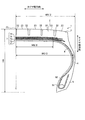
図1は、本発明の実施の形態1にかかる重荷重用空気入りタイヤを示す子午線方向の断面図、図2は、図1に示す重荷重用空気入りタイヤでの径成長を示す概略図である。
[Embodiment 1]
1 is a cross-sectional view in the meridian direction showing a heavy-duty pneumatic tire according to a first embodiment of the present invention, and FIG. 2 is a schematic diagram showing diameter growth in the heavy-duty pneumatic tire shown in FIG.
本実施の形態1にかかる重荷重用空気入りタイヤ1は、タイヤ赤道面Cを中心としてほぼ対称になるように構成されている。タイヤ赤道面Cとは、重荷重用空気入りタイヤ1の回転軸(図示せず)に直交すると共に、重荷重用空気入りタイヤ1のタイヤ幅の中心を通る平面である。また、タイヤ赤道線とは、タイヤ赤道面C上にあって空気入りタイヤ1の周方向に沿う線をいう。そして、以下に説明する重荷重用空気入りタイヤ1は、タイヤ赤道面Cを中心としてほぼ対称になるように構成されていることから、図1にはタイヤ赤道面Cを中心とした一方側のみを図示し、当該一方側のみを説明し、他方側の説明は省略する。
The heavy duty
また、以下の説明において、タイヤ周方向とは、重荷重用空気入りタイヤ1の回転軸(図示せず)を中心軸とする周り方向をいう。また、タイヤ幅方向とは、前記回転軸と平行な方向をいい、タイヤ幅方向内側とはタイヤ幅方向においてタイヤ赤道面Cに向かう側、タイヤ幅方向外側とはタイヤ幅方向においてタイヤ赤道面Cから離れる側をいう。また、タイヤ径方向とは、前記回転軸と直交する方向をいい、タイヤ径方向内側とはタイヤ径方向において回転軸に向かう側、タイヤ径方向外側とはタイヤ径方向において回転軸から離れる側をいう。
Moreover, in the following description, the tire circumferential direction refers to a circumferential direction with a rotation axis (not shown) of the heavy duty
図1に示すように、重荷重用空気入りタイヤ1は、トレッド部2と、その両側のショルダー部3と、各ショルダー部3から順次連続するサイドウォール部4およびビード部5とを含んで構成されている。さらに、重荷重用空気入りタイヤ1は、カーカス層6およびベルト層7を有する。
As shown in FIG. 1, the heavy duty
トレッド部2は、重荷重用空気入りタイヤ1の外部に露出したものであり、その表面が重荷重用空気入りタイヤ1の輪郭となる。トレッド部2の外周表面、つまり、走行時に路面と接触する踏面には、トレッド面21が形成されている。このトレッド面21には、タイヤ周方向に延在する複数の周方向溝22と、これら周方向溝22により区画形成された複数の陸部をなすリブ23とが形成されている。本実施の形態1では、トレッド部2のタイヤ幅方向の中央であってタイヤ赤道面C上となるクラウンセンターCLの位置を含み7本の周方向溝22が形成され、これら周方向溝22により8本のリブ23が形成されている。
The
ショルダー部3は、トレッド部2のタイヤ幅方向両外側の部位である。また、サイドウォール部4は、重荷重用空気入りタイヤ1におけるタイヤ幅方向の両外側に露出したものである。また、ビード部5は、ビードコア51とビードフィラ52とを有する。ビードコア51は、スチールワイヤであるビードワイヤをリング状に巻くことにより形成されている。ビードフィラ52は、カーカス層6がビードコア51の位置でタイヤ幅方向外側に折り返されることにより形成された空間に配置される。
The shoulder portion 3 is a portion on both outer sides in the tire width direction of the
カーカス層6は、ゴムで被覆された有機繊維やスチールで形成されたワイヤ層からなり、該ワイヤを空気入りタイヤ1のタイヤ赤道線に直交する態様で、空気入りタイヤ1のタイヤ周方向に沿って配置されて重荷重用空気入りタイヤ1の骨格を形成するものである。カーカス層6は、タイヤ幅方向において、トレッド部2から、その両側のショルダー部3およびサイドウォール部4を介してビード部5のビードコア51に対してトロイド状に架け渡されている。
The carcass layer 6 is formed of a wire layer formed of rubber-coated organic fibers or steel, and the wire is perpendicular to the tire equator line of the
ベルト層7は、トレッド部2においてカーカス層6よりもタイヤ径方向外側に設けられている。ベルト層7は、ゴムで被覆された有機繊維やスチールで形成されたワイヤ層からなる複数のベルトが積層されてなり、カーカス層6をタイヤ周方向に沿って覆うものである。本実施の形態1におけるベルト層7は、カーカス層6のタイヤ径方向外側からタイヤ径方向外側に向かって1番ベルト71,2番ベルト72,3番ベルト73,4番ベルト74,5番ベルトの順で積層された5層構造を有している。そして、2番ベルト72および4番ベルト74は、ゴムで被覆されるワイヤが、タイヤ周方向、つまりタイヤ赤道線に対して、10度以上30度以下の角度を有して配置されている。また、2番ベルト72および4番ベルト74は、タイヤ周方向に対して角度をなすワイヤが、積層されたベルト相互で交差して配置される交差ベルトをなしている。また、3番ベルト73は、ゴムで被覆されるワイヤが、タイヤ周方向、つまりタイヤ赤道線に対して、0度以上5度以下の角度を有して配置される、いわゆるタイヤ周方向に対して実質0度となる周方向補強層をなしている。なお、周方向補強層は、交差ベルト(2番ベルト72および4番ベルト74)間の3番ベルト73として説明しているが、交差ベルトのタイヤ径方向外側、あるいは交差ベルトのタイヤ径方向内側に配置されていてもよい。
The belt layer 7 is provided on the outer side in the tire radial direction than the carcass layer 6 in the
また、本実施の形態1にかかる重荷重用空気入りタイヤ1は、300[mm]以上のタイヤ幅方向総幅WAを有し、かつ70[%]以下の扁平率を有する重荷重用空気入りラジアルタイヤを対象としている。ここで、偏平率とは、図1に示すように、タイヤ幅方向総幅WAに対するタイヤ高さHAを比率で表したものである。タイヤ幅方向総幅WAは、重荷重用空気入りタイヤ1においてタイヤ幅方向で最も幅の広い部分であり、両端のサイドウォール部4のうちタイヤ幅方向で最も外側の部分間の距離、つまり一対のサイドウォール部4でタイヤ赤道面Cから最も離れている部分間の距離である。また、タイヤ高さHAは、ビード部のタイヤ径方向内端(リムベース位置)からクラウンセンターCLまでのタイヤ径方向に沿ったタイヤ断面高さである。なお、図1において、本実施の形態1の重荷重用空気入りタイヤ1は、タイヤ赤道面Cを中心とした一方側のみを図示してあり、タイヤ幅方向総幅WAは、その半分のWA/2として示してある。
The heavy duty
上述した重荷重用空気入りタイヤ1では、内圧100[kPa]の空気圧が付与されたときを基準とし、正規内圧の空気圧が付与された場合、トレッド部2のクラウンセンターCL、およびタイヤ幅方向最外側の周方向溝22でのタイヤ径方向への径成長(ひずみ)が0.3[%]未満となる。この径成長(ひずみ)は、0.28[%]以下が好ましく、0.25[%]以下がさらに好ましい。
In the heavy load
上記径成長(ひずみ)は、図2に示すように、上述した重荷重用空気入りタイヤ1において、内圧100[kPa]の空気圧が付与された場合(破線で示す)でのタイヤ径方向の寸法に対し、正規内圧の空気圧が付与された場合(実線で示す)でのタイヤ径方向へ成長した寸法であらわされる。具体的に、クラウンセンターCLでは、該クラウンセンターCLに位置する周方向溝22において、内圧100[kPa]の空気圧が付与された場合でのタイヤ径方向の溝底間の寸法S1に対し、正規内圧の空気圧が付与された場合でのタイヤ径方向の成長α1が、α1/S1<0.03の関係を満足する。なお、クラウンセンターCLに周方向溝22が設けられていない場合、クラウンセンターCLのトレッド面21でのタイヤ径方向への径成長(ひずみ)が0.3[%]未満を満足する。また、タイヤ幅方向最外側の周方向溝22では、タイヤ幅方向の最も外側の2つの周方向溝22において、内圧100[kPa]の空気圧が付与された場合でのタイヤ径方向の溝底間の寸法S2,S3に対し、正規内圧の空気圧が付与された場合でのタイヤ径方向の成長α2,α3が、[(α2+α3)/(S2+S3)]<0.03の関係を満足する。
As shown in FIG. 2, the radial growth (strain) is the same as the tire radial dimension in the above-described heavy-duty
なお、正規内圧とは、JATMAに規定される「最高空気圧」、TRAに規定される「TIRE LOAD LIMITS AT VARIOUS COLD INFLATION PRESSURES」の最大値、あるいはETRTOに規定される「INFLATION PRESSURES」をいう。 The normal internal pressure means “maximum air pressure” defined by JATMA, the maximum value of “TIRE LOAD LIMITS AT VARIOUS COLD INFLATION PRESSURES” defined by TRA, or “INFLATION PRESSURES” defined by ETRTO.
したがって、本実施の形態1にかかる重荷重用空気入りタイヤ1では、トレッド部2のクラウンセンターCL、およびタイヤ幅方向最外側の周方向溝22でのタイヤ径方向への径成長(ひずみ)を0.3[%]未満としたことにより、径成長のタイヤ幅方向での分布がほぼ均一となる。このため、ワイドベース偏平(扁平率70[%]以下、タイヤ幅方向総幅300[mm]以上)であっても、高内圧・高負荷荷重の長期使用条件でのベルトエッジセパレーションの発生を低減できる。この結果、耐久性および耐ワイヤ疲労性を、扁平率70[%]を上回る一般的なサイズの重荷重用空気入りタイヤと同等レベルにまで向上できる。しかも、クラウンセンターCLおよびタイヤ幅方向最外側の周方向溝22において、径成長のタイヤ幅方向での分布がほぼ均一とされたことにより、耐偏摩耗性を向上できる。
Therefore, in the heavy load
トレッド部2のクラウンセンターCL、およびタイヤ幅方向最外側の周方向溝22において、タイヤ径方向への径成長(ひずみ)が0.3[%]未満を満足する具体的な構成は、ベルト層7において、タイヤ周方向に10度以上30度以下の角度を有して配置された交差ベルト(2番ベルト72および4番ベルト74)と、タイヤ周方向に0度以上5度以下の角度を有して配置された周方向補強層(3番ベルト73)を備えたことである。なお、タイヤ径方向への径成長(ひずみ)が0.3[%]未満を満足するには、タイヤ周方向に10度以上30度以下の角度を有して配置された交差ベルト(72,74)が少なくとも2つ設けられていればよく、かつ、タイヤ周方向に0度以上5度以下の角度を有して配置された周方向補強層(73)が少なくとも1つ設けられていればよい。また、周方向補強層(73)は、少なくとも2つ設けられている交差ベルト(72,74)の間に挟まれる形態で設けられていることがさらに好ましい。
In the crown center CL of the
このベルト層7によれば、カーカス層6に締め付け力を与えての剛性を高めることにより、トレッド部2のクラウンセンターCL、およびタイヤ幅方向最外側の周方向溝22でのタイヤ径方向への径成長(ひずみ)を0.3[%]未満にすることができる。
According to this belt layer 7, by increasing the rigidity by applying a tightening force to the carcass layer 6, the crown center CL of the
また、本実施の形態1にかかる重荷重用空気入りタイヤ1では、トレッド部2のクラウンセンターCL、およびタイヤ幅方向最外側の周方向溝22において、タイヤ径方向への径成長(ひずみ)を0.3[%]未満とするにあたり、正規荷重W[kN]に対し、交差ベルト(72,74)および周方向補強層(73)の周方向強力の総和ΣL[kN]が、3.00≦ΣL/W≦4.20の範囲に設定されていることが好ましい。
In the heavy load
すなわち、ベルト層7の周方向強力を向上することで、タイヤ径方向への径成長(ひずみ)を0.3[%]未満にできる。周方向強力は、タイヤ周方向のワイヤの強力であり、(ワイヤ破断強力)×(ワイヤエンド本数(本/50[mm]))×(cos[ワイヤ角度]2)であらわされる。したがって、ベルト層7の周方向強力を向上するには、ワイヤ破断強力を向上し、ワイヤエンド本数を増加し、タイヤ周方向に対するワイヤ角度を小さくすればよい。ワイヤ破断強力は、例えば、交差ベルト(72,74)および/または周方向補強層(73)のワイヤの径を太くしたり、あるいは破断強力の高いワイヤの材質を使用したり、もしくは有機繊維ワイヤの含有炭素量を増すことにより向上する。また、ワイヤエンド本数は、交差ベルト(72,74)および周方向補強層(73)の50[mm]当たりのワイヤ本数を増加すればよい。また、ワイヤ角度は、交差ベルト(72,74)および周方向補強層(73)のタイヤ周方向に対するワイヤの角度を小さくすればよい。このように、ワイヤ破断強力、ワイヤエンド本数もしくはワイヤ角度を調整することにより、3.00≦ΣL/W≦4.20の範囲が得られる。ΣL/Wが3.00を下回ると耐久性が低下し、ΣL/Wが4.20を上回るとタイヤ重量が増すと共に、製造コストが増大する。 That is, by improving the circumferential strength of the belt layer 7, the radial growth (strain) in the tire radial direction can be made less than 0.3%. The circumferential strength is the strength of the wire in the tire circumferential direction, and is represented by (wire breaking strength) × (number of wire ends (lines / 50 [mm])) × (cos [wire angle] 2 ). Therefore, in order to improve the circumferential strength of the belt layer 7, it is only necessary to improve the wire breaking strength, increase the number of wire ends, and reduce the wire angle with respect to the tire circumferential direction. For example, the wire breaking strength may be increased by increasing the wire diameter of the cross belt (72, 74) and / or the circumferential reinforcing layer (73), using a wire material having a high breaking strength, or by using an organic fiber wire. It improves by increasing the carbon content. Further, the number of wire ends may be increased by increasing the number of wires per 50 [mm] of the cross belts (72, 74) and the circumferential reinforcing layer (73). Moreover, what is necessary is just to make a wire angle small with respect to the tire circumferential direction of a crossing belt (72, 74) and a circumferential direction reinforcement layer (73). Thus, the range of 3.00 ≦ Σ L / W ≦ 4.20 is obtained by adjusting the wire breaking strength, the number of wire ends, or the wire angle. When Σ L / W is less than 3.00, the durability is lowered. When Σ L / W is more than 4.20, the tire weight is increased and the manufacturing cost is increased.
さらに、3.00≦ΣL/W≦4.20の範囲を満足する場合、正規荷重W[kN]に対し、交差ベルト(72,74)の周方向強力の総和ΣM[kN]が、1.80≦ΣM/W≦2.60の範囲に設定されていることが、ベルト層7全体での周方向強力を向上するうえでより好ましい。 Further, when the range of 3.00 ≦ Σ L / W ≦ 4.20 is satisfied, the sum Σ M [ kN] of the circumferential strength of the cross belts (72, 74) with respect to the normal load W [kN] It is more preferable to set the range of 1.80 ≦ ΣM / W ≦ 2.60 in order to improve the circumferential strength of the entire belt layer 7.
なお、正規荷重とは、JATMAに規定される「最大負荷能力(最大荷重)」、TRAに規定される「TIRE LOAD LIMITS AT VARIOUS COLD INFLATION PRESSURES」の最大値、あるいはETRTOに規定される「LOAD CAPACITY」をいう。 The normal load is the maximum load capacity (maximum load) specified by JATMA, the maximum value of “TIRE LOAD LIMITS AT VARIOUS COLD INFLATION PRESSURES” specified by TRA, or “LOAD CAPACITY” specified by ETRTO. ".
また、本実施の形態1にかかる重荷重用空気入りタイヤ1では、正規内圧P[kPa]に対し、交差ベルト(72,74)および周方向補強層(73)の周方向強力の総和ΣL[kN]が、0.20≦ΣL/P≦0.25の範囲に設定されていることが好ましい。ΣL/Pが0.20を下回ると耐久性が低下し、ΣL/Pが0.25を上回るとタイヤ重量が増すと共に、製造コストが増大する。
In the heavy-duty
さらに、0.20≦ΣL/P≦0.25の範囲を満足する場合、正規内圧P[kPa]に対し、交差ベルト(72,74)の周方向強力の総和ΣM[kN]が、0.12≦ΣM/P≦0.16の範囲に設定されていることが、ベルト層7全体での周方向強力を向上するうえでより好ましい。 Furthermore, when the range of 0.20 ≦ Σ L / P ≦ 0.25 is satisfied, the sum Σ M [ kN] of the circumferential strength of the cross belts (72, 74) with respect to the normal internal pressure P [kPa] In order to improve the circumferential strength of the entire belt layer 7, it is more preferable that the range is set to 0.12 ≦ Σ M / P ≦ 0.16.
また、本実施の形態1にかかる重荷重用空気入りタイヤ1では、正規内圧の空気圧を付与した場合のタイヤ子午線方向の断面視で、図1に示すように、カーカス層6のタイヤ幅方向最大幅WCに対し、周方向補強層(73)のタイヤ幅方向最大幅WBが、0.60≦WB/WC≦0.75の範囲に設定されていることが好ましい。このように構成することにより、クラウンセンターCLからタイヤ幅方向最外側の周方向溝22までのタイヤ径方向への径成長(ひずみ)を0.3[%]未満で均一化させることができ、耐偏摩耗性をさらに向上できる。
Further, in the heavy duty
周方向補強層(73)のタイヤ幅方向最大幅WBは、周方向補強層(73)のタイヤ幅方向での両端間の距離である。また、カーカス層6のタイヤ幅方向最大幅WCは、カーカス層6においてタイヤ幅方向で最も幅の広い部分であり、両端のサイドウォール部4の位置にあってタイヤ幅方向で最も外側の部分間の距離、つまりタイヤ赤道面Cから最も離れている部分間の距離である。なお、図1において、本実施の形態1の重荷重用空気入りタイヤ1は、タイヤ赤道面Cを中心とした一方側のみを図示してあり、周方向補強層(73)のタイヤ幅方向最大幅WBは、その半分のWB/2として示してあり、カーカス層6のタイヤ幅方向最大幅WCは、その半分のWC/2として示してある。
The maximum width WB in the tire width direction of the circumferential reinforcing layer (73) is a distance between both ends of the circumferential reinforcing layer (73) in the tire width direction. The maximum width WC in the tire width direction of the carcass layer 6 is the widest portion in the tire width direction in the carcass layer 6, and is located between the outermost portions in the tire width direction at the positions of the sidewall portions 4 at both ends. , That is, the distance between the parts farthest from the tire equatorial plane C. In FIG. 1, the heavy-duty
[実施の形態2]
上述した実施の形態1にかかる重荷重用空気入りタイヤ1において、耐久性、耐ワイヤ疲労性および耐偏摩耗性を向上するため、以下のように構成することが好ましい。
[Embodiment 2]
The heavy load
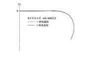
図3は、本発明の実施の形態2にかかる重荷重用空気入りタイヤを示す子午線方向の断面図、図4は、本発明の実施の形態2にかかる重荷重用空気入りタイヤの各扁平率による相異を示すグラフ、図5は、本発明の実施の形態2にかかる重荷重用空気入りタイヤのカーカスラインを示す説明図、図6は、本発明の実施の形態2にかかる重荷重用空気入りタイヤの作用を示す説明図である。なお、以下に説明する実施の形態2において、上述した実施の形態1と同等部分には同一の符号を付し、その説明を省略する。 FIG. 3 is a cross-sectional view in the meridian direction showing the heavy-duty pneumatic tire according to the second embodiment of the present invention, and FIG. 4 shows phases according to the respective flatness ratios of the heavy-duty pneumatic tire according to the second embodiment of the present invention. FIG. 5 is an explanatory diagram showing a carcass line of the heavy duty pneumatic tire according to the second embodiment of the present invention, and FIG. 6 is a diagram of the heavy duty pneumatic tire according to the second embodiment of the present invention. It is explanatory drawing which shows an effect | action. In the second embodiment described below, the same parts as those in the first embodiment are denoted by the same reference numerals, and the description thereof is omitted.
本実施の形態2にかかる重荷重用空気入りタイヤ1では、タイヤが加硫成形金型内に保持されているときのタイヤ子午線方向の断面視を基準として、各タイヤ寸法が規定される。これに限らず、例えば、タイヤベース幅が適用リムのリム幅の100[%]以上120[%]以下の幅となるように、タイヤが単体で保持されたタイヤ単体時におけるタイヤ子午線方向の断面視を基準として、各タイヤ寸法が規定されても良い。なお、タイヤ単体の形状とは、適用リム8にリム組みされる前のタイヤ単体の形状をいう。このときのタイヤ単体の形状は、加硫成形金型内におけるタイヤ形状(タイヤが加硫成形金型から取り出される直前のタイヤ形状)にほぼ等しい。また、一般に、タイヤの設計寸法は、かかるインモールド時のタイヤ形状を基準として規定される。言い換えると、加硫成形金型内におけるタイヤ形状とは、適用リム8にリム組みされる前のタイヤ単体の形状にほぼ等しい。
In the heavy duty
図3に示すように、タイヤ子午線方向の断面視にて、適用リム(ホイールのリムフランジ部)8の仮想線を引き、リム高さFHの位置(リムフランジ部のタイヤ径方向の最外点A)からタイヤ幅方向に引いた直線をX軸とする。また、タイヤのクラウンセンターCLを通りタイヤ径方向に引いた直線をY軸(タイヤ中心軸)とする。 As shown in FIG. 3, in a sectional view in the tire meridian direction, an imaginary line of the applicable rim (wheel rim flange portion) 8 is drawn, and the position of the rim height FH (the outermost point in the tire radial direction of the rim flange portion) A straight line drawn from A) in the tire width direction is taken as the X axis. A straight line passing through the crown center CL of the tire and drawn in the tire radial direction is defined as a Y axis (tire central axis).
次に、タイヤベース幅の半分の幅WDと、Y軸からカーカス層6のタイヤ幅方向最大幅位置Tまでの距離WEと、Y軸からカーカス層6の変曲点Qまでの距離WFとをとる。また、リム高さFHの位置AからクラウンセンターCLにおけるカーカス層6の頂点Rまでの距離HBをとる。 Next, a width WD that is half the tire base width, a distance WE from the Y axis to the maximum width position T in the tire width direction of the carcass layer 6, and a distance WF from the Y axis to the inflection point Q of the carcass layer 6 Take. Further, the distance HB from the position A of the rim height FH to the vertex R of the carcass layer 6 at the crown center CL is taken.
なお、適用リムとは、JATMAに規定される「適用リム」、TRAに規定される「Design Rim」、あるいはETRTOに規定される「Measuring Rim」をいう。また、リム高さFHは、ホイールのリム径φを基準としたリムフランジ部の高さにより規定される。 The applied rim refers to “applied rim” defined in JATMA, “Design Rim” defined in TRA, or “Measuring Rim” defined in ETRTO. Also, the rim height FH is defined by the height of the rim flange portion with reference to the wheel rim diameter φ.
また、カーカス層6の変曲点Qは、タイヤ子午線方向の断面視にてクラウンセンターCLからタイヤ幅方向外側に向かってカーカス層6の曲率半径の変化をみたときに、カーカス層6がタイヤ径方向内側に曲がり始める位置により定義される。具体的には、ベルト層7よりもタイヤ幅方向外側の位置におけるカーカス層6の曲率半径RAと、この位置よりもタイヤ幅方向内側(クラウンセンターCL側)の位置におけるカーカス層6の曲率半径RBとが1[%]≦RA/RB≦10[%]の関係を有する範囲内に、カーカス層6の変曲点Qが位置する。また、変曲点Qは、トレッド部センター領域のカーカスラインを近似して成る円弧が、このカーカスラインから剥離する点として定義されても良い。 The inflection point Q of the carcass layer 6 is such that the carcass layer 6 has a tire diameter when a change in the radius of curvature of the carcass layer 6 is seen from the crown center CL toward the outer side in the tire width direction in a cross-sectional view in the tire meridian direction. It is defined by the position where it starts to bend in the direction. Specifically, the radius of curvature RA of the carcass layer 6 at a position outside the belt layer 7 in the tire width direction and the radius of curvature RB of the carcass layer 6 at a position inside the tire width direction (crown center CL side) from this position. And the inflection point Q of the carcass layer 6 is located within a range in which 1 and 2 have a relationship of 1 [%] ≦ RA / RB ≦ 10 [%]. Further, the inflection point Q may be defined as a point where an arc formed by approximating the carcass line in the center area of the tread portion peels from the carcass line.
本実施の形態2の重荷重用空気入りタイヤ1では、タイヤ子午線方向の断面視におけるカーカス層6の断面形状(カーカスライン)にて、所定の寸法比USH/HB、WE/HB、WF/WEが所定の二次式近似により規定されている点に特徴を有する。
In the heavy duty
具体的には、図3に示すように、まず、カーカス層6のタイヤ幅方向最大幅位置Tからカーカス層6の変曲点QまでのY軸方向の距離USHと、X軸からクラウンセンターCLにおけるカーカス層6の頂点Rまでの距離HBとが0.48≦USH/HB≦0.52の関係を有する。また、タイヤの扁平率の呼びSと、Y軸からカーカス層6のタイヤ幅方向最大幅位置Tまでの距離WEと、距離HBとが5.52S2×10−5−2.407S×10−2+2.29≦WE/HB≦5.52S2×10−5−2.407S×10−2+2.39の関係を有する。また、扁平率の呼びSと、Y軸から前記カーカス層の変曲点Qまでの距離WFと、距離WEとが−1.1312S2×10−4+5.822S×10−3+0.62≦WF/WE≦−1.1312S2×10−4+5.822S×10−3+0.68の関係を有する。 Specifically, as shown in FIG. 3, first, the distance USH in the Y-axis direction from the maximum width position T of the carcass layer 6 in the tire width direction to the inflection point Q of the carcass layer 6, and the X-axis to the crown center CL. And the distance HB to the vertex R of the carcass layer 6 has a relationship of 0.48 ≦ USH / HB ≦ 0.52. Further, the nominal flatness S of the tire, the distance WE from the Y-axis to the maximum width position T in the tire width direction of the carcass layer 6, and the distance HB are 5.52S 2 × 10 −5 −2.407S × 10 −. 2 + 2.29 ≦ WE / HB ≦ 5.52S 2 × 10 −5 −2.407S × 10 −2 +2.39 Further, the nominal length S, the distance WF from the Y axis to the inflection point Q of the carcass layer, and the distance WE are −1.112 S 2 × 10 −4 +5.822 S × 10 −3 + 0.62 ≦ WF / WE ≦ −1.11212S 2 × 10 −4 + 5.822S × 10 −3 +0.68
この重荷重用空気入りタイヤ1では、カーカス層6の断面形状(カーカスライン)が適正化されているので、タイヤの単体時とインフレート時とにおける周方向溝22(特に、タイヤ幅方向外側に位置する周方向溝22)の形状変化が低減される。したがって、タイヤがリム組みされてタイヤに空気圧が付与されたときに、周方向溝22の溝底が広がり難い。これにより、周方向溝22の溝底に発生するひずみが低減されてグルーブクラックの発生が抑制される利点がある。
In this heavy-duty
また、WE/HBおよびWF/WEが所定の二次式近似により規定されるので、これらが一次式近似により規定される構成と比較して、カーカス層6の断面形状が高精度に適正化される(図5参照)。具体的には、二次式近似の方が一次式近似よりも周方向溝22の溝底部付近におけるカーカスラインの位置が高くなる(タイヤ径方向に位置する)。すると、タイヤの単体時とインフレート時とにおける周方向溝22の形状変化が効果的に低減されて、周方向溝22の溝底に発生するひずみが低減される。これにより、タイヤの耐グルーブクラック性能が向上する。
Further, since WE / HB and WF / WE are defined by a predetermined quadratic approximation, the cross-sectional shape of the carcass layer 6 is optimized with high accuracy compared to the configuration defined by the linear approximation. (See FIG. 5). Specifically, the position of the carcass line in the vicinity of the groove bottom of the
なお、一般には、比USH/HB、比WE/HBおよび比WF/WEと、タイヤの耐グルーブクラック性能およびベルト層7の耐久性能が以下の関係を有する(図6参照)。まず、比USH/HBが増加(大)すると、耐グルーブクラック性能が向上してベルト層7の耐久性能が低下する傾向にある。逆に、比USH/HBが減少(小)すると、耐グルーブクラック性能が低下してベルト層7の耐久性能が向上する傾向にある。また、比WE/HBが増加(大)すると、耐グルーブクラック性能が低下してベルト層7の耐久性能が向上する傾向にある。逆に、比WE/HBが減少(小)すると、耐グルーブクラック性能が向上してベルト層7の耐久性能が低下する傾向にある。また、比WF/WEが増加(大)すると、耐グルーブクラック性能が低下してベルト層7の耐久性能が向上する傾向にある。逆に、比WF/WEが減少(小)すると、耐グルーブクラック性能が向上してベルト層7の耐久性能が低下する傾向にある。 In general, the ratio USH / HB, the ratio WE / HB, and the ratio WF / WE, the groove crack resistance of the tire, and the durability of the belt layer 7 have the following relationship (see FIG. 6). First, when the ratio USH / HB increases (large), the groove crack resistance tends to improve and the durability of the belt layer 7 tends to decrease. On the contrary, when the ratio USH / HB decreases (small), the groove crack resistance tends to be lowered and the durability of the belt layer 7 tends to be improved. Further, when the ratio WE / HB increases (large), the groove crack resistance tends to decrease and the durability of the belt layer 7 tends to improve. On the contrary, when the ratio WE / HB decreases (small), the groove crack resistance is improved and the durability of the belt layer 7 tends to be lowered. Further, when the ratio WF / WE increases (large), the groove crack resistance tends to decrease and the durability of the belt layer 7 tends to improve. Conversely, when the ratio WF / WE decreases (small), the groove crack resistance tends to improve and the durability of the belt layer 7 tends to decrease.
また、この重荷重用空気入りタイヤ1では、タイヤベース幅の半分の幅WDとタイヤ断面幅の呼びMとが0.44≦WD/M≦0.46の関係を有することが好ましい。かかる構成では、タイヤベース幅(半幅WD)とタイヤ断面幅の呼びMとの比WD/Mが適正化されるので、タイヤのエアインフレート性能、ビード部の耐久性能および耐製造故障性能が向上する利点がある。なお、理論リム幅は、この比WD/Mが、WD/M=0.75となり、使用リム幅には、この数値に近いものが採用される。したがって、WD/Mが上記の範囲(0.44≦WD/M≦0.46)に設定される構成では、タイヤのベース幅が広くなる。なお、タイヤ断面幅とは、タイヤ幅方向総幅WAからタイヤの側面の模様・文字等を除いた幅である。
In the heavy-duty
また、この重荷重用空気入りタイヤ1では、ベルト層7よりもタイヤ幅方向外側の位置におけるカーカス層6の曲率半径RAと、カーカス層6のタイヤ幅方向最大幅位置Tからカーカス層6の変曲点QまでのY軸方向の距離USHとが0.95≦RA/USH≦1.05の関係を有することが好ましい(図3参照)。かかる構成では、ショルダー部3からサイドウォール部4に至るカーカスラインの曲率半径RAが適正化されるので、周方向溝22の溝底に発生するひずみが効果的に低減されてグルーブクラックの発生が抑制される利点がある。例えば、RA/USH<0.95では、インフレート時におけるカーカスラインがタイヤ単体時よりもタイヤ幅方向外側に変形し易くなり好ましくない。また、1.05<RA/USHでは、タイヤ形状自体が不適正となり、タイヤ重量の増加やタイヤ耐久性能の低下などの不具合が生じ易い。
In the heavy-duty
また、この重荷重用空気入りタイヤ1では、タイヤが適用リムにリム組みされると共にタイヤに正規内圧の5[%]の空気圧が付与された状態にて、タイヤの扁平率の呼びSと、距離USHと、距離HBと、距離WEと、距離WFとが、4.157S2×10−5−6.738S×10−3+0.56≦USH/HB≦4.157S2×10−5−6.738S×10−3+0.63の関係を有し、かつ、1.7874S2×10−4−2.7522S×10−2+1.60≦WF/WE≦1.7874S2×10−4−2.7522S×10−2+1.66の関係を有することが好ましい。
In the heavy-duty
かかる構成では、カーカス層の形状がさらに適正化されるので、インフレート時における主溝の形状変化が低減される。これにより、主溝の溝底に発生するひずみが低減されてグルーブクラックの発生がより効果的に抑制される利点がある。 In such a configuration, since the shape of the carcass layer is further optimized, a change in the shape of the main groove during inflation is reduced. Thereby, there exists an advantage by which the distortion which generate | occur | produces in the groove bottom of a main groove is reduced and generation | occurrence | production of a groove crack is suppressed more effectively.
例えば、扁平率の呼びSがS=60であるタイヤでは、0.305≦USH/HB≦0.375、かつ、0.592≦WF/WE≦0.652となる。また、タイヤサイズ265/60R22.5のタイヤのプロファイルでは、USH/HB=0.29、かつ、WF/WE=0.67となる。 For example, in a tire having a flatness nominal S S = 60, 0.305 ≦ USH / HB ≦ 0.375 and 0.592 ≦ WF / WE ≦ 0.652. In the tire profile of the tire size 265 / 60R22.5, USH / HB = 0.29 and WF / WE = 0.67.
なお、この重荷重用空気入りタイヤ1は、例えば、扁平率の呼びSがS≦70の範囲にあるタイヤに適用されることが好ましい。この重荷重用空気入りタイヤ1では、特にグルーブクラックの発生が顕著である。したがって、これらのタイヤを適用対象とすることにより、より顕著な耐グルーブクラック性能に関する効果が得られる利点がある。
The heavy load
[性能試験]
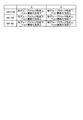
図7は、本発明の実施の形態にかかる重荷重用空気入りタイヤの性能試験の結果を示す図表である。図7に示すように、上述した実施の形態1,2では、条件が異なる複数種類の重荷重用空気入りタイヤについて、耐久性、耐ワイヤ疲労性、および耐偏摩耗性に関する性能試験が行われた。この性能試験では、タイヤサイズ445/50R22.5の重荷重用空気入りタイヤが用いられる。そして、この重荷重用空気入りタイヤが22.5×14.00のリムに装着され、この重荷重用空気入りタイヤに正規内圧(最高空気圧)が付与され、かつ正規荷重(最大荷重)が負荷される。
[performance test]
FIG. 7 is a chart showing results of performance tests of the heavy duty pneumatic tire according to the embodiment of the present invention. As shown in FIG. 7, in the first and second embodiments described above, performance tests relating to durability, wire fatigue resistance, and uneven wear resistance were performed on a plurality of types of heavy-duty pneumatic tires having different conditions. . In this performance test, a heavy duty pneumatic tire having a tire size of 445 / 50R22.5 is used. The heavy load pneumatic tire is mounted on a 22.5 × 14.00 rim, and a normal internal pressure (maximum air pressure) is applied to the heavy load pneumatic tire, and a normal load (maximum load) is applied. .
耐久性に関する性能試験では、上記重荷重用空気入りタイヤにてドラム試験が行われ、時速45[km/h]の走行速度にてタイヤが破壊するまでの走行距離が測定される。そして、この測定結果に基づいて従来例を基準(100)とした指数評価が行われる。この評価は、走行距離が長いほど数値が大きく好ましい。 In the performance test regarding durability, a drum test is performed on the heavy-duty pneumatic tire, and a travel distance until the tire breaks at a travel speed of 45 [km / h] is measured. Then, based on this measurement result, index evaluation using the conventional example as a reference (100) is performed. In this evaluation, the longer the travel distance, the larger the numerical value and the better.
耐ワイヤ疲労性に関する性能試験では、上記重荷重用空気入りタイヤを3軸トレーラに装着し、10万[km]走行させた。そして、タイヤ新品時と走行後の周方向補強層のワイヤ破断強力により強力保持率が算出される。この算出結果に基づいて従来例を基準(100)とした指数評価が行われる。この評価は、強力保持率が高いほど数値が大きく好ましい。 In the performance test related to wire fatigue resistance, the heavy duty pneumatic tire was mounted on a triaxial trailer and traveled 100,000 km. And the strength retention is calculated by the wire breaking strength of the circumferential reinforcing layer when the tire is new and after running. Based on this calculation result, index evaluation is performed using the conventional example as a reference (100). In this evaluation, the higher the strength retention rate, the larger the numerical value.
耐偏摩耗性に関する性能試験では、上記重荷重用空気入りタイヤを3軸トレーラに装着し、10万[km]走行させた。そして、クラウンセンターの周方向溝の溝摩耗量と、タイヤ幅方向最外側の周方向溝の溝摩耗量との比率が算出される。この算出結果に基づいて従来例を基準(100)とした指数評価が行われる。この評価は、溝摩耗量の比率が低いほど数値が大きく好ましい。 In the performance test regarding uneven wear resistance, the heavy-duty pneumatic tire was mounted on a triaxial trailer and allowed to travel 100,000 [km]. Then, the ratio between the groove wear amount of the circumferential groove of the crown center and the groove wear amount of the circumferential groove on the outermost side in the tire width direction is calculated. Based on this calculation result, index evaluation is performed using the conventional example as a reference (100). In this evaluation, the lower the ratio of the groove wear amount, the larger the numerical value.
従来例の重荷重用空気入りタイヤは、市販されている既存のタイヤである。発明例1〜発明例3の重荷重用空気入りタイヤ1は、各寸法(幅WD、距離WE、距離WF、距離HB)および、カーカスライン(USH/HB、WE/HB、WF/WE、WD/M)が適正化されているタイヤである。この試験結果に示すように、発明例1〜3の重荷重用空気入りタイヤ1では、いずれも耐久性、耐ワイヤ疲労性、および耐偏摩耗性が向上していることが分かる。
The conventional heavy-duty pneumatic tire is an existing tire that is commercially available. The heavy duty
以上のように、本発明にかかる重荷重用空気入りタイヤは、耐久性、耐ワイヤ疲労性、および耐偏摩耗性を向上することに適している。 As described above, the heavy duty pneumatic tire according to the present invention is suitable for improving durability, wire fatigue resistance, and uneven wear resistance.
1 重荷重用空気入りタイヤ
2 トレッド部
21 トレッド面
22 周方向溝
23 リブ
3 ショルダー部
4 サイドウォール部
5 ビード部
51 ビードコア
52 ビードフィラ
6 カーカス層
7(71,72,73,74,75) ベルト層
72,74 交差ベルト
73 周方向補強層
8 リム
C タイヤ赤道面
CL クラウンセンター
W 正規荷重
P 正規内圧
A リムフランジ部のタイヤ径方向の最外点
HA タイヤ高さ
HB X軸からクラウンセンターにおけるカーカス層の頂点までの距離
T カーカス層のタイヤ幅方向最大幅位置
Q カーカス層の変曲点
R カーカス層の頂点
RA ベルト層よりもタイヤ幅方向外側の位置におけるカーカス層の曲率半径
RB クラウンセンター側の位置におけるカーカス層の曲率半径
WA タイヤ幅方向総幅
WB 周方向補強層のタイヤ幅方向最大幅
WC カーカス層のタイヤ幅方向最大幅
WD タイヤベース幅の半幅
WE Y軸からカーカス層のタイヤ幅方向最大幅位置までの距離
WF Y軸からカーカス層の変曲点までの距離
USH タイヤ幅方向最大幅位置からカーカス層の変曲点までのY軸方向の距離
φ リム径
ΣL 交差ベルトおよび周方向補強層の周方向強力の総和
ΣM 交差ベルトの周方向強力の総和
S1,S2,S3 内圧100[kPa]の空気圧が付与された場合でのタイヤ径方向の溝底間の寸法
α1,α2,α3 正規内圧の空気圧が付与された場合でのタイヤ径方向の成長
1 Heavy load pneumatic tire 2 Tread portion 21 Tread surface 22 Circumferential groove 23 Rib 3 Shoulder portion 4 Side wall portion 5 Bead portion 51 Bead core 52 Bead filler 6 Carcass layer 7 (71, 72, 73, 74, 75) Belt layer 72 , 74 Cross belt 73 Circumferential reinforcement layer 8 Rim C Tire equatorial plane CL Crown center W Regular load P Normal internal pressure A Outermost point in the tire radial direction of the rim flange HA Tire height HB From the X axis to the carcass layer at the crown center Distance to the apex T Maximum position in the tire width direction of the carcass layer Q Inflection point of the carcass layer R Apex of the carcass layer RA Radius of curvature of the carcass layer at a position outside the belt width RB In the position on the crown center side Curvature radius of carcass layer WA Total width in tire width WB Maximum width in the tire width direction of the direction reinforcing layer WC Maximum width in the tire width direction of the carcass layer WD Half width of the tire base width WE Distance from the Y axis to the maximum width position in the tire width direction of the carcass layer WF Inflection point of the carcass layer from the Y axis Distance to USH Distance in the Y-axis direction from the maximum width position in the tire width direction to the inflection point of the carcass layer φ Rim diameter Σ Sum of circumferential strengths of the L cross belt and circumferential reinforcing layer Σ Circumferential strength of the M cross belt S1, S2, S3 Dimensions between groove bottoms in the tire radial direction when an air pressure with an internal pressure of 100 [kPa] is applied α1, α2, α3 Tire diameter direction when an air pressure with a normal internal pressure is applied growth
Claims (10)
加硫成形金型内にて保持されているときのタイヤ子午線方向の断面視にて、リム高さFHの位置Aからタイヤ幅方向に引いた直線をX軸とすると共に、クラウンセンターCLを通りタイヤ径方向に引いた直線をY軸とするとき、
扁平率の呼びSと、前記カーカス層のタイヤ幅方向最大幅位置Tから前記カーカス層の変曲点QまでのY軸方向の距離USHと、X軸からクラウンセンターCLにおける前記カーカス層の頂点Rまでの距離HBと、Y軸から前記カーカス層のタイヤ幅方向最大幅位置Tまでの距離WEと、Y軸から前記カーカス層の変曲点Qまでの距離WFとが、0.48≦USH/HB≦0.52、5.52S 2 ×10 −5 −2.407S×10 −2 +2.29≦WE/HB≦5.52S 2 ×10 −5 −2.407S×10 −2 +2.39、および、−1.1312S 2 ×10 −4 +5.822S×10 −3 +0.62≦WF/WE≦−1.1312S 2 ×10 −4 +5.822S×10 −3 +0.68の関係を有し、
正規荷重W[kN]に対し、前記交差ベルトおよび前記周方向補強層の周方向強力の総和ΣL[kN]が、3.00≦ΣL/W≦4.20の範囲に設定されていることを特徴とする重荷重用空気入りタイヤ。 When the tread portion has a circumferential groove extending in the tire circumferential direction on the tread surface, and when an air pressure of an internal pressure of 100 [kPa] is applied as a reference, the crown of the tread portion is applied. The radial growth in the tire radial direction at the center and the circumferential groove on the outermost side in the tire width direction is less than 0.3 [%], and the outer side in the tire radial direction of the carcass layer is 10 in the tire circumferential direction. two and cross belt to such a 30-degree angle of less than or more degrees, provided in the tire radial direction inner side in the tire radial direction outer side or the cross belt or between the cross belt of the crossing belt 0 with respect to the tire circumferential direction in heavy duty pneumatic tire having a a a to one circumferential reinforcement layer 5 degrees or less angle or more degrees,
In a cross-sectional view in the tire meridian direction when held in the vulcanization mold, the straight line drawn from the position A of the rim height FH in the tire width direction is taken as the X axis and passes through the crown center CL. When the straight line drawn in the tire radial direction is the Y axis,
The nominal length S, the distance USH in the Y-axis direction from the maximum width position T of the carcass layer in the tire width direction to the inflection point Q of the carcass layer, and the vertex R of the carcass layer at the crown center CL from the X-axis The distance HB from the Y axis to the maximum width position T in the tire width direction of the carcass layer, and the distance WF from the Y axis to the inflection point Q of the carcass layer are 0.48 ≦ USH / HB ≦ 0.52, 5.52S 2 × 10 −5 −2.407S × 10 −2 + 2.29 ≦ WE / HB ≦ 5.52S 2 × 10 −5 −2.407S × 10 −2 +2.39, And -1.1312S 2 × 10 −4 + 5.822S × 10 −3 + 0.62 ≦ WF / WE ≦ −1.112S 2 × 10 −4 + 5.822S × 10 −3 +0.68 ,
That the sum ΣL [kN] of the circumferential strength of the cross belt and the circumferential reinforcing layer is set in a range of 3.00 ≦ ΣL / W ≦ 4.20 with respect to the normal load W [kN]. Features heavy duty pneumatic tires.
Priority Applications (4)
| Application Number | Priority Date | Filing Date | Title |
|---|---|---|---|
| JP2008061630A JP4670880B2 (en) | 2008-03-11 | 2008-03-11 | Heavy duty pneumatic tire |
| US12/397,975 US8225834B2 (en) | 2008-03-11 | 2009-03-04 | Pneumatic tire for heavy load |
| EP09003387.9A EP2103453B1 (en) | 2008-03-11 | 2009-03-09 | Pneumatic tire for heavy load |
| CN2009101264720A CN101531121B (en) | 2008-03-11 | 2009-03-11 | Pneumatic tire for heavy load |
Applications Claiming Priority (1)
| Application Number | Priority Date | Filing Date | Title |
|---|---|---|---|
| JP2008061630A JP4670880B2 (en) | 2008-03-11 | 2008-03-11 | Heavy duty pneumatic tire |
Publications (3)
| Publication Number | Publication Date |
|---|---|
| JP2009214760A JP2009214760A (en) | 2009-09-24 |
| JP2009214760A5 JP2009214760A5 (en) | 2009-11-12 |
| JP4670880B2 true JP4670880B2 (en) | 2011-04-13 |
Family
ID=40886106
Family Applications (1)
| Application Number | Title | Priority Date | Filing Date |
|---|---|---|---|
| JP2008061630A Active JP4670880B2 (en) | 2008-03-11 | 2008-03-11 | Heavy duty pneumatic tire |
Country Status (4)
| Country | Link |
|---|---|
| US (1) | US8225834B2 (en) |
| EP (1) | EP2103453B1 (en) |
| JP (1) | JP4670880B2 (en) |
| CN (1) | CN101531121B (en) |
Families Citing this family (28)
| Publication number | Priority date | Publication date | Assignee | Title |
|---|---|---|---|---|
| US20110265926A1 (en) * | 2010-04-28 | 2011-11-03 | Societe De Technologie Michelin | Tire tread for preventing irregular wear |
| JP5683977B2 (en) * | 2011-01-25 | 2015-03-11 | 株式会社ブリヂストン | Agricultural tires |
| EP2799259B1 (en) * | 2012-01-26 | 2017-06-14 | Sumitomo Rubber Industries, Ltd. | Pneumatic tire |
| FR2986741B1 (en) * | 2012-02-10 | 2014-03-07 | Michelin & Cie | PNEUMATIC REINFORCED ALLEGE. |
| JP5520334B2 (en) * | 2012-04-04 | 2014-06-11 | 住友ゴム工業株式会社 | Pneumatic tire |
| CN104349911B (en) * | 2012-07-13 | 2016-07-06 | 横滨橡胶株式会社 | Pneumatic tire |
| US9259971B2 (en) | 2012-07-13 | 2016-02-16 | The Yokohama Rubber Co., Ltd. | Pneumatic tire |
| WO2014010091A1 (en) | 2012-07-13 | 2014-01-16 | 横浜ゴム株式会社 | Pneumatic tire |
| JP5974897B2 (en) * | 2012-10-10 | 2016-08-23 | 横浜ゴム株式会社 | Pneumatic tire |
| KR101730943B1 (en) * | 2012-10-10 | 2017-05-11 | 요코하마 고무 가부시키가이샤 | Pneumatic tire |
| KR101710070B1 (en) * | 2012-10-10 | 2017-03-08 | 요코하마 고무 가부시키가이샤 | Pneumatic tire |
| FR2999985B1 (en) * | 2012-12-20 | 2017-02-03 | Michelin & Cie | PNEUMATIC TOP FOR A HEAVY VEHICLE OF GENIE CIVIL TYPE |
| FR2999984B1 (en) * | 2012-12-20 | 2016-02-12 | Michelin & Cie | PNEUMATIC TOP FOR A HEAVY VEHICLE OF GENIE CIVIL TYPE |
| CN104884273B (en) * | 2012-12-28 | 2018-09-11 | 横滨橡胶株式会社 | Pneumatic tire |
| WO2014103064A1 (en) * | 2012-12-28 | 2014-07-03 | 横浜ゴム株式会社 | Pneumatic tire |
| WO2014103062A1 (en) * | 2012-12-28 | 2014-07-03 | 横浜ゴム株式会社 | Pneumatic tire |
| JP5702421B2 (en) * | 2013-03-28 | 2015-04-15 | 株式会社ブリヂストン | Heavy duty pneumatic tire |
| JP6006166B2 (en) * | 2013-05-21 | 2016-10-12 | 住友ゴム工業株式会社 | Pneumatic tire |
| JP6217168B2 (en) * | 2013-06-21 | 2017-10-25 | 横浜ゴム株式会社 | Pneumatic tire |
| US20160368322A1 (en) * | 2014-02-27 | 2016-12-22 | Compagnie Generale Des Etablissements Michelin | Improved body ply shape for a tire |
| JP2017507835A (en) * | 2014-02-27 | 2017-03-23 | コンパニー ゼネラール デ エタブリッスマン ミシュラン | Improved body ply shape for tires |
| US20170080755A1 (en) * | 2014-06-11 | 2017-03-23 | Bridgestone Corporation | Pneumatic tire and mold for vulcanizing tire |
| JP6679588B2 (en) * | 2014-10-29 | 2020-04-15 | コンパニー ゼネラール デ エタブリッスマン ミシュラン | Optimal body ply shape for heavy truck tires, including belt plies in the crown |
| JP6510353B2 (en) * | 2015-07-29 | 2019-05-08 | Toyo Tire株式会社 | Pneumatic tire and method of manufacturing the same |
| JP2017030172A (en) * | 2015-07-29 | 2017-02-09 | 東洋ゴム工業株式会社 | Manufacturing method for pneumatic tire and pneumatic tire |
| JP6623735B2 (en) * | 2015-12-14 | 2019-12-25 | 住友ゴム工業株式会社 | Heavy duty pneumatic tires |
| CN107297993B (en) * | 2017-07-05 | 2023-07-18 | 赛轮集团股份有限公司 | Special-shaped profile structure of TBR (tunnel boring machine) tire and tire with profile |
| EP3768529A1 (en) * | 2018-03-20 | 2021-01-27 | Compagnie Generale Des Etablissements Michelin | Heavy goods vehicle pneumatic tyre provided with a radiofrequency communication module |
Citations (4)
| Publication number | Priority date | Publication date | Assignee | Title |
|---|---|---|---|---|
| JPH05185806A (en) * | 1992-01-09 | 1993-07-27 | Bridgestone Corp | Pneumatic radial tire |
| JPH0995107A (en) * | 1995-10-02 | 1997-04-08 | Bridgestone Corp | Flat pneumatic tire for heavy load |
| JPH10250314A (en) * | 1997-03-13 | 1998-09-22 | Bridgestone Corp | Heavy duty pneumatic tire |
| JP2007106152A (en) * | 2005-10-11 | 2007-04-26 | Yokohama Rubber Co Ltd:The | Pneumatic tire |
Family Cites Families (8)
| Publication number | Priority date | Publication date | Assignee | Title |
|---|---|---|---|---|
| JPS649002A (en) | 1985-04-24 | 1989-01-12 | Sumitomo Rubber Ind | High performance (low profile radial) tire |
| US5637162A (en) | 1991-09-19 | 1997-06-10 | Michelin Recherche Et Technique S.A. | Tire structure for improved tread life |
| FR2770458B1 (en) | 1997-11-05 | 1999-12-03 | Michelin & Cie | SUMMIT FRAME FOR TIRE-HEAVY TIRE |
| EP1481821B1 (en) * | 1998-08-19 | 2011-07-27 | Bridgestone Corporation | Pneumatic radial tire |
| EP1477333B1 (en) * | 2002-01-24 | 2018-06-20 | Bridgestone Corporation | Pneumatic radial tire |
| JP4008013B1 (en) * | 2006-06-23 | 2007-11-14 | 横浜ゴム株式会社 | Pneumatic tire |
| JP4939854B2 (en) * | 2006-06-28 | 2012-05-30 | 住友ゴム工業株式会社 | Heavy duty pneumatic tire |
| JP4479772B2 (en) * | 2007-09-20 | 2010-06-09 | 横浜ゴム株式会社 | Pneumatic tire |
-
2008
- 2008-03-11 JP JP2008061630A patent/JP4670880B2/en active Active
-
2009
- 2009-03-04 US US12/397,975 patent/US8225834B2/en active Active
- 2009-03-09 EP EP09003387.9A patent/EP2103453B1/en active Active
- 2009-03-11 CN CN2009101264720A patent/CN101531121B/en active Active
Patent Citations (4)
| Publication number | Priority date | Publication date | Assignee | Title |
|---|---|---|---|---|
| JPH05185806A (en) * | 1992-01-09 | 1993-07-27 | Bridgestone Corp | Pneumatic radial tire |
| JPH0995107A (en) * | 1995-10-02 | 1997-04-08 | Bridgestone Corp | Flat pneumatic tire for heavy load |
| JPH10250314A (en) * | 1997-03-13 | 1998-09-22 | Bridgestone Corp | Heavy duty pneumatic tire |
| JP2007106152A (en) * | 2005-10-11 | 2007-04-26 | Yokohama Rubber Co Ltd:The | Pneumatic tire |
Also Published As
| Publication number | Publication date |
|---|---|
| EP2103453B1 (en) | 2016-05-25 |
| CN101531121A (en) | 2009-09-16 |
| JP2009214760A (en) | 2009-09-24 |
| US8225834B2 (en) | 2012-07-24 |
| EP2103453A3 (en) | 2014-05-21 |
| EP2103453A2 (en) | 2009-09-23 |
| US20090229722A1 (en) | 2009-09-17 |
| CN101531121B (en) | 2013-03-20 |
Similar Documents
| Publication | Publication Date | Title |
|---|---|---|
| JP4670880B2 (en) | Heavy duty pneumatic tire | |
| JP6111134B2 (en) | Pneumatic tire | |
| WO2014010348A1 (en) | Pneumatic tire | |
| US20140326380A1 (en) | Pneumatic Tire | |
| JP5041104B1 (en) | Pneumatic tire | |
| KR20150037978A (en) | Pneumatic tire | |
| JP4973810B1 (en) | Pneumatic tire | |
| US10369845B2 (en) | Pneumatic tire | |
| US20090277552A1 (en) | Pneumatic tire | |
| KR20130039773A (en) | Pneumatic tire | |
| WO2015170478A1 (en) | Pneumatic radial tire for passenger cars | |
| US10449803B2 (en) | Pneumatic tire | |
| US9950570B2 (en) | Pneumatic tire | |
| JP6300342B2 (en) | Run flat tire | |
| WO2018012056A1 (en) | Pneumatic tire | |
| JP2010116065A (en) | Pneumatic tire | |
| JP5251235B2 (en) | Heavy duty pneumatic tire | |
| JP2017140858A (en) | Pneumatic tire | |
| CN113242804B (en) | Pneumatic tire | |
| JP6077736B2 (en) | Pneumatic tire | |
| JP5331535B2 (en) | Heavy duty pneumatic radial tire | |
| JP6186756B2 (en) | Pneumatic tire | |
| JP7283193B2 (en) | pneumatic tire | |
| JP5695412B2 (en) | Pneumatic tires for passenger cars | |
| JP2004359030A (en) | Pneumatic tire |
Legal Events
| Date | Code | Title | Description |
|---|---|---|---|
| A521 | Request for written amendment filed |
Free format text: JAPANESE INTERMEDIATE CODE: A523 Effective date: 20090928 |
|
| A621 | Written request for application examination |
Free format text: JAPANESE INTERMEDIATE CODE: A621 Effective date: 20090928 |
|
| A871 | Explanation of circumstances concerning accelerated examination |
Free format text: JAPANESE INTERMEDIATE CODE: A871 Effective date: 20090928 |
|
| A975 | Report on accelerated examination |
Free format text: JAPANESE INTERMEDIATE CODE: A971005 Effective date: 20091015 |
|
| A977 | Report on retrieval |
Free format text: JAPANESE INTERMEDIATE CODE: A971007 Effective date: 20091217 |
|
| A131 | Notification of reasons for refusal |
Free format text: JAPANESE INTERMEDIATE CODE: A131 Effective date: 20100105 |
|
| A521 | Request for written amendment filed |
Free format text: JAPANESE INTERMEDIATE CODE: A523 Effective date: 20100223 |
|
| A131 | Notification of reasons for refusal |
Free format text: JAPANESE INTERMEDIATE CODE: A131 Effective date: 20100706 |
|
| A521 | Request for written amendment filed |
Free format text: JAPANESE INTERMEDIATE CODE: A523 Effective date: 20100902 |
|
| A131 | Notification of reasons for refusal |
Free format text: JAPANESE INTERMEDIATE CODE: A131 Effective date: 20101005 |
|
| A521 | Request for written amendment filed |
Free format text: JAPANESE INTERMEDIATE CODE: A523 Effective date: 20101202 |
|
| TRDD | Decision of grant or rejection written | ||
| A01 | Written decision to grant a patent or to grant a registration (utility model) |
Free format text: JAPANESE INTERMEDIATE CODE: A01 Effective date: 20101221 |
|
| A01 | Written decision to grant a patent or to grant a registration (utility model) |
Free format text: JAPANESE INTERMEDIATE CODE: A01 |
|
| A61 | First payment of annual fees (during grant procedure) |
Free format text: JAPANESE INTERMEDIATE CODE: A61 Effective date: 20110103 |
|
| R150 | Certificate of patent or registration of utility model |
Ref document number: 4670880 Country of ref document: JP Free format text: JAPANESE INTERMEDIATE CODE: R150 Free format text: JAPANESE INTERMEDIATE CODE: R150 |
|
| FPAY | Renewal fee payment (event date is renewal date of database) |
Free format text: PAYMENT UNTIL: 20140128 Year of fee payment: 3 |
|
| FPAY | Renewal fee payment (event date is renewal date of database) |
Free format text: PAYMENT UNTIL: 20140128 Year of fee payment: 3 |
|
| R250 | Receipt of annual fees |
Free format text: JAPANESE INTERMEDIATE CODE: R250 |
|
| R250 | Receipt of annual fees |
Free format text: JAPANESE INTERMEDIATE CODE: R250 |
|
| R250 | Receipt of annual fees |
Free format text: JAPANESE INTERMEDIATE CODE: R250 |
|
| R250 | Receipt of annual fees |
Free format text: JAPANESE INTERMEDIATE CODE: R250 |
|
| R250 | Receipt of annual fees |
Free format text: JAPANESE INTERMEDIATE CODE: R250 |
|
| R250 | Receipt of annual fees |
Free format text: JAPANESE INTERMEDIATE CODE: R250 |
|
| R250 | Receipt of annual fees |
Free format text: JAPANESE INTERMEDIATE CODE: R250 |
|
| R250 | Receipt of annual fees |
Free format text: JAPANESE INTERMEDIATE CODE: R250 |
|
| R250 | Receipt of annual fees |
Free format text: JAPANESE INTERMEDIATE CODE: R250 |
|
| R250 | Receipt of annual fees |
Free format text: JAPANESE INTERMEDIATE CODE: R250 |
|
| S531 | Written request for registration of change of domicile |
Free format text: JAPANESE INTERMEDIATE CODE: R313531 |
|
| R350 | Written notification of registration of transfer |
Free format text: JAPANESE INTERMEDIATE CODE: R350 |
|
| R250 | Receipt of annual fees |
Free format text: JAPANESE INTERMEDIATE CODE: R250 |