JP4668564B2 - Joining apparatus and joining method - Google Patents
Joining apparatus and joining method Download PDFInfo
- Publication number
- JP4668564B2 JP4668564B2 JP2004229538A JP2004229538A JP4668564B2 JP 4668564 B2 JP4668564 B2 JP 4668564B2 JP 2004229538 A JP2004229538 A JP 2004229538A JP 2004229538 A JP2004229538 A JP 2004229538A JP 4668564 B2 JP4668564 B2 JP 4668564B2
- Authority
- JP
- Japan
- Prior art keywords
- rollers
- joining
- pair
- roller
- horizontal direction
- Prior art date
- Legal status (The legal status is an assumption and is not a legal conclusion. Google has not performed a legal analysis and makes no representation as to the accuracy of the status listed.)
- Expired - Fee Related
Links
Images

Landscapes
- Lining Or Joining Of Plastics Or The Like (AREA)
Description
本発明は、帯状ゴム材料等の部材の接合装置及び接合方法に関する。 The present invention relates to a joining apparatus and joining method for members such as a belt-shaped rubber material.
従来、タイヤ構成材料として使用されるカーカス材料等の帯状ゴム材料の端部同士を接合する装置として、円周外周に溝が彫られた1対のローラが、一定の角度で配置された接合装置(いわゆるジッパー装置)がある。この1対のローラを接合する部材の端部に接触させ、ローラが回転することにより、当該溝が端部同士を寄せ合い、ジッパー機能により接合を行う(例えば、特許文献1及び特許文献2参照)。
上述した従来のジッパー装置では、その構造上、1対のローラの進行方向は1方向に定められていた。そのため、接合する部材の中央部より両側へ接合を行う場合は、1方向へ進行する1対のローラと、当該1対のローラとは反対の方向へ進行する1対のローラ、計2対のローラを用意する必要があった。 In the conventional zipper device described above, the traveling direction of the pair of rollers is determined to be one direction due to its structure. Therefore, when joining from the central part of the member to be joined to both sides, a pair of rollers traveling in one direction and a pair of rollers traveling in the opposite direction to the pair of rollers, a total of two pairs It was necessary to prepare a roller.
又、従来のジッパー装置は、1方向へしか進行できないため、部材の接合が終わると、開始位置までローラを戻す動作が必要であった。 Further, since the conventional zipper device can only travel in one direction, it is necessary to return the roller to the start position after the joining of the members is completed.
そこで、本発明は、上記の問題に鑑み、往復運動可能な1対のローラを備えることにより、設備費用を削減し、稼働時間を減少させる接合装置及び接合方法を提供することを目的とする。 In view of the above problems, an object of the present invention is to provide a joining apparatus and a joining method that include a pair of rollers that can reciprocate, thereby reducing equipment costs and operating time.
上記課題を解決するために、本発明の第1の特徴は、平行に並べられた部材の隣り合う端部同士を接合する接合装置であって、互いに背中合わせで接近して位置し、背面が水平方向の一方、及び垂直方向の上方に拡開し、当該水平方向に拡開した方向に部材の隣り合う端部に沿って移動することにより、端部同士の圧着接合を行う円錐台形状の1対のローラと、1対のローラを水平方向に回転させる回転手段とを備える接合装置であることを要旨とする。 In order to solve the above-described problem, a first feature of the present invention is a joining device that joins adjacent end portions of members arranged in parallel, and is located close to each other back to back, and the back surface is horizontal. A frustoconical shape 1 that expands upward in one direction and in the vertical direction, and moves along the adjacent end portions of the member in the horizontally expanded direction to perform crimp bonding of the end portions. a pair of rollers, is summarized in that a pair of rollers is a bonding apparatus and a rotating means for rotating the horizontal direction.
本発明の第1の特徴に係る接合装置によると、1対のローラが水平方向に回転することにより、往復運動をすることが可能となる。従って、2対のローラを用意する必要がないため、設備費用を削減でき、ローラを開始位置まで戻す必要がないため、稼働時間を減少することができる。 According to the joining device according to the first aspect of the present invention, the pair of rollers rotate in the horizontal direction, thereby enabling reciprocal motion. Accordingly, since it is not necessary to prepare two pairs of rollers, the equipment cost can be reduced, and since it is not necessary to return the rollers to the start position, the operation time can be reduced.
又、回転手段としては、ローラの支持部材に接合された、水平方向に回転する歯車を用いてもよく、ローラの支持部材に接合された、水平方向に回転するベアリングを用いてもよい。 Further, as the rotating means, a gear rotating in the horizontal direction joined to the support member of the roller may be used, or a bearing rotating in the horizontal direction joined to the support member of the roller may be used.
本発明の第2の特徴は、平行に並べられた部材の隣り合う端部同士を接合する接合方法であって、互いに背中合わせで接近して位置し、背面が水平方向の一方、及び垂直方向の上方に拡開した円錐台形状の1対のローラを、当該水平方向に拡開した方向に、部材の隣り合う端部に沿って移動させることにより、端部同士の圧着接合を行う第1のステップと、1対のローラを水平方向に回転させる第2のステップと、1対のローラを、第1のステップにおける移動方向とは正反対の方向に、部材の隣り合う端部に沿って移動させることにより、端部同士の圧着接合を行う第3のステップとを含む接合方法であることを要旨とする。 A second feature of the present invention is a joining method for joining adjacent end portions of members arranged in parallel, which are positioned close to each other back to back, with the back surface in one of the horizontal directions and the vertical direction. A pair of frustoconical rollers that are expanded upward are moved along the adjacent ends of the member in the direction of expansion in the horizontal direction, so that the first ends are crimped together. a step, a second step of rotating a pair of rollers in the horizontal direction, a pair of rollers, the moving direction of the first step in the opposite direction, along the edge adjacent the member moving Thus, the gist of the present invention is a joining method including a third step of performing crimping joining between end portions.
本発明の第2の特徴に係る接合方法によると、1対のローラが水平方向に回転することにより、往復運動をすることが可能となる。従って、2対のローラを用意する必要がないため、設備費用を削減でき、ローラを開始位置まで戻す必要がないため、稼働時間を減少することができる。 According to the joining method according to the second aspect of the present invention, the pair of rollers rotate in the horizontal direction, thereby enabling reciprocal motion. Accordingly, since it is not necessary to prepare two pairs of rollers, the equipment cost can be reduced, and since it is not necessary to return the rollers to the start position, the operation time can be reduced.
本発明によれば、往復運動可能な1対のローラを備えることにより、設備費用を削減し、稼働時間を減少させる接合装置及び接合方法を提供することができる。 According to the present invention, it is possible to provide a bonding apparatus and a bonding method that reduce equipment costs and reduce operating time by providing a pair of rollers that can reciprocate.
次に、図面を参照して、本発明の実施の形態を説明する。以下の図面の記載において、同一又は類似の部分には、同一又は類似の符号を付している。ただし、図面は模式的なものであり、各寸法の比率等は現実のものとは異なることに留意すべきである。従って、具体的な寸法等は以下の説明を参酌して判断すべきものである。又、図面相互間においても互いの寸法の関係や比率が異なる部分が含まれていることは勿論である。 Next, embodiments of the present invention will be described with reference to the drawings. In the following description of the drawings, the same or similar parts are denoted by the same or similar reference numerals. However, it should be noted that the drawings are schematic and ratios of dimensions and the like are different from actual ones. Accordingly, specific dimensions and the like should be determined in consideration of the following description. Moreover, it is a matter of course that portions having different dimensional relationships and ratios are included between the drawings.
(接合装置)
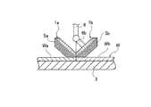
本実施形態に係る接合装置は、図1に示すように、受け部材3上で、平行に並べられた帯状ゴム材料Wの端部Wa、Wb同士を接合する装置であり、一定の角度で配置された、円周外周に溝5a、5bが彫られた円錐台形状の1対のローラ1a、1bを備える。図1では、ローラ1a、1bの上部に歯車が形成され、互いに噛み合わされている。このため、ローラ1bに接合されたローラ回転軸6bを回転させることにより、ローラ1b及びローラ1aを回転させることができる。尚、ローラ1a、1bに歯車を形成せず、ローラ1a側にもローラ回転軸を有する構成としても構わない。又、ローラ回転軸6bは、ローラ1a、1bを支える支持部材6と接合される。
(Joining equipment)
As shown in FIG. 1, the joining device according to the present embodiment is a device that joins the end portions Wa and Wb of the belt-like rubber materials W arranged in parallel on the receiving
ここで、帯状ゴム材料Wとしては、例えば、タイヤ構成材料として使用されるカーカスが挙げられる。カーカス形成用のプライ材料は、コードを長手方向に平行配列したゴム被覆材をタイヤの種類やサイズ等によって定まるカーカス巾に対応した長さで一端切断し、そのゴム被覆材のコードに沿う端部Wa、Wbを順次接合することにより、所定巾のカーカスプライ材料が形成される。 Here, examples of the belt-like rubber material W include carcass used as a tire constituent material. The carcass forming ply material is cut at one end with a length corresponding to the carcass width determined by the type and size of the tire, and ends along the cord of the rubber covering material. By sequentially joining Wa and Wb, a carcass ply material having a predetermined width is formed.
帯状ゴム材料Wの接合は、1対のローラ1a、1bを、接合する部材の端部Wa、Wbに接触させ、ローラ1a、1bが回転することにより、当該溝が端部同士を寄せ合い、ジッパー機能(ネジ効果)により行われる。
The band-shaped rubber material W is joined by bringing the pair of
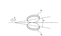
ローラ1a、1bは、互いに背中合わせで接近して位置し、背面が水平方向の一方、及び垂直方向の上方に拡開する。図2に示すように、ローラ1a、1bは、水平方向にα拡開し、矢印A方向に帯状ゴム材料Wの隣り合う端部Wa、Wbに沿って移動することにより、端部Wa、Wb同士の圧着接合を行う。
The
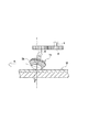
又、ローラ1a、1bは、図3に示すように、垂直方向の上方にθ拡開している。言い換えると、ローラ1a、1bの帯状ゴム材料Wの接触面と、歯車の噛み合う点の角度はθである。
Further, as shown in FIG. 3, the
支持部材6は、その上部に設けられた第1の歯車7に接合され、第1の歯車7と第2の歯車8とは、互いに噛み合わされている。このため、歯車回転軸9を回転させることにより、第2の歯車8及び第1の歯車7を回転させることができる。尚、第1の歯車7及び第2の歯車8は、受け部材3に対して水平方向に回転する。
The
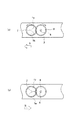
図3において、ローラ1a、1bは、矢印A方向に移動していたとする。このとき、第1の歯車7が回転することにより、ローラ1a、1bが水平方向に回転する。即ち、図4(a)に示す状態であったローラ1a、1bは、第2の歯車8及び第1の歯車7が回転することにより、図4(b)に示すように、水平方向に180°回転することができる。図4(b)に示す状態のローラ1a、1bは、矢印Aとは正反対の方向である矢印Bの方向へ移動することができる。又、このとき、水平方向の拡開角度α及び垂直方向の拡開角度θは保持したまま、ローラ1a、1bは回転する。
In FIG. 3, it is assumed that the
図3及び図4において、歯車を用いてローラを水平方向に回転させる機構について説明したが、他の機構を用いてローラを水平方向に回転させても構わない。 3 and 4, the mechanism for rotating the roller in the horizontal direction using the gears has been described. However, the roller may be rotated in the horizontal direction using another mechanism.
例えば、図5に示すように、ローラの支持部材6に接合された、水平方向に回転するベアリング10機構を用いて回転を行っても構わない。ベアリング10内には、ベアリングの玉が保持され、転がり軸受けとして機能する。このベアリング機構により、ローラ1a、1bは、図5の点線で示すように、水平方向に180°回転することができる。
For example, as shown in FIG. 5, rotation may be performed using a bearing 10 mechanism that is joined to a
尚、ローラ1a、1b、第1の歯車7、第2の歯車8、ベアリング10等を回転させる駆動源については特に図示していないが、接合装置に応じたモータなどが適宜使用できることは勿論である。
A drive source for rotating the
(接合方法)
次に、本実施形態に係る接合方法について説明する。
(Joining method)
Next, the joining method according to this embodiment will be described.
まず、接合装置の受け部材3上に、帯状ゴム材料Wの端部Wa、Wb同士を平行に並べる。そして、一定の角度で配置された、円周外周に溝5a、5bが彫られた円錐台形状の1対のローラ1a、1bを帯状ゴム材料Wの端部Wa、Wbにそれぞれ接触させる。
First, the end portions Wa and Wb of the belt-like rubber material W are arranged in parallel on the receiving
次に、1対のローラ1a、1bを回転させることにより、当該溝5a、5bが端部Wa、Wb同士を寄せ合い、ジッパー機能により圧着接合を行う。所定の位置まで接合が終わると、1対のローラ1a、1bを水平方向に上昇させ、帯状ゴム材料Wから離す。
Next, by rotating the pair of
そして、上述した歯車やベアリング等の回転手段を用い、1対のローラ1a、1bを水平方向に180°回転させる。即ち、図4(a)の状態から図4(b)の状態へ回転させる。
Then, using the rotating means such as the gears and bearings described above, the pair of
次に、180°回転させた1対のローラ1a、1bを下降させ、帯状ゴム材料Wの所定の端部Wa、Wbにそれぞれ接触させる。そして、1対のローラ1a、1bを回転させることにより、当該溝5a、5bが端部Wa、Wb同士を寄せ合い、当初とは正反対の方向に移動することにより、圧着接合を行う。
Next, the pair of
尚、1対のローラ1a、1bを180°回転させた後、所定の位置まで移動させた後、下降させてもよく、帯状ゴム材料Wの接合が完了した場合は、次の帯状ゴム材料Wを受け部材3上にセットした後、下降させてもよい。
The pair of
(作用及び効果)
本実施形態に係る接合装置及び接合方法によると、1対のローラ1a、1bが水平方向の拡開角度α及び垂直方向の拡開角度θを保持したまま水平方向に回転することができる。このため、1対のローラ1a、1bが往復運動をすることが可能となる。
(Action and effect)
According to the joining apparatus and joining method according to the present embodiment, the pair of
従来、部材の中央部より両側へ接合を行う場合は、1方向へ進行する1対のローラと、当該1対のローラとは反対の方向へ進行する1対のローラ、計2対のローラを用意する必要があった。具体的には、1対のローラAと1対のローラBを備える場合、最初、1対のローラAが開始位置へ接触し、特定の方向へ接合を開始する(ステップS1)。1対のローラAがスタートした後、1対のローラBが当該開始位置へ接触し、ローラAとは正反対の方向へ接合を開始する(ステップS2)。そして、ローラAは接合を完了した後、上昇し、開始位置へ戻り、待機状態となる(ステップS3)。又、ローラBも接合を完了した際、上昇し、開始位置へ戻り、待機状態となり(ステップS4)、ステップS1へと戻る。 Conventionally, when joining from the center of a member to both sides, two pairs of rollers, one pair of rollers traveling in one direction and one pair of rollers traveling in the opposite direction of the pair of rollers, are combined. It was necessary to prepare. Specifically, when a pair of rollers A and a pair of rollers B are provided, first, the pair of rollers A contacts the start position and starts joining in a specific direction (step S1). After the pair of rollers A is started, the pair of rollers B comes into contact with the start position, and starts joining in the direction opposite to the roller A (step S2). Then, after completing the joining, the roller A rises, returns to the start position, and enters a standby state (step S3). Further, when the joining of the roller B is completed, the roller B rises, returns to the start position, enters a standby state (step S4), and returns to step S1.
本実施形態に係る接合装置は、1対のローラ1a、1bを用いることにより、部材の中央部より両側へ接合を行うことができる。具体的には、1対のローラ1a、1bが中央部から一方の端部側へ接合を行った後、1対のローラ1a、1bを180°回転させ、中央部へ戻し、中央部から他方の端部側へ接合を行う。このように、本実施形態に係る接合装置及び接合方法によると、2対のローラを用意する必要がないため、設備費用を削減することができる。
By using a pair of
又、従来の接合装置は、1方向へしか進行できないため、部材の接合が終わると開始位置までローラを戻す動作が必要であったが、本実施形態に係る接合装置は、1対のローラで往復運動をすることができるため、ローラを開始位置まで戻す必要がない。従って、稼働時間(稼働サイクル)を減少することができる。例えば、一の部材の接合が完了した場合、その完了位置で1対のローラ1a、1bを180°回転させる。そして、次の部材をセットし、その位置でローラ1a、1bを下降させ、次の部材の開始位置とすることができる。
In addition, since the conventional joining apparatus can only proceed in one direction, it is necessary to return the roller to the start position when the joining of the members is completed. However, the joining apparatus according to the present embodiment includes a pair of rollers. Since it can reciprocate, it is not necessary to return the roller to the start position. Therefore, the operation time (operation cycle) can be reduced. For example, when the joining of one member is completed, the pair of
1a、1b…ローラ、3…受け部材、5a、5b…溝、6…支持部材、6b…ローラ回転軸、7…第1の歯車、8…第2の歯車、9…歯車回転軸、10…ベアリング、W…帯状ゴム材料、Wa、Wb…端部、A、B…移動方向
DESCRIPTION OF
Claims (4)
互いに背中合わせで接近して位置し、背面が水平方向の一方、及び垂直方向の上方に拡開し、当該水平方向に拡開した方向に前記部材の隣り合う端部に沿って移動することにより、前記端部同士の圧着接合を行う円錐台形状の1対のローラと、
該1対のローラを水平方向に回転させる回転手段と
を備えることを特徴とする接合装置。 A joining apparatus for joining adjacent ends of members arranged in parallel,
By being positioned close to each other back to back, the back surface expands in the horizontal direction and upward in the vertical direction, and moves along the adjacent end portions of the member in the horizontal expanded direction, A pair of frustoconical rollers for pressure bonding between the ends;
Welding apparatus comprising: a rotating means for rotating the roller of the pair in the horizontal direction.
互いに背中合わせで接近して位置し、背面が水平方向の一方、及び垂直方向の上方に拡開した円錐台形状の1対のローラを、当該水平方向に拡開した方向に、前記部材の隣り合う端部に沿って移動させることにより、前記端部同士の圧着接合を行う第1のステップと、
該1対のローラを水平方向に回転させる第2のステップと、
該1対のローラを、前記第1のステップにおける移動方向とは正反対の方向に、前記部材の隣り合う端部に沿って移動させることにより、前記端部同士の圧着接合を行う第3のステップと
を含むことを特徴とする接合方法。 A joining method for joining adjacent ends of members arranged in parallel,
A pair of frustoconical rollers, which are located close to each other back to back and whose rear surfaces are expanded in the horizontal direction and in the vertical direction, are adjacent to each other in the horizontal direction. A first step of performing crimp bonding of the ends by moving along the ends; and
A second step of rotating the roller of the pair in the horizontal direction,
A third step of performing the pressure bonding of the end portions by moving the pair of rollers along adjacent ends of the member in a direction opposite to the moving direction in the first step. And a bonding method characterized by comprising:
Priority Applications (1)
| Application Number | Priority Date | Filing Date | Title |
|---|---|---|---|
| JP2004229538A JP4668564B2 (en) | 2004-08-05 | 2004-08-05 | Joining apparatus and joining method |
Applications Claiming Priority (1)
| Application Number | Priority Date | Filing Date | Title |
|---|---|---|---|
| JP2004229538A JP4668564B2 (en) | 2004-08-05 | 2004-08-05 | Joining apparatus and joining method |
Publications (2)
| Publication Number | Publication Date |
|---|---|
| JP2006044105A JP2006044105A (en) | 2006-02-16 |
| JP4668564B2 true JP4668564B2 (en) | 2011-04-13 |
Family
ID=36023214
Family Applications (1)
| Application Number | Title | Priority Date | Filing Date |
|---|---|---|---|
| JP2004229538A Expired - Fee Related JP4668564B2 (en) | 2004-08-05 | 2004-08-05 | Joining apparatus and joining method |
Country Status (1)
| Country | Link |
|---|---|
| JP (1) | JP4668564B2 (en) |
Family Cites Families (6)
| Publication number | Priority date | Publication date | Assignee | Title |
|---|---|---|---|---|
| IT1190035B (en) * | 1986-06-05 | 1988-02-10 | Pirelli | METHOD AND APPARATUS FOR HEAD-TO-HEAD JOINT OF RUBBER FABRIC SHEETS |
| US5221409A (en) * | 1992-01-06 | 1993-06-22 | The Goodyear Tire & Rubber Company | Apparatus for butt splicing ply stock |
| JP3442468B2 (en) * | 1994-04-05 | 2003-09-02 | 東洋ゴム工業株式会社 | Steel ply bonding equipment for radial tires |
| JP3045459B2 (en) * | 1995-03-07 | 2000-05-29 | 住友ゴム工業株式会社 | Carcass ply end joining device |
| JP2002166479A (en) * | 2000-09-25 | 2002-06-11 | Yokohama Rubber Co Ltd:The | Method for connecting strip-like rubber material |
| JP2003019761A (en) * | 2001-07-09 | 2003-01-21 | Yokohama Rubber Co Ltd:The | Method for laminating strip-shaped rubber materials and molding drum to be used in this laminating method |
-
2004
- 2004-08-05 JP JP2004229538A patent/JP4668564B2/en not_active Expired - Fee Related
Also Published As
| Publication number | Publication date |
|---|---|
| JP2006044105A (en) | 2006-02-16 |
Similar Documents
| Publication | Publication Date | Title |
|---|---|---|
| CN101410193B (en) | Ring rolling mill and ring rolling method | |
| JP2010006585A (en) | Rectangular wire winding device and winding method | |
| JP7122271B2 (en) | Friction stir welding apparatus and friction stir welding method | |
| KR101317876B1 (en) | Separation method of bonded substrate | |
| JP2011212858A (en) | Joining device and manufacturing method of tire component member | |
| JP4668564B2 (en) | Joining apparatus and joining method | |
| JP7001401B2 (en) | Roller hemming device | |
| CN105711073A (en) | A groove forming device for a sheet-shaped part and a groove forming method | |
| JP2011218739A (en) | Device for producing tire constituting member and method for producing the same | |
| JP2011046025A (en) | Apparatus and method for manufacturing bead member | |
| JP2019195902A (en) | Cutting mechanism for roll fiber product | |
| JP4753649B2 (en) | Manufacturing method and manufacturing apparatus of tire constituent member. | |
| EP3222593B1 (en) | Method for splitting glass plate | |
| JP4704783B2 (en) | Bead apex joint device | |
| JP2007062041A (en) | Method and apparatus for applying sheetlike member to drum | |
| JP4015671B2 (en) | Deburring device | |
| KR100466234B1 (en) | A Structure of Stitcher for Tire | |
| JP3788456B2 (en) | Tailored blank material continuous welding equipment | |
| JP5697960B2 (en) | Sheet rubber member joining device | |
| JP2014051369A (en) | Winding device, and winding method | |
| JP5455484B2 (en) | Tread member crimping apparatus and tire manufacturing apparatus | |
| JP6059583B2 (en) | Rubber strip sticking device | |
| JP2007283343A (en) | Drawing method and its apparatus | |
| JP4410901B2 (en) | Processing method and processing apparatus for tire carcass ply material | |
| WO2011148942A1 (en) | Bag making machine |
Legal Events
| Date | Code | Title | Description |
|---|---|---|---|
| A621 | Written request for application examination |
Free format text: JAPANESE INTERMEDIATE CODE: A621 Effective date: 20070702 |
|
| A977 | Report on retrieval |
Free format text: JAPANESE INTERMEDIATE CODE: A971007 Effective date: 20100312 |
|
| A131 | Notification of reasons for refusal |
Free format text: JAPANESE INTERMEDIATE CODE: A131 Effective date: 20100316 |
|
| A521 | Request for written amendment filed |
Free format text: JAPANESE INTERMEDIATE CODE: A523 Effective date: 20100517 |
|
| TRDD | Decision of grant or rejection written | ||
| A01 | Written decision to grant a patent or to grant a registration (utility model) |
Free format text: JAPANESE INTERMEDIATE CODE: A01 Effective date: 20110111 |
|
| A01 | Written decision to grant a patent or to grant a registration (utility model) |
Free format text: JAPANESE INTERMEDIATE CODE: A01 |
|
| A61 | First payment of annual fees (during grant procedure) |
Free format text: JAPANESE INTERMEDIATE CODE: A61 Effective date: 20110113 |
|
| FPAY | Renewal fee payment (event date is renewal date of database) |
Free format text: PAYMENT UNTIL: 20140121 Year of fee payment: 3 |
|
| R150 | Certificate of patent or registration of utility model |
Free format text: JAPANESE INTERMEDIATE CODE: R150 |
|
| LAPS | Cancellation because of no payment of annual fees |