JP4668496B2 - Method and apparatus for driving a quadrupole ion trap device - Google Patents
Method and apparatus for driving a quadrupole ion trap device Download PDFInfo
- Publication number
- JP4668496B2 JP4668496B2 JP2001531124A JP2001531124A JP4668496B2 JP 4668496 B2 JP4668496 B2 JP 4668496B2 JP 2001531124 A JP2001531124 A JP 2001531124A JP 2001531124 A JP2001531124 A JP 2001531124A JP 4668496 B2 JP4668496 B2 JP 4668496B2
- Authority
- JP
- Japan
- Prior art keywords
- ion trap
- time
- voltage
- quadrupole ion
- ions
- Prior art date
- Legal status (The legal status is an assumption and is not a legal conclusion. Google has not performed a legal analysis and makes no representation as to the accuracy of the status listed.)
- Expired - Fee Related
Links
Images


Classifications
-
- H—ELECTRICITY
- H01—ELECTRIC ELEMENTS
- H01J—ELECTRIC DISCHARGE TUBES OR DISCHARGE LAMPS
- H01J49/00—Particle spectrometers or separator tubes
- H01J49/26—Mass spectrometers or separator tubes
- H01J49/34—Dynamic spectrometers
- H01J49/42—Stability-of-path spectrometers, e.g. monopole, quadrupole, multipole, farvitrons
- H01J49/426—Methods for controlling ions
- H01J49/427—Ejection and selection methods
-
- H—ELECTRICITY
- H01—ELECTRIC ELEMENTS
- H01J—ELECTRIC DISCHARGE TUBES OR DISCHARGE LAMPS
- H01J49/00—Particle spectrometers or separator tubes
- H01J49/02—Details
- H01J49/022—Circuit arrangements, e.g. for generating deviation currents or voltages ; Components associated with high voltage supply
-
- H—ELECTRICITY
- H01—ELECTRIC ELEMENTS
- H01J—ELECTRIC DISCHARGE TUBES OR DISCHARGE LAMPS
- H01J49/00—Particle spectrometers or separator tubes
- H01J49/26—Mass spectrometers or separator tubes
- H01J49/34—Dynamic spectrometers
- H01J49/42—Stability-of-path spectrometers, e.g. monopole, quadrupole, multipole, farvitrons
- H01J49/426—Methods for controlling ions
- H01J49/4295—Storage methods
Description
【0001】
(発明の分野)
本発明は、四重極質量分光法に関する。特に、本発明は、線形または3D回転対称四重極イオントラップ装置のような四重極イオントラップ装置を駆動する方法と装置に関する。また、本発明は、前記方法と装置を使用しかつ組み込んだ四重極装置に関する。
【0002】
(発明の背景)
質量分析のために四重極質量分析器と四重極イオントラップを使用する最初の考え方は、米国特許第2,939,952号でW.ポール(W.Paul)とH.シュタインウェーデル(H.Steinwedel)によって開示された。一般に、四重極イオントラップ質量分光法では、2つの異なった電極構造が使用される。すなわち、添付図面の図1a及び図1bでそれぞれ例示される、線形四重極イオントラップ構造と3D回転対称四重極イオントラップである。図1aを参照すると、線形四重極イオントラップ構造には、1対のx電極1、1対のy電極2、イオン入射プレート3及びイオン出射プレート4が含まれる。2つのプレート3、4は、イオンが逃散するのを防止する電位障壁を設定するために使用される。図1bを参照すると、四重極イオントラップ構造には、リング電極1と、エンドキャップ電極2、3が含まれ、エンドキャップ電極2には中央穴4が存在する。こうした構造を質量分析器として機能させるためには、時間の関数としての周期的な変化を有する電圧を電極間に印加する必要がある。米国特許第2,939,952号は、この周期電圧を達成するためDC電圧と結合された正弦高周波電圧を発生する方法を教示する。この電圧を印加すると、イオンの運動を駆動する四重極電界が形成される。マシュー方程式の解に基づくイオン運動の理論が確立されている。この理論は四重極質量分光法のその後の開発において他の者によって広く使用されており、関連教科書「四重極蓄積型質量分光法(“Quadrupole Storage Mass Spectrometry”)」、E.マーチ(E.March)、R.J.ヒューズ(R.J.Hughes)著、ワイリー−インターサイエンス・パブリケーション(Wiley−Interscience Publication)刊で紹介されているが、そこでは正弦高周波電圧は普通無線周波(RF)電圧と呼ばれている。
【0003】
1980年代には、イオントラップ質量分光法について多くの技術的進歩があった。とりわけ、米国特許第4,540,884号で開示された質量選択不安定モードでの動作と、米国特許第4,736,101号で開示された質量選択共振放出の使用は、四重極イオントラップの性能の顕著な改善に結びつき、装置は高速かつ高解像度の質量分析とタンデム質量分析が実行できるようになった。
【0004】
その後、米国特許第5,629,186号で開示されたイメージ電流のフーリエ変換のような異なった検出方法も開発された。こうした発展は、質量分光法及び質量分光法と他の広く使用されている機器との組み合わせにおいて非常に多くの応用をもたらした。
【0005】
根本的に、この技術は、重畳したRFとDCの四重極電界中、または場合によっては純粋なRF電界中のイオン運動に基づいているので、全ての応用は四重極装置にRF電圧を供給するRF電源を必要とする。従来、RF電源は、負荷として四重極イオン光学装置を含む駆動電気回路及び共振ネットワークを備えている。ネットワークの共振周波数は、普通固定されており、または少数の固定値を有する。質量走査または質量選択を達成するため、RF電源の出力電圧は望ましいスキームに従って正確に増加し減少しなければならず、RF電圧の振幅は、RF周波数が固定値の場合質量対電荷比に比例する。高質量分析のためには高RF電圧が必要である。また、時として、出力電圧の変化によって発生するネットワークの共振位置における許容できない変動を修正する必要がある。こうした要因の結果、機器の費用と複雑さが増大する。
【0006】
「ポールトラップ中のマトリックス支援レーザ脱着/イオン化によって発生する高質量イオンの分析のための周波数走査(“Frequency Scan for the Analysis of High Mass Ions Generated by Matrix−assisted Laser Desorption/Ionization in a Paul Trap”)」と題された論文(U.P.シュルネッガー(U.P.Schlunegger)他、高速通信質量分光法(Rapid.Commun.Mass.Spectrom.)13、1792−1796、1999年)は、電圧走査技術の代わりに周波数走査技術を使用して、MALDIイオントラップ分光計の四重極イオントラップの質量走査範囲を改善することを開示する。そこで説明される技術は、高い質量対電荷比を有する生体分子イオンをトラップし分析するのに特に適している。波形発生器と電源が使用され周波数可変正弦波電圧を提供した。この電圧出力は、基本的にアナログ回路であり線形状態で動作しなければならない増幅器の電力消費量によって制限されている。従って、さらに高いRF電圧が必要な場合、この構成では、電力消費量と、ひいては機械の寸法及び製造費用を低下させることは困難である。
【0007】
実際には、原開示でW.ポール他によって述べられているように、四重極イオントラップまたは四重極質量分析器を駆動するために正弦RF電圧を使用する必要はない。E.P.シェレトフ(E.P.Sheretov)他は論文「パルス給電の際の四重極質量分光計の理論の基礎(“Basis of the theory of quadrupole mass spectrometers during pulse feeding”)」(テレンチェフ記念技術物理学雑誌(Zh.V.I.Terent’ev,Tech.Fiz)、1972年、42(5) 953−962)は、電圧パルスを印加する際の四重極質量分光計におけるイオンの挙動に関する詳細な議論を示している。さらに、GB 1346393は、矩形または台形波電圧で四重極質量フィルタを駆動する方法を開示している。しかし、矩形波駆動の真の利点は、デジタル周波数走査とタイミング制御に関連している。これは先行技術によっては明らかにされていない。高性能MS及びMSnを達成する四重極イオントラップの矩形波駆動と結合する特定の方法はまだ提供されていない。
【0008】
本発明の方法は、イオントラップ、選択及び/または質量分析のため四重極イオントラップ装置に印加される時間変化矩形波を利用する。
【0009】
(発明の概要)
本発明の1つの態様によれば、四重極イオントラップ装置を駆動する方法であって、デジタル信号を形成するステップと、1組のスイッチを制御して、スイッチが高電圧レベルと低電圧レベルとを交互に切り換えて時間変化矩形波電圧を生成するようにするためデジタル信号を使用するステップと、所定の範囲の質量対電荷比でイオンをトラップするため時間変化矩形波電圧を四重極イオントラップ装置に供給するステップと、四重極イオントラップ装置によってトラップされるイオンの所定の範囲の質量対電荷比を変化させるためデジタル信号を変化させるステップと、装置中でイオンの質量選択共振振動運動を発生させるため四重極イオントラップ装置に時間変化双極励起電圧をさらに供給するステップ、を含む方法が提供される。
【0010】
本発明の別の態様によれば、四重極イオントラップ装置を駆動する装置と、デジタル信号を形成する手段と、スイッチが高電圧レベルと低電圧レベルとを交互に切り換えて、使用の際所定の範囲の質量対電荷比でイオンをトラップするため前記四重極イオントラップ装置に供給される時間変化矩形波電圧を生成するようにするため前記デジタル信号によって制御されるよう配置される1組のスイッチと、四重極イオントラップ装置によってトラップされるイオンの所定の範囲の質量対電荷比を変化させるため前記デジタル信号を変化させる手段と、装置中でイオンの質量選択共振振動運動を発生させるため四重極イオントラップ装置に時間変化双極励起電圧を供給する手段とが提供される。
【0011】
前記四重極イオントラップ装置は、線形四重極質量分析器または3D回転対称四重極イオントラップまたはイオンを蓄積及び/または質量分析する四重極電界を生成するために使用される何らかの他のイオントラップ構造である。
【0012】
(好適実施形態の説明)
図2に示される矩形波電圧は、高電圧レベルV1での幅w1と、低電圧レベルV2での幅w2とを有する。この例では、矩形波電圧は次式によって示されるDCオフセットU、
U=(w1V1+w2V2)/(w1+w2) (1)
と、次式によって示される反復率fとを有する。
【0013】
f=(w1+w2)1 (2)
【0014】
図3aは、図2の矩形波電圧を生成する駆動装置の例を示す。この駆動装置には、高周波数で高精度のクロック信号12を生成するクロック11が含まれる。計数ユニット13は、いくつかのカウンタと、各カウンタ中の事前設定された数の計数によって設定または再設定される出力ゲートとを有する。カウンタの数は必要な矩形波パターンの複雑さに依存する。ここで示される例では、矩形波パターンの幅w1、w2を決定する事前設定された数のカウント数Nw1、Nw2によって出力ゲートを設定または再設定する2つのカウンタが存在する。カウント数Nw1、Nw2を設定する質量走査制御ユニット14は、質量走査、すなわちイオンの質量対電荷比の走査の際の出力デジタル・パターンとその変化を制御するようプログラムされている。
【0015】
次に、必要なパルス・パターンを有するデジタル信号15は、スイッチ16とスイッチ17とを含むスイッチ回路に供給される。スイッチ16及び17は通常バイポーラまたはFETトランジスタである。スイッチ間で起こりうる電位差を克服し、スイッチが確実に必要な速度で動作するようにするため計数ユニット13とスイッチ16、17との間に適応回路が必要なことがある。スイッチ16は低レベルDC電源19(V2)に接続され、スイッチ17は高レベルDC電源18(V1)に接続される。スイッチ16、17がデジタル制御信号15によって交互に開閉すると、矩形波駆動電圧を形成する高及び低レベル電圧V1、V2が四重極装置に供給される。
【0016】
図3bは、矩形波電圧を生成する駆動装置のまた別の例を示す。この構成は、デジタル制御信号を生成するため直接デジタル・シンセサイザ(DDS)25と高速比較器26を使用する点で図3aのものと異なっている。DDS25は、かなりの高精度で、質量制御ユニット24によって事前設定されたある周波数の周期波形を発生する。デューティサイクルを制御するため質量制御ユニットによってしきい値が設定される高速比較器26の使用を通じて、デジタル信号15は正確に生成され、すでに説明された方法でスイッチ回路を制御するために使用される。
【0017】
さらに、付加双極励起電界を印加するために、AC励起電圧源22も使用される。双極励起電圧は、調和正弦波形、広帯域多重周波数波形または矩形波形といった広範な異なったAC波形を有する。
【0018】
3D四重極イオントラップの形態の四重極装置の場合、矩形駆動電圧がリング電極20に供給され、エンドキャップ電極は励起電圧源22に接続されるが、これはやはりリング電極に対して両方のエンドキャップ電極に共通DCバイアスを提供する。イオン運動を励起する矩形パルスを発生するため、励起電圧源はスイッチ回路の形態であることもあり、これは主デジタル信号15と所定の関係を有するデジタル信号によって制御される。
【0019】
矩形波電圧が方形波形(すなわち、V1=−V2、w1/w2=1)を有する最も簡単な場合、DC電源19はDC電源18と同じ電圧だが反対の極性を有する電圧に設定される。また、単一のDC電源18だけが使用され、スイッチ16は単に接地に接続されることもある。この場合、結果として生じるDC電圧オフセットは、両方のエンドキャップにDCバイアス電圧V1/2を印加することによってか、またはDCオフセットを隔離するため出力電圧をリング電極に容量性結合することによって打ち消される。
【0020】
線形四重極イオントラップの形態の四重極装置の場合、矩形駆動電圧が第1の対角対向電極対に供給され、もう1つの対角対向電極対各々はそれ自体同様のスイッチ回路によって駆動される。第2の対角対向電極対のスイッチングは普通第1対のスイッチングと同期し逆相であり、対称四重極界を形成する。しかし、それらのタイミングが故意に異なって制御されている場合、双極励起電界が形成され、駆動四重極界と重なり合う。
【0021】
矩形波電圧によって駆動されると、四重極イオントラップ中のイオン運動は、四重極質量分光法の上述の初期の理論の根底をなすマシュー方程式によって解くことはできない。
【0022】
しかし、時間変化矩形波電圧によって生成される四重極界中のイオン運動は、異なった時間区分でニュートン方程式を適用することによって定義できる。各区分内で電界は一定であるので、この方程式は容易に解くことができる。
【0023】
以下イオン運動の理論的導出の一例を簡単に示す。
【0024】
ここでは、図2に示される形態の矩形波形が標準四重極イオントラップに印加される(r0=√2z0)。例示を容易にするため、波形はDCオフセットがないのでV1=−V2=Vであると想定され、またw1/w2=1であると想定される。これは、+/−Vの一定の値の間で交替する電圧が各半サイクルの間イオントラップのリング電極に印加されるということを意味する。すなわち、z方向のイオン運動は以下の微分方程式によって決定される(r方向の運動も同様の方法を使用して導出されるが、2つの運動は独立である)。
【0025】
【数1】

正確な解が正の半サイクルについて次式のように得られ、
z=Ceλ t+De- λ t (4a)
負の反サイクルについて次式のように得られるが、
z=Gcos(λt)+Hsin(λt) (4b)
ここで、C、D、G、Hは半サイクル開始時の条件とλ=(qz/2)1/2Ωから導出される。ここで、Ω=2πfは矩形波の反復率を表し、qzは、2つの種類の運動の間の比較を容易にするため、従来のRF駆動四重極イオントラップについて同じ定義、すなわち次式を有する。
【0027】
qz=4eV/mΩ2r0 2 (5)
また、イオンの軌道は、2つの位相空間トランスファー行列を使用して計算することもできる。すなわち、
正の半サイクルについて次式であり、
【0028】
【数2】
【0029】
【数3】
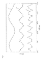
図4に示される曲線は、上記の行列計算に基づく数値計算によって得られるz方向の運動について時間の関数としてのイオン位置を表す。図4で参照符号1、2、3によって示される曲線はそれぞれqz=0.15、0.3及び0.6であり、これらの値が有界(または安定)イオン運動の範囲内にあることが明らかである。
【0031】
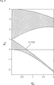
矩形波電圧がDCオフセットを有する場合、パラメータazもマシュー方程式を使用して定義される、すなわちaz=−8eU/mΩ2r0 2である。a−q安定性の図が図5でw1/w2=1の場合についてグラフ化されているが、そこでは斜線部が、イオンの運動が安定であるaz及びqzの値を示している。これが示すところによれば、矩形波電圧を印加することによって、イオンは安定運動を経験するイオンと不安定運動を経験するイオンとに分離されるので、イオンはイオントラップ内部に蓄積されるある基準を満足できるようになる。
【0032】
GB1346393号及び同じ発明者による論文は、矩形波のデューティサイクルを変化させることによって安定領域の帯域幅を選択し、矩形波電圧の振幅を走査することによって質量走査を実行する方法を開示している。しかし、質量走査の代替的でさらに好ましい方法が存在している。
【0033】
図4に示される詳細な運動は複雑であるが、各曲線に対する主発振周波数は明白に理解される。シェレトフ他による上記の論文で提示された理論に基づくさらなる理論的研究が示すところによれば、qzの値がさらに小さくなると、方形波の場合この発振の角周波数ωzは次式によって表される。
【0034】
【数4】
qzの値がさらに小さくなると、これは次式のように単純化される。
【0036】
【数5】
【0037】
共振点またはその付近で、こうしたイオンは選択的に励起され、さらにはイオントラップから放出されるので、外部検出器によって検出される。また、共振励起によって選択されたイオンの運動エネルギーが増大し、ある種の化学反応が促進されたりフーリエ変換検出のためのイメージ電流が誘発されたりすることがある。
【0038】
ここで、この共振作用の1つの実現が、一方または両方のエンドキャップに穴を有する従来の3D四重極イオントラップを使用する例によって説明される。励起AC電圧は、単一周波数の正弦電圧または矩形波電圧、または複数の周波数成分から構成される波形である。この電圧が2つのエンドキャップの間に印加され、その周波数成分の1つω0がωzに近づくと、z方向のイオン運動が共振によって励起される。共振イオンの発振振幅は、イオンがエンドキャップ電極に達するか、またはエンドキャップ穴を通じて放出されるまで増大する。固有周波数ωzは質量対電荷比、反復率f及び矩形波電圧を定義する電圧の関数であるので、望ましい共振技術を使用する質量走査は以下のような様々な方法で実現される。
【0039】
1.駆動矩形波形の反復率fを固定し、例えば0からπfまでの励起周波数ω0を走査する。
【0040】
2.デジタル周波数分割器を使用して励起周波数ω0をfに比例させ、それによってqzの値を固定して反復率fを走査する。デジタル計数法を使用してデジタル制御信号を生成する場合、Nw1及びNw2の値を増減することによって反復率fが変化する。
【0041】
3.励起周波数ω0を固定して駆動矩形波電圧の反復率fを走査する。上記の方程式(8)及び(5)から次式の通りであることが見られるが、これは、矩形波周期の設定を直線的に増大することによって質量走査がほぼ直線的になることを示している。
【0042】
【数6】
上記の導出は、DCオフセットがゼロである対称矩形波電圧の場合であるが、認識されるように、有限DCオフセット及び他の矩形波形パターンも本発明の範囲内である。理解されるように、実際には、矩形波電圧を生成するために使用されるスイッチング回路はスイッチング速度が制限されており、電流の制限を受けやすい。従って、矩形波形は小さな立ち上がりおよび立下り時間を有する。駆動矩形波形の電圧は質量走査の間固定されていたが、異なった電圧を使用することによって異なった質量走査範囲が得られる。周波数範囲が方程式(7)または(8)を使用して決定される広帯域励起と組み合わされたイオンの運動を駆動する矩形波電圧の印加も本発明の範囲内である。
【0044】
広帯域励起の場合、米国特許第5134286号及び第4761545号の教示のように広帯域波形生成器が使用されることもある。
【0045】
一般に、矩形波電圧駆動四重極質量分光法は現在のRF駆動四重極質量分光法と比較して下記の利点を有する。
【0046】
矩形波電圧は、LC共振器を利用しないスイッチング回路を使用して生成されるので、周波数または波の反復速度は容易に変更できる。現実的な範囲は10kHz〜10MHzである。四重極電界中のイオン運動の特性から知られるように、質量走査の範囲は、ある現実的な限界(例えば、高電圧での放電)内で電圧を変化させることよりも周波数を変化させることによってさらに幅広くなる。
【0047】
矩形波形は、例えば振幅、反復率、各サイクル中の遷移数とそれらの分離といった、正弦波形の場合より多くのパラメータを使用して定義できる。こうしたパラメータはイオンを蓄積し操作するより多くのオプションを提供する。例えば、矩形波形パターンは、外部イオン源からのイオンが四重極装置に導入される間、断続的または一時的に容易に変更できる。
【0048】
矩形波電圧を生成するために使用されるスイッチング回路の電力消費は、RF駆動電圧を生成するために使用される非同調アナログ回路より小さい。これは関連電子装置の電力仕様の低減につながる。
【0049】
現在、矩形波形を高精度と低費用で生成できる多数の高度デジタルスイッチング装置が存在している。小型または「オンチップ」四重極質量分析器またはイオントラップは開発中であるが、高集積駆動回路も必要とされている。矩形波電圧を定義する完全デジタル駆動信号を使用することによって、回路の複雑さは低減され、装置の寸法と費用は、機器全体の費用と共に最小化される。
【図面の簡単な説明】
【図1a】 周知の線形形態の四重極イオントラップ構造を示す図。
【図1b】 周知の3−D回転対称四重極イオントラップ構造を示す図。
【図2】 本発明による時間変化矩形波電圧を示す図。
【図3a】 四重極イオントラップで使用される本発明による駆動装置の1つの実施形態を示す構成概略図。
【図3b】 四重極イオントラップで使用される本発明による駆動装置の別の実施形態を示す構成概略図。
【図4】 異なった矩形波電圧によって駆動される四重極イオントラップ中のイオン運動の特性を示す図。
【図5】 z方向のみのイオン運動に関するa対qのグラフ中の安定領域(斜線で示す)を例示する図。[0001]
(Field of Invention)
The present invention relates to quadrupole mass spectroscopy. In particular, the present invention relates to a method and apparatus for driving a quadrupole ion trap device, such as a linear or 3D rotationally symmetric quadrupole ion trap device. The invention also relates to a quadrupole device using and incorporating the method and apparatus.
[0002]
(Background of the Invention)
The first idea of using a quadrupole mass analyzer and a quadrupole ion trap for mass spectrometry is described in US Pat. Paul (W. Paul) and H. Paul Disclosed by H. Steinwedel. In general, quadrupole ion trap mass spectroscopy uses two different electrode structures. That is, a linear quadrupole ion trap structure and a 3D rotationally symmetric quadrupole ion trap, respectively illustrated in FIGS. 1a and 1b of the accompanying drawings. Referring to FIG. 1 a, the linear quadrupole ion trap structure includes a pair of
[0003]
In the 1980s, there were many technical advances in ion trap mass spectroscopy. In particular, the operation in the mass selective unstable mode disclosed in US Pat. No. 4,540,884 and the use of mass selective resonant emission disclosed in US Pat. The instrument was able to perform high speed and high resolution mass spectrometry and tandem mass spectrometry, resulting in significant improvements in trap performance.
[0004]
Later, different detection methods such as the Fourier transform of the image current disclosed in US Pat. No. 5,629,186 were also developed. These developments have resulted in numerous applications in mass spectroscopy and the combination of mass spectroscopy with other widely used instruments.
[0005]
Fundamentally, this technique is based on ion motion in superimposed RF and DC quadrupole fields, or in some cases pure RF fields, so all applications apply RF voltage to the quadrupole device. Requires RF power supply. Conventionally, an RF power source includes a driving electric circuit including a quadrupole ion optical device as a load and a resonance network. The resonant frequency of the network is usually fixed or has a small number of fixed values. In order to achieve mass scanning or mass selection, the output voltage of the RF power supply must increase and decrease exactly according to the desired scheme, and the amplitude of the RF voltage is proportional to the mass to charge ratio when the RF frequency is a fixed value . A high RF voltage is required for high mass analysis. Also, sometimes it is necessary to correct unacceptable variations in the resonant position of the network caused by changes in output voltage. These factors result in increased equipment cost and complexity.
[0006]
“Frequency Scan for the Analysis of High Mass Ions Generated by Matrix-Assessed Laser Deposition / High Ionization of the Mass-Assisted Laser Desorption / Ionization in the Pole Trap” (UP Schlumeger et al., Rapid Commun. Mass. Spectrom. 13, 1792-1796, 1999) is a voltage scanning technique. Discloses improving the mass scan range of a quadrupole ion trap of a MALDI ion trap spectrometer using frequency scanning technology instead of That. The technique described there is particularly suitable for trapping and analyzing biomolecular ions having a high mass to charge ratio. A waveform generator and power supply were used to provide a variable frequency sinusoidal voltage. This voltage output is limited by the power consumption of the amplifier, which is basically an analog circuit and must operate in a linear state. Thus, if higher RF voltages are required, it is difficult with this configuration to reduce power consumption and thus machine dimensions and manufacturing costs.
[0007]
Actually, in the original disclosure, W.W. As described by Paul et al., It is not necessary to use a sinusoidal RF voltage to drive a quadrupole ion trap or quadrupole mass analyzer. E. P. E. Sheretov et al. Published a paper entitled “Basis of the theory of quadrupole mass spectrometers pulsing the physics magazine”. (Zh. V. I. Terent'ev, Tech. Fiz), 1972, 42 (5) 953-962), a detailed discussion on the behavior of ions in a quadrupole mass spectrometer when applying a voltage pulse. Is shown. Furthermore, GB 1346393 discloses a method for driving a quadrupole mass filter with a rectangular or trapezoidal wave voltage. However, the true advantages of square wave drive are related to digital frequency scanning and timing control. This is not clarified by the prior art. No specific method has yet been provided to combine quadrupole ion trap square wave driving to achieve high performance MS and MS n .
[0008]
The method of the present invention utilizes a time-varying square wave applied to a quadrupole ion trap apparatus for ion trap, selection and / or mass spectrometry.
[0009]
(Summary of Invention)
According to one aspect of the present invention, a method of driving a quadrupole ion trap apparatus, comprising the steps of forming a digital signal and controlling a set of switches such that the switches are at a high voltage level and a low voltage level. Using a digital signal to alternately generate a time-varying rectangular wave voltage and a time-varying rectangular wave voltage to quadrupole ions to trap ions with a predetermined range of mass-to-charge ratios Supplying the trapping device, changing the digital signal to change the mass-to-charge ratio of the ions trapped by the quadrupole ion trapping device, and mass selective resonant oscillation motion of the ions in the device Further providing a time-varying dipole excitation voltage to the quadrupole ion trap device to generate.
[0010]
According to another aspect of the present invention, a device for driving a quadrupole ion trap device, means for forming a digital signal, and a switch alternately switches between a high voltage level and a low voltage level, so that a predetermined value can be used during use. A set arranged to be controlled by the digital signal to generate a time-varying rectangular wave voltage supplied to the quadrupole ion trap device for trapping ions at a mass to charge ratio in the range of A switch, means for changing the digital signal to change the mass-to-charge ratio of the ions trapped by the quadrupole ion trap device, and for generating mass selective resonant oscillation motion of the ions in the device Means are provided for providing a time-varying bipolar excitation voltage to the quadrupole ion trap device.
[0011]
The quadrupole ion trap device can be a linear quadrupole mass analyzer or a 3D rotationally symmetric quadrupole ion trap or any other used to generate a quadrupole field that accumulates and / or mass analyzes ions. It is an ion trap structure.
[0012]
(Description of preferred embodiment)
Rectangular wave voltage shown in FIG. 2 includes a width w 1 at a high voltage level V 1, and a width w 2 at a low voltage level V 2. In this example, the square wave voltage is a DC offset U given by:
U = (w 1 V 1 + w 2 V 2 ) / (w 1 + w 2 ) (1)
And a repetition rate f given by:
[0013]
f = (w 1 + w 2 ) 1 (2)
[0014]
FIG. 3a shows an example of a drive device that generates the rectangular wave voltage of FIG. The drive device includes a clock 11 that generates a high-
[0015]
Next, the
[0016]
FIG. 3b shows another example of a drive device that generates a rectangular wave voltage. This configuration differs from that of FIG. 3a in that a direct digital synthesizer (DDS) 25 and a
[0017]
In addition, an AC
[0018]
In the case of a quadrupole device in the form of a 3D quadrupole ion trap, a rectangular drive voltage is supplied to the
[0019]
In the simplest case where the square wave voltage has a square waveform (ie V 1 = −V 2 , w 1 / w 2 = 1), the
[0020]
In the case of a quadrupole device in the form of a linear quadrupole ion trap, a rectangular drive voltage is supplied to the first diagonal counter electrode pair, and each of the other diagonal counter electrode pairs is driven by a switch circuit similar to itself. Is done. The switching of the second diagonal counter electrode pair is usually synchronized and out of phase with the first pair of switching, forming a symmetric quadrupole field. However, if their timing is deliberately controlled differently, a dipole excitation field is formed and overlaps the driving quadrupole field.
[0021]
When driven by a square wave voltage, ion motion in a quadrupole ion trap cannot be solved by the Matthew equation that underlies the earlier theory of quadrupole mass spectroscopy.
[0022]
However, ion motion in a quadrupole field generated by a time-varying rectangular wave voltage can be defined by applying the Newton equation at different time intervals. Since the electric field is constant within each segment, this equation can be easily solved.
[0023]
An example of theoretical derivation of ion motion is briefly shown below.
[0024]
Here, a rectangular waveform of the form shown in FIG. 2 is applied to the standard quadrupole ion trap (r 0 = √2z 0 ). For ease of illustration, the waveform is assumed to be V1 = −V2 = V because there is no DC offset, and w 1 / w 2 = 1. This means that a voltage alternating between a constant value of +/− V is applied to the ring electrode of the ion trap during each half cycle. That is, the ion motion in the z direction is determined by the following differential equation (the motion in the r direction is derived using a similar method, but the two motions are independent).
[0025]
[Expression 1]
The exact solution is obtained for the positive half cycle as
z = Ce λ t + De − λ t (4a)
For negative anti-cycles, we get
z = Gcos (λt) + Hsin (λt) (4b)
Here, C, D, G, and H are derived from the condition at the start of a half cycle and λ = (q z / 2) 1/2 Ω. Where Ω = 2πf represents the repetition rate of the square wave and q z is the same definition for a conventional RF driven quadrupole ion trap to facilitate comparison between the two types of motion: Have
[0027]
q z = 4 eV / mΩ 2 r 0 2 (5)
The ion trajectory can also be calculated using two phase space transfer matrices. That is,
For the positive half cycle:
[0028]
[Expression 2]
[0029]
[Equation 3]
The curve shown in FIG. 4 represents the ion position as a function of time for z-direction motion obtained by numerical calculations based on the matrix calculations described above. The curves indicated by
[0031]
If the square wave voltage has a DC offset, the parameter a z is also defined using the Matthew equation, ie a z = −8 eU / mΩ 2 r 0 2 . The aq stability diagram is graphed in FIG. 5 for the case of w 1 / w 2 = 1, where the shaded areas indicate the values of a z and q z where the ion motion is stable. ing. This shows that by applying a square wave voltage, the ions are separated into ions that experience stable motion and ions that experience unstable motion, so the ions are stored inside the ion trap. Can be satisfied.
[0032]
GB 1346393 and the same inventor's paper disclose a method for performing a mass scan by selecting a stable region bandwidth by changing the duty cycle of a square wave and scanning the amplitude of the square wave voltage. . However, there are alternative and more preferred methods of mass scanning.
[0033]
The detailed motion shown in FIG. 4 is complex, but the main oscillation frequency for each curve is clearly understood. A further theoretical study based on the theory presented in the above paper by Sheretov et al. Shows that if the value of q z is further reduced, the angular frequency ω z of this oscillation is represented by The
[0034]
[Expression 4]
As the value of q z gets even smaller, this is simplified as:
[0036]
[Equation 5]
[0037]
At or near the resonance point, these ions are selectively excited and further ejected from the ion trap, so that they are detected by an external detector. In addition, the kinetic energy of ions selected by resonant excitation increases, which may promote certain chemical reactions and induce an image current for Fourier transform detection.
[0038]
Here, one realization of this resonant action is illustrated by an example using a conventional 3D quadrupole ion trap with holes in one or both end caps. Excitation AC voltage is a waveform composed of the sinusoidal voltage or rectangular-wave voltage or a plurality of frequency components, a single frequency. When this voltage is applied between the two end caps and one of its frequency components ω 0 approaches ω z , ion motion in the z direction is excited by resonance. The oscillation amplitude of the resonant ions increases until the ions reach the end cap electrode or are ejected through the end cap hole. Since the natural frequency ω z is a function of the mass-to-charge ratio, the repetition rate f, and the voltage defining the square wave voltage, mass scanning using the desired resonance technique can be accomplished in various ways as follows.
[0039]
1. The repetition rate f of the driving rectangular waveform is fixed and, for example, the excitation frequency ω 0 from 0 to πf is scanned.
[0040]
2. A digital frequency divider is used to make the excitation frequency ω 0 proportional to f, thereby scanning the repetition rate f with a fixed value of q z . When the digital control signal is generated using the digital counting method, the repetition rate f is changed by increasing or decreasing the values of N w1 and N w2 .
[0041]
3. The repetition rate f of the driving rectangular wave voltage is scanned with the excitation frequency ω 0 fixed. From Equations (8) and (5) above, it can be seen that: This indicates that the mass scan becomes nearly linear by increasing the setting of the square wave period linearly. ing.
[0042]
[Formula 6]
Although the above derivation is for a symmetric square wave voltage with a DC offset of zero, as will be appreciated, finite DC offsets and other rectangular waveform patterns are within the scope of the present invention. As will be appreciated, in practice, the switching circuit used to generate the square wave voltage has limited switching speed and is subject to current limitations. Thus, the rectangular waveform has a small rise and fall time. The voltage of the drive rectangular waveform was fixed during the mass scan, but different mass scan ranges can be obtained by using different voltages. Also within the scope of the present invention is the application of a square wave voltage that drives the motion of ions combined with broadband excitation whose frequency range is determined using equations (7) or (8).
[0044]
For broadband excitation, a broadband waveform generator may be used as taught in US Pat. Nos. 5,134,286 and 4,761,545.
[0045]
In general, square wave voltage driven quadrupole mass spectroscopy has the following advantages over current RF driven quadrupole mass spectroscopy.
[0046]
Since the square wave voltage is generated using a switching circuit that does not utilize an LC resonator, the frequency or wave repetition rate can be easily changed. A realistic range is 10 kHz to 10 MHz. As is known from the properties of ion motion in a quadrupole field, the range of mass scanning can change frequency rather than changing voltage within some practical limit (eg, discharge at high voltage). Will be even wider.
[0047]
A rectangular waveform can be defined using more parameters than a sinusoidal waveform, such as amplitude, repetition rate, number of transitions in each cycle and their separation. These parameters provide more options for accumulating and manipulating ions. For example, the rectangular waveform pattern can be easily changed intermittently or temporarily while ions from an external ion source are introduced into the quadrupole device.
[0048]
The power consumption of the switching circuit used to generate the square wave voltage is less than the untuned analog circuit used to generate the RF drive voltage. This leads to a reduction in the power specifications of the associated electronic device.
[0049]
Currently, there are many advanced digital switching devices that can generate rectangular waveforms with high accuracy and low cost. Small or “on-chip” quadrupole mass analyzers or ion traps are under development, but highly integrated drive circuits are also needed. By using a fully digital drive signal that defines a square wave voltage, the complexity of the circuit is reduced and the size and cost of the device are minimized along with the overall cost of the equipment.
[Brief description of the drawings]
FIG. 1a shows a known linear form of a quadrupole ion trap structure.
FIG. 1b shows a well-known 3-D rotationally symmetric quadrupole ion trap structure.
FIG. 2 is a diagram showing a time-varying rectangular wave voltage according to the present invention.
FIG. 3a is a schematic structural diagram illustrating one embodiment of a drive device according to the present invention used in a quadrupole ion trap.
FIG. 3b is a schematic configuration diagram illustrating another embodiment of a drive device according to the present invention used in a quadrupole ion trap.
FIG. 4 is a diagram illustrating the characteristics of ion motion in a quadrupole ion trap driven by different rectangular wave voltages.
FIG. 5 is a diagram illustrating a stable region (shown by diagonal lines) in an a vs. q graph regarding ion motion only in the z direction.
Claims (29)
デジタル信号を形成するステップと、
1組のスイッチを制御して高電圧レベルと低電圧レベル間で交互にスイッチを切り換え時間変化矩形波電圧を生成するために、前記デジタル信号を使用するステップと、
所定の範囲の質量対電荷比でイオンをトラップするため前記時間変化矩形波電圧を前記四重極イオントラップ装置に供給するステップと、
前記四重極イオントラップ装置によってトラップされるイオンの前記所定の範囲の質量対電荷比を変化させるため前記デジタル信号を変化させるステップと、
前記装置中でイオンの質量選択共振振動運動を発生させるため前記四重極イオントラップ装置に時間変化双極励起電圧をさらに供給するステップとを含む方法。A method of driving a quadrupole ion trap device, comprising:
Forming a digital signal; and
Using the digital signal to control a set of switches to alternately switch between a high voltage level and a low voltage level to generate a time-varying rectangular wave voltage;
Supplying the time-varying rectangular wave voltage to the quadrupole ion trap device to trap ions at a predetermined range of mass to charge ratios;
Changing the digital signal to change the mass-to-charge ratio of the predetermined range of ions trapped by the quadrupole ion trap device;
Further providing a time-varying dipole excitation voltage to the quadrupole ion trap device to generate mass selective resonant vibrational motion of ions in the device.
クロック・パルスを生成するステップと、
前記クロック・パルスをカウントするステップと、
クロック・パルスの前記カウントがそれぞれの事前設定値に達する時前記切り換えを発生させるステップとを含む、請求項1に記載の方法。The step of forming the digital signal comprises:
Generating a clock pulse; and
Counting the clock pulses;
Generating the switch when the count of clock pulses reaches a respective preset value.
デジタル信号を形成する手段と、
1組のスイッチであって、前記デジタル信号によって制御され前記スイッチを高電圧レベルと低電圧レベル間で交互に切り換え時間変化矩形波電圧を生成し、使用時に所定の範囲の質量対電荷比でイオンをトラップするためこの電圧を前記四重極イオントラップ装置に供給する様に構成される前記1組のスイッチと、
前記四重極イオントラップ装置によってトラップされるイオンの前記所定の範囲の質量対電荷比を変化させるため前記デジタル信号を変化させる手段と、
前記装置中でイオンの質量選択共振振動運動を発生させるため前記四重極イオントラップ装置に時間変化双極励起電圧を供給する手段、を備える装置。A device for driving a quadrupole ion trap device,
Means for forming a digital signal;
A set of switches controlled by the digital signal to alternately switch the switch between a high voltage level and a low voltage level to generate a time-varying rectangular wave voltage, and when used, ions with a mass-to-charge ratio within a predetermined range The set of switches configured to supply this voltage to the quadrupole ion trap device to trap
Means for changing the digital signal to change the mass-to-charge ratio of the predetermined range of ions trapped by the quadrupole ion trap device;
Means for supplying a time-varying dipole excitation voltage to the quadrupole ion trap device for generating mass selective resonant vibrational motion of ions in the device.
Applications Claiming Priority (3)
| Application Number | Priority Date | Filing Date | Title |
|---|---|---|---|
| GBGB9924722.3A GB9924722D0 (en) | 1999-10-19 | 1999-10-19 | Methods and apparatus for driving a quadrupole device |
| GB9924722.3 | 1999-10-19 | ||
| PCT/GB2000/003964 WO2001029875A2 (en) | 1999-10-19 | 2000-10-16 | Methods and apparatus for driving a quadrupole ion trap device |
Publications (3)
| Publication Number | Publication Date |
|---|---|
| JP2003512702A JP2003512702A (en) | 2003-04-02 |
| JP2003512702A5 JP2003512702A5 (en) | 2007-11-15 |
| JP4668496B2 true JP4668496B2 (en) | 2011-04-13 |
Family
ID=10863000
Family Applications (1)
| Application Number | Title | Priority Date | Filing Date |
|---|---|---|---|
| JP2001531124A Expired - Fee Related JP4668496B2 (en) | 1999-10-19 | 2000-10-16 | Method and apparatus for driving a quadrupole ion trap device |
Country Status (7)
| Country | Link |
|---|---|
| US (1) | US7193207B1 (en) |
| EP (1) | EP1222680B1 (en) |
| JP (1) | JP4668496B2 (en) |
| DE (1) | DE60043067D1 (en) |
| GB (1) | GB9924722D0 (en) |
| RU (1) | RU2249275C2 (en) |
| WO (1) | WO2001029875A2 (en) |
Families Citing this family (44)
| Publication number | Priority date | Publication date | Assignee | Title |
|---|---|---|---|---|
| GB0031342D0 (en) | 2000-12-21 | 2001-02-07 | Shimadzu Res Lab Europe Ltd | Method and apparatus for ejecting ions from a quadrupole ion trap |
| GB0121172D0 (en) | 2001-08-31 | 2001-10-24 | Shimadzu Res Lab Europe Ltd | A method for dissociating ions using a quadrupole ion trap device |
| GB2381653A (en) * | 2001-11-05 | 2003-05-07 | Shimadzu Res Lab Europe Ltd | A quadrupole ion trap device and methods of operating a quadrupole ion trap device |
| DE10325581B4 (en) * | 2003-06-05 | 2008-11-27 | Bruker Daltonik Gmbh | Method and apparatus for storing ions in quadrupole ion traps |
| GB0312940D0 (en) | 2003-06-05 | 2003-07-09 | Shimadzu Res Lab Europe Ltd | A method for obtaining high accuracy mass spectra using an ion trap mass analyser and a method for determining and/or reducing chemical shift in mass analysis |
| GB0404106D0 (en) | 2004-02-24 | 2004-03-31 | Shimadzu Res Lab Europe Ltd | An ion trap and a method for dissociating ions in an ion trap |
| GB0404285D0 (en) * | 2004-02-26 | 2004-03-31 | Shimadzu Res Lab Europe Ltd | A tandem ion-trap time-of flight mass spectrometer |
| CN1326191C (en) | 2004-06-04 | 2007-07-11 | 复旦大学 | Ion trap quality analyzer constructed with printed circuit board |
| GB2415541B (en) * | 2004-06-21 | 2009-09-23 | Thermo Finnigan Llc | RF power supply for a mass spectrometer |
| CA2584871A1 (en) * | 2004-11-08 | 2006-05-11 | The University Of British Columbia | Ion excitation in a linear ion trap with a substantially quadrupole field having an added hexapole or higher order field |
| JP4806214B2 (en) * | 2005-01-28 | 2011-11-02 | 株式会社日立ハイテクノロジーズ | Electron capture dissociation reactor |
| JP4766549B2 (en) * | 2005-08-29 | 2011-09-07 | 株式会社島津製作所 | Laser irradiation mass spectrometer |
| WO2007057623A1 (en) | 2005-11-16 | 2007-05-24 | Shimadzu Corporation | Mass spectrometer |
| GB0526245D0 (en) * | 2005-12-22 | 2006-02-01 | Shimadzu Res Lab Europe Ltd | A mass spectrometer using a dynamic pressure ion source |
| GB0624679D0 (en) * | 2006-12-11 | 2007-01-17 | Shimadzu Corp | A time-of-flight mass spectrometer and a method of analysing ions in a time-of-flight mass spectrometer |
| WO2008072326A1 (en) | 2006-12-14 | 2008-06-19 | Shimadzu Corporation | Ion trap tof mass spectrometer |
| JP2008282594A (en) | 2007-05-09 | 2008-11-20 | Shimadzu Corp | Ion trap type mass spectroscope |
| CN101075546B (en) * | 2007-05-17 | 2011-01-12 | 上海华质生物技术有限公司 | Ion-quality filter and its filtering method |
| US7863562B2 (en) * | 2007-06-22 | 2011-01-04 | Shimadzu Corporation | Method and apparatus for digital differential ion mobility separation |
| GB0712252D0 (en) * | 2007-06-22 | 2007-08-01 | Shimadzu Corp | A multi-reflecting ion optical device |
| JP4941402B2 (en) * | 2008-05-12 | 2012-05-30 | 株式会社島津製作所 | Mass spectrometer |
| GB0809950D0 (en) * | 2008-05-30 | 2008-07-09 | Thermo Fisher Scient Bremen | Mass spectrometer |
| DE102010018340A1 (en) | 2009-05-26 | 2010-12-02 | Karlsruher Institut für Technologie | Radio frequency high voltage supply, for a multi-pole ion store in mass spectrometry, uses a variable gap in the transformer ferrite core for stepless high voltage frequency adjustment |
| JP5146411B2 (en) * | 2009-06-22 | 2013-02-20 | 株式会社島津製作所 | Ion trap mass spectrometer |
| JP5407616B2 (en) * | 2009-07-14 | 2014-02-05 | 株式会社島津製作所 | Ion trap device |
| US20110139972A1 (en) * | 2009-12-11 | 2011-06-16 | Mark Hardman | Methods and Apparatus for Providing FAIMS Waveforms Using Solid-State Switching Devices |
| JP5440449B2 (en) * | 2010-08-30 | 2014-03-12 | 株式会社島津製作所 | Ion trap mass spectrometer |
| JP5533612B2 (en) | 2010-12-07 | 2014-06-25 | 株式会社島津製作所 | Ion trap time-of-flight mass spectrometer |
| CN102683153A (en) * | 2011-03-07 | 2012-09-19 | 北京普析通用仪器有限责任公司 | Mass analyzer and mass spectrometer with mass analyzer |
| US9536721B2 (en) | 2011-05-05 | 2017-01-03 | Shimadzu Research Laboratory (Europe) Ltd. | Device for manipulating charged particles via field with pseudopotential having one or more local maxima along length of channel |
| JP5712886B2 (en) * | 2011-09-29 | 2015-05-07 | 株式会社島津製作所 | Ion trap mass spectrometer |
| US8669520B2 (en) | 2012-07-26 | 2014-03-11 | Hamilton Sundstrand Corporation | Waveform generation for ion trap |
| GB201309282D0 (en) | 2013-05-23 | 2013-07-10 | Shimadzu Corp | Circuit for generating a voltage waveform |
| US9490115B2 (en) | 2014-12-18 | 2016-11-08 | Thermo Finnigan Llc | Varying frequency during a quadrupole scan for improved resolution and mass range |
| US9773655B2 (en) * | 2014-05-21 | 2017-09-26 | Shimadzu Corporation | Radio-frequency voltage generator |
| GB201507474D0 (en) | 2015-04-30 | 2015-06-17 | Shimadzu Corp | A circuit for generating a voltage waveform at an output node |
| RU2613347C2 (en) * | 2015-07-09 | 2017-03-16 | Федеральное государственное бюджетное образовательное учреждение высшего профессионального образования "Рязанский государственный радиотехнический университет" | Method for scanning mass spectrum by linear ion trap with dipole excitation |
| US11348778B2 (en) * | 2015-11-02 | 2022-05-31 | Purdue Research Foundation | Precursor and neutral loss scan in an ion trap |
| US11067538B2 (en) | 2016-04-02 | 2021-07-20 | Dh Technologies Development Pte. Ltd. | Systems and methods for effective gap filtering and atmospheric pressure RF heating of ions |
| GB201615127D0 (en) * | 2016-09-06 | 2016-10-19 | Micromass Ltd | Quadrupole devices |
| GB201615469D0 (en) * | 2016-09-12 | 2016-10-26 | Univ Of Warwick The | Mass spectrometry |
| US11887833B2 (en) | 2019-09-27 | 2024-01-30 | Shimadzu Corporation | Ion trap mass spectrometer, mass spectrometry method and non-transitory computer readable medium storing control program |
| CN112362718A (en) * | 2020-10-12 | 2021-02-12 | 深圳市卓睿通信技术有限公司 | Method and device for widening mass spectrometer detection quality range |
| CN112491416B (en) * | 2020-11-27 | 2024-03-15 | 西安空间无线电技术研究所 | Real-time monitoring and feedback system for RF potential of ion trap for ion microwave frequency standard |
Citations (3)
| Publication number | Priority date | Publication date | Assignee | Title |
|---|---|---|---|---|
| GB1346393A (en) * | 1971-03-08 | 1974-02-06 | Unisearch Ltd | Means for effecting improvements to mass spectrometers and mass filters |
| JPH09501536A (en) * | 1993-05-25 | 1997-02-10 | テレダイン・インダストリーズ・インク | Mass spectrometric method using two applied trapping magnetic fields with identical spatial shape |
| JP2001526447A (en) * | 1997-12-05 | 2001-12-18 | ユニヴァーシティー オブ ブリティッシュ コロンビア | Ion analysis in devices including time-of-flight mass spectrometers and linear ion traps |
Family Cites Families (15)
| Publication number | Priority date | Publication date | Assignee | Title |
|---|---|---|---|---|
| IT528250A (en) | 1953-12-24 | |||
| US3197633A (en) | 1962-12-04 | 1965-07-27 | Siemens Ag | Method and apparatus for separating ions of respectively different specific electric charges |
| SU1088090A1 (en) | 1979-03-11 | 1984-04-23 | Рязанский Радиотехнический Институт | Method of supplying transducers of quadrupole mass spectrometer |
| US4540884A (en) | 1982-12-29 | 1985-09-10 | Finnigan Corporation | Method of mass analyzing a sample by use of a quadrupole ion trap |
| DE3688215T3 (en) | 1985-05-24 | 2005-08-25 | Thermo Finnigan Llc, San Jose | Control method for an ion trap. |
| US4761545A (en) | 1986-05-23 | 1988-08-02 | The Ohio State University Research Foundation | Tailored excitation for trapped ion mass spectrometry |
| US4755670A (en) * | 1986-10-01 | 1988-07-05 | Finnigan Corporation | Fourtier transform quadrupole mass spectrometer and method |
| US5206506A (en) * | 1991-02-12 | 1993-04-27 | Kirchner Nicholas J | Ion processing: control and analysis |
| US5134286A (en) | 1991-02-28 | 1992-07-28 | Teledyne Cme | Mass spectrometry method using notch filter |
| US5629186A (en) | 1994-04-28 | 1997-05-13 | Lockheed Martin Corporation | Porous matrix and method of its production |
| JP3269313B2 (en) * | 1995-02-14 | 2002-03-25 | 株式会社日立製作所 | Mass spectrometer and mass spectrometry method |
| JPH095298A (en) * | 1995-06-06 | 1997-01-10 | Varian Assoc Inc | Method of detecting kind of selected ion in quadrupole ion trap |
| US5714755A (en) * | 1996-03-01 | 1998-02-03 | Varian Associates, Inc. | Mass scanning method using an ion trap mass spectrometer |
| US5625186A (en) | 1996-03-21 | 1997-04-29 | Purdue Research Foundation | Non-destructive ion trap mass spectrometer and method |
| GB0031342D0 (en) * | 2000-12-21 | 2001-02-07 | Shimadzu Res Lab Europe Ltd | Method and apparatus for ejecting ions from a quadrupole ion trap |
-
1999
- 1999-10-19 GB GBGB9924722.3A patent/GB9924722D0/en not_active Ceased
-
2000
- 2000-10-16 JP JP2001531124A patent/JP4668496B2/en not_active Expired - Fee Related
- 2000-10-16 RU RU2002113091/28A patent/RU2249275C2/en not_active IP Right Cessation
- 2000-10-16 EP EP00968112A patent/EP1222680B1/en not_active Expired - Lifetime
- 2000-10-16 US US10/089,963 patent/US7193207B1/en not_active Expired - Lifetime
- 2000-10-16 WO PCT/GB2000/003964 patent/WO2001029875A2/en active Application Filing
- 2000-10-16 DE DE60043067T patent/DE60043067D1/en not_active Expired - Lifetime
Patent Citations (3)
| Publication number | Priority date | Publication date | Assignee | Title |
|---|---|---|---|---|
| GB1346393A (en) * | 1971-03-08 | 1974-02-06 | Unisearch Ltd | Means for effecting improvements to mass spectrometers and mass filters |
| JPH09501536A (en) * | 1993-05-25 | 1997-02-10 | テレダイン・インダストリーズ・インク | Mass spectrometric method using two applied trapping magnetic fields with identical spatial shape |
| JP2001526447A (en) * | 1997-12-05 | 2001-12-18 | ユニヴァーシティー オブ ブリティッシュ コロンビア | Ion analysis in devices including time-of-flight mass spectrometers and linear ion traps |
Also Published As
| Publication number | Publication date |
|---|---|
| EP1222680B1 (en) | 2009-09-30 |
| RU2002113091A (en) | 2004-01-27 |
| DE60043067D1 (en) | 2009-11-12 |
| EP1222680A2 (en) | 2002-07-17 |
| RU2249275C2 (en) | 2005-03-27 |
| JP2003512702A (en) | 2003-04-02 |
| WO2001029875A3 (en) | 2002-05-02 |
| WO2001029875A2 (en) | 2001-04-26 |
| US7193207B1 (en) | 2007-03-20 |
| GB9924722D0 (en) | 1999-12-22 |
Similar Documents
| Publication | Publication Date | Title |
|---|---|---|
| JP4668496B2 (en) | Method and apparatus for driving a quadrupole ion trap device | |
| US7928373B2 (en) | Isolating ions in quadrupole ion traps for mass spectrometry | |
| JP5918821B2 (en) | Electrostatic ion trap | |
| Ding et al. | A digital ion trap mass spectrometer coupled with atmospheric pressure ion sources | |
| JP5158196B2 (en) | Mass spectrometer | |
| WO1997002591A1 (en) | Mass spectrometer | |
| US6900433B2 (en) | Method and apparatus for ejecting ions from a quadrupole ion trap | |
| US8759759B2 (en) | Linear ion trap analyzer | |
| JP4460565B2 (en) | A method for signal improvement of Fourier transform ion cyclotron resonance mass spectrometer. | |
| TWI476405B (en) | A scan method of step-scan ion trap mass spectrometry | |
| JP3741097B2 (en) | Ion trap apparatus and method for adjusting the apparatus | |
| US6610979B2 (en) | Quadrupole mass spectrometer | |
| JP3655589B2 (en) | Radio frequency resonator | |
| RU2683018C1 (en) | Method of mass analysis of ions in quadrupolar high-frequency fields with dipole excitation of oscillations on borders of stability | |
| JP3960306B2 (en) | Ion trap device | |
| JP7151625B2 (en) | Mass spectrometer | |
| US10037880B2 (en) | Electrostatic ion trap mass spectrometer utilizing autoresonant ion excitation and methods of using the same | |
| JP5293562B2 (en) | Ion trap mass spectrometer | |
| JP5146411B2 (en) | Ion trap mass spectrometer | |
| JPWO2020166111A1 (en) | Mass spectrometer | |
| Lin et al. | An Amplitude and Frequency Stabilized High Power Oscillator for Mass Filtering and Multipole Ion Guides |
Legal Events
| Date | Code | Title | Description |
|---|---|---|---|
| A521 | Written amendment |
Free format text: JAPANESE INTERMEDIATE CODE: A523 Effective date: 20070926 |
|
| A621 | Written request for application examination |
Free format text: JAPANESE INTERMEDIATE CODE: A621 Effective date: 20070926 |
|
| A977 | Report on retrieval |
Free format text: JAPANESE INTERMEDIATE CODE: A971007 Effective date: 20100714 |
|
| A131 | Notification of reasons for refusal |
Free format text: JAPANESE INTERMEDIATE CODE: A131 Effective date: 20100720 |
|
| A521 | Written amendment |
Free format text: JAPANESE INTERMEDIATE CODE: A523 Effective date: 20101020 |
|
| TRDD | Decision of grant or rejection written | ||
| A01 | Written decision to grant a patent or to grant a registration (utility model) |
Free format text: JAPANESE INTERMEDIATE CODE: A01 Effective date: 20101214 |
|
| A01 | Written decision to grant a patent or to grant a registration (utility model) |
Free format text: JAPANESE INTERMEDIATE CODE: A01 |
|
| A61 | First payment of annual fees (during grant procedure) |
Free format text: JAPANESE INTERMEDIATE CODE: A61 Effective date: 20110113 |
|
| FPAY | Renewal fee payment (event date is renewal date of database) |
Free format text: PAYMENT UNTIL: 20140121 Year of fee payment: 3 |
|
| R150 | Certificate of patent or registration of utility model |
Free format text: JAPANESE INTERMEDIATE CODE: R150 |
|
| R250 | Receipt of annual fees |
Free format text: JAPANESE INTERMEDIATE CODE: R250 |
|
| R250 | Receipt of annual fees |
Free format text: JAPANESE INTERMEDIATE CODE: R250 |
|
| LAPS | Cancellation because of no payment of annual fees |