JP4667702B2 - Combination graft fixation device - Google Patents
Combination graft fixation device Download PDFInfo
- Publication number
- JP4667702B2 JP4667702B2 JP2002048504A JP2002048504A JP4667702B2 JP 4667702 B2 JP4667702 B2 JP 4667702B2 JP 2002048504 A JP2002048504 A JP 2002048504A JP 2002048504 A JP2002048504 A JP 2002048504A JP 4667702 B2 JP4667702 B2 JP 4667702B2
- Authority
- JP
- Japan
- Prior art keywords
- graft
- end portion
- wing
- transplant
- distal end
- Prior art date
- Legal status (The legal status is an assumption and is not a legal conclusion. Google has not performed a legal analysis and makes no representation as to the accuracy of the status listed.)
- Expired - Fee Related
Links
- 238000003780 insertion Methods 0.000 claims description 120
- 230000037431 insertion Effects 0.000 claims description 120
- 239000011159 matrix material Substances 0.000 claims description 67
- 239000007943 implant Substances 0.000 claims description 51
- 230000000149 penetrating effect Effects 0.000 claims description 14
- 239000000463 material Substances 0.000 claims description 13
- 238000002054 transplantation Methods 0.000 claims description 9
- 239000001506 calcium phosphate Substances 0.000 claims description 6
- QORWJWZARLRLPR-UHFFFAOYSA-H tricalcium bis(phosphate) Chemical compound [Ca+2].[Ca+2].[Ca+2].[O-]P([O-])([O-])=O.[O-]P([O-])([O-])=O QORWJWZARLRLPR-UHFFFAOYSA-H 0.000 claims description 6
- 239000000919 ceramic Substances 0.000 claims description 5
- 229920000642 polymer Polymers 0.000 claims description 5
- 229920000954 Polyglycolide Polymers 0.000 claims description 4
- 239000002131 composite material Substances 0.000 claims description 4
- HLXZNVUGXRDIFK-UHFFFAOYSA-N nickel titanium Chemical compound [Ti].[Ti].[Ti].[Ti].[Ti].[Ti].[Ti].[Ti].[Ti].[Ti].[Ti].[Ni].[Ni].[Ni].[Ni].[Ni].[Ni].[Ni].[Ni].[Ni].[Ni].[Ni].[Ni].[Ni].[Ni] HLXZNVUGXRDIFK-UHFFFAOYSA-N 0.000 claims description 4
- 229910001000 nickel titanium Inorganic materials 0.000 claims description 4
- 229920000747 poly(lactic acid) Polymers 0.000 claims description 4
- 239000004633 polyglycolic acid Substances 0.000 claims description 4
- 239000004626 polylactic acid Substances 0.000 claims description 4
- 229910001220 stainless steel Inorganic materials 0.000 claims description 4
- 239000010935 stainless steel Substances 0.000 claims description 4
- RTAQQCXQSZGOHL-UHFFFAOYSA-N Titanium Chemical compound [Ti] RTAQQCXQSZGOHL-UHFFFAOYSA-N 0.000 claims description 3
- 239000000560 biocompatible material Substances 0.000 claims description 3
- 229910000389 calcium phosphate Inorganic materials 0.000 claims description 3
- 235000011010 calcium phosphates Nutrition 0.000 claims description 3
- 229920001577 copolymer Polymers 0.000 claims description 3
- 229910052588 hydroxylapatite Inorganic materials 0.000 claims description 3
- 239000000203 mixture Substances 0.000 claims description 3
- XYJRXVWERLGGKC-UHFFFAOYSA-D pentacalcium;hydroxide;triphosphate Chemical compound [OH-].[Ca+2].[Ca+2].[Ca+2].[Ca+2].[Ca+2].[O-]P([O-])([O-])=O.[O-]P([O-])([O-])=O.[O-]P([O-])([O-])=O XYJRXVWERLGGKC-UHFFFAOYSA-D 0.000 claims description 3
- GBNXLQPMFAUCOI-UHFFFAOYSA-H tetracalcium;oxygen(2-);diphosphate Chemical compound [O-2].[Ca+2].[Ca+2].[Ca+2].[Ca+2].[O-]P([O-])([O-])=O.[O-]P([O-])([O-])=O GBNXLQPMFAUCOI-UHFFFAOYSA-H 0.000 claims description 3
- 239000010936 titanium Substances 0.000 claims description 3
- 229910052719 titanium Inorganic materials 0.000 claims description 3
- 229910000391 tricalcium phosphate Inorganic materials 0.000 claims description 3
- 235000019731 tricalcium phosphate Nutrition 0.000 claims description 3
- 229940078499 tricalcium phosphate Drugs 0.000 claims description 3
- 210000000988 bone and bone Anatomy 0.000 description 63
- 210000001519 tissue Anatomy 0.000 description 35
- 238000000034 method Methods 0.000 description 17
- 238000001356 surgical procedure Methods 0.000 description 17
- 230000003902 lesion Effects 0.000 description 7
- 210000005065 subchondral bone plate Anatomy 0.000 description 7
- 238000004873 anchoring Methods 0.000 description 6
- 210000000845 cartilage Anatomy 0.000 description 6
- 210000003127 knee Anatomy 0.000 description 5
- 210000002414 leg Anatomy 0.000 description 5
- 102000008186 Collagen Human genes 0.000 description 4
- 108010035532 Collagen Proteins 0.000 description 4
- 241001494479 Pecora Species 0.000 description 4
- 210000004027 cell Anatomy 0.000 description 4
- 229920001436 collagen Polymers 0.000 description 4
- 238000010586 diagram Methods 0.000 description 4
- 238000002513 implantation Methods 0.000 description 4
- 230000008901 benefit Effects 0.000 description 3
- 238000007796 conventional method Methods 0.000 description 3
- 230000006378 damage Effects 0.000 description 3
- 210000000629 knee joint Anatomy 0.000 description 3
- 229910052751 metal Inorganic materials 0.000 description 3
- 239000002184 metal Substances 0.000 description 3
- 208000002847 Surgical Wound Diseases 0.000 description 2
- 208000037265 diseases, disorders, signs and symptoms Diseases 0.000 description 2
- 208000035475 disorder Diseases 0.000 description 2
- 238000005553 drilling Methods 0.000 description 2
- 238000003306 harvesting Methods 0.000 description 2
- 150000002739 metals Chemical class 0.000 description 2
- 239000002504 physiological saline solution Substances 0.000 description 2
- 229920002463 poly(p-dioxanone) polymer Polymers 0.000 description 2
- 239000000622 polydioxanone Substances 0.000 description 2
- 238000010079 rubber tapping Methods 0.000 description 2
- LCSKNASZPVZHEG-UHFFFAOYSA-N 3,6-dimethyl-1,4-dioxane-2,5-dione;1,4-dioxane-2,5-dione Chemical group O=C1COC(=O)CO1.CC1OC(=O)C(C)OC1=O LCSKNASZPVZHEG-UHFFFAOYSA-N 0.000 description 1
- 206010002091 Anaesthesia Diseases 0.000 description 1
- 206010007710 Cartilage injury Diseases 0.000 description 1
- 102000009123 Fibrin Human genes 0.000 description 1
- 108010073385 Fibrin Proteins 0.000 description 1
- BWGVNKXGVNDBDI-UHFFFAOYSA-N Fibrin monomer Chemical compound CNC(=O)CNC(=O)CN BWGVNKXGVNDBDI-UHFFFAOYSA-N 0.000 description 1
- 208000032984 Intraoperative Complications Diseases 0.000 description 1
- 241001465754 Metazoa Species 0.000 description 1
- 208000006735 Periostitis Diseases 0.000 description 1
- 239000004698 Polyethylene Substances 0.000 description 1
- 208000013201 Stress fracture Diseases 0.000 description 1
- 239000004809 Teflon Substances 0.000 description 1
- 229920006362 Teflon® Polymers 0.000 description 1
- 206010052779 Transplant rejections Diseases 0.000 description 1
- 208000027418 Wounds and injury Diseases 0.000 description 1
- 239000002253 acid Substances 0.000 description 1
- 230000037005 anaesthesia Effects 0.000 description 1
- 238000010171 animal model Methods 0.000 description 1
- 230000012292 cell migration Effects 0.000 description 1
- 210000001612 chondrocyte Anatomy 0.000 description 1
- 239000011248 coating agent Substances 0.000 description 1
- 238000000576 coating method Methods 0.000 description 1
- 238000004891 communication Methods 0.000 description 1
- 230000008878 coupling Effects 0.000 description 1
- 238000010168 coupling process Methods 0.000 description 1
- 238000005859 coupling reaction Methods 0.000 description 1
- 238000013461 design Methods 0.000 description 1
- 230000000694 effects Effects 0.000 description 1
- 238000005516 engineering process Methods 0.000 description 1
- 230000007613 environmental effect Effects 0.000 description 1
- 229950003499 fibrin Drugs 0.000 description 1
- 238000000338 in vitro Methods 0.000 description 1
- 239000007924 injection Substances 0.000 description 1
- 238000002347 injection Methods 0.000 description 1
- 208000014674 injury Diseases 0.000 description 1
- 238000007689 inspection Methods 0.000 description 1
- 230000014759 maintenance of location Effects 0.000 description 1
- 238000004519 manufacturing process Methods 0.000 description 1
- 230000035515 penetration Effects 0.000 description 1
- 210000003460 periosteum Anatomy 0.000 description 1
- 229920001610 polycaprolactone Polymers 0.000 description 1
- 239000004632 polycaprolactone Substances 0.000 description 1
- -1 polyethylene Polymers 0.000 description 1
- 229920000573 polyethylene Polymers 0.000 description 1
- 230000008439 repair process Effects 0.000 description 1
- 239000007779 soft material Substances 0.000 description 1
- 210000004872 soft tissue Anatomy 0.000 description 1
- 230000007704 transition Effects 0.000 description 1
- 238000012800 visualization Methods 0.000 description 1
Images


Classifications
-
- A—HUMAN NECESSITIES
- A61—MEDICAL OR VETERINARY SCIENCE; HYGIENE
- A61B—DIAGNOSIS; SURGERY; IDENTIFICATION
- A61B17/00—Surgical instruments, devices or methods, e.g. tourniquets
- A61B17/04—Surgical instruments, devices or methods, e.g. tourniquets for suturing wounds; Holders or packages for needles or suture materials
- A61B17/0401—Suture anchors, buttons or pledgets, i.e. means for attaching sutures to bone, cartilage or soft tissue; Instruments for applying or removing suture anchors
-
- A—HUMAN NECESSITIES
- A61—MEDICAL OR VETERINARY SCIENCE; HYGIENE
- A61B—DIAGNOSIS; SURGERY; IDENTIFICATION
- A61B17/00—Surgical instruments, devices or methods, e.g. tourniquets
- A61B17/064—Surgical staples, i.e. penetrating the tissue
- A61B17/0642—Surgical staples, i.e. penetrating the tissue for bones, e.g. for osteosynthesis or connecting tendon to bone
-
- A—HUMAN NECESSITIES
- A61—MEDICAL OR VETERINARY SCIENCE; HYGIENE
- A61B—DIAGNOSIS; SURGERY; IDENTIFICATION
- A61B17/00—Surgical instruments, devices or methods, e.g. tourniquets
- A61B17/068—Surgical staplers, e.g. containing multiple staples or clamps
-
- A—HUMAN NECESSITIES
- A61—MEDICAL OR VETERINARY SCIENCE; HYGIENE
- A61B—DIAGNOSIS; SURGERY; IDENTIFICATION
- A61B17/00—Surgical instruments, devices or methods, e.g. tourniquets
- A61B17/00234—Surgical instruments, devices or methods, e.g. tourniquets for minimally invasive surgery
-
- A—HUMAN NECESSITIES
- A61—MEDICAL OR VETERINARY SCIENCE; HYGIENE
- A61B—DIAGNOSIS; SURGERY; IDENTIFICATION
- A61B17/00—Surgical instruments, devices or methods, e.g. tourniquets
- A61B17/04—Surgical instruments, devices or methods, e.g. tourniquets for suturing wounds; Holders or packages for needles or suture materials
- A61B17/06—Needles ; Sutures; Needle-suture combinations; Holders or packages for needles or suture materials
-
- A—HUMAN NECESSITIES
- A61—MEDICAL OR VETERINARY SCIENCE; HYGIENE
- A61B—DIAGNOSIS; SURGERY; IDENTIFICATION
- A61B17/00—Surgical instruments, devices or methods, e.g. tourniquets
- A61B17/56—Surgical instruments or methods for treatment of bones or joints; Devices specially adapted therefor
- A61B17/58—Surgical instruments or methods for treatment of bones or joints; Devices specially adapted therefor for osteosynthesis, e.g. bone plates, screws, setting implements or the like
- A61B17/88—Osteosynthesis instruments; Methods or means for implanting or extracting internal or external fixation devices
- A61B17/92—Impactors or extractors, e.g. for removing intramedullary devices
-
- A—HUMAN NECESSITIES
- A61—MEDICAL OR VETERINARY SCIENCE; HYGIENE
- A61B—DIAGNOSIS; SURGERY; IDENTIFICATION
- A61B17/00—Surgical instruments, devices or methods, e.g. tourniquets
- A61B2017/00004—(bio)absorbable, (bio)resorbable or resorptive
-
- A—HUMAN NECESSITIES
- A61—MEDICAL OR VETERINARY SCIENCE; HYGIENE
- A61B—DIAGNOSIS; SURGERY; IDENTIFICATION
- A61B17/00—Surgical instruments, devices or methods, e.g. tourniquets
- A61B17/00234—Surgical instruments, devices or methods, e.g. tourniquets for minimally invasive surgery
- A61B2017/00238—Type of minimally invasive operation
- A61B2017/00243—Type of minimally invasive operation cardiac
-
- A—HUMAN NECESSITIES
- A61—MEDICAL OR VETERINARY SCIENCE; HYGIENE
- A61B—DIAGNOSIS; SURGERY; IDENTIFICATION
- A61B17/00—Surgical instruments, devices or methods, e.g. tourniquets
- A61B2017/00743—Type of operation; Specification of treatment sites
- A61B2017/00778—Operations on blood vessels
- A61B2017/00783—Valvuloplasty
-
- A—HUMAN NECESSITIES
- A61—MEDICAL OR VETERINARY SCIENCE; HYGIENE
- A61B—DIAGNOSIS; SURGERY; IDENTIFICATION
- A61B17/00—Surgical instruments, devices or methods, e.g. tourniquets
- A61B17/04—Surgical instruments, devices or methods, e.g. tourniquets for suturing wounds; Holders or packages for needles or suture materials
- A61B17/0401—Suture anchors, buttons or pledgets, i.e. means for attaching sutures to bone, cartilage or soft tissue; Instruments for applying or removing suture anchors
- A61B2017/0406—Pledgets
-
- A—HUMAN NECESSITIES
- A61—MEDICAL OR VETERINARY SCIENCE; HYGIENE
- A61B—DIAGNOSIS; SURGERY; IDENTIFICATION
- A61B17/00—Surgical instruments, devices or methods, e.g. tourniquets
- A61B17/04—Surgical instruments, devices or methods, e.g. tourniquets for suturing wounds; Holders or packages for needles or suture materials
- A61B17/0401—Suture anchors, buttons or pledgets, i.e. means for attaching sutures to bone, cartilage or soft tissue; Instruments for applying or removing suture anchors
- A61B2017/0409—Instruments for applying suture anchors
-
- A—HUMAN NECESSITIES
- A61—MEDICAL OR VETERINARY SCIENCE; HYGIENE
- A61B—DIAGNOSIS; SURGERY; IDENTIFICATION
- A61B17/00—Surgical instruments, devices or methods, e.g. tourniquets
- A61B17/04—Surgical instruments, devices or methods, e.g. tourniquets for suturing wounds; Holders or packages for needles or suture materials
- A61B17/0401—Suture anchors, buttons or pledgets, i.e. means for attaching sutures to bone, cartilage or soft tissue; Instruments for applying or removing suture anchors
- A61B2017/0412—Suture anchors, buttons or pledgets, i.e. means for attaching sutures to bone, cartilage or soft tissue; Instruments for applying or removing suture anchors having anchoring barbs or pins extending outwardly from suture anchor body
-
- A—HUMAN NECESSITIES
- A61—MEDICAL OR VETERINARY SCIENCE; HYGIENE
- A61B—DIAGNOSIS; SURGERY; IDENTIFICATION
- A61B17/00—Surgical instruments, devices or methods, e.g. tourniquets
- A61B17/04—Surgical instruments, devices or methods, e.g. tourniquets for suturing wounds; Holders or packages for needles or suture materials
- A61B17/0401—Suture anchors, buttons or pledgets, i.e. means for attaching sutures to bone, cartilage or soft tissue; Instruments for applying or removing suture anchors
- A61B2017/0414—Suture anchors, buttons or pledgets, i.e. means for attaching sutures to bone, cartilage or soft tissue; Instruments for applying or removing suture anchors having a suture-receiving opening, e.g. lateral opening
-
- A—HUMAN NECESSITIES
- A61—MEDICAL OR VETERINARY SCIENCE; HYGIENE
- A61B—DIAGNOSIS; SURGERY; IDENTIFICATION
- A61B17/00—Surgical instruments, devices or methods, e.g. tourniquets
- A61B17/04—Surgical instruments, devices or methods, e.g. tourniquets for suturing wounds; Holders or packages for needles or suture materials
- A61B17/0401—Suture anchors, buttons or pledgets, i.e. means for attaching sutures to bone, cartilage or soft tissue; Instruments for applying or removing suture anchors
- A61B2017/0419—H-fasteners
-
- A—HUMAN NECESSITIES
- A61—MEDICAL OR VETERINARY SCIENCE; HYGIENE
- A61B—DIAGNOSIS; SURGERY; IDENTIFICATION
- A61B17/00—Surgical instruments, devices or methods, e.g. tourniquets
- A61B17/04—Surgical instruments, devices or methods, e.g. tourniquets for suturing wounds; Holders or packages for needles or suture materials
- A61B17/0401—Suture anchors, buttons or pledgets, i.e. means for attaching sutures to bone, cartilage or soft tissue; Instruments for applying or removing suture anchors
- A61B2017/0427—Suture anchors, buttons or pledgets, i.e. means for attaching sutures to bone, cartilage or soft tissue; Instruments for applying or removing suture anchors having anchoring barbs or pins extending outwardly from the anchor body
-
- A—HUMAN NECESSITIES
- A61—MEDICAL OR VETERINARY SCIENCE; HYGIENE
- A61B—DIAGNOSIS; SURGERY; IDENTIFICATION
- A61B17/00—Surgical instruments, devices or methods, e.g. tourniquets
- A61B17/04—Surgical instruments, devices or methods, e.g. tourniquets for suturing wounds; Holders or packages for needles or suture materials
- A61B17/0401—Suture anchors, buttons or pledgets, i.e. means for attaching sutures to bone, cartilage or soft tissue; Instruments for applying or removing suture anchors
- A61B2017/0445—Suture anchors, buttons or pledgets, i.e. means for attaching sutures to bone, cartilage or soft tissue; Instruments for applying or removing suture anchors cannulated, e.g. with a longitudinal through-hole for passage of an instrument
-
- A—HUMAN NECESSITIES
- A61—MEDICAL OR VETERINARY SCIENCE; HYGIENE
- A61B—DIAGNOSIS; SURGERY; IDENTIFICATION
- A61B17/00—Surgical instruments, devices or methods, e.g. tourniquets
- A61B17/04—Surgical instruments, devices or methods, e.g. tourniquets for suturing wounds; Holders or packages for needles or suture materials
- A61B17/06—Needles ; Sutures; Needle-suture combinations; Holders or packages for needles or suture materials
- A61B2017/06057—Double-armed sutures, i.e. sutures having a needle attached to each end
-
- A—HUMAN NECESSITIES
- A61—MEDICAL OR VETERINARY SCIENCE; HYGIENE
- A61B—DIAGNOSIS; SURGERY; IDENTIFICATION
- A61B17/00—Surgical instruments, devices or methods, e.g. tourniquets
- A61B17/04—Surgical instruments, devices or methods, e.g. tourniquets for suturing wounds; Holders or packages for needles or suture materials
- A61B17/06—Needles ; Sutures; Needle-suture combinations; Holders or packages for needles or suture materials
- A61B17/06066—Needles, e.g. needle tip configurations
- A61B2017/0608—J-shaped
-
- A—HUMAN NECESSITIES
- A61—MEDICAL OR VETERINARY SCIENCE; HYGIENE
- A61B—DIAGNOSIS; SURGERY; IDENTIFICATION
- A61B17/00—Surgical instruments, devices or methods, e.g. tourniquets
- A61B17/064—Surgical staples, i.e. penetrating the tissue
- A61B2017/0646—Surgical staples, i.e. penetrating the tissue for insertion into cartillege, e.g. meniscus
-
- A—HUMAN NECESSITIES
- A61—MEDICAL OR VETERINARY SCIENCE; HYGIENE
- A61B—DIAGNOSIS; SURGERY; IDENTIFICATION
- A61B17/00—Surgical instruments, devices or methods, e.g. tourniquets
- A61B17/064—Surgical staples, i.e. penetrating the tissue
- A61B2017/0647—Surgical staples, i.e. penetrating the tissue having one single leg, e.g. tacks
-
- A—HUMAN NECESSITIES
- A61—MEDICAL OR VETERINARY SCIENCE; HYGIENE
- A61F—FILTERS IMPLANTABLE INTO BLOOD VESSELS; PROSTHESES; DEVICES PROVIDING PATENCY TO, OR PREVENTING COLLAPSING OF, TUBULAR STRUCTURES OF THE BODY, e.g. STENTS; ORTHOPAEDIC, NURSING OR CONTRACEPTIVE DEVICES; FOMENTATION; TREATMENT OR PROTECTION OF EYES OR EARS; BANDAGES, DRESSINGS OR ABSORBENT PADS; FIRST-AID KITS
- A61F2/00—Filters implantable into blood vessels; Prostheses, i.e. artificial substitutes or replacements for parts of the body; Appliances for connecting them with the body; Devices providing patency to, or preventing collapsing of, tubular structures of the body, e.g. stents
- A61F2/0063—Implantable repair or support meshes, e.g. hernia meshes
-
- A—HUMAN NECESSITIES
- A61—MEDICAL OR VETERINARY SCIENCE; HYGIENE
- A61F—FILTERS IMPLANTABLE INTO BLOOD VESSELS; PROSTHESES; DEVICES PROVIDING PATENCY TO, OR PREVENTING COLLAPSING OF, TUBULAR STRUCTURES OF THE BODY, e.g. STENTS; ORTHOPAEDIC, NURSING OR CONTRACEPTIVE DEVICES; FOMENTATION; TREATMENT OR PROTECTION OF EYES OR EARS; BANDAGES, DRESSINGS OR ABSORBENT PADS; FIRST-AID KITS
- A61F2/00—Filters implantable into blood vessels; Prostheses, i.e. artificial substitutes or replacements for parts of the body; Appliances for connecting them with the body; Devices providing patency to, or preventing collapsing of, tubular structures of the body, e.g. stents
- A61F2/02—Prostheses implantable into the body
- A61F2/08—Muscles; Tendons; Ligaments
- A61F2/0811—Fixation devices for tendons or ligaments
-
- A—HUMAN NECESSITIES
- A61—MEDICAL OR VETERINARY SCIENCE; HYGIENE
- A61F—FILTERS IMPLANTABLE INTO BLOOD VESSELS; PROSTHESES; DEVICES PROVIDING PATENCY TO, OR PREVENTING COLLAPSING OF, TUBULAR STRUCTURES OF THE BODY, e.g. STENTS; ORTHOPAEDIC, NURSING OR CONTRACEPTIVE DEVICES; FOMENTATION; TREATMENT OR PROTECTION OF EYES OR EARS; BANDAGES, DRESSINGS OR ABSORBENT PADS; FIRST-AID KITS
- A61F2/00—Filters implantable into blood vessels; Prostheses, i.e. artificial substitutes or replacements for parts of the body; Appliances for connecting them with the body; Devices providing patency to, or preventing collapsing of, tubular structures of the body, e.g. stents
- A61F2/02—Prostheses implantable into the body
- A61F2/28—Bones
- A61F2/2846—Support means for bone substitute or for bone graft implants, e.g. membranes or plates for covering bone defects
-
- Y—GENERAL TAGGING OF NEW TECHNOLOGICAL DEVELOPMENTS; GENERAL TAGGING OF CROSS-SECTIONAL TECHNOLOGIES SPANNING OVER SEVERAL SECTIONS OF THE IPC; TECHNICAL SUBJECTS COVERED BY FORMER USPC CROSS-REFERENCE ART COLLECTIONS [XRACs] AND DIGESTS
- Y10—TECHNICAL SUBJECTS COVERED BY FORMER USPC
- Y10S—TECHNICAL SUBJECTS COVERED BY FORMER USPC CROSS-REFERENCE ART COLLECTIONS [XRACs] AND DIGESTS
- Y10S606/00—Surgery
- Y10S606/907—Composed of particular material or coated
- Y10S606/908—Bioabsorbable material
-
- Y—GENERAL TAGGING OF NEW TECHNOLOGICAL DEVELOPMENTS; GENERAL TAGGING OF CROSS-SECTIONAL TECHNOLOGIES SPANNING OVER SEVERAL SECTIONS OF THE IPC; TECHNICAL SUBJECTS COVERED BY FORMER USPC CROSS-REFERENCE ART COLLECTIONS [XRACs] AND DIGESTS
- Y10—TECHNICAL SUBJECTS COVERED BY FORMER USPC
- Y10S—TECHNICAL SUBJECTS COVERED BY FORMER USPC CROSS-REFERENCE ART COLLECTIONS [XRACs] AND DIGESTS
- Y10S606/00—Surgery
- Y10S606/907—Composed of particular material or coated
- Y10S606/91—Polymer
-
- Y—GENERAL TAGGING OF NEW TECHNOLOGICAL DEVELOPMENTS; GENERAL TAGGING OF CROSS-SECTIONAL TECHNOLOGIES SPANNING OVER SEVERAL SECTIONS OF THE IPC; TECHNICAL SUBJECTS COVERED BY FORMER USPC CROSS-REFERENCE ART COLLECTIONS [XRACs] AND DIGESTS
- Y10—TECHNICAL SUBJECTS COVERED BY FORMER USPC
- Y10S—TECHNICAL SUBJECTS COVERED BY FORMER USPC CROSS-REFERENCE ART COLLECTIONS [XRACs] AND DIGESTS
- Y10S606/00—Surgery
- Y10S606/916—Tool for installing or removing orthopedic fastener
Landscapes
- Health & Medical Sciences (AREA)
- Life Sciences & Earth Sciences (AREA)
- Surgery (AREA)
- Molecular Biology (AREA)
- General Health & Medical Sciences (AREA)
- Biomedical Technology (AREA)
- Heart & Thoracic Surgery (AREA)
- Medical Informatics (AREA)
- Nuclear Medicine, Radiotherapy & Molecular Imaging (AREA)
- Animal Behavior & Ethology (AREA)
- Engineering & Computer Science (AREA)
- Public Health (AREA)
- Veterinary Medicine (AREA)
- Rheumatology (AREA)
- Orthopedic Medicine & Surgery (AREA)
- Prostheses (AREA)
- Surgical Instruments (AREA)
- Materials For Medical Uses (AREA)
Description
【0001】
【発明の属する技術分野】
本出願は、本出願人に譲渡された1999年7月23日出願の米国特許同時継続出願第09/360,367号の一部継続出願である、本出願人に譲渡された2000年3月27日出願の米国特許同時係属出願第09/535,183号の一部継続出願である。また、これらの特許に言及することを持って本明細書の一部とする。本発明は、外科固定装置に関し、組織移植片を骨に固定する外科用固定装置に関する。
【0002】
【従来の技術】
組織工学に関連する医療技術は急速に進歩している。特に、例えば膝関節から軟骨細胞や線維軟骨細胞を採取するなどの人体から細胞を採取することが知られている。これらの自己細胞を、実験室環境において生物吸収性マトリックス上で培養する。通常、マトリックスは、取り替える組織部分の形状に実質的に類似した形状にする。適切な環境条件下で、適当な培地で十分な時間培養すると、採取した細胞はマトリックス上で成長し、患者に置換する組織片と実質的に同じ物理形状の移植可能片を形成する。マトリックス上の細胞からなる(或いは、代替的にマトリックスのみからなる)このような組織工学的に作製された構造を、縫合、骨膜被覆、およびフィブリン接着を含む従来技術の外科的固定方法で骨の部位に固定する。
【0003】
組織工学の利点は多数あるが、例えば、その内の1つは軟骨を生きている軟骨組織に置換することである。さらに、インビトロで成長した軟骨組織は患者の自己軟骨と同一であるため、移植組織の拒絶反応の可能性が最小に抑えられる。
【0004】
既存のマトリックス固定装置は意図する目的を十分に満たしているが、使用に際する不都合が幾つかある。第一に、既存の固定装置は種々の外科手術手順に用いることが可能な汎用の固定装置であって、骨や軟組織にマトリックスを固定するために特別に設計されたものではない。別の不利な点には、最小の侵襲性の関節鏡検査手順において、これらの既存の装置の多くがその使用が困難であることが含まれる。別の不利な点には、骨膜弁として使用するために骨膜を採取する際の困難さおよび外科的に傷害を与えること、このような採取に関連して起こる顕著な患者の障害発生率、このような薄い柔らかな材料を周囲の組織に縫合する際の困難さ等がある。
【0005】
【発明が解決しようとする課題】
従って、移植した組織が患者の体内で成長を続けて組織が再生されるように、組織工学的に作製された人工組織(tissue-engineered tissue)(以下、人工組織と呼ぶ)のマトリックスを骨またはその他の固着部位に効果的に固定する新規の固定装置が、当分野で待ち望まれている。
【0006】
従って、本発明の目的は、移植した組織が成長して再生するまで移植部位に人工組織のマトリックスを留めることを可能にする、前記マトリックスを骨またはその他の固着部位に効果的に固定する固定装置を提供することである。
【0007】
本発明の別の目的は、関節鏡検査手順または開放手順で容易に取り付けられるマトリックスを骨部位に固定するための固定装置を提供することである。
【0008】
本発明の更なる目的は、縫合すなわち縫合糸を結びつける必要のない、骨部位にマトリックスを固定するための固定装置を提供することである。
【0009】
本発明の更なる目的は、患者の体内の所定の位置にこのような装置を用いてマトリックスを固定する外科的方法を提供することである。
【0010】
【課題を解決するための手段】
従って、移植片固定装置を開示する。移植片固定装置は、第1の移植部材および第2の移植部材を有する。これらの部材は細長く、好ましくは円柱状の形状を有する。これらの移植部材は、先端部、基端部、および長手方向の軸を有する。各移植部材は、その長さ全体に亘って貫通する長手方向の挿通孔を有する。移植部材は外面を有する。両移植部材は、第1の端部、第2の端部、および中央部を有するロッド部材によって互いに連結されている。ロッド部材の第1の端部は第1の移植部材の基端部から延出しており、ロッド部材の第2の端部は第2の移植部材の基端部から延出している。ロッド部材は、好ましくは比較的硬質であって、例えば逆U字型などの様々な形状にすることができる。しかしながら、ロッド部材は軟質であってもよい。ロッド部材によって、両移植部材が互いに比較的一定した位置に維持される。ロッド部材の中央部は、移植される人工組織マトリックスのある部分と係合するように設計されている。好適な実施の形態では、移植部材は、その移植部材の外面から外向きに延出した一連のリッジ(ridge)を有する。この一連のリッジによって、移植部材が予め形成されたボアホールの中に移植された後に、骨部位またはその他の固着部位から移植部材が抜けないようになる。
【0011】
本発明の別の態様は、本発明の移植片固定装置を用いた、人工組織を含むマトリックスを骨に固定する方法である。
【0012】
本発明の更なる態様は、固定装置と挿入装置の組み合わせた組合せ移植片固定装置である。この固定装置は第1の移植部材を有する。移植部材は、長手方向の軸、基端部、先端部、外面、およびこの移植部材を貫通する長手方向の挿通孔を有する。固定装置は、第2の移植部材を有する。第2の移植部材は、長手方向の軸、基端部、先端部、外面、および移植部材を貫通する長手方向の挿通孔を有する。各移植部材は、長手方向の挿通孔を取り囲む基端部環状面を有する。連結部材が、第1の移植部材と第2の移植部材を連結している。連結部材が、中央部分、第1の移植部材から延び延出した第1の端部、および第2の移植部材から延出した第2の端部を有する。一対の挿入装置のそれぞれは、基端部、テーパ状の先端部、およびこの挿入装置を貫通する長手方向の挿通孔を有する。各移植部材の先端部は、挿入装置の基端部と係合している。必要に応じて、挿入装置を移植部材の先端部に取着してもよい。
【0013】
本発明の更なる態様は移植片固定装置である。この移植片固定装置は、第1の移植部材および第2の移植部材を有する。これらの部材は細長く、好ましくは円柱状の形状を有する。これらの部材は、先端部、基端部、および長手方向の軸を有する。各移植部材は、その長さ全体に亘って貫通する長手方向の挿通孔を有する。移植部材は外面を有する。両移植部材は、第1の端部、第2の端部、および中央部を有するロッド部材によって互いに連結されている。ロッド部材の第1の端部は第1の移植部材の基端部から延出しており、ロッド部材の第2の端部は第2の移植部材の基端部から延出している。ロッド部材は、好ましくは比較的硬質であって、例えば逆U字型などの様々な形状にすることができる。しかしながら、ロッド部材は軟質であってもよい。ロッド部材によって、両移植部材が互いに比較的一定した位置に維持される。少なくとも1つのウイング部材が、ロッド部材から外向き横方向に延出している。ロッド部材の中央部は、移植される人工組織マトリックスと係合するように設計されている。ウイング部材によって、この係合が促進される。好適な実施の形態では、移植部材は、その移植部材の外面から外向きに延出した一連のリッジを有する。この一連のリッジによって、移植部材が予め形成されたボアホールの中に移植された後に、骨部位またはその他の固着部位から移植部材が抜けないようになる。
【0014】
本発明の更なる態様は、人工組織を含むマトリックスを骨に固定するための横方向に延出したウイング部材を有する上記した移植片固定装置を用いる方法である。
【0015】
本発明の更なる態様は、固定装置と挿入装置を組み合わせた組合せ移植片固定装置である。この固定装置は第1の移植部材を有する。移植部材は、長手方向の軸、基端部、先端部、外面、および移植部材を貫通する長手方向の挿通孔を有する。固定装置は、第2の移植部材を有する。第2の移植部材は、長手方向の軸、基端部、先端部、外面、および移植部材を貫通する長手方向の挿通孔を有する。各移植部材は、長手方向の挿通孔を取り囲む基部環状面を有する。連結ロッド部材が、第1の移植部材と第2の移植部材を連結している。連結ロッド部材は、中央部分、第1の移植部材から延出した第1の端部、および第2の移植部材から延出した第2の端部を有する。少なくとも1つのウイング部材が、連結部材から外向き横方向に延出している。一対の挿入装置のそれぞれは、基端部、テーパ状の先端部、およびこの挿入装置を貫通する長手方向の挿通孔を有する。各移植部材の先端部は、挿入装置の基端部と係合している。必要に応じて、挿入装置を移植部材の先端部に取着してもよい。
【0016】
本発明の更なる態様は、人工組織を含むマトリックスを骨に固定するための横方向に延出したウイング部材を有する、上記した組合せ移植片固定装置を用いる方法である。
【0017】
【発明の実施の形態】
本発明の上記およびその他の特徴や利点が、以下の説明および添付の図面からより明らかになるであろう。
【0018】
本発明の移植片固定装置は、生体分解性材料はもちろん吸収性材料および非吸収性材料を含む従来の生体適合性材料から形成することができる。用いることができる非吸収性材料には、ステンレス鋼、ポリエチレン、テフロン(登録商標)(Teflon)、ニチノール(Nitinol)、非吸収性ポリマー、その他の生体適合性金属、セラミック、およびそれらの組合せ等が含まれる。本発明の移植片固定装置の製造に用いることができる吸収性材料には、通常は射出成型および機械工加工が容易な当分野で周知の従来の生体吸収性材料または生体再吸収性材料(bioresorbable material)が含まれる。生体吸収性材料および生体再吸収性材料には、ポリ乳酸、ポリジオキサノン(polydioxanone)、ポリカプロラクトン(polycaprolactone)、ポリグルコール酸、ポリガラクタン酸(polygalactic acid)、およびその他の既知の生体適合性の生体吸収性や生体再吸収性のポリマー、セラミック、複合材、それらの組合せ、およびそれらの類似物や等価物が含まれる。
【0019】
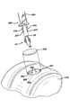
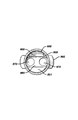
図1および図2を参照すると、本発明の移植片固定装置10の好適な実施の形態の例が示されている。図面から移植片固定装置10が移植部材20を有しているのが分かるであろう。移植部材20は細長い部材であって、好ましくは実質的に円柱状である。移植部材20は、その他の形状、例えば円錐形、ピラミッド形、多角形、立方体、球状などにすることもできる。移植部材20は、先端部22と基端部24とを有する。移植部材20はそれぞれ、外面28と長手方向の軸29とを有する。各移植部材20は、その移植部材20を貫通する長手方向の挿通孔35を有する。移植部材20は、必要に応じて円錐台状の端部(frustoconical end)30および基端面32を有するようにもできる。端面32は平坦であるのが好ましいが、傾斜した面、凹面、および凸面などにしてもよい。端面32には、その中心に挿通孔35と連通した円形の開口36が設けられている。中心開口36の断面は円形が好ましいが、長円形、多角形、正方形、長方形、およびそれらの組合せなどの断面にしてもよい。部材20は、挿通孔35と連通した円形の開口38が設けられた先端面37を有する。必要に応じて設けられる円錐台状端部30とともに示されているように、環状の端面37は開口38の位置でその厚みが最小となるが、端部が円錐台状でない場合はこの厚みは増大する。移植部材20には、その部材20の表面から延出した組織係合縁44を有する一連の突出部40が必要に応じて設けることができる。突出部40を設けなければ、部材20の表面は平坦である。
【0020】
装置10は、両移植部材20を連結する移植片保持部材50を有する。保持部材50はロッド状であって、第1の端部52、第2の端部54、および中央部55を有する。第1の端部52は第1の部材20の基端面32から延び、第2の端部54は他方の部材20の基端面32から延びている。保持部材50の端部54および端部52は、所望に応じて外面28の任意の部分から延出させたり、或いは任意の部分に取り付けてもよい。連結部材50は、頂部55および両脚部56を含む3つの部分に曲げる或いは形成するのが好ましい。頂部55は、脚部56に実質的に垂直である。連結部材50は逆U字形の形状が好ましいが、半円形、円弧、曲線状、三角形、多角形、U字形、およびそれらの組合せなどの形状にすることもできる。連結部材50の端部52および端部54は移植部材20に固着してもよいし、また従来の方法で着脱可能に移植部材20に取着してもよい。連結部材50は硬質であっても軟質であってもよい。連結部材50は、人工組織マトリックスを骨またはその他の体表面の所定の位置に効果的に保持するために十分な表面領域を有する。連結部材50の断面は円形が好ましいが、長円形、多角形、正方形、長方形、およびそれらの組合せなどの断面形状にすることもできる。連結部材50は硬質であっても軟質であってもよく、1つのフィラメント形構造、または相互に連結した複数のフィラメント若しくは部材とすることもできる。
【0021】
図3乃至図8を参照すると、外科手術手順に用いられる本発明の移植片固定装置10の例が示されている。まず、図3を参照すると、本発明の移植片固定装置10を用いて人工組織を含むマトリックスを固定する前に、第1のステップで、例えば膝関節の軟骨下骨などの骨210に2つのボアホール200を穿孔或いはタップする。ボアホール200は円柱状の孔であって、底部208、開いた頂部202、および側壁205を有する。必要に応じてボアホール200を、底部を有しない、すなわち開いた底部を有する貫通した挿通孔にすることもできる。図10に例が示されている器具400を用いて骨にボアホールをタップするのが特に好ましい。この器具400は、当分野では従来から「スラップハンマー(slap hammer)」部と呼ぶ基部を有する。本明細書で用いる用語「タッピング」または「タップ」は、器具400の軸405の先端部415から延出した先端の尖ったプロング420を骨の所定部位に配置し、軸460上において基端部410と基部ストッパー470との間をスライドするハンマーハンドル450(スラップハンマーの)で、器具400の基端部410に打撃を加えて、骨ボアホール200を形成する手順を指す。軸460の先端部465は基端部411に取り付けられている。基部ストッパー470は基端部467に取着されている。ハンマーハンドル450は握り部451、カラー455、および長手方向の挿通孔457を有する。当業者であれば、類似の尖った器具、即ち釘状の先端を有する任意の器具を用いて骨にボアホールをタップすることが可能であることを理解できよう。また、好ましくはないが1回につき1つのボアホールをタップしてもよい。外科医は骨にボアホールを穿孔する場合、従来の任意の外科用穿孔装置を用いることができる。骨210にボアホール200を形成した後、外科医が、図4に示されているように人工組織を含むマトリックス220を骨の表面201に配置する。次に移植片固定装置10を挿入器具250に装着する。図11に例が示されている挿入器具250は、基端部262および先端部264を有する細長いロッドである。ロッド260の先端部264には深さストッパー290が取着されている。深さストッパー290は、ロッド260の長手方向の軸251に垂直に取着された実質的に矩形の部材である。深さストッパー290は底部292を有する。プレート部材290の底部292から先端方向に、離間した平行な一対の固定プロング270が延出している。固定プロング270は実質的にロッド状の部材であって、先端の尖った先端部277および基端部272を有する。プロング270は、第1の部分273および先端部分275を有する。先端部分275は部材20の挿通孔35の中に完全に挿入可能であるが、基部273は挿通孔35の中に挿入されないように、第1の部分273の断面寸法が先端部分275の断面寸法より大きくなっている。器具250はスラップハンマー部を有する。スラップハンマー部は、基端部262から延びた軸300と、軸300において基端部262と基部ストッパー330との間をスライド可能なハンマーハンドル320(スラップハンマー)とからなる。ハンマーハンドル部材320は、握り部325、端部カラー327、および長手方向の挿通孔329を有する。移植片固定装置10は、プロング270の先端部分275が移植部材20の長手方向の挿通孔35内に係合し、先端277が先端面37から突き出るように、移植部材20をプロング270に差し込んでスライドさせ、挿入器具250に取り付ける。次に、図5および図6に示されているように、プロング270に取り付けられた移植部材20をボアホール200の中に挿入するために、器具250を操作して移植片固定装置10をマトリックス220を介して骨210の中に挿入して、部材20をボアホール200に係合させ、保持部材50の組織保持部55がマトリックス220に係合するようにし、マトリックス220が骨210の表面201にしっかりと係合するようにする。所望に応じて、装置10を挿入する前にマトリックス220に孔を形成することもできる。次に、図7に示されているように、挿入器具250を基部方向に移動させて、プロング270を移植部材20の挿通孔から引き抜くと、移植片固定装置10が係合した状態で骨のボアホールに残存するため、マトリックス220が骨210の表面201と係合した状態で維持される。プロング270を引き抜く際に、器具250のスラップハンマー部を利用することができる。図8には、固定装置10が骨210に係合してマトリックス220が骨210の表面201に係合している断面図の例が示されている。
【0022】
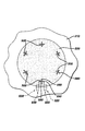
図12には、骨210の表面201に固定されたマトリックス220の例が示されている。マトリックス220には、このマトリックス220を固定するべく本発明の複数の固定装置が配設されている。十分に効果的にマトリックス220を骨表面201に固定するために必要な固定装置10の数、解剖学的位置、および向きは、移植片即ちマトリックスの大きさや種類、組織の種類、患者の年齢、患者の障害の大きさ、固定装置の大きさ、固定装置の材料、修復部位における組織にかかる負荷などによって異なる。
【0023】
当業者であれば、本発明の固定装置の大きさが、固定装置の設計、材料、固定装置の適用例、外科的手順のタイプなどを含む変化する要素によって変化することが理解できるであろう。同様に、固定装置で固定するマトリックスの大きさも変化する。本明細書の一部である図面は、本発明の装置および方法の単なる模式的な例であって、実際には固定装置およびマトリックスの実際の寸法が異なる場合があることを理解されたい。
【0024】
後述する例は、本発明の概念および実施の例を示すものであって本発明を限定するものではない。
【0025】
標準的な無菌外科手術技術を用いる外科手術を行うために、6匹のヒツジを用意した。この無菌外科手術技術には、十分に消毒した器具や装置の使用、従来の麻酔手順およびプロトコルが含まれる。次に外科医が、骨格が成熟した6匹のヒツジのそれぞれにおいて、直径7mmの軟骨障害(軟骨の全厚みに対して)を大腿骨の内側顆の荷重のかかる領域および右後膝(膝)の滑車溝(trochlear groove)に形成した。この障害の形成には、軟骨下骨の露出および軟骨下骨への侵入を防止するための深さストッパーの付いた専用のドリルを用いた。全ての障害のベース面には、細胞遊走が可能となるように専用のマイクロピック装置で微小破壊部を設けた。実験動物をそれぞれ2匹づつの3つのグループに分けた。
【0026】
グループ1は、障害をコラーゲンマトリックスで覆い、本発明の移植片固定装置で固定した。グループ2は、障害をコラーゲンマトリックスで覆い、9−0吸収性Vicryl(商標)縫合糸で固定した(結節縫合技術、1マトリックスに付き約12ストランド)。グループ3は、障害をそのままにしておいた(対照グループ)。所定の後膝における両方の障害は、同じ治療をするか或いは対照とした。
【0027】
グループ1の2匹のヒツジは、障害を形成して微小破壊した後、パンチ器具400を用いて、本発明の1つの移植片固定装置を受容するために必要な2つのボアホールを軟骨下骨に形成した。唯1つのポリジオキサノン装置(先端と先端との距離が4mm)で各マトリックスを固定した。ボアホールを形成するために、パンチ器具を矢状面に向けて障害の中心に配置し、パンチ器具が軟骨下骨の中に数ミリメートル進入するまで、スラップハンマーで打撃を与える即ちタッピングを繰り返した。次に、生理食塩水に浸してある直径7mmの円形のコラーゲンマトリックスを障害に配置し、過剰な生理食塩水を吸い取って乾燥させた。挿入器具250に本発明の移植片固定装置10を装着し、固定装置および挿入器具を矢状面に向けてマトリックスの中心に配置した。次に外科医が、挿入器具の先端をマトリックスに徐々に進入させて、予め形成されたボアホールに導いた。外科医は、挿入器具の先端をボアホールの中に導いた後、ハンマーを用いて挿入器具(および固定装置10の移植部材20)をマトリックスを貫通して軟骨下骨の中に十分に挿入した。挿入器具は、移植部材20が深くまで進入し過ぎるのを防止するべく深さストッパーを有しており、それによって移植部材20がマトリックスを貫通して適切に配置されるようになっている。2つの移植部材間の連結保持部材がコラーゲンマトリックスを押圧し始めると、固定装置が下側の軟骨下骨に確実に固定されたことを意味し、挿入が完了する。所定の後膝における2つの障害をマトリックスおよび固定装置で修復した後、後膝を縫合してヒツジの回復を待った。外科医が本発明の固定装置をマトリックスに固定するのにはわずか1分しかかからなかったが(グループ1)、マトリックスを縫合糸で結節して固定するのには15分もかった(グループ2)。
【0028】
手術の2週間後に、膝関節を検査するために外科的に切開した。関節を肉眼で検査すると、本発明の移植片固定装置によって固定された4つのマトリックスの全てが完全な状態すなわち無傷のままであった。しかしながら、縫合糸のみによって固定された4つ全てのマトリックスは、部分的に無傷の状態であり、平均すると任意のマトリックスにおける縫合の約30%が損傷を受けていた。
【0029】
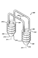
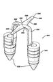
本発明の固定装置の別の実施の形態では、図9に示されているように複数の保持部材が設けられている。装置300は、一対の移植部材310を有する。移植部材310は実質的に円柱状であって、長手方向の軸311、先端部314、および基端部312を有する。それぞれの移植部材310は長手方向の挿通孔320を有する。移植部材310は、円錐台状の先端部分(frustoconical end)330、外面350、およびその外面350から外向きに延出したリッジ355を有する。部材310は、それぞれが第1の端部342および第2の端部344を有する一対の保持部材340によって連結されている。
【0030】
本発明の固定装置の別の実施の形態の例が、図13乃至図17に示されている。移植片固定装置500は移植部材520を有する。移植部材520は細長い部材であって、実質的に円柱の形状が好ましい。部材520は、円錐形、ピラミッド形、多角形、立方体、球形などを含む別の形状にしてもよい。先端部522および基端部524を有する。それぞれの移植部材520は、外面528および長手方向の軸529を有する。各部材520はまた、その各部材520を貫通する長手方向の挿通孔535を有する。移植部材520はまた、随意選択の円錐台状の端部(frustoconical end)530、基端面532を有する。端面532は平坦であるのが好ましいが、傾斜した端面、凹状の端面、または凸状の端面などにしてもよい。それぞれの端面532は、挿通孔535と連通した中心に設けられた円形の開口536を有する。中心開口536は円形の断面形状を有するのが好ましいが、長円形、多角形、正方形、長方形、およびそれらの組合せなどを含むその他の断面形状であってもよい。部材520はまた、挿通孔535と連通した円形の開口538を備えた先端面537を有する。端面537は尖った縁を有するのが好ましいが、丸みを帯びた形状や平坦な形状にしてもよい。随意選択の円錐台状の端部530とともに示されているように、環状の端面537は開口538の位置でその厚みが最小となるが、先端部を円錐台状にしない場合はこの厚みは増大する。しかしながら、好ましくはないが上記したように端面537を様々な幅にしてもよい。一連の組織係合縁544を有する随意選択の突出部540が、部材520の表面528から外向きに延出している。部材520の表面528は、突出部540が存在しない場合は平坦になるため、このような場合には、粗い表面を有するか、或いは円錐形、半球、ロッド、フック、およびそれらの等価物などの従来の様々な突出部を有するようにするのが好ましい。
【0031】
装置500は、移植部材520を連結する移植片保持部材550を有する。保持部材550は、好ましくは長円形の断面を有するバンド状の部材である。保持部材550は、第1の端部552、第2の端部554、および中央部555を有する。第1の端部552は、第1の部材520の基端面532から上方に延出しており、第2の端部554は、他方の部材520の基端面532から上方に延出している。第1の端部552の部分557は表面528の部分539から外向きに延出しており、第2の端部554の部分558も表面528の部分539から外向きに延出している。保持部材550の端部552,554は、要求に応じて、外表面528のいかなる部分から延びていてもよいし、外表面528のいかなる部分に取り付けられていてもよい。連結部材550は、頂部555および脚部556を含む3つの部分に曲げる或いは形成するのが好ましい。頂部555は弧状の部材であって、脚部556は表面532に対して垂直であるのが好ましい。連結部材550は逆U字型の形状が好ましいが、半円形、弧状、曲線、三角形、多角形、V字形、およびそれらの組合せなどを含む別の形状であってもよい。連結部材550の端部552および端部554は、移植部材520に固着してもよいし、例えばボール、ソケットジョイント、プラグジョイントなどの様々な従来の方式で着脱可能に取着してもよい。部材550は硬質であっても、軟質であってもよい。部材550は、人工組織マトリックスを骨或いはその他の体表面の所定の位置に効果的に保持するべく、十分な表面領域を有する。連結部材550は、長円形の断面を有するのが好ましいが、円形、卵形、多角形、正方形、長方形、およびそれらの組合せを含むその他の断面形状にしてもよい。部材550は硬質または軟質であって、1つのフィラメント構造であっても複数の相互接続したフィラメントや部材であってもよい。
【0032】
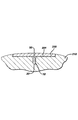
図35および図36には、横方向のウイング部材580を有する移植片固定装置500の実施の形態が示されている。図35を参照すると、装置500は、連結部材(すなわち移植片保持部材)550の中央部555から横方向に延出したウイング部材580を有する。ウイング部材580は好ましくは細長くて、先端部584および基端部582を有する。先端部584から丸いノーズ590が延出している。ノーズ590は、所望に応じて、円錐形およびピラミッド形などの別の幾何学的形状にすることもできる。ウイング部材580は外面586を有する。図35に示されているように、ウイング部材580は円形の断面を有し、最大寸法を有する基端部582から先細になっている。保持部材550の基端部582と頂部555との間に移行部592が存在する。所望に応じて、ウイング部材580の長さに沿って直径を一定とすることもできる。ウイング部材580は、楕円形、正方形、長方形、三角形、多角形、曲線、およびそれらの組合せなどを含む別の断面形状にしてもよい。ウイング部材580の長さは、移植片を効果的に保持するのに十分な長さである。所望に応じて、好ましくはないがウイング部材580を、細長くする代わりにその長さを短かく或いは中間的な長さにすることもできる。同様に、移植片を効果的に保持するべく、ウイング部材580の幅や直径を変更することもできる。保持部材550から横方向に延出した互いに反対向きの2つのウイング部材580を有するのが好ましいが、装置500に設けるウイング部材580を唯1つ或いは複数にしてもよい。図36に例が示されているように、ウイング部材580を有する保持装置500は、骨の中に挿入され、移植マトリックスを固定している。ウイング部材580を有する装置500の移植方法およびステップは、本明細書で例を用いて説明したウイング部材580を含まない装置500の移植方法と実質的に同じである。図36に示されているように、表面586の少なくとも一部が、骨210上のマトリックス220の上面と係合している。
【0033】
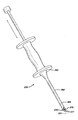
本発明の別の態様は、本発明の固定装置とともに用いると有用な挿入部材(装置)である。図18に示されているように、挿入装置600は、基端部610および先端部620を有する実質的に柱状の部材である。基端部610は平坦な端面612を有する。円錐台状の端部630が、先端部620から先端方向に延出しているが、装置600は別の形状にすることもできる。所望に応じて、先端部620がテーパ状或いは曲線の形状を有するようにもできるが、先端部620から円錐台状の末端部が延出しているのが好ましい。円錐台状の末端部630は、外面632および先端640を有する。部材600はまた、外面650を有する。部材600は、その部材600を長手方向に貫通する挿通孔660を有する。挿通孔660は、この挿通孔660と連通した第1の円形の開口665と、挿通孔660と連通した、先端640に設けられた第2の円形の開口667を有する。挿入部材600を本発明の移植部材と組み合わせて用いて、骨の中にボアホールをタッピングすると同時に骨に移植部材を係合させることによって、固定部材を挿入する前に予めボアホールを形成するステップを省くことができる。
【0034】
図19乃至図21を参照すると、上述した挿入部材600と固定装置500との組合せの例が示されている。初めに、固定部材500を、器具400の軸405の先端部415から延びているプロング700に取り付ける。それぞれのプロング700は、軸405の先端部415から延出した第1の円柱部710を有する。それぞれの円中部710は、基端部711、先端部712、および受容溝715を有する。中央のピン部720が、それぞれの第1の円柱部710の先端部712から延出している。中央のピン部720は、基端部722および先端部724を有する。先端ピン部材730が、中央のピン部720の先端部724から先端方向に延出している。先端ピン部材730は、基端部732および先端部734を有する。
【0035】
所望に応じて、挿入部材600を移植部材520の先端の中に鋳造して或いはその先端に取り付けて、図31および図32に示されているような一体構造としてもよい。さらに、接着、セメンティング、機械的取付け、摩擦ばめ、およびそれらと同等の方法などの従来の方法で移植部材520の先端部に挿入部材600を取り付けることもできる。
【0036】
図33および図34に、上記したようなウイング部材580を有する一体構造の移植装置500と挿入部材600の組合せの例が示されている。ウイング部材580を有するこの組合せ体によって、図34に示されているようにマトリックス220が骨210に固定される。図示されていないが、所望に応じて、ウイング部材580を有する挿入装置500と挿入部材600を分離することもできる。このウイング部材580を有する組合せ体を挿入する方法は、本明細書で説明および例示した方法と実質的に同じである。
【0037】
挿入部材600と本発明の固定部材500などの固定部材との組合せ体を用いて、後述の方法でマトリックスを骨に固定する。まず、固定装置500の移植部材520を器具400のプロング700に取り付ける。この時、脚部材556が、第1の部分710(図21を参照)に設けられた溝715に少なくとも部分的に係合し、移植部材520の先端部からピン部材730が突出して、ピン部材730の中間部分720が移植部材520の挿通孔535に係合するようにする。次に、尖った穿孔先端部734が挿入部材660の先端640から突出して、ピン部材730が挿通孔660に係合するように、挿入部材600をピン部材730に取り付ける。次に、固定装置500および挿入部材600からなる組立体と器具400とを骨210に配置された組織マトリックス220上に配置する。次に、穿孔先端部を押圧してマトリックス220を貫通して骨210の表面211に接触するようにする。器具400のスラップハンマーを用いて穿孔先端部734を骨に進入させ、挿入部材600および移植部材520を骨210の中に挿入するとともに、骨にボアホール200を形成する。次に、器具400を基部方向に引き戻して、プロング700の中間部720を移植部材520から、ピン部材730を挿入部材600から引き抜き、挿入部材600および移植部材520が骨に固定した状態で残存するようにする(図20を参照)。従って、上記したように挿入部材600および固定装置500が骨に固定されると同時に骨にボアホールが形成される1回のステップで、骨210へのマトリックス220の固定が完了する。
【0038】
本発明の固定装置を挿入する際、従来の遠隔映像化外科手術手順(remote visualization surgical procedure)を用いるのが特に好ましい。例えば、関節や体腔を吸引しながら、トローカルカニューレを介して関節や体腔の中に検査鏡を挿入する。
【0039】
挿入部材600は、通常は丈夫で硬質の生体吸収性材料からなるため、破壊されたり損傷を受けたりすることなく骨の中に挿入することができる。挿入部材600を形成するために用いることができる材料の種類は、ポリ乳酸、ポリグルコール酸、リン酸3カルシウム、リン酸カルシウム、リン酸4カルシウム、ヒドロキシアパタイト、任意のコポリマー、およびそれらの合成物や混合物が含まれる。好ましくはないが、従来の生体適合性金属で挿入部材を形成することもできる。このような生体適合性金属は、生体吸収性でも生体分解性でもないチタン、ステンレス鋼、セラミック、ニチノール(Nitinol)、およびそれらの等価物などが含まれる。挿入部材600は、移植部材520を保護しながらボアホール200の形成を助ける。
【0040】
図22および図23には、本発明の器具400のための使い捨て先端部組立体800の例が示されている。使い捨て組立体800を用いる場合は、器具400の軸405の先端部415にねじ418を設けるのが好ましい。ただし、ねじの代わりに、例えば、差し込み型据付具、固定レバーとタブ、オスメス型係合部などの従来の着脱可能な据付具を用いてもよい。図22乃至図25に示されているように、組立体800は、基端部811および先端部817を有するハウジング810からなる。ハウジング810は、その内部に中空のキャビティ815を有する。キャビティ815は、基端部の開口812および先端部の開口820と連通している。部材810は外面822を有する。外面822は、ハウジング810の保持および回転が容易になるように刻みを設けるのが好ましい。ハウジング810は、さらに先端面825を有する。外面822は、先端面825に向かって先細になったテーパ部823を有する。キャビティ815の内面818にはねじ819が設けられている。組立体800はまた、挿入ピン部材830を有する。それぞれの挿入ピン部材830は、基端部831に取り付けられた基端部ディスク部材832、軸部834、および先端835を有する。部材810の内部の各開口820は、環状の溝840で囲まれている。組立体800は、後述の方式で器具400の先端部415に取り付けられる。ピン830をキャビティ815の中に挿入して開口820を貫通させ、軸834および尖った先端835が端面825から突出し、ディスク部材832が環状の溝840の中に受容されるようにする。次に、ディスク部材832の基端面833が先端部415の端面416と接触するまでねじ819にねじ418をねじ込んで、ハウジング810を先端部415に固定する。外科手順に用いた後、組立体800を取り外して廃棄する。新規の外科手順の度に、新しい消毒した組立体800を消毒した清潔な器具400に取り付ける。
【0041】
図26乃至図30を参照すると、挿入器具250に取り付ける使い捨ての組立体900の例が示されている。挿入部材250は、端面265およびねじ266を備えた先端264を有する。組立体900はハウジング950を有する。ハウジング950は、基端部952、先端部956、および外面954を有する。プレート部材960が先端部956から延出している。プレート部材960は先端面962を有する。外面954は、プレート部材960に向かって先細になったローレット切りテーパ先端部957を随意選択で有する。ハウジング950は内部にキャビティ955を有する。ハウジング950は、キャビティ955と連通した基部の開口951と、同様にキャビティ955と連通した先端部の開口970とを有する。ハウジング950は、内面958に形成された雌ねじ959を有する。先端部956のハウジング950内には嵌込み溝980が設けられている。組立体900は、後述の方式で器具250の先端部264に取り付けられる。基部部材922が溝980と係合するように、ピン910をキャビティ950から開口970の中に挿入して、ピン910の部分920および部分930が開口970から延出するようにする。部分920は溝925を有する。次に、先端部264をハウジング950に挿入し、ねじ266とハウジング950の雌ねじ959を螺合させる。先端部264の先端面265が部材922の上面923と係合するまでハウジングをねじ込む。外科手順の後、組立体900を器具250から取り外して廃棄する。新規の外科手順の度に、新しい消毒した組立体900を消毒した清潔な器具250に取り付ける。
【0042】
本発明の固定装置、本発明の固定装置と挿入部材との組合せ体、並びに本発明のこのような装置および組合せ体の使用方法には多くの利点がある。その1つは、人工組織またはその他の組織のマトリックスを迅速かつ簡便に固定する方法を提供することである。固定装置および組合せ体は結節縫合する必要がないため、最小の外科的切開が求められる関節鏡外科手順に用いて、患者の病的状態を著しく改善することができる。さらに、固定装置および組合せ体は、周囲の組織に針を通さなければならない(それによって損傷を与える)従来の縫合を用いる軟骨障害マトリックスの従来の固定法とは異なり、周囲の正常な軟骨組織に損傷を与えることのない優れたマトリックスの固定を実証した。
【0043】
詳細な実施の形態を用いて本発明を説明してきたが、当業者であれば、請求した発明の範囲および概念から逸脱することなく、形態および細部における様々な変更が可能であることを理解できるであろう。
【0044】
本発明の実施態様は以下の通りである。
(A)固定装置と一対の挿入部材の組合せ体を含む移植片固定装置であって、
前記固定装置が、
第1の移植部材であって、長手方向の軸と、基端部と、先端部と、外面と、前記第1の移植部材を貫通する長手方向の挿通孔とを有する、前記第1の移植部材と、
第2の移植部材であって、長手方向の軸と、基端部と、先端部と、外面と、前記第2の移植部材を貫通する長手方向の挿通孔とを有する、前記第2の移植部材と、
前記第1の移植部材と前記第2の移植部材とを連結する連結部材であって、中央部と、前記第1の移植部材から延出した第1の端部と、前記第2の移植部材から延出した第2の端部を有する、前記連結部材と、
前記連結部材から横方向に延出した少なくとも1つのウイング部材とを含み、
前記一対の挿入部材のそれぞれが、
基端部と、テーパ状の先端部と、長手方向に貫通する挿通孔とを有する部材を含み、
前記各移植部材の前記先端部が、前記挿入部材の前記基端部と係合していることを特徴とする移植片固定装置。
(1)前記移植部材が、その外面から延出した一連のリッジを有することを特徴とする実施態様(A)に記載の装置。
(2)前記連結部材が、中央部およびロッド部材を有する構造を含み、前記ロッド部材が前記移植部材の長手方向の軸と実質的に平行になっており、前記中央部が前記ロッド部材と実質的に垂直になっていることを特徴とする実施態様(A)に記載の装置。
(3)前記連結部材が半円形の形状を有することを特徴とする実施態様(A)に記載の装置。
(4)前記第1の移植部材の前記先端部および前記第2の移植部材の前記先端部から延出した円錐台状の先端部をさらに含むことを特徴とする実施態様(A)に記載の装置。
(5)前記移植部材が円柱状の構造を有することを特徴とする実施態様(A)に記載の装置。
【0045】
(6)前記挿入部材が、ポリ乳酸、ポリグルコール酸、リン酸3カルシウム、リン酸カルシウム、リン酸4カルシウム、ヒドロキシアパタイト、コポリマー、およびそれらの合成物や混合物からなる群から選択される生体吸収性材料を含むことを特徴とする実施態様(A)に記載の装置。
(7)前記挿入部材が、チタン、ステンレス鋼、セラミック、およびニチノール(Nitinol)からなる群から選択される生体適合性材料を含むことを特徴とする実施態様(A)に記載の装置。
(8)前記固定装置が生体吸収性ポリマーを含むことを特徴とする実施態様(A)に記載の装置。
(9)前記固定装置が、前記連結部材から互いに反対向きに延びた2つのウイング部材を含むことを特徴とする実施態様(A)に記載の装置。
(10)前記挿入部材が、先端方向に延出した円錐台状の先端を有する円柱状の形状であることを特徴とする実施態様(A)に記載の装置。
【0046】
(B)固定装置であって、
第1の移植部材であって、長手方向の軸と、基端部と、先端部と、外面と、前記第1の移植部材を貫通する長手方向の挿通孔とを有する、前記第1の移植部材と、
第2の移植部材であって、長手方向の軸と、基端部と、先端部と、外面と、前記第2の移植部材を貫通する長手方向の挿通孔とを有する、前記第2の移植部材と、
前記第1の移植部材と前記第2の移植部材とを連結する連結部材であって、中央部と、前記第1の移植部材から延出した第1の端部と、前記第2の移植部材から延出した第2の端部とを有する、前記連結部材と、
前記連結部材から横方向に延出した少なくとも1つのウイング部材とを含むことを特徴とする固定装置。
(11)前記移植部材が、その外面から延出した一連のリッジを有することを特徴とする実施態様(B)に記載の装置。
(12)前記連結部材が、中央部およびロッド部材を有する構造を含み、前記ロッド部材が前記移植部材の長手方向の軸と実質的に平行になっており、前記中央部が前記ロッド部材と実質的に垂直になっていることを特徴とする実施態様(B)に記載の装置。
(13)前記連結部材が半円形の形状であることを特徴とする実施態様(B)に記載の装置。
(14)前記第1の移植部材の前記先端部および前記第2の移植部材の前記先端部から延出した円錐台状の先端部をさらに含むことを特徴とする実施態様(B)に記載の装置。
(15)前記移植部材が円柱状の構造を有することを特徴とする実施態様(B)に記載の装置。
【0047】
(16)前記固定装置が生体吸収性ポリマーを含むことを特徴とする実施態様(B)に記載の装置。
(17)前記固定装置が、前記連結部材から互いに反対向きに延出した2つのウイング部材を含むことを特徴とする実施態様(B)に記載の装置。
【0048】
【発明の効果】
移植した組織が患者の体内で成長を続けて組織が再生されるように、組織工学的に作製された人工組織のマトリックスを骨またはその他の固着部位に効果的に固定する組合せ移植片固定装置を提供できる。
【図面の簡単な説明】
【図1】本発明の移植片固定装置の斜視図である。
【図2】図1の線2−2に沿った移植片固定装置の断面図である。
【図3】本発明の移植片固定装置を用いたマトリックスを骨に固定する外科手順の例を示す図である。
【図4】本発明の移植片固定装置を用いたマトリックスを骨に固定する外科手順の例を示す図である。
【図5】本発明の移植片固定装置を用いたマトリックスを骨に固定する外科手順の例を示す図である。
【図6】本発明の移植片固定装置を用いたマトリックスを骨に固定する外科手順の例を示す図である。
【図7】骨に形成されたボアホールに移植部材を移植した後の本発明の移植片固定装置が骨にマトリックスを確実に固定している状態を示す図である。
【図8】図7の線8−8に沿った骨に移植された移植片固定装置の断面図である。
【図9】2つの連結部材を有する本発明の移植片固定装置の代替の実施の形態を示す図である。
【図10】本発明の移植片固定装置の移植部材を挿入するボアホールを骨に形成するのに有用な器具の斜視図である。
【図11】本発明の装置を骨に形成されたボアホールに移植するのに有用な器具の斜視図である。
【図12】本発明の幾つかの移植片固定装置で骨に固定された人工組織マトリックスを示す図である。
【図13】本発明の移植片固定装置の代替の実施の形態の斜視図である。
【図14】図13の移植片固定装置の側面図である。
【図15】図14の移植片固定装置の端面図である。
【図16】図14の線16−16に沿った移植片固定装置の断面図である。
【図17】図14の線17−17に沿った移植片固定装置の組織保持部材の断面図である。
【図18】本発明の移植片固定装置の挿入に有用な挿入部材の斜視図である。
【図19】挿入器具、移植片固定装置、および2つの挿入部材を示す組立分解図である。
【図20】挿入器具を取り外す前の挿入器具の先端部、移植片固定装置、骨に係合している挿入部材の側面図である。
【図21】図20の線21−21に沿った断面図であって、挿入器具のプロング、およびそのプロングの長手方向の溝に係合した挿入部材のある部分を示している。
【図22】本発明の挿入器具の先端部の組立分解図であって、本発明の固定装置を受容する骨に形成されたボアホールを形成するための、端部部材およびピンを有する着脱可能な先端部組立体の例を示している。
【図23】図22の面23に沿った組立体の断面図である。
【図24】完全に組み立てられて使用可能状態の図22の組立体端部の斜視図である。
【図25】図24の面25に沿った端部組立体の断面図である。
【図26】本発明の挿入器具の組立分解図であって、この挿入器具は、端部組立体部品および2つのピンを含む取り外し可能な先端部を有し、本発明の移植片保持部材を骨に形成されたボアホールに挿入するのに有用であり、挿入部材とともに用いて、予め骨にボアホールを形成しなくても固定装置を骨に直接挿入することができる。
【図27】図26の端部組立体部品の断面図である。
【図28】端部組立体部品およびプロングが組み立てられて固定された、図26の挿入器具の先端部の斜視図である。
【図29】図28の面29に沿った挿入器具の先端部の断面図である。
【図30】図29の線30−30に沿った挿入器具の断面図である。
【図31】各移植部材の先端部の中に鋳造された挿入部材を有する本発明の固定装置の例を示す図である。
【図32】図31の固定装置の断面図である。
【図33】横方向に延出したウイング部材を有する本発明の移植片固定装置の代替の実施の形態の斜視図である。
【図34】図33の移植片固定装置を幾つか用いて骨に固定されたマトリックスを示す図である。
【図35】横方向に延出したウイング部材を有する本発明の移植片固定装置の別の代替の実施の形態の斜視図である。
【図36】図35の移植片固定装置を幾つか用いて骨に固定されたマトリックスを示す図である。
【符号の説明】
500 固定装置
520 移植部材
550 連結部材
600 挿入部材[0001]
BACKGROUND OF THE INVENTION
This application is a continuation-in-part of U.S. Patent Application No. 09 / 360,367, filed July 23, 1999, assigned to the present applicant, March 2000 assigned to the present applicant. This is a continuation-in-part of US patent co-pending application 09 / 535,183, filed 27 days ago. Reference to these patents is also incorporated herein. The present invention relates to a surgical fixation device and to a surgical fixation device for fixing a tissue graft to bone.
[0002]
[Prior art]
Medical technology related to tissue engineering is advancing rapidly. In particular, it is known to collect cells from the human body such as collecting chondrocytes and fibrochondrocytes from the knee joint. These autologous cells are cultured on a bioabsorbable matrix in a laboratory environment. Usually, the matrix is shaped substantially similar to the shape of the tissue portion to be replaced. When cultured in a suitable medium for a sufficient amount of time under appropriate environmental conditions, the harvested cells grow on the matrix and form an implant of substantially the same physical shape as the tissue piece that replaces the patient. Such tissue engineered structures consisting of cells on a matrix (or alternatively consisting solely of a matrix) can be transformed into bone using conventional surgical fixation methods including suturing, periosteal coating, and fibrin adhesion. Fix to the site.
[0003]
There are many benefits of tissue engineering, for example, one of which is to replace cartilage with live cartilage tissue. Furthermore, since cartilage tissue grown in vitro is identical to the patient's autologous cartilage, the potential for transplant rejection is minimized.
[0004]
Existing matrix fixation devices fully fulfill their intended purpose, but have some disadvantages in use. First, existing fixation devices are general purpose fixation devices that can be used in various surgical procedures and are not specifically designed to fix the matrix to bone or soft tissue. Another disadvantage includes that many of these existing devices are difficult to use in minimally invasive arthroscopic procedures. Another disadvantage is the difficulty and surgical injuries in harvesting periosteum for use as a periosteal valve, the significant patient failure rate associated with such harvesting, this There are difficulties in suturing such a thin soft material to the surrounding tissue.
[0005]
[Problems to be solved by the invention]
Therefore, a tissue-engineered tissue (hereinafter referred to as artificial tissue) matrix is used as a bone or tissue so that the transplanted tissue continues to grow and regenerate in the patient's body. There is a need in the art for new anchoring devices that effectively anchor to other anchoring sites.
[0006]
Accordingly, it is an object of the present invention to provide a fixation device that effectively anchors the matrix to a bone or other anchoring site that allows the matrix of the artificial tissue to remain at the transplantation site until the transplanted tissue has grown and regenerated Is to provide.
[0007]
Another object of the present invention is to provide a fixation device for fixing a matrix to a bone site that can be easily attached in an arthroscopic or open procedure.
[0008]
It is a further object of the present invention to provide an anchoring device for anchoring a matrix to a bone site that does not require sutures or sutures to be tied.
[0009]
It is a further object of the present invention to provide a surgical method for securing a matrix using such a device in place within a patient's body.
[0010]
[Means for Solving the Problems]
Accordingly, a graft fixation device is disclosed. The graft fixation device has a first graft member and a second graft member. These members are elongated and preferably have a cylindrical shape. These implants have a distal end, a proximal end, and a longitudinal axis. Each implant has a longitudinal insertion hole that extends through its entire length. The implant member has an outer surface. Both implants are connected to each other by a rod member having a first end, a second end, and a central portion. The first end of the rod member extends from the proximal end of the first graft member, and the second end of the rod member extends from the proximal end of the second graft member. The rod member is preferably relatively rigid and can have various shapes, such as an inverted U shape. However, the rod member may be soft. The rod member maintains both implant members in a relatively constant position relative to each other. The central portion of the rod member is designed to engage a portion of the artificial tissue matrix to be implanted. In a preferred embodiment, the implant has a series of ridges extending outwardly from the outer surface of the implant. This series of ridges prevents the implant from escaping from the bone site or other fixation site after the implant is implanted in a pre-formed borehole.
[0011]
Another aspect of the present invention is a method of fixing a matrix containing artificial tissue to bone using the graft fixation device of the present invention.
[0012]
A further aspect of the present invention is a combined graft fixation device that combines a fixation device and an insertion device. The fixation device has a first implant. The graft member has a longitudinal axis, a proximal end, a distal end, an outer surface, and a longitudinal insertion hole that passes through the graft member. The fixation device has a second implant. The second transplant member has a longitudinal axis, a proximal end, a distal end, an outer surface, and a longitudinal insertion hole that penetrates the transplant member. Each implant has a proximal end annular surface surrounding the longitudinal insertion hole. A connecting member connects the first and second transplant members. The connecting member has a central portion, a first end extending from the first graft member, and a second end extending from the second graft member. Each of the pair of insertion devices has a proximal end portion, a tapered distal end portion, and a longitudinal insertion hole penetrating the insertion device. The distal end of each implant is engaged with the proximal end of the insertion device. If necessary, the insertion device may be attached to the distal end of the transplant member.
[0013]
A further aspect of the invention is a graft fixation device. The graft fixation device has a first graft member and a second graft member. These members are elongated and preferably have a cylindrical shape. These members have a distal end, a proximal end, and a longitudinal axis. Each implant has a longitudinal insertion hole that extends through its entire length. The implant member has an outer surface. Both implants are connected to each other by a rod member having a first end, a second end, and a central portion. The first end of the rod member extends from the proximal end of the first graft member, and the second end of the rod member extends from the proximal end of the second graft member. The rod member is preferably relatively rigid and can have various shapes, such as an inverted U shape. However, the rod member may be soft. The rod member maintains both implant members in a relatively constant position relative to each other. At least one wing member extends outwardly from the rod member. The central portion of the rod member is designed to engage the artificial tissue matrix to be implanted. This engagement is facilitated by the wing member. In a preferred embodiment, the implant has a series of ridges extending outwardly from the outer surface of the implant. This series of ridges prevents the implant from escaping from the bone site or other fixation site after the implant is implanted in a pre-formed borehole.
[0014]
A further aspect of the invention is a method of using the graft fixation device described above having a laterally extended wing member for fixing a matrix containing artificial tissue to bone.
[0015]
A further aspect of the invention is a combination graft fixation device that combines a fixation device and an insertion device. The fixation device has a first implant. The graft member has a longitudinal axis, a proximal end, a distal end, an outer surface, and a longitudinal insertion hole through the graft member. The fixation device has a second implant. The second transplant member has a longitudinal axis, a proximal end, a distal end, an outer surface, and a longitudinal insertion hole that penetrates the transplant member. Each implant has a base annular surface that surrounds the longitudinal insertion hole. A connecting rod member connects the first graft member and the second graft member. The connecting rod member has a central portion, a first end extending from the first graft member, and a second end extending from the second graft member. At least one wing member extends laterally outwardly from the coupling member. Each of the pair of insertion devices has a proximal end portion, a tapered distal end portion, and a longitudinal insertion hole penetrating the insertion device. The distal end of each implant is engaged with the proximal end of the insertion device. If necessary, the insertion device may be attached to the distal end of the transplant member.
[0016]
A further aspect of the invention is a method of using a combination graft fixation device as described above having a laterally extended wing member for fixing a matrix containing artificial tissue to bone.
[0017]
DETAILED DESCRIPTION OF THE INVENTION
The above and other features and advantages of the present invention will become more apparent from the following description and accompanying drawings.
[0018]
The graft fixation device of the present invention can be formed from conventional biocompatible materials including absorbable and non-absorbable materials as well as biodegradable materials. Non-absorbable materials that can be used include stainless steel, polyethylene, Teflon, Nitinol, non-absorbable polymers, other biocompatible metals, ceramics, and combinations thereof. included. Absorbable materials that can be used in the manufacture of the graft fixation device of the present invention include conventional bioresorbable or bioresorbable materials well known in the art that are usually easy to injection mold and machine. material). Bioabsorbable and bioresorbable materials include polylactic acid, polydioxanone, polycaprolactone, polyglycolic acid, polygalactanic acid, and other known biocompatible bioabsorbables And bioresorbable polymers, ceramics, composites, combinations thereof, and the like and equivalents.
[0019]
Referring to FIGS. 1 and 2, an example of a preferred embodiment of the
[0020]
The
[0021]
With reference to FIGS. 3-8, there is shown an example of a
[0022]
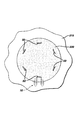
In FIG. 12, an example of a
[0023]
One skilled in the art will appreciate that the size of the fixation device of the present invention will vary depending on changing factors including fixation device design, materials, fixation device application, type of surgical procedure, etc. . Similarly, the size of the matrix fixed by the fixing device also changes. It should be understood that the drawings that are part of this specification are merely schematic examples of the apparatus and method of the present invention, and in fact the actual dimensions of the fixation device and the matrix may vary.
[0024]
The examples described below are merely examples of the concept and implementation of the present invention, and do not limit the present invention.
[0025]
Six sheep were prepared for surgery using standard aseptic surgical techniques. This aseptic surgical technique includes the use of fully disinfected instruments and devices, conventional anesthesia procedures and protocols. The surgeon then performed a 7 mm diameter cartilage lesion (relative to the total thickness of the cartilage) in each of the six skeletal mature sheep in the loaded area of the femoral medial condyle and the right hind knee (knee). Formed into a trochlear groove. A special drill with a depth stopper to prevent subchondral bone exposure and penetration into the subchondral bone was used to create this lesion. On the base surface of all obstacles, a microdestructor was provided with a dedicated micropic device so that cell migration was possible. The experimental animals were divided into 3 groups of 2 animals each.
[0026]
[0027]
Two sheep in
[0028]
Two weeks after surgery, a surgical incision was made to examine the knee joint. When the joint was examined with the naked eye, all four matrices fixed by the graft fixation device of the present invention remained intact or intact. However, all four matrices secured only by sutures were partially intact, and on average about 30% of the sutures in any matrix were damaged.
[0029]
In another embodiment of the fixing device of the present invention, a plurality of holding members are provided as shown in FIG. The
[0030]
An example of another embodiment of the fixing device of the present invention is shown in FIGS. The
[0031]
The
[0032]
35 and 36 illustrate an embodiment of an
[0033]
Another aspect of the present invention is an insertion member (device) useful when used with the fixation device of the present invention. As shown in FIG. 18, the
[0034]
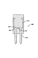
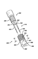
Referring to FIGS. 19 to 21, an example of a combination of the above-described
[0035]
If desired, the
[0036]
FIG. 33 and FIG. 34 show an example of a combination of a single-
[0037]
Using the combination of the
[0038]
It is particularly preferred to use a conventional remote visualization surgical procedure when inserting the fixation device of the present invention. For example, while aspirating a joint or a body cavity, an inspection microscope is inserted into the joint or body cavity via a toroidal cannula.
[0039]
Since the
[0040]
22 and 23 show an example of a
[0041]
Referring to FIGS. 26-30, an example of a
[0042]
There are many advantages to the fixation device of the present invention, the combination of the fixation device of the present invention and the insertion member, and the use of such a device and combination of the present invention. One is to provide a quick and convenient way to fix artificial or other tissue matrices. Because the fixation device and combination do not need to be sutured, it can be used in arthroscopic surgical procedures that require a minimal surgical incision to significantly improve the patient's morbidity. In addition, the fixation device and combination, unlike conventional fixation methods for cartilage damage matrices that use conventional sutures that have to penetrate (and thereby damage) the surrounding tissue, Demonstrated excellent matrix fixation without damage.
[0043]
While the invention has been described in terms of detailed embodiments, those skilled in the art will recognize that various changes in form and detail are possible without departing from the scope and concept of the claimed invention. Will.
[0044]
Embodiments of the present invention are as follows.
(A) A graft fixation device including a combination of a fixation device and a pair of insertion members,
The fixing device is
A first graft member, the first graft having a longitudinal axis, a proximal end, a distal end, an outer surface, and a longitudinal insertion hole penetrating the first graft member. Members,
A second transplantation member, comprising: a longitudinal axis, a proximal end, a distal end, an outer surface, and a longitudinal insertion hole penetrating the second transplantation member. Members,
A connecting member for connecting the first transplant member and the second transplant member, a central portion, a first end extending from the first transplant member, and the second transplant member The connecting member having a second end extending from
And at least one wing member extending laterally from the connecting member,
Each of the pair of insertion members is
Including a member having a proximal end portion, a tapered distal end portion, and an insertion hole penetrating in the longitudinal direction;
The graft fixing device, wherein the distal end portion of each transplant member is engaged with the proximal end portion of the insertion member.
(1) The transplant member has a series of ridges extending from the outer surface thereof.Embodiment (A)The device described in 1.
(2) The connection member includes a structure having a central portion and a rod member, the rod member is substantially parallel to a longitudinal axis of the transplant member, and the central portion is substantially parallel to the rod member. Characterized by verticalEmbodiment (A)The device described in 1.
(3) The connecting member has a semicircular shape.Embodiment (A)The device described in 1.
(4) A cone extending from the tip of the first transplant member and the tip of the second transplant memberStandFurther comprising a tip of a shapeEmbodiment (A)The device described in 1.
(5) The transplant member has a cylindrical structure.Embodiment (A)The device described in 1.
[0045]
(6) The bioabsorbable material in which the insertion member is selected from the group consisting of polylactic acid, polyglycolic acid, tricalcium phosphate, calcium phosphate, tetracalcium phosphate, hydroxyapatite, copolymer, and a composite or mixture thereof. It is characterized by includingEmbodiment (A)The device described in 1.
(7) The insertion member includes a biocompatible material selected from the group consisting of titanium, stainless steel, ceramic, and Nitinol.Embodiment (A)The device described in 1.
(8) The fixing device includes a bioabsorbable polymer.Embodiment (A)The device described in 1.
(9) The fixing device includes two wing members extending in opposite directions from the connecting member.Embodiment (A)The device described in 1.
(10) The insertion member is a cone extending in the distal direction.StandIt is characterized by a cylindrical shape having a shape-like tipEmbodiment (A)The device described in 1.
[0046]
(B) a fixing device,
A first graft member, the first graft having a longitudinal axis, a proximal end, a distal end, an outer surface, and a longitudinal insertion hole penetrating the first graft member. Members,
A second transplantation member, comprising: a longitudinal axis, a proximal end, a distal end, an outer surface, and a longitudinal insertion hole penetrating the second transplantation member. Members,
A connecting member for connecting the first transplant member and the second transplant member, a central portion, a first end extending from the first transplant member, and the second transplant member A second end extending from the connecting member;
And a fixing device including at least one wing member extending laterally from the connecting member.
(11) The graft member has a series of ridges extending from the outer surface thereof.Embodiment (B)The device described in 1.
(12) The connecting member includes a structure having a central portion and a rod member, the rod member is substantially parallel to a longitudinal axis of the transplant member, and the central portion is substantially parallel to the rod member. Characterized by verticalEmbodiment (B)The device described in 1.
(13) The connecting member has a semicircular shape.Embodiment (B)The device described in 1.
(14) A cone extending from the distal end portion of the first transplant member and the distal end portion of the second transplant memberStandFurther comprising a tip of a shapeEmbodiment (B)The device described in 1.
(15) The transplant member has a cylindrical structure.Embodiment (B)The device described in 1.
[0047]
(16) The fixing device includes a bioabsorbable polymer.Embodiment (B)The device described in 1.
(17) The fixing device includes two wing members extending in opposite directions from the connecting member.Embodiment (B)The device described in 1.
[0048]
【The invention's effect】
A combination graft fixation device that effectively fixes a tissue engineered artificial tissue matrix to bone or other fixation sites so that the transplanted tissue continues to grow and regenerate in the patient's body. Can be provided.
[Brief description of the drawings]
FIG. 1 is a perspective view of a graft fixation device of the present invention.
2 is a cross-sectional view of the graft fixation device taken along line 2-2 of FIG.
FIG. 3 is a diagram showing an example of a surgical procedure for fixing a matrix to bone using the graft fixing device of the present invention.
FIG. 4 is a diagram showing an example of a surgical procedure for fixing a matrix to bone using the graft fixing device of the present invention.
FIG. 5 is a diagram showing an example of a surgical procedure for fixing a matrix to bone using the graft fixing device of the present invention.
FIG. 6 is a diagram showing an example of a surgical procedure for fixing a matrix to a bone using the graft fixing device of the present invention.
FIG. 7 is a view showing a state in which the graft fixing device of the present invention after the graft member is implanted into the bore hole formed in the bone securely fixes the matrix to the bone.
8 is a cross-sectional view of a graft fixation device implanted in bone along line 8-8 in FIG.
FIG. 9 shows an alternative embodiment of the graft fixation device of the present invention having two connecting members.
FIG. 10 is a perspective view of an instrument useful for forming a borehole in a bone for inserting an implant member of the graft fixation device of the present invention.
FIG. 11 is a perspective view of an instrument useful for implanting the device of the present invention into a borehole formed in bone.
FIG. 12 shows an artificial tissue matrix secured to bone with several implant fixation devices of the present invention.
FIG. 13 is a perspective view of an alternative embodiment of the graft fixation device of the present invention.
14 is a side view of the graft fixation device of FIG. 13. FIG.
FIG. 15 is an end view of the graft fixation device of FIG.
16 is a cross-sectional view of the graft fixation device taken along line 16-16 of FIG.
17 is a cross-sectional view of the tissue retaining member of the graft fixation device taken along line 17-17 of FIG.
FIG. 18 is a perspective view of an insertion member useful for insertion of the graft fixation device of the present invention.
FIG. 19 is an exploded view showing the insertion instrument, graft fixation device, and two insertion members.
FIG. 20 is a side view of the distal end of the insertion instrument, graft fixation device, and insertion member engaging the bone prior to removal of the insertion instrument.
FIG. 21 is a cross-sectional view taken along line 21-21 of FIG. 20, showing the prong of the insertion instrument and a portion of the insertion member engaged in the longitudinal groove of the prong.
FIG. 22 is an exploded view of the distal end of the insertion tool of the present invention, detachable with end members and pins for forming a bore hole formed in the bone that receives the fixation device of the present invention. An example of a tip assembly is shown.
23 is a cross-sectional view of the assembly along
24 is a perspective view of the end of the assembly of FIG. 22 fully assembled and ready for use.
25 is a cross-sectional view of the end assembly along
FIG. 26 is an exploded view of the insertion tool of the present invention, the insertion tool having a removable tip including an end assembly component and two pins, and the graft holding member of the present invention. It is useful for insertion into a borehole formed in a bone, and can be used together with an insertion member to directly insert a fixation device into a bone without forming a borehole in the bone in advance.
27 is a cross-sectional view of the end assembly component of FIG. 26. FIG.
28 is a perspective view of the distal end of the insertion instrument of FIG. 26 with the end assembly parts and prongs assembled and secured.
FIG. 29 is a cross-sectional view of the distal end of the insertion tool taken along
30 is a cross-sectional view of the insertion instrument taken along line 30-30 of FIG. 29. FIG.
FIG. 31 is a view showing an example of the fixing device of the present invention having an insertion member cast in the distal end portion of each transplant member.
32 is a cross-sectional view of the fixing device of FIG. 31. FIG.
FIG. 33 is a perspective view of an alternative embodiment of the graft fixation device of the present invention having laterally extending wing members.
34 shows a matrix secured to bone using some of the graft fixation devices of FIG. 33. FIG.
FIG. 35 is a perspective view of another alternative embodiment of the graft fixation device of the present invention having a laterally extending wing member.
36 shows a matrix secured to bone using some of the graft fixation devices of FIG. 35. FIG.
[Explanation of symbols]
500 Fixing device
520 Implant
550 connecting member
600 Insertion member
Claims (17)
I.前記固定装置が、
第1の移植部材であって、長手方向の軸と、基端部と、先端部と、外面と、前記第1の移植部材を貫通する長手方向の挿通孔とを有する、前記第1の移植部材と、
第2の移植部材であって、長手方向の軸と、基端部と、先端部と、外面と、前記第2の移植部材を貫通する長手方向の挿通孔とを有する、前記第2の移植部材と、
前記第1の移植部材と前記第2の移植部材とを連結する連結部材であって、中央部と、前記第1の移植部材から延出した第1の端部と、前記第2の移植部材から延出した第2の端部とを有する、前記連結部材と、
前記連結部材から横方向に延出した少なくとも1つのウイング部材と、
を含み、
前記ウイング部材は、基端部および先端部を有し、当該ウイング部材の前記基端部が前記連結部材に結合しており、前記ウイング部材は、当該ウイング部材の前記基端部から前記先端部へと延びる細長い形状を有しており、
II.前記一対の挿入部材のそれぞれが、
基端部と、テーパ状の先端部と、長手方向に貫通する挿通孔とを有する部材、
を含み、
前記各移植部材の前記先端部が、前記挿入部材の前記基端部と係合している、移植片固定装置。A graft fixation device including a combination of a fixation device and a pair of insertion members,
I. The fixing device is
A first graft member, the first graft having a longitudinal axis, a proximal end, a distal end, an outer surface, and a longitudinal insertion hole penetrating the first graft member. Members,
A second transplantation member, comprising: a longitudinal axis, a proximal end, a distal end, an outer surface, and a longitudinal insertion hole penetrating the second transplantation member. Members,
A connecting member for connecting the first transplant member and the second transplant member, a central portion, a first end extending from the first transplant member, and the second transplant member A second end extending from the connecting member;
At least one wing member extending laterally from the connecting member;
Including
The wing member has a proximal end portion and a distal end portion, and the proximal end portion of the wing member is coupled to the connecting member, and the wing member extends from the proximal end portion of the wing member to the distal end portion. Has an elongated shape extending to
II. Each of the pair of insertion members is
A member having a base end, a tapered tip, and an insertion hole penetrating in the longitudinal direction;
Including
The graft fixing device, wherein the distal end portion of each transplant member is engaged with the proximal end portion of the insertion member.
第1の移植部材であって、長手方向の軸と、基端部と、先端部と、外面と、前記第1の移植部材を貫通する長手方向の挿通孔とを有する、前記第1の移植部材と、
第2の移植部材であって、長手方向の軸と、基端部と、先端部と、外面と、前記第2の移植部材を貫通する長手方向の挿通孔とを有する、前記第2の移植部材と、
前記第1の移植部材と前記第2の移植部材とを連結する連結部材であって、中央部と、前記第1の移植部材から延出した第1の端部と、前記第2の移植部材から延出した第2の端部とを有する、前記連結部材と、
前記連結部材から横方向に延出した少なくとも1つのウイング部材と、
を含み、
前記ウイング部材は、基端部および先端部を有し、当該ウイング部材の前記基端部が前記連結部材に結合しており、前記ウイング部材は、当該ウイング部材の前記基端部から前記先端部へと延びる細長い形状を有している、固定装置。A fixing device,
A first graft member, the first graft having a longitudinal axis, a proximal end, a distal end, an outer surface, and a longitudinal insertion hole penetrating the first graft member. Members,
A second transplantation member, comprising: a longitudinal axis, a proximal end, a distal end, an outer surface, and a longitudinal insertion hole penetrating the second transplantation member. Members,
A connecting member for connecting the first transplant member and the second transplant member, a central portion, a first end extending from the first transplant member, and the second transplant member A second end extending from the connecting member;
At least one wing member extending laterally from the connecting member;
Including
The wing member has a proximal end portion and a distal end portion, and the proximal end portion of the wing member is coupled to the connecting member, and the wing member extends from the proximal end portion of the wing member to the distal end portion. A fixation device having an elongated shape extending into the body.
前記ウイング部材の前記先端部が、丸くなっている、装置。The apparatus according to claim 1 or 2,
The device, wherein the tip of the wing member is rounded.
前記ウイング部材は、断面が円形であり、当該ウイング部材の前記基端部から当該ウイング部材の前記先端部に向かって先細になっている、装置。The device according to any one of claims 1 to 3,
The wing member has a circular cross section, and is tapered from the proximal end portion of the wing member toward the distal end portion of the wing member.
前記ウイング部材は、当該ウイング部材の長さに沿って、直径が一定である、装置。The device according to any one of claims 1 to 3,
The apparatus, wherein the wing member has a constant diameter along the length of the wing member.
前記ウイング部材が、前記連結部材から互いに反対向きに延びた2つのウイング部材を含んでいる、装置。The device according to any one of claims 1 to 5,
The apparatus, wherein the wing member includes two wing members extending in opposite directions from the connecting member.
前記移植部材のそれぞれが、その外面から延出した一連の突出部を有している、装置。The device according to any one of claims 1 to 6,
The device wherein each of the implant members has a series of protrusions extending from an outer surface thereof.
前記連結部材の中央部が、頂部および前記頂部の両端から延びる脚部を有する構造を含み、前記脚部はそれぞれ、前記連結部材の対応する前記第1および第2の端部に接続されており、前記脚部が前記移植部材の長手方向の軸とほぼ平行になっており、前記頂部が前記脚部とほぼ垂直になっている、装置。The device according to any one of claims 1 to 7,
The central part of the connecting member includes a structure having a top part and leg parts extending from both ends of the top part, and the leg parts are respectively connected to the corresponding first and second end parts of the connecting member. The device wherein the leg is substantially parallel to the longitudinal axis of the implant and the top is substantially perpendicular to the leg .
前記連結部材が、半円形の形状を有する、装置。The device according to any one of claims 1 to 7,
The apparatus, wherein the connecting member has a semi-circular shape.
前記第1の移植部材の前記先端部および前記第2の移植部材の前記先端部からそれぞれ延出した円錐台状の先端部、
をさらに含む、装置。The apparatus of claim 2.
A frustoconical tip extending from the tip of the first graft member and the tip of the second graft member,
Further comprising an apparatus.
前記移植部材のそれぞれが、円柱状の形状を有する、装置。The device according to any one of claims 1 to 10,
The device, wherein each of the implant members has a cylindrical shape.
前記挿入部材が、ポリ乳酸、ポリグルコール酸、リン酸3カルシウム、リン酸カルシウム、リン酸4カルシウム、ヒドロキシアパタイト、ならびに、それらのコポリマー、合成物、および混合物からなる群から選択される生体吸収性材料を含む、装置。The apparatus of claim 1.
A bioabsorbable material selected from the group consisting of polylactic acid, polyglycolic acid, tricalcium phosphate, calcium phosphate, tetracalcium phosphate, hydroxyapatite, and copolymers, composites, and mixtures thereof; Including the device.
前記挿入部材が、チタン、ステンレス鋼、セラミック、およびニチノールからなる群から選択される生体適合性材料を含む、装置。The apparatus of claim 1.
The apparatus, wherein the insertion member comprises a biocompatible material selected from the group consisting of titanium, stainless steel, ceramic, and nitinol.
前記固定装置が、生体吸収性ポリマーを含む、装置。14. The device according to any one of claims 1 to 13,
The device, wherein the fixation device comprises a bioabsorbable polymer.
前記挿入部材のそれぞれが、先端方向に延出した円錐台状の先端を有する円柱状の形状を備える、装置。The apparatus of claim 1.
Each of the said insertion members is provided with the column-shaped shape which has a truncated cone-shaped front-end | tip extended in the front-end | tip direction.
前記挿入部材のそれぞれが、当該挿入部材を貫通する長手方向の挿通孔を有しており、挿入器具の先端ピン部材が前記移植部材の前記挿通孔から挿入されて前記挿入部材の前記挿通孔を通ってこの挿通孔の先端から突出するようになっている、装置。The apparatus of claim 1.
Each of the insertion members has a longitudinal insertion hole penetrating the insertion member, and a distal pin member of the insertion instrument is inserted from the insertion hole of the transplant member to pass through the insertion hole of the insertion member. A device that is adapted to protrude from the tip of the insertion hole.
前記固定装置は、人工組織を含むマトリックスを移植部位に固定するためのものである、装置。The apparatus according to any one of claims 1 to 16,
The fixation device is for fixing a matrix containing an artificial tissue to a transplant site.
Applications Claiming Priority (2)
| Application Number | Priority Date | Filing Date | Title |
|---|---|---|---|
| US09/793,036 US6402766B2 (en) | 1999-07-23 | 2001-02-26 | Graft fixation device combination |
| US793036 | 2001-02-26 |
Publications (2)
| Publication Number | Publication Date |
|---|---|
| JP2002360596A JP2002360596A (en) | 2002-12-17 |
| JP4667702B2 true JP4667702B2 (en) | 2011-04-13 |
Family
ID=25158889
Family Applications (1)
| Application Number | Title | Priority Date | Filing Date |
|---|---|---|---|
| JP2002048504A Expired - Fee Related JP4667702B2 (en) | 2001-02-26 | 2002-02-25 | Combination graft fixation device |
Country Status (6)
| Country | Link |
|---|---|
| US (1) | US6402766B2 (en) |
| EP (1) | EP1236438B1 (en) |
| JP (1) | JP4667702B2 (en) |
| AU (1) | AU784799B2 (en) |
| CA (1) | CA2372826C (en) |
| DE (1) | DE60211401T2 (en) |
Families Citing this family (564)
| Publication number | Priority date | Publication date | Assignee | Title |
|---|---|---|---|---|
| US7214232B2 (en) * | 1999-07-23 | 2007-05-08 | Ethicon, Inc. | Graft fixation device |
| US6179840B1 (en) | 1999-07-23 | 2001-01-30 | Ethicon, Inc. | Graft fixation device and method |
| US20020095157A1 (en) * | 1999-07-23 | 2002-07-18 | Bowman Steven M. | Graft fixation device combination |
| AU2002316694B2 (en) | 2001-07-16 | 2007-09-06 | Depuy Products, Inc. | Hybrid biologic/synthetic porous extracellular matrix scaffolds |
| AU2002322567B2 (en) * | 2001-07-16 | 2007-09-06 | Depuy Products, Inc. | Devices form naturally occurring biologically derived |
| US7819918B2 (en) | 2001-07-16 | 2010-10-26 | Depuy Products, Inc. | Implantable tissue repair device |
| US8092529B2 (en) * | 2001-07-16 | 2012-01-10 | Depuy Products, Inc. | Meniscus regeneration device |
| WO2003007787A2 (en) * | 2001-07-16 | 2003-01-30 | Depuy Products, Inc. | Cartilage repair and regeneration device and method |
| DE60239342D1 (en) | 2001-07-16 | 2011-04-14 | Depuy Products Inc | DEVICE FOR THE REPAIR OF CARTILING MATERIAL |
| US10285694B2 (en) | 2001-10-20 | 2019-05-14 | Covidien Lp | Surgical stapler with timer and feedback display |
| US7464847B2 (en) | 2005-06-03 | 2008-12-16 | Tyco Healthcare Group Lp | Surgical stapler with timer and feedback display |
| ITBS20030028A1 (en) * | 2003-03-13 | 2004-09-14 | Physioplant S R L | MICRO NAIL AND METHOD FOR ITS USE IN THE FIXING OF A PROTECTIVE MEMBRANE FOR DENTAL USE. |
| US7794408B2 (en) * | 2003-03-28 | 2010-09-14 | Ethicon, Inc. | Tissue collection device and methods |
| US9060770B2 (en) | 2003-05-20 | 2015-06-23 | Ethicon Endo-Surgery, Inc. | Robotically-driven surgical instrument with E-beam driver |
| US20070084897A1 (en) | 2003-05-20 | 2007-04-19 | Shelton Frederick E Iv | Articulating surgical stapling instrument incorporating a two-piece e-beam firing mechanism |
| US8034003B2 (en) | 2003-09-11 | 2011-10-11 | Depuy Mitek, Inc. | Tissue extraction and collection device |
| US7611473B2 (en) * | 2003-09-11 | 2009-11-03 | Ethicon, Inc. | Tissue extraction and maceration device |
| US8016865B2 (en) * | 2003-09-29 | 2011-09-13 | Depuy Mitek, Inc. | Method of performing anterior cruciate ligament reconstruction using biodegradable interference screw |
| US7766920B2 (en) * | 2003-11-26 | 2010-08-03 | Synthes Usa, Llc | Cannulated fastener system |
| US7604643B2 (en) * | 2004-04-06 | 2009-10-20 | Synthes Usa, Llc | Adjustable tool for cannulated fasteners |
| US20050240197A1 (en) * | 2004-04-23 | 2005-10-27 | Kmiec Stanley J Jr | Device and method for inserting, positioning and removing an implant |
| US11890012B2 (en) | 2004-07-28 | 2024-02-06 | Cilag Gmbh International | Staple cartridge comprising cartridge body and attached support |
| US8215531B2 (en) | 2004-07-28 | 2012-07-10 | Ethicon Endo-Surgery, Inc. | Surgical stapling instrument having a medical substance dispenser |
| US9072535B2 (en) | 2011-05-27 | 2015-07-07 | Ethicon Endo-Surgery, Inc. | Surgical stapling instruments with rotatable staple deployment arrangements |
| US11998198B2 (en) | 2004-07-28 | 2024-06-04 | Cilag Gmbh International | Surgical stapling instrument incorporating a two-piece E-beam firing mechanism |
| CN101573078B (en) * | 2004-11-15 | 2011-10-12 | 斯坎迪乌斯生物医药公司 | Apparatus for the repair of a rotator cuff (RTC) tendon or ligament |
| US11291443B2 (en) | 2005-06-03 | 2022-04-05 | Covidien Lp | Surgical stapler with timer and feedback display |
| WO2006132992A2 (en) | 2005-06-03 | 2006-12-14 | Tyco Healthcare Group Lp | Battery powered surgical instrument |
| US11246590B2 (en) | 2005-08-31 | 2022-02-15 | Cilag Gmbh International | Staple cartridge including staple drivers having different unfired heights |
| US8317070B2 (en) | 2005-08-31 | 2012-11-27 | Ethicon Endo-Surgery, Inc. | Surgical stapling devices that produce formed staples having different lengths |
| US9237891B2 (en) | 2005-08-31 | 2016-01-19 | Ethicon Endo-Surgery, Inc. | Robotically-controlled surgical stapling devices that produce formed staples having different lengths |
| US7669746B2 (en) | 2005-08-31 | 2010-03-02 | Ethicon Endo-Surgery, Inc. | Staple cartridges for forming staples having differing formed staple heights |
| US7934630B2 (en) | 2005-08-31 | 2011-05-03 | Ethicon Endo-Surgery, Inc. | Staple cartridges for forming staples having differing formed staple heights |
| US10159482B2 (en) | 2005-08-31 | 2018-12-25 | Ethicon Llc | Fastener cartridge assembly comprising a fixed anvil and different staple heights |
| US11484312B2 (en) | 2005-08-31 | 2022-11-01 | Cilag Gmbh International | Staple cartridge comprising a staple driver arrangement |
| US20070106317A1 (en) | 2005-11-09 | 2007-05-10 | Shelton Frederick E Iv | Hydraulically and electrically actuated articulation joints for surgical instruments |
| US20070162030A1 (en) * | 2006-01-06 | 2007-07-12 | Ernest Aranyi | Multi-pronged compressive absorbable tack |
| US11224427B2 (en) | 2006-01-31 | 2022-01-18 | Cilag Gmbh International | Surgical stapling system including a console and retraction assembly |
| US11278279B2 (en) | 2006-01-31 | 2022-03-22 | Cilag Gmbh International | Surgical instrument assembly |
| US11793518B2 (en) | 2006-01-31 | 2023-10-24 | Cilag Gmbh International | Powered surgical instruments with firing system lockout arrangements |
| US9861359B2 (en) | 2006-01-31 | 2018-01-09 | Ethicon Llc | Powered surgical instruments with firing system lockout arrangements |
| US8161977B2 (en) | 2006-01-31 | 2012-04-24 | Ethicon Endo-Surgery, Inc. | Accessing data stored in a memory of a surgical instrument |
| US8186555B2 (en) | 2006-01-31 | 2012-05-29 | Ethicon Endo-Surgery, Inc. | Motor-driven surgical cutting and fastening instrument with mechanical closure system |
| US20110024477A1 (en) | 2009-02-06 | 2011-02-03 | Hall Steven G | Driven Surgical Stapler Improvements |
| US7845537B2 (en) | 2006-01-31 | 2010-12-07 | Ethicon Endo-Surgery, Inc. | Surgical instrument having recording capabilities |
| US7753904B2 (en) | 2006-01-31 | 2010-07-13 | Ethicon Endo-Surgery, Inc. | Endoscopic surgical instrument with a handle that can articulate with respect to the shaft |
| US20110006101A1 (en) | 2009-02-06 | 2011-01-13 | EthiconEndo-Surgery, Inc. | Motor driven surgical fastener device with cutting member lockout arrangements |
| US20120292367A1 (en) | 2006-01-31 | 2012-11-22 | Ethicon Endo-Surgery, Inc. | Robotically-controlled end effector |
| US20110295295A1 (en) | 2006-01-31 | 2011-12-01 | Ethicon Endo-Surgery, Inc. | Robotically-controlled surgical instrument having recording capabilities |
| US8708213B2 (en) | 2006-01-31 | 2014-04-29 | Ethicon Endo-Surgery, Inc. | Surgical instrument having a feedback system |
| US8820603B2 (en) | 2006-01-31 | 2014-09-02 | Ethicon Endo-Surgery, Inc. | Accessing data stored in a memory of a surgical instrument |
| US8992422B2 (en) | 2006-03-23 | 2015-03-31 | Ethicon Endo-Surgery, Inc. | Robotically-controlled endoscopic accessory channel |
| US20070225562A1 (en) | 2006-03-23 | 2007-09-27 | Ethicon Endo-Surgery, Inc. | Articulating endoscopic accessory channel |
| US8709094B2 (en) * | 2006-06-26 | 2014-04-29 | DePuy Synthes Products, LLC | Anti-adhesion sheet |
| US8322455B2 (en) | 2006-06-27 | 2012-12-04 | Ethicon Endo-Surgery, Inc. | Manually driven surgical cutting and fastening instrument |
| US10130359B2 (en) | 2006-09-29 | 2018-11-20 | Ethicon Llc | Method for forming a staple |
| US8348131B2 (en) | 2006-09-29 | 2013-01-08 | Ethicon Endo-Surgery, Inc. | Surgical stapling instrument with mechanical indicator to show levels of tissue compression |
| US10568652B2 (en) | 2006-09-29 | 2020-02-25 | Ethicon Llc | Surgical staples having attached drivers of different heights and stapling instruments for deploying the same |
| US11980366B2 (en) | 2006-10-03 | 2024-05-14 | Cilag Gmbh International | Surgical instrument |
| US8114159B2 (en) | 2006-11-20 | 2012-02-14 | Depuy Spine, Inc. | Anterior spinal vessel protector |
| US7871440B2 (en) | 2006-12-11 | 2011-01-18 | Depuy Products, Inc. | Unitary surgical device and method |
| US8459520B2 (en) | 2007-01-10 | 2013-06-11 | Ethicon Endo-Surgery, Inc. | Surgical instrument with wireless communication between control unit and remote sensor |
| US11291441B2 (en) | 2007-01-10 | 2022-04-05 | Cilag Gmbh International | Surgical instrument with wireless communication between control unit and remote sensor |
| US8632535B2 (en) | 2007-01-10 | 2014-01-21 | Ethicon Endo-Surgery, Inc. | Interlock and surgical instrument including same |
| US8652120B2 (en) | 2007-01-10 | 2014-02-18 | Ethicon Endo-Surgery, Inc. | Surgical instrument with wireless communication between control unit and sensor transponders |
| US8684253B2 (en) | 2007-01-10 | 2014-04-01 | Ethicon Endo-Surgery, Inc. | Surgical instrument with wireless communication between a control unit of a robotic system and remote sensor |
| US11039836B2 (en) | 2007-01-11 | 2021-06-22 | Cilag Gmbh International | Staple cartridge for use with a surgical stapling instrument |
| US7434717B2 (en) | 2007-01-11 | 2008-10-14 | Ethicon Endo-Surgery, Inc. | Apparatus for closing a curved anvil of a surgical stapling device |
| US7669747B2 (en) | 2007-03-15 | 2010-03-02 | Ethicon Endo-Surgery, Inc. | Washer for use with a surgical stapling instrument |
| US7431188B1 (en) | 2007-03-15 | 2008-10-07 | Tyco Healthcare Group Lp | Surgical stapling apparatus with powered articulation |
| US8893946B2 (en) | 2007-03-28 | 2014-11-25 | Ethicon Endo-Surgery, Inc. | Laparoscopic tissue thickness and clamp load measuring devices |
| US20080255413A1 (en) | 2007-04-13 | 2008-10-16 | Michael Zemlok | Powered surgical instrument |
| US11259802B2 (en) | 2007-04-13 | 2022-03-01 | Covidien Lp | Powered surgical instrument |
| US7950560B2 (en) | 2007-04-13 | 2011-05-31 | Tyco Healthcare Group Lp | Powered surgical instrument |
| US8800837B2 (en) | 2007-04-13 | 2014-08-12 | Covidien Lp | Powered surgical instrument |
| US7823760B2 (en) | 2007-05-01 | 2010-11-02 | Tyco Healthcare Group Lp | Powered surgical stapling device platform |
| US20080277445A1 (en) * | 2007-05-07 | 2008-11-13 | Zergiebel Earl M | Single fire tacker instrument |
| US7931660B2 (en) | 2007-05-10 | 2011-04-26 | Tyco Healthcare Group Lp | Powered tacker instrument |
| US11672531B2 (en) | 2007-06-04 | 2023-06-13 | Cilag Gmbh International | Rotary drive systems for surgical instruments |
| US8931682B2 (en) | 2007-06-04 | 2015-01-13 | Ethicon Endo-Surgery, Inc. | Robotically-controlled shaft based rotary drive systems for surgical instruments |
| US7753245B2 (en) | 2007-06-22 | 2010-07-13 | Ethicon Endo-Surgery, Inc. | Surgical stapling instruments |
| US8308040B2 (en) | 2007-06-22 | 2012-11-13 | Ethicon Endo-Surgery, Inc. | Surgical stapling instrument with an articulatable end effector |
| US11849941B2 (en) | 2007-06-29 | 2023-12-26 | Cilag Gmbh International | Staple cartridge having staple cavities extending at a transverse angle relative to a longitudinal cartridge axis |
| EP2194893B1 (en) | 2007-09-14 | 2019-05-01 | ArthroCare Corporation | Implant system |
| US7922063B2 (en) | 2007-10-31 | 2011-04-12 | Tyco Healthcare Group, Lp | Powered surgical instrument |
| US7905381B2 (en) | 2008-09-19 | 2011-03-15 | Ethicon Endo-Surgery, Inc. | Surgical stapling instrument with cutting member arrangement |
| US8561870B2 (en) | 2008-02-13 | 2013-10-22 | Ethicon Endo-Surgery, Inc. | Surgical stapling instrument |
| US11986183B2 (en) | 2008-02-14 | 2024-05-21 | Cilag Gmbh International | Surgical cutting and fastening instrument comprising a plurality of sensors to measure an electrical parameter |
| US7793812B2 (en) | 2008-02-14 | 2010-09-14 | Ethicon Endo-Surgery, Inc. | Disposable motor-driven loading unit for use with a surgical cutting and stapling apparatus |
| US8657174B2 (en) | 2008-02-14 | 2014-02-25 | Ethicon Endo-Surgery, Inc. | Motorized surgical cutting and fastening instrument having handle based power source |
| US9179912B2 (en) | 2008-02-14 | 2015-11-10 | Ethicon Endo-Surgery, Inc. | Robotically-controlled motorized surgical cutting and fastening instrument |
| US8752749B2 (en) | 2008-02-14 | 2014-06-17 | Ethicon Endo-Surgery, Inc. | Robotically-controlled disposable motor-driven loading unit |
| US8573465B2 (en) | 2008-02-14 | 2013-11-05 | Ethicon Endo-Surgery, Inc. | Robotically-controlled surgical end effector system with rotary actuated closure systems |
| US8758391B2 (en) | 2008-02-14 | 2014-06-24 | Ethicon Endo-Surgery, Inc. | Interchangeable tools for surgical instruments |
| US7819298B2 (en) | 2008-02-14 | 2010-10-26 | Ethicon Endo-Surgery, Inc. | Surgical stapling apparatus with control features operable with one hand |
| RU2493788C2 (en) | 2008-02-14 | 2013-09-27 | Этикон Эндо-Серджери, Инк. | Surgical cutting and fixing instrument, which has radio-frequency electrodes |
| US8636736B2 (en) | 2008-02-14 | 2014-01-28 | Ethicon Endo-Surgery, Inc. | Motorized surgical cutting and fastening instrument |
| US7866527B2 (en) | 2008-02-14 | 2011-01-11 | Ethicon Endo-Surgery, Inc. | Surgical stapling apparatus with interlockable firing system |
| US8584919B2 (en) | 2008-02-14 | 2013-11-19 | Ethicon Endo-Sugery, Inc. | Surgical stapling apparatus with load-sensitive firing mechanism |
| US11272927B2 (en) | 2008-02-15 | 2022-03-15 | Cilag Gmbh International | Layer arrangements for surgical staple cartridges |
| US9615826B2 (en) | 2010-09-30 | 2017-04-11 | Ethicon Endo-Surgery, Llc | Multiple thickness implantable layers for surgical stapling devices |
| US8152807B2 (en) * | 2008-03-31 | 2012-04-10 | Olecranail Llc | Intramedullary device assembly and associated method |
| PL3476312T3 (en) | 2008-09-19 | 2024-03-11 | Ethicon Llc | Surgical stapler with apparatus for adjusting staple height |
| US9005230B2 (en) | 2008-09-23 | 2015-04-14 | Ethicon Endo-Surgery, Inc. | Motorized surgical instrument |
| US8210411B2 (en) | 2008-09-23 | 2012-07-03 | Ethicon Endo-Surgery, Inc. | Motor-driven surgical cutting instrument |
| US11648005B2 (en) | 2008-09-23 | 2023-05-16 | Cilag Gmbh International | Robotically-controlled motorized surgical instrument with an end effector |
| US9050083B2 (en) | 2008-09-23 | 2015-06-09 | Ethicon Endo-Surgery, Inc. | Motorized surgical instrument |
| US9386983B2 (en) | 2008-09-23 | 2016-07-12 | Ethicon Endo-Surgery, Llc | Robotically-controlled motorized surgical instrument |
| US8608045B2 (en) | 2008-10-10 | 2013-12-17 | Ethicon Endo-Sugery, Inc. | Powered surgical cutting and stapling apparatus with manually retractable firing system |
| US8517239B2 (en) | 2009-02-05 | 2013-08-27 | Ethicon Endo-Surgery, Inc. | Surgical stapling instrument comprising a magnetic element driver |
| US8444036B2 (en) | 2009-02-06 | 2013-05-21 | Ethicon Endo-Surgery, Inc. | Motor driven surgical fastener device with mechanisms for adjusting a tissue gap within the end effector |
| BRPI1008667A2 (en) | 2009-02-06 | 2016-03-08 | Ethicom Endo Surgery Inc | improvement of the operated surgical stapler |
| US8241298B2 (en) | 2009-03-27 | 2012-08-14 | Depuy Mitek, Inc. | Methods and devices for delivering and affixing tissue scaffolds |
| US8308814B2 (en) | 2009-03-27 | 2012-11-13 | Depuy Mitek, Inc. | Methods and devices for preparing and implanting tissue scaffolds |
| US8821514B2 (en) | 2009-06-08 | 2014-09-02 | Covidien Lp | Powered tack applier |
| US8622275B2 (en) | 2009-11-19 | 2014-01-07 | Ethicon Endo-Surgery, Inc. | Circular stapler introducer with rigid distal end portion |
| US8220688B2 (en) | 2009-12-24 | 2012-07-17 | Ethicon Endo-Surgery, Inc. | Motor-driven surgical cutting instrument with electric actuator directional control assembly |
| US8851354B2 (en) | 2009-12-24 | 2014-10-07 | Ethicon Endo-Surgery, Inc. | Surgical cutting instrument that analyzes tissue thickness |
| US8783543B2 (en) | 2010-07-30 | 2014-07-22 | Ethicon Endo-Surgery, Inc. | Tissue acquisition arrangements and methods for surgical stapling devices |
| US8672207B2 (en) | 2010-07-30 | 2014-03-18 | Ethicon Endo-Surgery, Inc. | Transwall visualization arrangements and methods for surgical circular staplers |
| US8360296B2 (en) | 2010-09-09 | 2013-01-29 | Ethicon Endo-Surgery, Inc. | Surgical stapling head assembly with firing lockout for a surgical stapler |
| US9877720B2 (en) | 2010-09-24 | 2018-01-30 | Ethicon Llc | Control features for articulating surgical device |
| US8733613B2 (en) | 2010-09-29 | 2014-05-27 | Ethicon Endo-Surgery, Inc. | Staple cartridge |
| US9044228B2 (en) | 2010-09-30 | 2015-06-02 | Ethicon Endo-Surgery, Inc. | Fastener system comprising a plurality of fastener cartridges |
| US9332974B2 (en) | 2010-09-30 | 2016-05-10 | Ethicon Endo-Surgery, Llc | Layered tissue thickness compensator |
| US11925354B2 (en) | 2010-09-30 | 2024-03-12 | Cilag Gmbh International | Staple cartridge comprising staples positioned within a compressible portion thereof |
| US10945731B2 (en) | 2010-09-30 | 2021-03-16 | Ethicon Llc | Tissue thickness compensator comprising controlled release and expansion |
| US9301753B2 (en) | 2010-09-30 | 2016-04-05 | Ethicon Endo-Surgery, Llc | Expandable tissue thickness compensator |
| US9517063B2 (en) | 2012-03-28 | 2016-12-13 | Ethicon Endo-Surgery, Llc | Movable member for use with a tissue thickness compensator |
| CA2812553C (en) | 2010-09-30 | 2019-02-12 | Ethicon Endo-Surgery, Inc. | Fastener system comprising a retention matrix and an alignment matrix |
| US9861361B2 (en) | 2010-09-30 | 2018-01-09 | Ethicon Llc | Releasable tissue thickness compensator and fastener cartridge having the same |
| US9839420B2 (en) | 2010-09-30 | 2017-12-12 | Ethicon Llc | Tissue thickness compensator comprising at least one medicament |
| US9364233B2 (en) | 2010-09-30 | 2016-06-14 | Ethicon Endo-Surgery, Llc | Tissue thickness compensators for circular surgical staplers |
| US11812965B2 (en) | 2010-09-30 | 2023-11-14 | Cilag Gmbh International | Layer of material for a surgical end effector |
| US9386988B2 (en) | 2010-09-30 | 2016-07-12 | Ethicon End-Surgery, LLC | Retainer assembly including a tissue thickness compensator |
| US9016542B2 (en) | 2010-09-30 | 2015-04-28 | Ethicon Endo-Surgery, Inc. | Staple cartridge comprising compressible distortion resistant components |
| US8893949B2 (en) | 2010-09-30 | 2014-11-25 | Ethicon Endo-Surgery, Inc. | Surgical stapler with floating anvil |
| US9277919B2 (en) | 2010-09-30 | 2016-03-08 | Ethicon Endo-Surgery, Llc | Tissue thickness compensator comprising fibers to produce a resilient load |
| US11298125B2 (en) | 2010-09-30 | 2022-04-12 | Cilag Gmbh International | Tissue stapler having a thickness compensator |
| US9629814B2 (en) | 2010-09-30 | 2017-04-25 | Ethicon Endo-Surgery, Llc | Tissue thickness compensator configured to redistribute compressive forces |
| US9314246B2 (en) | 2010-09-30 | 2016-04-19 | Ethicon Endo-Surgery, Llc | Tissue stapler having a thickness compensator incorporating an anti-inflammatory agent |
| US9216019B2 (en) | 2011-09-23 | 2015-12-22 | Ethicon Endo-Surgery, Inc. | Surgical stapler with stationary staple drivers |
| US9414838B2 (en) | 2012-03-28 | 2016-08-16 | Ethicon Endo-Surgery, Llc | Tissue thickness compensator comprised of a plurality of materials |
| US9220501B2 (en) | 2010-09-30 | 2015-12-29 | Ethicon Endo-Surgery, Inc. | Tissue thickness compensators |
| US9307989B2 (en) | 2012-03-28 | 2016-04-12 | Ethicon Endo-Surgery, Llc | Tissue stapler having a thickness compensator incorportating a hydrophobic agent |
| US8695866B2 (en) | 2010-10-01 | 2014-04-15 | Ethicon Endo-Surgery, Inc. | Surgical instrument having a power control circuit |
| US8632462B2 (en) | 2011-03-14 | 2014-01-21 | Ethicon Endo-Surgery, Inc. | Trans-rectum universal ports |
| RU2606493C2 (en) | 2011-04-29 | 2017-01-10 | Этикон Эндо-Серджери, Инк. | Staple cartridge, containing staples, located inside its compressible part |
| US11207064B2 (en) | 2011-05-27 | 2021-12-28 | Cilag Gmbh International | Automated end effector component reloading system for use with a robotic system |
| US9050084B2 (en) | 2011-09-23 | 2015-06-09 | Ethicon Endo-Surgery, Inc. | Staple cartridge including collapsible deck arrangement |
| US9044230B2 (en) | 2012-02-13 | 2015-06-02 | Ethicon Endo-Surgery, Inc. | Surgical cutting and fastening instrument with apparatus for determining cartridge and firing motion status |
| RU2644272C2 (en) | 2012-03-28 | 2018-02-08 | Этикон Эндо-Серджери, Инк. | Limitation node with tissue thickness compensator |
| BR112014024098B1 (en) | 2012-03-28 | 2021-05-25 | Ethicon Endo-Surgery, Inc. | staple cartridge |
| US9198662B2 (en) | 2012-03-28 | 2015-12-01 | Ethicon Endo-Surgery, Inc. | Tissue thickness compensator having improved visibility |
| CN104321024B (en) | 2012-03-28 | 2017-05-24 | 伊西康内外科公司 | Tissue thickness compensator comprising a plurality of layers |
| US9101358B2 (en) | 2012-06-15 | 2015-08-11 | Ethicon Endo-Surgery, Inc. | Articulatable surgical instrument comprising a firing drive |
| US20140005718A1 (en) | 2012-06-28 | 2014-01-02 | Ethicon Endo-Surgery, Inc. | Multi-functional powered surgical device with external dissection features |
| US9282974B2 (en) | 2012-06-28 | 2016-03-15 | Ethicon Endo-Surgery, Llc | Empty clip cartridge lockout |
| US9125662B2 (en) | 2012-06-28 | 2015-09-08 | Ethicon Endo-Surgery, Inc. | Multi-axis articulating and rotating surgical tools |
| US20140001234A1 (en) | 2012-06-28 | 2014-01-02 | Ethicon Endo-Surgery, Inc. | Coupling arrangements for attaching surgical end effectors to drive systems therefor |
| US9289256B2 (en) | 2012-06-28 | 2016-03-22 | Ethicon Endo-Surgery, Llc | Surgical end effectors having angled tissue-contacting surfaces |
| US9072536B2 (en) | 2012-06-28 | 2015-07-07 | Ethicon Endo-Surgery, Inc. | Differential locking arrangements for rotary powered surgical instruments |
| US9028494B2 (en) | 2012-06-28 | 2015-05-12 | Ethicon Endo-Surgery, Inc. | Interchangeable end effector coupling arrangement |
| US9561038B2 (en) | 2012-06-28 | 2017-02-07 | Ethicon Endo-Surgery, Llc | Interchangeable clip applier |
| US11197671B2 (en) | 2012-06-28 | 2021-12-14 | Cilag Gmbh International | Stapling assembly comprising a lockout |
| US8747238B2 (en) | 2012-06-28 | 2014-06-10 | Ethicon Endo-Surgery, Inc. | Rotary drive shaft assemblies for surgical instruments with articulatable end effectors |
| US9119657B2 (en) | 2012-06-28 | 2015-09-01 | Ethicon Endo-Surgery, Inc. | Rotary actuatable closure arrangement for surgical end effector |
| US9101385B2 (en) | 2012-06-28 | 2015-08-11 | Ethicon Endo-Surgery, Inc. | Electrode connections for rotary driven surgical tools |
| US20140001231A1 (en) | 2012-06-28 | 2014-01-02 | Ethicon Endo-Surgery, Inc. | Firing system lockout arrangements for surgical instruments |
| CN104487005B (en) | 2012-06-28 | 2017-09-08 | 伊西康内外科公司 | Empty squeeze latching member |
| BR112014032776B1 (en) | 2012-06-28 | 2021-09-08 | Ethicon Endo-Surgery, Inc | SURGICAL INSTRUMENT SYSTEM AND SURGICAL KIT FOR USE WITH A SURGICAL INSTRUMENT SYSTEM |
| US9700310B2 (en) | 2013-08-23 | 2017-07-11 | Ethicon Llc | Firing member retraction devices for powered surgical instruments |
| US9056003B2 (en) * | 2013-01-25 | 2015-06-16 | Smith & Nephew, Inc. | Tissue graft fixation |
| US9386984B2 (en) | 2013-02-08 | 2016-07-12 | Ethicon Endo-Surgery, Llc | Staple cartridge comprising a releasable cover |
| US10092292B2 (en) | 2013-02-28 | 2018-10-09 | Ethicon Llc | Staple forming features for surgical stapling instrument |
| BR112015021082B1 (en) | 2013-03-01 | 2022-05-10 | Ethicon Endo-Surgery, Inc | surgical instrument |
| JP6382235B2 (en) | 2013-03-01 | 2018-08-29 | エシコン・エンド−サージェリィ・インコーポレイテッドEthicon Endo−Surgery,Inc. | Articulatable surgical instrument with a conductive path for signal communication |
| US9700309B2 (en) | 2013-03-01 | 2017-07-11 | Ethicon Llc | Articulatable surgical instruments with conductive pathways for signal communication |
| US9345481B2 (en) | 2013-03-13 | 2016-05-24 | Ethicon Endo-Surgery, Llc | Staple cartridge tissue thickness sensor system |
| US9629629B2 (en) | 2013-03-14 | 2017-04-25 | Ethicon Endo-Surgey, LLC | Control systems for surgical instruments |
| US9888919B2 (en) | 2013-03-14 | 2018-02-13 | Ethicon Llc | Method and system for operating a surgical instrument |
| US9795384B2 (en) | 2013-03-27 | 2017-10-24 | Ethicon Llc | Fastener cartridge comprising a tissue thickness compensator and a gap setting element |
| US9572577B2 (en) | 2013-03-27 | 2017-02-21 | Ethicon Endo-Surgery, Llc | Fastener cartridge comprising a tissue thickness compensator including openings therein |
| US9332984B2 (en) | 2013-03-27 | 2016-05-10 | Ethicon Endo-Surgery, Llc | Fastener cartridge assemblies |
| US9649110B2 (en) | 2013-04-16 | 2017-05-16 | Ethicon Llc | Surgical instrument comprising a closing drive and a firing drive operated from the same rotatable output |
| BR112015026109B1 (en) | 2013-04-16 | 2022-02-22 | Ethicon Endo-Surgery, Inc | surgical instrument |
| US9574644B2 (en) | 2013-05-30 | 2017-02-21 | Ethicon Endo-Surgery, Llc | Power module for use with a surgical instrument |
| JP6416260B2 (en) | 2013-08-23 | 2018-10-31 | エシコン エルエルシー | Firing member retractor for a powered surgical instrument |
| US20140171986A1 (en) | 2013-09-13 | 2014-06-19 | Ethicon Endo-Surgery, Inc. | Surgical Clip Having Comliant Portion |
| JP2017501002A (en) | 2013-12-20 | 2017-01-12 | クロスローズ エクストリミティ システムズ リミテッド ライアビリティ カンパニー | Multi-axis locking hole |
| US9585662B2 (en) | 2013-12-23 | 2017-03-07 | Ethicon Endo-Surgery, Llc | Fastener cartridge comprising an extendable firing member |
| US9724092B2 (en) | 2013-12-23 | 2017-08-08 | Ethicon Llc | Modular surgical instruments |
| US20150173756A1 (en) | 2013-12-23 | 2015-06-25 | Ethicon Endo-Surgery, Inc. | Surgical cutting and stapling methods |
| US9839428B2 (en) | 2013-12-23 | 2017-12-12 | Ethicon Llc | Surgical cutting and stapling instruments with independent jaw control features |
| US9962161B2 (en) | 2014-02-12 | 2018-05-08 | Ethicon Llc | Deliverable surgical instrument |
| BR112016019387B1 (en) | 2014-02-24 | 2022-11-29 | Ethicon Endo-Surgery, Llc | SURGICAL INSTRUMENT SYSTEM AND FASTENER CARTRIDGE FOR USE WITH A SURGICAL FIXING INSTRUMENT |
| US9775608B2 (en) | 2014-02-24 | 2017-10-03 | Ethicon Llc | Fastening system comprising a firing member lockout |
| US20150272557A1 (en) | 2014-03-26 | 2015-10-01 | Ethicon Endo-Surgery, Inc. | Modular surgical instrument system |
| US9826977B2 (en) | 2014-03-26 | 2017-11-28 | Ethicon Llc | Sterilization verification circuit |
| BR112016021943B1 (en) | 2014-03-26 | 2022-06-14 | Ethicon Endo-Surgery, Llc | SURGICAL INSTRUMENT FOR USE BY AN OPERATOR IN A SURGICAL PROCEDURE |
| US10028761B2 (en) | 2014-03-26 | 2018-07-24 | Ethicon Llc | Feedback algorithms for manual bailout systems for surgical instruments |
| US9913642B2 (en) | 2014-03-26 | 2018-03-13 | Ethicon Llc | Surgical instrument comprising a sensor system |
| JP6636452B2 (en) | 2014-04-16 | 2020-01-29 | エシコン エルエルシーEthicon LLC | Fastener cartridge including extension having different configurations |
| US20150297225A1 (en) | 2014-04-16 | 2015-10-22 | Ethicon Endo-Surgery, Inc. | Fastener cartridges including extensions having different configurations |
| BR112016023807B1 (en) | 2014-04-16 | 2022-07-12 | Ethicon Endo-Surgery, Llc | CARTRIDGE SET OF FASTENERS FOR USE WITH A SURGICAL INSTRUMENT |
| BR112016023825B1 (en) | 2014-04-16 | 2022-08-02 | Ethicon Endo-Surgery, Llc | STAPLE CARTRIDGE FOR USE WITH A SURGICAL STAPLER AND STAPLE CARTRIDGE FOR USE WITH A SURGICAL INSTRUMENT |
| US10327764B2 (en) | 2014-09-26 | 2019-06-25 | Ethicon Llc | Method for creating a flexible staple line |
| US9877721B2 (en) | 2014-04-16 | 2018-01-30 | Ethicon Llc | Fastener cartridge comprising tissue control features |
| US10045781B2 (en) | 2014-06-13 | 2018-08-14 | Ethicon Llc | Closure lockout systems for surgical instruments |
| US11202626B2 (en) | 2014-07-10 | 2021-12-21 | Crossroads Extremity Systems, Llc | Bone implant with means for multi directional force and means of insertion |
| AU2015287901A1 (en) | 2014-07-10 | 2017-02-23 | Crossroads Extremity Systems, Llc | Bone implant and means of insertion |
| BR112017004361B1 (en) | 2014-09-05 | 2023-04-11 | Ethicon Llc | ELECTRONIC SYSTEM FOR A SURGICAL INSTRUMENT |
| US10016199B2 (en) | 2014-09-05 | 2018-07-10 | Ethicon Llc | Polarity of hall magnet to identify cartridge type |
| US11311294B2 (en) | 2014-09-05 | 2022-04-26 | Cilag Gmbh International | Powered medical device including measurement of closure state of jaws |
| US10105142B2 (en) | 2014-09-18 | 2018-10-23 | Ethicon Llc | Surgical stapler with plurality of cutting elements |
| US11523821B2 (en) | 2014-09-26 | 2022-12-13 | Cilag Gmbh International | Method for creating a flexible staple line |
| BR112017005981B1 (en) | 2014-09-26 | 2022-09-06 | Ethicon, Llc | ANCHOR MATERIAL FOR USE WITH A SURGICAL STAPLE CARTRIDGE AND SURGICAL STAPLE CARTRIDGE FOR USE WITH A SURGICAL INSTRUMENT |
| US10076325B2 (en) | 2014-10-13 | 2018-09-18 | Ethicon Llc | Surgical stapling apparatus comprising a tissue stop |
| US9924944B2 (en) | 2014-10-16 | 2018-03-27 | Ethicon Llc | Staple cartridge comprising an adjunct material |
| US10517594B2 (en) | 2014-10-29 | 2019-12-31 | Ethicon Llc | Cartridge assemblies for surgical staplers |
| US11141153B2 (en) | 2014-10-29 | 2021-10-12 | Cilag Gmbh International | Staple cartridges comprising driver arrangements |
| US9844376B2 (en) | 2014-11-06 | 2017-12-19 | Ethicon Llc | Staple cartridge comprising a releasable adjunct material |
| US10736636B2 (en) | 2014-12-10 | 2020-08-11 | Ethicon Llc | Articulatable surgical instrument system |
| US10188385B2 (en) | 2014-12-18 | 2019-01-29 | Ethicon Llc | Surgical instrument system comprising lockable systems |
| US9844374B2 (en) | 2014-12-18 | 2017-12-19 | Ethicon Llc | Surgical instrument systems comprising an articulatable end effector and means for adjusting the firing stroke of a firing member |
| US9968355B2 (en) | 2014-12-18 | 2018-05-15 | Ethicon Llc | Surgical instruments with articulatable end effectors and improved firing beam support arrangements |
| US9987000B2 (en) | 2014-12-18 | 2018-06-05 | Ethicon Llc | Surgical instrument assembly comprising a flexible articulation system |
| US10085748B2 (en) | 2014-12-18 | 2018-10-02 | Ethicon Llc | Locking arrangements for detachable shaft assemblies with articulatable surgical end effectors |
| US9844375B2 (en) | 2014-12-18 | 2017-12-19 | Ethicon Llc | Drive arrangements for articulatable surgical instruments |
| BR112017012996B1 (en) | 2014-12-18 | 2022-11-08 | Ethicon Llc | SURGICAL INSTRUMENT WITH AN ANvil WHICH IS SELECTIVELY MOVABLE ABOUT AN IMMOVABLE GEOMETRIC AXIS DIFFERENT FROM A STAPLE CARTRIDGE |
| US10117649B2 (en) | 2014-12-18 | 2018-11-06 | Ethicon Llc | Surgical instrument assembly comprising a lockable articulation system |
| US10182816B2 (en) | 2015-02-27 | 2019-01-22 | Ethicon Llc | Charging system that enables emergency resolutions for charging a battery |
| US10226250B2 (en) | 2015-02-27 | 2019-03-12 | Ethicon Llc | Modular stapling assembly |
| US11154301B2 (en) | 2015-02-27 | 2021-10-26 | Cilag Gmbh International | Modular stapling assembly |
| US10180463B2 (en) | 2015-02-27 | 2019-01-15 | Ethicon Llc | Surgical apparatus configured to assess whether a performance parameter of the surgical apparatus is within an acceptable performance band |
| US9901342B2 (en) | 2015-03-06 | 2018-02-27 | Ethicon Endo-Surgery, Llc | Signal and power communication system positioned on a rotatable shaft |
| US9895148B2 (en) | 2015-03-06 | 2018-02-20 | Ethicon Endo-Surgery, Llc | Monitoring speed control and precision incrementing of motor for powered surgical instruments |
| US10052044B2 (en) | 2015-03-06 | 2018-08-21 | Ethicon Llc | Time dependent evaluation of sensor data to determine stability, creep, and viscoelastic elements of measures |
| US10045776B2 (en) | 2015-03-06 | 2018-08-14 | Ethicon Llc | Control techniques and sub-processor contained within modular shaft with select control processing from handle |
| US10441279B2 (en) | 2015-03-06 | 2019-10-15 | Ethicon Llc | Multiple level thresholds to modify operation of powered surgical instruments |
| US10617412B2 (en) | 2015-03-06 | 2020-04-14 | Ethicon Llc | System for detecting the mis-insertion of a staple cartridge into a surgical stapler |
| US9993248B2 (en) | 2015-03-06 | 2018-06-12 | Ethicon Endo-Surgery, Llc | Smart sensors with local signal processing |
| US9808246B2 (en) | 2015-03-06 | 2017-11-07 | Ethicon Endo-Surgery, Llc | Method of operating a powered surgical instrument |
| JP2020121162A (en) | 2015-03-06 | 2020-08-13 | エシコン エルエルシーEthicon LLC | Time dependent evaluation of sensor data to determine stability element, creep element and viscoelastic element of measurement |
| US10687806B2 (en) | 2015-03-06 | 2020-06-23 | Ethicon Llc | Adaptive tissue compression techniques to adjust closure rates for multiple tissue types |
| US9924961B2 (en) | 2015-03-06 | 2018-03-27 | Ethicon Endo-Surgery, Llc | Interactive feedback system for powered surgical instruments |
| US10245033B2 (en) | 2015-03-06 | 2019-04-02 | Ethicon Llc | Surgical instrument comprising a lockable battery housing |
| US10390825B2 (en) | 2015-03-31 | 2019-08-27 | Ethicon Llc | Surgical instrument with progressive rotary drive systems |
| US10335149B2 (en) | 2015-06-18 | 2019-07-02 | Ethicon Llc | Articulatable surgical instruments with composite firing beam structures with center firing support member for articulation support |
| US20170000533A1 (en) | 2015-07-02 | 2017-01-05 | First Ray, LLC | Compression implants, instruments and methods |
| AU2016294449B2 (en) | 2015-07-13 | 2018-03-22 | Crossroads Extremity Systems, Llc | Bone plates with dynamic elements |
| US10064616B2 (en) * | 2015-07-17 | 2018-09-04 | William Lear | Variable stiffness suture bridges compatible with various suture patterns |
| US11058425B2 (en) | 2015-08-17 | 2021-07-13 | Ethicon Llc | Implantable layers for a surgical instrument |
| MX2022009705A (en) | 2015-08-26 | 2022-11-07 | Ethicon Llc | Surgical staples comprising hardness variations for improved fastening of tissue. |
| MX2018002388A (en) | 2015-08-26 | 2018-08-01 | Ethicon Llc | Surgical staple strips for permitting varying staple properties and enabling easy cartridge loading. |
| US10166026B2 (en) | 2015-08-26 | 2019-01-01 | Ethicon Llc | Staple cartridge assembly including features for controlling the rotation of staples when being ejected therefrom |
| US10172619B2 (en) | 2015-09-02 | 2019-01-08 | Ethicon Llc | Surgical staple driver arrays |
| MX2022006191A (en) | 2015-09-02 | 2022-06-16 | Ethicon Llc | Surgical staple configurations with camming surfaces located between portions supporting surgical staples. |
| US10363036B2 (en) | 2015-09-23 | 2019-07-30 | Ethicon Llc | Surgical stapler having force-based motor control |
| US10238386B2 (en) | 2015-09-23 | 2019-03-26 | Ethicon Llc | Surgical stapler having motor control based on an electrical parameter related to a motor current |
| US10327769B2 (en) | 2015-09-23 | 2019-06-25 | Ethicon Llc | Surgical stapler having motor control based on a drive system component |
| US10085751B2 (en) | 2015-09-23 | 2018-10-02 | Ethicon Llc | Surgical stapler having temperature-based motor control |
| US10105139B2 (en) | 2015-09-23 | 2018-10-23 | Ethicon Llc | Surgical stapler having downstream current-based motor control |
| US10076326B2 (en) | 2015-09-23 | 2018-09-18 | Ethicon Llc | Surgical stapler having current mirror-based motor control |
| US10299878B2 (en) | 2015-09-25 | 2019-05-28 | Ethicon Llc | Implantable adjunct systems for determining adjunct skew |
| US10524788B2 (en) | 2015-09-30 | 2020-01-07 | Ethicon Llc | Compressible adjunct with attachment regions |
| US10980539B2 (en) | 2015-09-30 | 2021-04-20 | Ethicon Llc | Implantable adjunct comprising bonded layers |
| US10433846B2 (en) | 2015-09-30 | 2019-10-08 | Ethicon Llc | Compressible adjunct with crossing spacer fibers |
| US11890015B2 (en) | 2015-09-30 | 2024-02-06 | Cilag Gmbh International | Compressible adjunct with crossing spacer fibers |
| US10702290B2 (en) | 2015-11-02 | 2020-07-07 | First Ray, LLC | Orthopedic fastener, retainer, and guide |
| US10265068B2 (en) | 2015-12-30 | 2019-04-23 | Ethicon Llc | Surgical instruments with separable motors and motor control circuits |
| US10292704B2 (en) | 2015-12-30 | 2019-05-21 | Ethicon Llc | Mechanisms for compensating for battery pack failure in powered surgical instruments |
| US10368865B2 (en) | 2015-12-30 | 2019-08-06 | Ethicon Llc | Mechanisms for compensating for drivetrain failure in powered surgical instruments |
| US11213293B2 (en) | 2016-02-09 | 2022-01-04 | Cilag Gmbh International | Articulatable surgical instruments with single articulation link arrangements |
| US10470764B2 (en) | 2016-02-09 | 2019-11-12 | Ethicon Llc | Surgical instruments with closure stroke reduction arrangements |
| JP6911054B2 (en) | 2016-02-09 | 2021-07-28 | エシコン エルエルシーEthicon LLC | Surgical instruments with asymmetric joint composition |
| US10448948B2 (en) | 2016-02-12 | 2019-10-22 | Ethicon Llc | Mechanisms for compensating for drivetrain failure in powered surgical instruments |
| US10258331B2 (en) | 2016-02-12 | 2019-04-16 | Ethicon Llc | Mechanisms for compensating for drivetrain failure in powered surgical instruments |
| US11224426B2 (en) | 2016-02-12 | 2022-01-18 | Cilag Gmbh International | Mechanisms for compensating for drivetrain failure in powered surgical instruments |
| US11284890B2 (en) | 2016-04-01 | 2022-03-29 | Cilag Gmbh International | Circular stapling system comprising an incisable tissue support |
| US10682136B2 (en) | 2016-04-01 | 2020-06-16 | Ethicon Llc | Circular stapling system comprising load control |
| US10307159B2 (en) | 2016-04-01 | 2019-06-04 | Ethicon Llc | Surgical instrument handle assembly with reconfigurable grip portion |
| US10617413B2 (en) | 2016-04-01 | 2020-04-14 | Ethicon Llc | Closure system arrangements for surgical cutting and stapling devices with separate and distinct firing shafts |
| US10485542B2 (en) | 2016-04-01 | 2019-11-26 | Ethicon Llc | Surgical stapling instrument comprising multiple lockouts |
| US10426467B2 (en) | 2016-04-15 | 2019-10-01 | Ethicon Llc | Surgical instrument with detection sensors |
| US10492783B2 (en) | 2016-04-15 | 2019-12-03 | Ethicon, Llc | Surgical instrument with improved stop/start control during a firing motion |
| US10456137B2 (en) | 2016-04-15 | 2019-10-29 | Ethicon Llc | Staple formation detection mechanisms |
| US10335145B2 (en) | 2016-04-15 | 2019-07-02 | Ethicon Llc | Modular surgical instrument with configurable operating mode |
| US11607239B2 (en) | 2016-04-15 | 2023-03-21 | Cilag Gmbh International | Systems and methods for controlling a surgical stapling and cutting instrument |
| US10357247B2 (en) | 2016-04-15 | 2019-07-23 | Ethicon Llc | Surgical instrument with multiple program responses during a firing motion |
| US10405859B2 (en) | 2016-04-15 | 2019-09-10 | Ethicon Llc | Surgical instrument with adjustable stop/start control during a firing motion |
| US10828028B2 (en) | 2016-04-15 | 2020-11-10 | Ethicon Llc | Surgical instrument with multiple program responses during a firing motion |
| US11179150B2 (en) | 2016-04-15 | 2021-11-23 | Cilag Gmbh International | Systems and methods for controlling a surgical stapling and cutting instrument |
| US10363037B2 (en) | 2016-04-18 | 2019-07-30 | Ethicon Llc | Surgical instrument system comprising a magnetic lockout |
| US20170296173A1 (en) | 2016-04-18 | 2017-10-19 | Ethicon Endo-Surgery, Llc | Method for operating a surgical instrument |
| US11317917B2 (en) | 2016-04-18 | 2022-05-03 | Cilag Gmbh International | Surgical stapling system comprising a lockable firing assembly |
| USD826405S1 (en) | 2016-06-24 | 2018-08-21 | Ethicon Llc | Surgical fastener |
| USD847989S1 (en) | 2016-06-24 | 2019-05-07 | Ethicon Llc | Surgical fastener cartridge |
| USD850617S1 (en) | 2016-06-24 | 2019-06-04 | Ethicon Llc | Surgical fastener cartridge |
| CN109310431B (en) | 2016-06-24 | 2022-03-04 | 伊西康有限责任公司 | Staple cartridge comprising wire staples and punch staples |
| US10675024B2 (en) | 2016-06-24 | 2020-06-09 | Ethicon Llc | Staple cartridge comprising overdriven staples |
| US11419606B2 (en) | 2016-12-21 | 2022-08-23 | Cilag Gmbh International | Shaft assembly comprising a clutch configured to adapt the output of a rotary firing member to two different systems |
| US10624635B2 (en) | 2016-12-21 | 2020-04-21 | Ethicon Llc | Firing members with non-parallel jaw engagement features for surgical end effectors |
| US10426471B2 (en) | 2016-12-21 | 2019-10-01 | Ethicon Llc | Surgical instrument with multiple failure response modes |
| US10945727B2 (en) | 2016-12-21 | 2021-03-16 | Ethicon Llc | Staple cartridge with deformable driver retention features |
| US20180168615A1 (en) | 2016-12-21 | 2018-06-21 | Ethicon Endo-Surgery, Llc | Method of deforming staples from two different types of staple cartridges with the same surgical stapling instrument |
| US10667810B2 (en) | 2016-12-21 | 2020-06-02 | Ethicon Llc | Closure members with cam surface arrangements for surgical instruments with separate and distinct closure and firing systems |
| JP7010956B2 (en) | 2016-12-21 | 2022-01-26 | エシコン エルエルシー | How to staple tissue |
| US10682138B2 (en) | 2016-12-21 | 2020-06-16 | Ethicon Llc | Bilaterally asymmetric staple forming pocket pairs |
| US10542982B2 (en) | 2016-12-21 | 2020-01-28 | Ethicon Llc | Shaft assembly comprising first and second articulation lockouts |
| US10993715B2 (en) | 2016-12-21 | 2021-05-04 | Ethicon Llc | Staple cartridge comprising staples with different clamping breadths |
| US10758230B2 (en) | 2016-12-21 | 2020-09-01 | Ethicon Llc | Surgical instrument with primary and safety processors |
| CN110087565A (en) | 2016-12-21 | 2019-08-02 | 爱惜康有限责任公司 | Surgical stapling system |
| US10856868B2 (en) | 2016-12-21 | 2020-12-08 | Ethicon Llc | Firing member pin configurations |
| US10758229B2 (en) | 2016-12-21 | 2020-09-01 | Ethicon Llc | Surgical instrument comprising improved jaw control |
| US10687810B2 (en) | 2016-12-21 | 2020-06-23 | Ethicon Llc | Stepped staple cartridge with tissue retention and gap setting features |
| US10667811B2 (en) | 2016-12-21 | 2020-06-02 | Ethicon Llc | Surgical stapling instruments and staple-forming anvils |
| US20180168609A1 (en) | 2016-12-21 | 2018-06-21 | Ethicon Endo-Surgery, Llc | Firing assembly comprising a fuse |
| US10517596B2 (en) | 2016-12-21 | 2019-12-31 | Ethicon Llc | Articulatable surgical instruments with articulation stroke amplification features |
| US10610224B2 (en) | 2016-12-21 | 2020-04-07 | Ethicon Llc | Lockout arrangements for surgical end effectors and replaceable tool assemblies |
| US20180168648A1 (en) | 2016-12-21 | 2018-06-21 | Ethicon Endo-Surgery, Llc | Durability features for end effectors and firing assemblies of surgical stapling instruments |
| CN110099619B (en) | 2016-12-21 | 2022-07-15 | 爱惜康有限责任公司 | Lockout device for surgical end effector and replaceable tool assembly |
| US11134942B2 (en) | 2016-12-21 | 2021-10-05 | Cilag Gmbh International | Surgical stapling instruments and staple-forming anvils |
| JP7086963B2 (en) | 2016-12-21 | 2022-06-20 | エシコン エルエルシー | Surgical instrument system with end effector lockout and launch assembly lockout |
| US10537325B2 (en) | 2016-12-21 | 2020-01-21 | Ethicon Llc | Staple forming pocket arrangement to accommodate different types of staples |
| US11684367B2 (en) | 2016-12-21 | 2023-06-27 | Cilag Gmbh International | Stepped assembly having and end-of-life indicator |
| US11864753B2 (en) | 2017-02-06 | 2024-01-09 | Crossroads Extremity Systems, Llc | Implant inserter |
| WO2018148284A1 (en) | 2017-02-07 | 2018-08-16 | Crossroads Extremity Systems, Llc | Counter-torque implant |
| US10537658B2 (en) | 2017-03-28 | 2020-01-21 | DePuy Synthes Products, Inc. | Orthopedic implant having a crystalline gallium-containing hydroxyapatite coating and methods for making the same |
| US10537661B2 (en) | 2017-03-28 | 2020-01-21 | DePuy Synthes Products, Inc. | Orthopedic implant having a crystalline calcium phosphate coating and methods for making the same |
| US11311295B2 (en) | 2017-05-15 | 2022-04-26 | Covidien Lp | Adaptive powered stapling algorithm with calibration factor |
| USD890784S1 (en) | 2017-06-20 | 2020-07-21 | Ethicon Llc | Display panel with changeable graphical user interface |
| USD879809S1 (en) | 2017-06-20 | 2020-03-31 | Ethicon Llc | Display panel with changeable graphical user interface |
| US10307170B2 (en) | 2017-06-20 | 2019-06-04 | Ethicon Llc | Method for closed loop control of motor velocity of a surgical stapling and cutting instrument |
| US10881396B2 (en) | 2017-06-20 | 2021-01-05 | Ethicon Llc | Surgical instrument with variable duration trigger arrangement |
| US10390841B2 (en) | 2017-06-20 | 2019-08-27 | Ethicon Llc | Control of motor velocity of a surgical stapling and cutting instrument based on angle of articulation |
| US10881399B2 (en) | 2017-06-20 | 2021-01-05 | Ethicon Llc | Techniques for adaptive control of motor velocity of a surgical stapling and cutting instrument |
| US10980537B2 (en) | 2017-06-20 | 2021-04-20 | Ethicon Llc | Closed loop feedback control of motor velocity of a surgical stapling and cutting instrument based on measured time over a specified number of shaft rotations |
| US10888321B2 (en) | 2017-06-20 | 2021-01-12 | Ethicon Llc | Systems and methods for controlling velocity of a displacement member of a surgical stapling and cutting instrument |
| US10327767B2 (en) | 2017-06-20 | 2019-06-25 | Ethicon Llc | Control of motor velocity of a surgical stapling and cutting instrument based on angle of articulation |
| US10368864B2 (en) | 2017-06-20 | 2019-08-06 | Ethicon Llc | Systems and methods for controlling displaying motor velocity for a surgical instrument |
| US10646220B2 (en) | 2017-06-20 | 2020-05-12 | Ethicon Llc | Systems and methods for controlling displacement member velocity for a surgical instrument |
| US11653914B2 (en) | 2017-06-20 | 2023-05-23 | Cilag Gmbh International | Systems and methods for controlling motor velocity of a surgical stapling and cutting instrument according to articulation angle of end effector |
| US10813639B2 (en) | 2017-06-20 | 2020-10-27 | Ethicon Llc | Closed loop feedback control of motor velocity of a surgical stapling and cutting instrument based on system conditions |
| USD879808S1 (en) | 2017-06-20 | 2020-03-31 | Ethicon Llc | Display panel with graphical user interface |
| US11071554B2 (en) | 2017-06-20 | 2021-07-27 | Cilag Gmbh International | Closed loop feedback control of motor velocity of a surgical stapling and cutting instrument based on magnitude of velocity error measurements |
| US10779820B2 (en) | 2017-06-20 | 2020-09-22 | Ethicon Llc | Systems and methods for controlling motor speed according to user input for a surgical instrument |
| US11382638B2 (en) | 2017-06-20 | 2022-07-12 | Cilag Gmbh International | Closed loop feedback control of motor velocity of a surgical stapling and cutting instrument based on measured time over a specified displacement distance |
| US11090046B2 (en) | 2017-06-20 | 2021-08-17 | Cilag Gmbh International | Systems and methods for controlling displacement member motion of a surgical stapling and cutting instrument |
| US10624633B2 (en) | 2017-06-20 | 2020-04-21 | Ethicon Llc | Systems and methods for controlling motor velocity of a surgical stapling and cutting instrument |
| US11517325B2 (en) | 2017-06-20 | 2022-12-06 | Cilag Gmbh International | Closed loop feedback control of motor velocity of a surgical stapling and cutting instrument based on measured displacement distance traveled over a specified time interval |
| US10993716B2 (en) | 2017-06-27 | 2021-05-04 | Ethicon Llc | Surgical anvil arrangements |
| US20180368844A1 (en) | 2017-06-27 | 2018-12-27 | Ethicon Llc | Staple forming pocket arrangements |
| US11266405B2 (en) | 2017-06-27 | 2022-03-08 | Cilag Gmbh International | Surgical anvil manufacturing methods |
| US10856869B2 (en) | 2017-06-27 | 2020-12-08 | Ethicon Llc | Surgical anvil arrangements |
| US10772629B2 (en) | 2017-06-27 | 2020-09-15 | Ethicon Llc | Surgical anvil arrangements |
| US11324503B2 (en) | 2017-06-27 | 2022-05-10 | Cilag Gmbh International | Surgical firing member arrangements |
| USD906355S1 (en) | 2017-06-28 | 2020-12-29 | Ethicon Llc | Display screen or portion thereof with a graphical user interface for a surgical instrument |
| USD869655S1 (en) | 2017-06-28 | 2019-12-10 | Ethicon Llc | Surgical fastener cartridge |
| USD854151S1 (en) | 2017-06-28 | 2019-07-16 | Ethicon Llc | Surgical instrument shaft |
| US11478242B2 (en) | 2017-06-28 | 2022-10-25 | Cilag Gmbh International | Jaw retainer arrangement for retaining a pivotable surgical instrument jaw in pivotable retaining engagement with a second surgical instrument jaw |
| US10211586B2 (en) | 2017-06-28 | 2019-02-19 | Ethicon Llc | Surgical shaft assemblies with watertight housings |
| US11246592B2 (en) | 2017-06-28 | 2022-02-15 | Cilag Gmbh International | Surgical instrument comprising an articulation system lockable to a frame |
| US11564686B2 (en) | 2017-06-28 | 2023-01-31 | Cilag Gmbh International | Surgical shaft assemblies with flexible interfaces |
| US10716614B2 (en) | 2017-06-28 | 2020-07-21 | Ethicon Llc | Surgical shaft assemblies with slip ring assemblies with increased contact pressure |
| US11259805B2 (en) | 2017-06-28 | 2022-03-01 | Cilag Gmbh International | Surgical instrument comprising firing member supports |
| US10765427B2 (en) | 2017-06-28 | 2020-09-08 | Ethicon Llc | Method for articulating a surgical instrument |
| USD851762S1 (en) | 2017-06-28 | 2019-06-18 | Ethicon Llc | Anvil |
| US10903685B2 (en) | 2017-06-28 | 2021-01-26 | Ethicon Llc | Surgical shaft assemblies with slip ring assemblies forming capacitive channels |
| US10779824B2 (en) | 2017-06-28 | 2020-09-22 | Ethicon Llc | Surgical instrument comprising an articulation system lockable by a closure system |
| EP3420947B1 (en) | 2017-06-28 | 2022-05-25 | Cilag GmbH International | Surgical instrument comprising selectively actuatable rotatable couplers |
| US10898183B2 (en) | 2017-06-29 | 2021-01-26 | Ethicon Llc | Robotic surgical instrument with closed loop feedback techniques for advancement of closure member during firing |
| US11007022B2 (en) | 2017-06-29 | 2021-05-18 | Ethicon Llc | Closed loop velocity control techniques based on sensed tissue parameters for robotic surgical instrument |
| US10258418B2 (en) | 2017-06-29 | 2019-04-16 | Ethicon Llc | System for controlling articulation forces |
| US10932772B2 (en) | 2017-06-29 | 2021-03-02 | Ethicon Llc | Methods for closed loop velocity control for robotic surgical instrument |
| US10398434B2 (en) | 2017-06-29 | 2019-09-03 | Ethicon Llc | Closed loop velocity control of closure member for robotic surgical instrument |
| US11471155B2 (en) | 2017-08-03 | 2022-10-18 | Cilag Gmbh International | Surgical system bailout |
| US11304695B2 (en) | 2017-08-03 | 2022-04-19 | Cilag Gmbh International | Surgical system shaft interconnection |
| US11974742B2 (en) | 2017-08-03 | 2024-05-07 | Cilag Gmbh International | Surgical system comprising an articulation bailout |
| US11944300B2 (en) | 2017-08-03 | 2024-04-02 | Cilag Gmbh International | Method for operating a surgical system bailout |
| US10743872B2 (en) | 2017-09-29 | 2020-08-18 | Ethicon Llc | System and methods for controlling a display of a surgical instrument |
| US10729501B2 (en) | 2017-09-29 | 2020-08-04 | Ethicon Llc | Systems and methods for language selection of a surgical instrument |
| USD917500S1 (en) | 2017-09-29 | 2021-04-27 | Ethicon Llc | Display screen or portion thereof with graphical user interface |
| USD907647S1 (en) | 2017-09-29 | 2021-01-12 | Ethicon Llc | Display screen or portion thereof with animated graphical user interface |
| US10765429B2 (en) | 2017-09-29 | 2020-09-08 | Ethicon Llc | Systems and methods for providing alerts according to the operational state of a surgical instrument |
| US11399829B2 (en) | 2017-09-29 | 2022-08-02 | Cilag Gmbh International | Systems and methods of initiating a power shutdown mode for a surgical instrument |
| US10796471B2 (en) | 2017-09-29 | 2020-10-06 | Ethicon Llc | Systems and methods of displaying a knife position for a surgical instrument |
| USD907648S1 (en) | 2017-09-29 | 2021-01-12 | Ethicon Llc | Display screen or portion thereof with animated graphical user interface |
| US11090075B2 (en) | 2017-10-30 | 2021-08-17 | Cilag Gmbh International | Articulation features for surgical end effector |
| US10987104B2 (en) | 2017-10-30 | 2021-04-27 | Covidien Lp | Apparatus for endoscopic procedures |
| US11207066B2 (en) | 2017-10-30 | 2021-12-28 | Covidien Lp | Apparatus for endoscopic procedures |
| US11134944B2 (en) | 2017-10-30 | 2021-10-05 | Cilag Gmbh International | Surgical stapler knife motion controls |
| US10842490B2 (en) | 2017-10-31 | 2020-11-24 | Ethicon Llc | Cartridge body design with force reduction based on firing completion |
| US10779903B2 (en) | 2017-10-31 | 2020-09-22 | Ethicon Llc | Positive shaft rotation lock activated by jaw closure |
| US10687813B2 (en) | 2017-12-15 | 2020-06-23 | Ethicon Llc | Adapters with firing stroke sensing arrangements for use in connection with electromechanical surgical instruments |
| US10779825B2 (en) | 2017-12-15 | 2020-09-22 | Ethicon Llc | Adapters with end effector position sensing and control arrangements for use in connection with electromechanical surgical instruments |
| US11033267B2 (en) | 2017-12-15 | 2021-06-15 | Ethicon Llc | Systems and methods of controlling a clamping member firing rate of a surgical instrument |
| US10828033B2 (en) | 2017-12-15 | 2020-11-10 | Ethicon Llc | Handheld electromechanical surgical instruments with improved motor control arrangements for positioning components of an adapter coupled thereto |
| US10743874B2 (en) | 2017-12-15 | 2020-08-18 | Ethicon Llc | Sealed adapters for use with electromechanical surgical instruments |
| US11006955B2 (en) | 2017-12-15 | 2021-05-18 | Ethicon Llc | End effectors with positive jaw opening features for use with adapters for electromechanical surgical instruments |
| US10743875B2 (en) | 2017-12-15 | 2020-08-18 | Ethicon Llc | Surgical end effectors with jaw stiffener arrangements configured to permit monitoring of firing member |
| US10966718B2 (en) | 2017-12-15 | 2021-04-06 | Ethicon Llc | Dynamic clamping assemblies with improved wear characteristics for use in connection with electromechanical surgical instruments |
| US10779826B2 (en) | 2017-12-15 | 2020-09-22 | Ethicon Llc | Methods of operating surgical end effectors |
| US11071543B2 (en) | 2017-12-15 | 2021-07-27 | Cilag Gmbh International | Surgical end effectors with clamping assemblies configured to increase jaw aperture ranges |
| US10869666B2 (en) | 2017-12-15 | 2020-12-22 | Ethicon Llc | Adapters with control systems for controlling multiple motors of an electromechanical surgical instrument |
| US11197670B2 (en) | 2017-12-15 | 2021-12-14 | Cilag Gmbh International | Surgical end effectors with pivotal jaws configured to touch at their respective distal ends when fully closed |
| US11020112B2 (en) | 2017-12-19 | 2021-06-01 | Ethicon Llc | Surgical tools configured for interchangeable use with different controller interfaces |
| US11045270B2 (en) | 2017-12-19 | 2021-06-29 | Cilag Gmbh International | Robotic attachment comprising exterior drive actuator |
| USD910847S1 (en) | 2017-12-19 | 2021-02-16 | Ethicon Llc | Surgical instrument assembly |
| US10729509B2 (en) | 2017-12-19 | 2020-08-04 | Ethicon Llc | Surgical instrument comprising closure and firing locking mechanism |
| US10716565B2 (en) | 2017-12-19 | 2020-07-21 | Ethicon Llc | Surgical instruments with dual articulation drivers |
| US10835330B2 (en) | 2017-12-19 | 2020-11-17 | Ethicon Llc | Method for determining the position of a rotatable jaw of a surgical instrument attachment assembly |
| US11311290B2 (en) | 2017-12-21 | 2022-04-26 | Cilag Gmbh International | Surgical instrument comprising an end effector dampener |
| US11129680B2 (en) | 2017-12-21 | 2021-09-28 | Cilag Gmbh International | Surgical instrument comprising a projector |
| US11076853B2 (en) | 2017-12-21 | 2021-08-03 | Cilag Gmbh International | Systems and methods of displaying a knife position during transection for a surgical instrument |
| US11883019B2 (en) | 2017-12-21 | 2024-01-30 | Cilag Gmbh International | Stapling instrument comprising a staple feeding system |
| EP3787527B1 (en) | 2018-05-01 | 2024-09-11 | Suturegard Medical, Inc. | Deformable suture bridge having an insert |
| US11497490B2 (en) | 2018-07-09 | 2022-11-15 | Covidien Lp | Powered surgical devices including predictive motor control |
| US10856870B2 (en) | 2018-08-20 | 2020-12-08 | Ethicon Llc | Switching arrangements for motor powered articulatable surgical instruments |
| US11207065B2 (en) | 2018-08-20 | 2021-12-28 | Cilag Gmbh International | Method for fabricating surgical stapler anvils |
| US11324501B2 (en) | 2018-08-20 | 2022-05-10 | Cilag Gmbh International | Surgical stapling devices with improved closure members |
| US10912559B2 (en) | 2018-08-20 | 2021-02-09 | Ethicon Llc | Reinforced deformable anvil tip for surgical stapler anvil |
| US11083458B2 (en) | 2018-08-20 | 2021-08-10 | Cilag Gmbh International | Powered surgical instruments with clutching arrangements to convert linear drive motions to rotary drive motions |
| US11045192B2 (en) | 2018-08-20 | 2021-06-29 | Cilag Gmbh International | Fabricating techniques for surgical stapler anvils |
| US11253256B2 (en) | 2018-08-20 | 2022-02-22 | Cilag Gmbh International | Articulatable motor powered surgical instruments with dedicated articulation motor arrangements |
| USD914878S1 (en) | 2018-08-20 | 2021-03-30 | Ethicon Llc | Surgical instrument anvil |
| US11039834B2 (en) | 2018-08-20 | 2021-06-22 | Cilag Gmbh International | Surgical stapler anvils with staple directing protrusions and tissue stability features |
| US11291440B2 (en) | 2018-08-20 | 2022-04-05 | Cilag Gmbh International | Method for operating a powered articulatable surgical instrument |
| US10842492B2 (en) | 2018-08-20 | 2020-11-24 | Ethicon Llc | Powered articulatable surgical instruments with clutching and locking arrangements for linking an articulation drive system to a firing drive system |
| US10779821B2 (en) | 2018-08-20 | 2020-09-22 | Ethicon Llc | Surgical stapler anvils with tissue stop features configured to avoid tissue pinch |
| US11197734B2 (en) | 2018-10-30 | 2021-12-14 | Covidien Lp | Load sensing devices for use in surgical instruments |
| US11369372B2 (en) | 2018-11-28 | 2022-06-28 | Covidien Lp | Surgical stapler adapter with flexible cable assembly, flexible fingers, and contact clips |
| US11202635B2 (en) | 2019-02-04 | 2021-12-21 | Covidien Lp | Programmable distal tilt position of end effector for powered surgical devices |
| US11376006B2 (en) | 2019-02-06 | 2022-07-05 | Covidien Lp | End effector force measurement with digital drive circuit |
| US11219461B2 (en) | 2019-03-08 | 2022-01-11 | Covidien Lp | Strain gauge stabilization in a surgical device |
| US11147551B2 (en) | 2019-03-25 | 2021-10-19 | Cilag Gmbh International | Firing drive arrangements for surgical systems |
| US11147553B2 (en) | 2019-03-25 | 2021-10-19 | Cilag Gmbh International | Firing drive arrangements for surgical systems |
| US11696761B2 (en) | 2019-03-25 | 2023-07-11 | Cilag Gmbh International | Firing drive arrangements for surgical systems |
| US11172929B2 (en) | 2019-03-25 | 2021-11-16 | Cilag Gmbh International | Articulation drive arrangements for surgical systems |
| US11432816B2 (en) | 2019-04-30 | 2022-09-06 | Cilag Gmbh International | Articulation pin for a surgical instrument |
| US11471157B2 (en) | 2019-04-30 | 2022-10-18 | Cilag Gmbh International | Articulation control mapping for a surgical instrument |
| US11648009B2 (en) | 2019-04-30 | 2023-05-16 | Cilag Gmbh International | Rotatable jaw tip for a surgical instrument |
| US11253254B2 (en) | 2019-04-30 | 2022-02-22 | Cilag Gmbh International | Shaft rotation actuator on a surgical instrument |
| US11426251B2 (en) | 2019-04-30 | 2022-08-30 | Cilag Gmbh International | Articulation directional lights on a surgical instrument |
| US11903581B2 (en) | 2019-04-30 | 2024-02-20 | Cilag Gmbh International | Methods for stapling tissue using a surgical instrument |
| US11452528B2 (en) | 2019-04-30 | 2022-09-27 | Cilag Gmbh International | Articulation actuators for a surgical instrument |
| US11399837B2 (en) | 2019-06-28 | 2022-08-02 | Cilag Gmbh International | Mechanisms for motor control adjustments of a motorized surgical instrument |
| US11219455B2 (en) | 2019-06-28 | 2022-01-11 | Cilag Gmbh International | Surgical instrument including a lockout key |
| US12004740B2 (en) | 2019-06-28 | 2024-06-11 | Cilag Gmbh International | Surgical stapling system having an information decryption protocol |
| US11291451B2 (en) | 2019-06-28 | 2022-04-05 | Cilag Gmbh International | Surgical instrument with battery compatibility verification functionality |
| US11426167B2 (en) | 2019-06-28 | 2022-08-30 | Cilag Gmbh International | Mechanisms for proper anvil attachment surgical stapling head assembly |
| US11246678B2 (en) | 2019-06-28 | 2022-02-15 | Cilag Gmbh International | Surgical stapling system having a frangible RFID tag |
| US11771419B2 (en) | 2019-06-28 | 2023-10-03 | Cilag Gmbh International | Packaging for a replaceable component of a surgical stapling system |
| US11638587B2 (en) | 2019-06-28 | 2023-05-02 | Cilag Gmbh International | RFID identification systems for surgical instruments |
| US11229437B2 (en) | 2019-06-28 | 2022-01-25 | Cilag Gmbh International | Method for authenticating the compatibility of a staple cartridge with a surgical instrument |
| US11553971B2 (en) | 2019-06-28 | 2023-01-17 | Cilag Gmbh International | Surgical RFID assemblies for display and communication |
| US11051807B2 (en) | 2019-06-28 | 2021-07-06 | Cilag Gmbh International | Packaging assembly including a particulate trap |
| US11464601B2 (en) | 2019-06-28 | 2022-10-11 | Cilag Gmbh International | Surgical instrument comprising an RFID system for tracking a movable component |
| US11259803B2 (en) | 2019-06-28 | 2022-03-01 | Cilag Gmbh International | Surgical stapling system having an information encryption protocol |
| US11684434B2 (en) | 2019-06-28 | 2023-06-27 | Cilag Gmbh International | Surgical RFID assemblies for instrument operational setting control |
| US11376098B2 (en) | 2019-06-28 | 2022-07-05 | Cilag Gmbh International | Surgical instrument system comprising an RFID system |
| US11478241B2 (en) | 2019-06-28 | 2022-10-25 | Cilag Gmbh International | Staple cartridge including projections |
| US11660163B2 (en) | 2019-06-28 | 2023-05-30 | Cilag Gmbh International | Surgical system with RFID tags for updating motor assembly parameters |
| US11298127B2 (en) | 2019-06-28 | 2022-04-12 | Cilag GmbH Interational | Surgical stapling system having a lockout mechanism for an incompatible cartridge |
| US11497492B2 (en) | 2019-06-28 | 2022-11-15 | Cilag Gmbh International | Surgical instrument including an articulation lock |
| US11627959B2 (en) | 2019-06-28 | 2023-04-18 | Cilag Gmbh International | Surgical instruments including manual and powered system lockouts |
| US11224497B2 (en) | 2019-06-28 | 2022-01-18 | Cilag Gmbh International | Surgical systems with multiple RFID tags |
| US11523822B2 (en) | 2019-06-28 | 2022-12-13 | Cilag Gmbh International | Battery pack including a circuit interrupter |
| US11298132B2 (en) | 2019-06-28 | 2022-04-12 | Cilag GmbH Inlernational | Staple cartridge including a honeycomb extension |
| US12035913B2 (en) | 2019-12-19 | 2024-07-16 | Cilag Gmbh International | Staple cartridge comprising a deployable knife |
| US11291447B2 (en) | 2019-12-19 | 2022-04-05 | Cilag Gmbh International | Stapling instrument comprising independent jaw closing and staple firing systems |
| US11304696B2 (en) | 2019-12-19 | 2022-04-19 | Cilag Gmbh International | Surgical instrument comprising a powered articulation system |
| US11504122B2 (en) | 2019-12-19 | 2022-11-22 | Cilag Gmbh International | Surgical instrument comprising a nested firing member |
| US11234698B2 (en) | 2019-12-19 | 2022-02-01 | Cilag Gmbh International | Stapling system comprising a clamp lockout and a firing lockout |
| US11529137B2 (en) | 2019-12-19 | 2022-12-20 | Cilag Gmbh International | Staple cartridge comprising driver retention members |
| US11911032B2 (en) | 2019-12-19 | 2024-02-27 | Cilag Gmbh International | Staple cartridge comprising a seating cam |
| US11464512B2 (en) | 2019-12-19 | 2022-10-11 | Cilag Gmbh International | Staple cartridge comprising a curved deck surface |
| US11607219B2 (en) | 2019-12-19 | 2023-03-21 | Cilag Gmbh International | Staple cartridge comprising a detachable tissue cutting knife |
| US11701111B2 (en) | 2019-12-19 | 2023-07-18 | Cilag Gmbh International | Method for operating a surgical stapling instrument |
| US11844520B2 (en) | 2019-12-19 | 2023-12-19 | Cilag Gmbh International | Staple cartridge comprising driver retention members |
| US11559304B2 (en) | 2019-12-19 | 2023-01-24 | Cilag Gmbh International | Surgical instrument comprising a rapid closure mechanism |
| US11529139B2 (en) | 2019-12-19 | 2022-12-20 | Cilag Gmbh International | Motor driven surgical instrument |
| US11931033B2 (en) | 2019-12-19 | 2024-03-19 | Cilag Gmbh International | Staple cartridge comprising a latch lockout |
| US11576672B2 (en) | 2019-12-19 | 2023-02-14 | Cilag Gmbh International | Surgical instrument comprising a closure system including a closure member and an opening member driven by a drive screw |
| US11446029B2 (en) | 2019-12-19 | 2022-09-20 | Cilag Gmbh International | Staple cartridge comprising projections extending from a curved deck surface |
| US11458244B2 (en) | 2020-02-07 | 2022-10-04 | Covidien Lp | Irrigating surgical apparatus with positive pressure fluid |
| US11553913B2 (en) | 2020-02-11 | 2023-01-17 | Covidien Lp | Electrically-determining tissue cut with surgical stapling apparatus |
| US12029470B2 (en) | 2020-05-21 | 2024-07-09 | Covidien Lp | Simultaneous RF monopolar calibration using a shared return electrode |
| USD975850S1 (en) | 2020-06-02 | 2023-01-17 | Cilag Gmbh International | Staple cartridge |
| USD975851S1 (en) | 2020-06-02 | 2023-01-17 | Cilag Gmbh International | Staple cartridge |
| USD975278S1 (en) | 2020-06-02 | 2023-01-10 | Cilag Gmbh International | Staple cartridge |
| USD966512S1 (en) | 2020-06-02 | 2022-10-11 | Cilag Gmbh International | Staple cartridge |
| USD967421S1 (en) | 2020-06-02 | 2022-10-18 | Cilag Gmbh International | Staple cartridge |
| USD976401S1 (en) | 2020-06-02 | 2023-01-24 | Cilag Gmbh International | Staple cartridge |
| USD974560S1 (en) | 2020-06-02 | 2023-01-03 | Cilag Gmbh International | Staple cartridge |
| US11622768B2 (en) | 2020-07-13 | 2023-04-11 | Covidien Lp | Methods and structure for confirming proper assembly of powered surgical stapling systems |
| US11864756B2 (en) | 2020-07-28 | 2024-01-09 | Cilag Gmbh International | Surgical instruments with flexible ball chain drive arrangements |
| US12059183B2 (en) | 2020-07-31 | 2024-08-13 | Crossroads Extremity Systems, Llc | Bone plates with dynamic elements and screws |
| US11844518B2 (en) | 2020-10-29 | 2023-12-19 | Cilag Gmbh International | Method for operating a surgical instrument |
| US12053175B2 (en) | 2020-10-29 | 2024-08-06 | Cilag Gmbh International | Surgical instrument comprising a stowed closure actuator stop |
| US11896217B2 (en) | 2020-10-29 | 2024-02-13 | Cilag Gmbh International | Surgical instrument comprising an articulation lock |
| USD980425S1 (en) | 2020-10-29 | 2023-03-07 | Cilag Gmbh International | Surgical instrument assembly |
| US11931025B2 (en) | 2020-10-29 | 2024-03-19 | Cilag Gmbh International | Surgical instrument comprising a releasable closure drive lock |
| USD1013170S1 (en) | 2020-10-29 | 2024-01-30 | Cilag Gmbh International | Surgical instrument assembly |
| US11717289B2 (en) | 2020-10-29 | 2023-08-08 | Cilag Gmbh International | Surgical instrument comprising an indicator which indicates that an articulation drive is actuatable |
| US11617577B2 (en) | 2020-10-29 | 2023-04-04 | Cilag Gmbh International | Surgical instrument comprising a sensor configured to sense whether an articulation drive of the surgical instrument is actuatable |
| US11517390B2 (en) | 2020-10-29 | 2022-12-06 | Cilag Gmbh International | Surgical instrument comprising a limited travel switch |
| US11779330B2 (en) | 2020-10-29 | 2023-10-10 | Cilag Gmbh International | Surgical instrument comprising a jaw alignment system |
| US11452526B2 (en) | 2020-10-29 | 2022-09-27 | Cilag Gmbh International | Surgical instrument comprising a staged voltage regulation start-up system |
| US11534259B2 (en) | 2020-10-29 | 2022-12-27 | Cilag Gmbh International | Surgical instrument comprising an articulation indicator |
| USD961081S1 (en) | 2020-11-18 | 2022-08-16 | Crossroads Extremity Systems, Llc | Orthopedic implant |
| US11744580B2 (en) | 2020-11-24 | 2023-09-05 | Covidien Lp | Long stapler reloads with continuous cartridge |
| US11653919B2 (en) | 2020-11-24 | 2023-05-23 | Covidien Lp | Stapler line reinforcement continuity |
| US11849943B2 (en) | 2020-12-02 | 2023-12-26 | Cilag Gmbh International | Surgical instrument with cartridge release mechanisms |
| US11744581B2 (en) | 2020-12-02 | 2023-09-05 | Cilag Gmbh International | Powered surgical instruments with multi-phase tissue treatment |
| US11944296B2 (en) | 2020-12-02 | 2024-04-02 | Cilag Gmbh International | Powered surgical instruments with external connectors |
| US11653915B2 (en) | 2020-12-02 | 2023-05-23 | Cilag Gmbh International | Surgical instruments with sled location detection and adjustment features |
| US11737751B2 (en) | 2020-12-02 | 2023-08-29 | Cilag Gmbh International | Devices and methods of managing energy dissipated within sterile barriers of surgical instrument housings |
| US11653920B2 (en) | 2020-12-02 | 2023-05-23 | Cilag Gmbh International | Powered surgical instruments with communication interfaces through sterile barrier |
| US11678882B2 (en) | 2020-12-02 | 2023-06-20 | Cilag Gmbh International | Surgical instruments with interactive features to remedy incidental sled movements |
| US11627960B2 (en) | 2020-12-02 | 2023-04-18 | Cilag Gmbh International | Powered surgical instruments with smart reload with separately attachable exteriorly mounted wiring connections |
| US11890010B2 (en) | 2020-12-02 | 2024-02-06 | Cllag GmbH International | Dual-sided reinforced reload for surgical instruments |
| US11793514B2 (en) | 2021-02-26 | 2023-10-24 | Cilag Gmbh International | Staple cartridge comprising sensor array which may be embedded in cartridge body |
| US11980362B2 (en) | 2021-02-26 | 2024-05-14 | Cilag Gmbh International | Surgical instrument system comprising a power transfer coil |
| US11744583B2 (en) | 2021-02-26 | 2023-09-05 | Cilag Gmbh International | Distal communication array to tune frequency of RF systems |
| US11749877B2 (en) | 2021-02-26 | 2023-09-05 | Cilag Gmbh International | Stapling instrument comprising a signal antenna |
| US11812964B2 (en) | 2021-02-26 | 2023-11-14 | Cilag Gmbh International | Staple cartridge comprising a power management circuit |
| US11701113B2 (en) | 2021-02-26 | 2023-07-18 | Cilag Gmbh International | Stapling instrument comprising a separate power antenna and a data transfer antenna |
| US11751869B2 (en) | 2021-02-26 | 2023-09-12 | Cilag Gmbh International | Monitoring of multiple sensors over time to detect moving characteristics of tissue |
| US11723657B2 (en) | 2021-02-26 | 2023-08-15 | Cilag Gmbh International | Adjustable communication based on available bandwidth and power capacity |
| US11950777B2 (en) | 2021-02-26 | 2024-04-09 | Cilag Gmbh International | Staple cartridge comprising an information access control system |
| US11730473B2 (en) | 2021-02-26 | 2023-08-22 | Cilag Gmbh International | Monitoring of manufacturing life-cycle |
| US11950779B2 (en) | 2021-02-26 | 2024-04-09 | Cilag Gmbh International | Method of powering and communicating with a staple cartridge |
| US11925349B2 (en) | 2021-02-26 | 2024-03-12 | Cilag Gmbh International | Adjustment to transfer parameters to improve available power |
| US11696757B2 (en) | 2021-02-26 | 2023-07-11 | Cilag Gmbh International | Monitoring of internal systems to detect and track cartridge motion status |
| US11737749B2 (en) | 2021-03-22 | 2023-08-29 | Cilag Gmbh International | Surgical stapling instrument comprising a retraction system |
| US11717291B2 (en) | 2021-03-22 | 2023-08-08 | Cilag Gmbh International | Staple cartridge comprising staples configured to apply different tissue compression |
| US11759202B2 (en) | 2021-03-22 | 2023-09-19 | Cilag Gmbh International | Staple cartridge comprising an implantable layer |
| US11723658B2 (en) | 2021-03-22 | 2023-08-15 | Cilag Gmbh International | Staple cartridge comprising a firing lockout |
| US11806011B2 (en) | 2021-03-22 | 2023-11-07 | Cilag Gmbh International | Stapling instrument comprising tissue compression systems |
| US11826012B2 (en) | 2021-03-22 | 2023-11-28 | Cilag Gmbh International | Stapling instrument comprising a pulsed motor-driven firing rack |
| US11826042B2 (en) | 2021-03-22 | 2023-11-28 | Cilag Gmbh International | Surgical instrument comprising a firing drive including a selectable leverage mechanism |
| US11896219B2 (en) | 2021-03-24 | 2024-02-13 | Cilag Gmbh International | Mating features between drivers and underside of a cartridge deck |
| US11744603B2 (en) | 2021-03-24 | 2023-09-05 | Cilag Gmbh International | Multi-axis pivot joints for surgical instruments and methods for manufacturing same |
| US11903582B2 (en) | 2021-03-24 | 2024-02-20 | Cilag Gmbh International | Leveraging surfaces for cartridge installation |
| US11849945B2 (en) | 2021-03-24 | 2023-12-26 | Cilag Gmbh International | Rotary-driven surgical stapling assembly comprising eccentrically driven firing member |
| US11857183B2 (en) | 2021-03-24 | 2024-01-02 | Cilag Gmbh International | Stapling assembly components having metal substrates and plastic bodies |
| US11786239B2 (en) | 2021-03-24 | 2023-10-17 | Cilag Gmbh International | Surgical instrument articulation joint arrangements comprising multiple moving linkage features |
| US11832816B2 (en) | 2021-03-24 | 2023-12-05 | Cilag Gmbh International | Surgical stapling assembly comprising nonplanar staples and planar staples |
| US11786243B2 (en) | 2021-03-24 | 2023-10-17 | Cilag Gmbh International | Firing members having flexible portions for adapting to a load during a surgical firing stroke |
| US11849944B2 (en) | 2021-03-24 | 2023-12-26 | Cilag Gmbh International | Drivers for fastener cartridge assemblies having rotary drive screws |
| US11793516B2 (en) | 2021-03-24 | 2023-10-24 | Cilag Gmbh International | Surgical staple cartridge comprising longitudinal support beam |
| US11896218B2 (en) | 2021-03-24 | 2024-02-13 | Cilag Gmbh International | Method of using a powered stapling device |
| US11944336B2 (en) | 2021-03-24 | 2024-04-02 | Cilag Gmbh International | Joint arrangements for multi-planar alignment and support of operational drive shafts in articulatable surgical instruments |
| US12016556B2 (en) | 2021-05-03 | 2024-06-25 | Covidien Lp | Handheld electromechanical surgical system |
| US11826047B2 (en) | 2021-05-28 | 2023-11-28 | Cilag Gmbh International | Stapling instrument comprising jaw mounts |
| US11684362B2 (en) | 2021-06-07 | 2023-06-27 | Covidien Lp | Handheld electromechanical surgical system |
| US11771432B2 (en) | 2021-06-29 | 2023-10-03 | Covidien Lp | Stapling and cutting to default values in the event of strain gauge data integrity loss |
| US11980363B2 (en) | 2021-10-18 | 2024-05-14 | Cilag Gmbh International | Row-to-row staple array variations |
| US11877745B2 (en) | 2021-10-18 | 2024-01-23 | Cilag Gmbh International | Surgical stapling assembly having longitudinally-repeating staple leg clusters |
| US11957337B2 (en) | 2021-10-18 | 2024-04-16 | Cilag Gmbh International | Surgical stapling assembly with offset ramped drive surfaces |
| US12089841B2 (en) | 2021-10-28 | 2024-09-17 | Cilag CmbH International | Staple cartridge identification systems |
| US11937816B2 (en) | 2021-10-28 | 2024-03-26 | Cilag Gmbh International | Electrical lead arrangements for surgical instruments |
| US11832823B2 (en) | 2022-02-08 | 2023-12-05 | Covidien Lp | Determination of anvil release during anastomosis |
Family Cites Families (19)
| Publication number | Priority date | Publication date | Assignee | Title |
|---|---|---|---|---|
| US4454875A (en) * | 1982-04-15 | 1984-06-19 | Techmedica, Inc. | Osteal medical staple |
| US5601557A (en) | 1982-05-20 | 1997-02-11 | Hayhurst; John O. | Anchoring and manipulating tissue |
| US4548202A (en) | 1983-06-20 | 1985-10-22 | Ethicon, Inc. | Mesh tissue fasteners |
| CA2013539C (en) * | 1989-03-31 | 1999-07-06 | Thomas W. Sander | Absorbable surgical fastener with bone penetrating elements |
| US5269783A (en) | 1991-05-13 | 1993-12-14 | United States Surgical Corporation | Device and method for repairing torn tissue |
| US5258012A (en) | 1992-06-30 | 1993-11-02 | Ethicon, Inc. | Surgical fasteners |
| FR2695027B1 (en) * | 1992-09-02 | 1994-10-28 | Georges Comte | Surgical clip and apparatus for its impaction. |
| CA2437777C (en) | 1992-09-21 | 2006-11-28 | United States Surgical Corporation | Device for applying a meniscal staple |
| IL103737A (en) | 1992-11-13 | 1997-02-18 | Technion Res & Dev Foundation | Stapler device particularly useful in medical suturing |
| US5656492A (en) | 1993-02-12 | 1997-08-12 | Brigham And Women's Hospital, Inc. | Cell induction device |
| US5352229A (en) | 1993-05-12 | 1994-10-04 | Marlowe Goble E | Arbor press staple and washer and method for its use |
| US5500000A (en) | 1993-07-01 | 1996-03-19 | United States Surgical Corporation | Soft tissue repair system and method |
| US5569252A (en) | 1994-09-27 | 1996-10-29 | Justin; Daniel F. | Device for repairing a meniscal tear in a knee and method |
| US5569306A (en) | 1995-06-06 | 1996-10-29 | Thal; Raymond | Knotless suture anchor assembly |
| US5702462A (en) * | 1996-01-24 | 1997-12-30 | Oberlander; Michael | Method of meniscal repair |
| ATE249175T1 (en) * | 1997-02-28 | 2003-09-15 | Synthes Ag | IMPLANT FOR OSTEOSYNTHESIS |
| US6251143B1 (en) * | 1999-06-04 | 2001-06-26 | Depuy Orthopaedics, Inc. | Cartilage repair unit |
| US6179840B1 (en) * | 1999-07-23 | 2001-01-30 | Ethicon, Inc. | Graft fixation device and method |
| DE60117474T2 (en) * | 2000-03-27 | 2006-11-09 | Ethicon, Inc. | Fixing system for an implant |
-
2001
- 2001-02-26 US US09/793,036 patent/US6402766B2/en not_active Expired - Lifetime
-
2002
- 2002-02-06 AU AU15440/02A patent/AU784799B2/en not_active Ceased
- 2002-02-22 CA CA2372826A patent/CA2372826C/en not_active Expired - Fee Related
- 2002-02-25 EP EP02251292A patent/EP1236438B1/en not_active Expired - Lifetime
- 2002-02-25 DE DE60211401T patent/DE60211401T2/en not_active Expired - Lifetime
- 2002-02-25 JP JP2002048504A patent/JP4667702B2/en not_active Expired - Fee Related
Also Published As
| Publication number | Publication date |
|---|---|
| AU1544002A (en) | 2002-08-29 |
| JP2002360596A (en) | 2002-12-17 |
| EP1236438A2 (en) | 2002-09-04 |
| AU784799B2 (en) | 2006-06-22 |
| EP1236438B1 (en) | 2006-05-17 |
| DE60211401T2 (en) | 2007-05-24 |
| CA2372826A1 (en) | 2002-08-26 |
| DE60211401D1 (en) | 2006-06-22 |
| US6402766B2 (en) | 2002-06-11 |
| CA2372826C (en) | 2010-04-20 |
| US20010029381A1 (en) | 2001-10-11 |
| EP1236438A3 (en) | 2003-12-17 |
Similar Documents
| Publication | Publication Date | Title |
|---|---|---|
| JP4667702B2 (en) | Combination graft fixation device | |
| JP4223220B2 (en) | Instrument for inserting a graft fixation device | |
| JP4397622B2 (en) | Graft fixation device | |
| US6364884B1 (en) | Method of securing a graft using a graft fixation device | |
| US6497707B1 (en) | Graft fixation device combination | |
| US6436110B2 (en) | Method of securing a graft using a graft fixation device | |
| US6447517B1 (en) | Instrument for inserting graft fixation device | |
| US8449561B2 (en) | Graft fixation device combination | |
| JP4152572B2 (en) | Graft fixation device | |
| EP1138263B1 (en) | Graft fixation system | |
| JP4397543B2 (en) | Device for immobilizing an implant | |
| JP4841797B2 (en) | Implant fixation method using an implant fixation device | |
| JP4397542B2 (en) | Combination of graft fixation device | |
| JP4302328B2 (en) | Device for inserting a graft fixation device |
Legal Events
| Date | Code | Title | Description |
|---|---|---|---|
| A621 | Written request for application examination |
Free format text: JAPANESE INTERMEDIATE CODE: A621 Effective date: 20050217 |
|
| RD04 | Notification of resignation of power of attorney |
Free format text: JAPANESE INTERMEDIATE CODE: A7424 Effective date: 20071126 |
|
| A131 | Notification of reasons for refusal |
Free format text: JAPANESE INTERMEDIATE CODE: A131 Effective date: 20080408 |
|
| A601 | Written request for extension of time |
Free format text: JAPANESE INTERMEDIATE CODE: A601 Effective date: 20080708 |
|
| A602 | Written permission of extension of time |
Free format text: JAPANESE INTERMEDIATE CODE: A602 Effective date: 20080711 |
|
| A521 | Written amendment |
Free format text: JAPANESE INTERMEDIATE CODE: A523 Effective date: 20081003 |
|
| A02 | Decision of refusal |
Free format text: JAPANESE INTERMEDIATE CODE: A02 Effective date: 20081028 |
|
| A521 | Written amendment |
Free format text: JAPANESE INTERMEDIATE CODE: A523 Effective date: 20090217 |
|
| A521 | Written amendment |
Free format text: JAPANESE INTERMEDIATE CODE: A523 Effective date: 20090331 |
|
| A911 | Transfer to examiner for re-examination before appeal (zenchi) |
Free format text: JAPANESE INTERMEDIATE CODE: A911 Effective date: 20090424 |
|
| A912 | Re-examination (zenchi) completed and case transferred to appeal board |
Free format text: JAPANESE INTERMEDIATE CODE: A912 Effective date: 20090703 |
|
| A601 | Written request for extension of time |
Free format text: JAPANESE INTERMEDIATE CODE: A601 Effective date: 20101020 |
|
| A602 | Written permission of extension of time |
Free format text: JAPANESE INTERMEDIATE CODE: A602 Effective date: 20101025 |
|
| A01 | Written decision to grant a patent or to grant a registration (utility model) |
Free format text: JAPANESE INTERMEDIATE CODE: A01 |
|
| A61 | First payment of annual fees (during grant procedure) |
Free format text: JAPANESE INTERMEDIATE CODE: A61 Effective date: 20110112 |
|
| FPAY | Renewal fee payment (event date is renewal date of database) |
Free format text: PAYMENT UNTIL: 20140121 Year of fee payment: 3 |
|
| R150 | Certificate of patent or registration of utility model |
Ref document number: 4667702 Country of ref document: JP Free format text: JAPANESE INTERMEDIATE CODE: R150 Free format text: JAPANESE INTERMEDIATE CODE: R150 |
|
| R250 | Receipt of annual fees |
Free format text: JAPANESE INTERMEDIATE CODE: R250 |
|
| R250 | Receipt of annual fees |
Free format text: JAPANESE INTERMEDIATE CODE: R250 |
|
| R250 | Receipt of annual fees |
Free format text: JAPANESE INTERMEDIATE CODE: R250 |
|
| R250 | Receipt of annual fees |
Free format text: JAPANESE INTERMEDIATE CODE: R250 |
|
| R250 | Receipt of annual fees |
Free format text: JAPANESE INTERMEDIATE CODE: R250 |
|
| R250 | Receipt of annual fees |
Free format text: JAPANESE INTERMEDIATE CODE: R250 |
|
| R250 | Receipt of annual fees |
Free format text: JAPANESE INTERMEDIATE CODE: R250 |
|
| LAPS | Cancellation because of no payment of annual fees |