JP4667467B2 - Method for drying compressed gas and apparatus used therefor - Google Patents
Method for drying compressed gas and apparatus used therefor Download PDFInfo
- Publication number
- JP4667467B2 JP4667467B2 JP2007540460A JP2007540460A JP4667467B2 JP 4667467 B2 JP4667467 B2 JP 4667467B2 JP 2007540460 A JP2007540460 A JP 2007540460A JP 2007540460 A JP2007540460 A JP 2007540460A JP 4667467 B2 JP4667467 B2 JP 4667467B2
- Authority
- JP
- Japan
- Prior art keywords
- pressure
- pressure vessel
- compressed gas
- regeneration
- desiccant
- Prior art date
- Legal status (The legal status is an assumption and is not a legal conclusion. Google has not performed a legal analysis and makes no representation as to the accuracy of the status listed.)
- Active
Links
- 238000001035 drying Methods 0.000 title claims abstract description 23
- 238000000034 method Methods 0.000 title claims abstract description 21
- 230000008929 regeneration Effects 0.000 claims abstract description 42
- 238000011069 regeneration method Methods 0.000 claims abstract description 42
- 239000002274 desiccant Substances 0.000 claims abstract description 37
- 238000001816 cooling Methods 0.000 claims description 7
- 239000003795 chemical substances by application Substances 0.000 claims description 6
- 238000011144 upstream manufacturing Methods 0.000 claims 1
- 230000001172 regenerating effect Effects 0.000 abstract description 3
- 239000007789 gas Substances 0.000 description 44
- 230000006835 compression Effects 0.000 description 7
- 238000007906 compression Methods 0.000 description 7
- VYPSYNLAJGMNEJ-UHFFFAOYSA-N Silicium dioxide Chemical compound O=[Si]=O VYPSYNLAJGMNEJ-UHFFFAOYSA-N 0.000 description 4
- 239000000741 silica gel Substances 0.000 description 4
- 229910002027 silica gel Inorganic materials 0.000 description 4
- 239000006096 absorbing agent Substances 0.000 description 3
- 238000010438 heat treatment Methods 0.000 description 2
- XLYOFNOQVPJJNP-UHFFFAOYSA-N water Substances O XLYOFNOQVPJJNP-UHFFFAOYSA-N 0.000 description 2
- 239000000112 cooling gas Substances 0.000 description 1
- 238000005265 energy consumption Methods 0.000 description 1
- 229920006395 saturated elastomer Polymers 0.000 description 1
- 238000000926 separation method Methods 0.000 description 1
Images


Classifications
-
- B—PERFORMING OPERATIONS; TRANSPORTING
- B01—PHYSICAL OR CHEMICAL PROCESSES OR APPARATUS IN GENERAL
- B01D—SEPARATION
- B01D53/00—Separation of gases or vapours; Recovering vapours of volatile solvents from gases; Chemical or biological purification of waste gases, e.g. engine exhaust gases, smoke, fumes, flue gases, aerosols
- B01D53/26—Drying gases or vapours
- B01D53/261—Drying gases or vapours by adsorption
Abstract
Description
本発明は、圧縮気体を乾燥する方法、より詳しくは、直列接続された少なくとも二つの圧力段を有する圧縮機を備えた圧縮装置から送出される圧縮気体を乾燥する方法に関する。 The present invention relates to a method for drying compressed gas, and more particularly to a method for drying compressed gas delivered from a compression apparatus having a compressor having at least two pressure stages connected in series.
すでに公知のように、圧縮気体の乾燥のために、除湿剤または乾燥剤を装填した少なくとも二つの圧力容器を有する乾燥機が使用され、該圧力容器が交互に作動し、一つの圧力容器が作動して圧縮気体を乾燥しているとき、もう一つの圧力容器が再生されるようになっており、ここで、圧縮気体を乾燥するために、この気体をまず冷却器内で冷却し、次に乾燥圧力容器を通過させ、またここで、もう一つの圧力容器を再生するために、この圧縮気体の少なくとも一部を再生圧力容器を逆向きに通過させる。 As is already known, a dryer having at least two pressure vessels loaded with a dehumidifying agent or desiccant is used for drying the compressed gas, the pressure vessels are operated alternately, and one pressure vessel is activated. When the compressed gas is being dried, another pressure vessel is regenerated where the gas is first cooled in a cooler and then dried to dry the compressed gas. At least a portion of this compressed gas is passed through the regeneration pressure vessel in the reverse direction to pass through the dry pressure vessel and also regenerate another pressure vessel.
やはりすでに公知のように、再生圧力容器の再生サイクルの終了時に、圧縮気体の一部を使用し、まず大気圧まで膨張させた圧縮気体の前記一部を利用して、再生またはほぼ再生された乾燥剤を冷却し、それから、この膨張気体を、再生圧力容器の通過後に、大気中に吹き出す。 As already known, at the end of the regeneration cycle of the regeneration pressure vessel, a portion of the compressed gas was used, and was first regenerated or nearly regenerated using the portion of the compressed gas that was first expanded to atmospheric pressure. The desiccant is cooled and then the expanding gas is blown out into the atmosphere after passing through the regeneration pressure vessel.
再生サイクルの終了時に再生圧力容器内の乾燥剤を冷却することの利点は、再生圧力容器を乾燥圧力容器とし、乾燥圧力容器を再生圧力容器とする圧力容器の切換え時に、圧縮気体の温度および露点の上昇(peaks)が避けられる、ということである。 The advantage of cooling the desiccant in the regeneration pressure vessel at the end of the regeneration cycle is that the compressed gas temperature and dew point are changed when the pressure vessel is switched between the regeneration pressure vessel and the drying pressure vessel as the regeneration pressure vessel. It means that the peaks of the can be avoided.
この公知の方法の欠点は、割合に大量の圧縮空気が大気中に失われるということであり、すでに圧縮されている空気の大気圧への膨張と放出は、大きなエネルギーの損失を伴い、大送出量の圧縮装置の場合、かなり大きな余分の費用がかかりうる。 The disadvantage of this known method is that a relatively large amount of compressed air is lost to the atmosphere, and the expansion and release of the already compressed air to atmospheric pressure is accompanied by a large energy loss and a large delivery In the case of a quantity of compression devices, a considerable extra cost can be incurred.
したがって、本発明の目的は、より経済的なやり方と再生段階の終了時のより少ない損失で、再生圧力容器内の乾燥剤を冷却することを可能にする方法を提供することにより、前記その他の欠点を克服することである。 The object of the present invention is therefore to provide a method which makes it possible to cool the desiccant in the regeneration pressure vessel in a more economical manner and with less loss at the end of the regeneration phase. Overcoming the drawbacks.
この目的に応じて、本発明は、
直列接続された少なくとも二つの圧力段を有する圧縮機を備えた圧縮装置の圧縮気体を乾燥する方法であって、
乾燥機が、除湿剤または乾燥剤を装填した少なくとも二つの圧力容器とともに使用され、該圧力容器が交互に作動し、一つの圧力容器が作動して圧縮気体を乾燥しているとき、もう一つの圧力容器が再生されるようになっており、ここで、圧縮気体を乾燥するために、この気体をまず冷却器内で冷却し、次に乾燥圧力容器を通過させ、またここで、もう一つの圧力容器を再生するために、この圧縮気体の少なくとも一部を再生圧力容器を通過させるような方法において、
少なくとも再生圧力容器の再生サイクルの終了時に、圧縮気体の前記一部を、該一部が前記再生圧力容器を通過したあと、二つの圧力段の間の圧力管に導く、
ことを特徴とする方法、
に関する。
Depending on this purpose, the present invention provides:
A method for drying compressed gas in a compression device comprising a compressor having at least two pressure stages connected in series, comprising:
When a dryer is used with at least two pressure vessels loaded with a dehumidifying agent or desiccant, when the pressure vessels are operated alternately and one pressure vessel is activated to dry the compressed gas, another The pressure vessel is now regenerated where the gas is first cooled in a cooler and then passed through the drying pressure vessel to dry the compressed gas, where another To regenerate the pressure vessel, in such a way that at least a portion of this compressed gas is passed through the regeneration pressure vessel,
At least at the end of the regeneration cycle of the regeneration pressure vessel, directing said part of the compressed gas to a pressure tube between two pressure stages after the part has passed through the regeneration pressure vessel;
A method characterized by
About.
このやり方では、再生圧力容器内の乾燥剤の冷却に使用される圧縮気体の一部が、ふたたび圧縮機の二つの圧力段の間に導かれ、圧縮空気の損失が起こらないようになっている。 In this manner, a portion of the compressed gas used to cool the desiccant in the regeneration pressure vessel is again introduced between the two pressure stages of the compressor so that no loss of compressed air occurs. .
また、大気圧への膨張がなく、圧縮機の高圧段と低圧段との間の割合に高い圧力への膨張がなされ、圧縮エネルギーの損失が小さい。 Further, there is no expansion to atmospheric pressure, and the expansion to a higher pressure is performed in a ratio between the high-pressure stage and the low-pressure stage of the compressor, and the loss of compression energy is small.
実際、再生圧力容器内の乾燥剤の冷却に必要なエネルギーを、前記公知の方法の場合の3分の1に減少させることができるということがわかっている。 In fact, it has been found that the energy required to cool the desiccant in the regeneration pressure vessel can be reduced to one-third that of the known method.
再生圧力容器内の乾燥剤の冷却に使用される圧縮気体の前記一部は、好ましくは、再生圧力容器を通過するときに、乾燥剤をさらに冷却し、乾燥するために、まず膨張させられる。 The portion of the compressed gas used to cool the desiccant in the regeneration pressure vessel is preferably first expanded as it passes through the regeneration pressure vessel to further cool and dry the desiccant.
また、本発明は、
直列接続された少なくとも二つの圧力段を有する圧縮機からの圧縮気体を乾燥する前記方法を適用することを可能にする装置であって、主として、
除湿剤または乾燥剤を装填した少なくとも二つの圧力容器であって、これらの圧力容器が交互に作動し、一つの圧力容器が作動して圧縮気体を乾燥しているとき、もう一つの圧力容器が再生されるようになっている圧力容器と、
圧縮気体を冷却するための冷却器と、
圧縮器を前記圧力容器に連結する、止め栓を有する管と、
から成り、
追加管および止め栓が備えられて、これにより、圧縮機からの圧縮気体の少なくとも一部を、冷却器および乾燥段階にある圧力容器を通過したあと、再生圧力容器を経て、二つの圧力段の間の圧力管に導くことが可能になる、
ことを特徴とする装置、
にも関する。
The present invention also provides:
An apparatus which makes it possible to apply the method for drying compressed gas from a compressor having at least two pressure stages connected in series, comprising:
At least two pressure vessels loaded with a dehumidifying agent or a desiccant, when these pressure vessels are operated alternately and one pressure vessel is activated to dry the compressed gas, the other pressure vessel is A pressure vessel adapted to be regenerated,
A cooler for cooling the compressed gas;
A tube having a stopcock connecting a compressor to the pressure vessel;
Consisting of
An additional tube and stopcock are provided so that at least a portion of the compressed gas from the compressor passes through the cooler and the pressure vessel in the drying stage, then through the regenerative pressure vessel, and the two pressure stages. It becomes possible to lead to the pressure tube between,
A device characterized by
Also related.
以下、本発明の特徴をより十分に説明するために、添付の図面を参照しつつ、限定を意図しない単なる例として、好ましい実施形態について説明する。 In order that the features of the invention may be more fully described, preferred embodiments will now be described by way of example only and not by way of limitation with reference to the accompanying drawings.
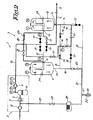
図1は、主として圧縮機2と本発明の乾燥機3とから成る圧縮装置1を示す。 FIG. 1 shows a compression device 1 mainly comprising a compressor 2 and a dryer 3 according to the invention.
圧縮機2は、主として低圧力段4と高圧力段5とから成り、これらは圧力管6によって直列に連結され、この圧力管には、中間冷却器7と水分離器8とが取りつけてある。 The compressor 2 mainly comprises a low pressure stage 4 and a high pressure stage 5, which are connected in series by a pressure pipe 6, to which an intercooler 7 and a water separator 8 are attached. .
乾燥機3は、シリカゲルその他の乾燥剤を収容している、入口10と出口11とを有する第一の独立圧力容器9、やはり乾燥剤としてのシリカゲルを収容している、入口13と出口14とを有する第二の独立圧力容器12、冷却器15、および止め栓17と弁18とを有する管16から成る。管16は、圧縮機2を圧力容器9と12とに連結し、圧縮気体を乾燥し、圧力容器内の乾燥剤を再生し、ユーザーネットワーク19に接続することを可能にする。
The dryer 3 contains a silica gel or other desiccant, a first independent pressure vessel 9 having an
追加管20、21のそれぞれと止め栓22とが備えられ、これらによって、圧縮機2の高温圧縮気体の少なくとも一部を、圧力容器9と12の一つを経て、二つの圧力段4と5との間の圧力管6に導くことが可能になる。
Each of the
管20は、二つの圧力容器9と12の出口11と14との間で、閉鎖することのできるブリッジを形成しており、また圧力逃がし弁23を有する。
The
管21は、圧力容器9と12の入口10と13のそれぞれを、圧力管6に、より詳しくは中間冷却器7の入口の圧力管6の部分に接続し、またフィルター24と弁25とを有する。
The
管21は、栓26によって大気に接続することができ、栓26は、弁27を有し、また随意に吸音器28を備えることができ、再生圧力容器9内の圧力を二つの圧力段4、5の間の圧力管6内の圧力に戻すようになっている。
The
圧縮装置1と乾燥機3との動作は簡単であり、図1〜3によって説明される。これらの図において、止め栓17と22は、閉鎖位置にあるとき、黒塗りで示され、開放位置にあるとき、白で示される。また、圧縮気体の経路は太線で示される。
The operation of the compressor 1 and the dryer 3 is simple and will be explained with reference to FIGS. In these figures,
図1に示す第一の段階においては、圧縮機2の非冷却圧縮気体流の全体が、より詳しくは高圧力段5からの気体流が、圧力容器9を逆向きに通過させられ、この容器内で、圧縮気体流は、それに含まれる熱によって、乾燥剤または除湿剤たとえばシリカゲルを再生する。 In the first stage shown in FIG. 1, the entire uncooled compressed gas stream of the compressor 2 and more specifically the gas stream from the high pressure stage 5 is passed through the pressure vessel 9 in the opposite direction. Within, the compressed gas stream regenerates a desiccant or a dehumidifying agent such as silica gel by the heat contained therein.
次に、圧縮気体流は冷却器にいたり、該冷却器においてさらに冷却され、それから、圧縮気体は、圧力容器12を通過させられ、乾燥される。
The compressed gas stream then enters a cooler and is further cooled in the cooler, and then the compressed gas is passed through the
このとき、圧力容器12の出口14は、図示しない1つ以上の圧縮空気ユーザーが接続しているユーザーネットワーク19に連結されている。
At this time, the
第二の段階においては、図2に示す、本発明による、再生圧力容器9内の乾燥剤の再生サイクルの終了時に、送出圧縮気体の全体が順次に冷却器15とさらに乾燥すべき圧力容器12とを通過させられ、そのあと、冷却気体の一部がユーザーネットワーク19に供給される。残りの部分は、管20を経て、圧力容器9内を逆向きに通過させられ、圧力容器9内の乾燥剤が冷却される。該部分は、さらに、管21とフィルター24を経て、中間冷却器7を有する圧力管6に導かれる。
In the second stage, as shown in FIG. 2, at the end of the regeneration cycle of the desiccant in the regeneration pressure vessel 9 according to the present invention, the entire delivered compressed gas is sequentially transferred to the
冷却のために弁25が開放される前に、冷却の必要のある、最終圧力にある圧力容器9が、弁27と吸音器28により開放されて、中間冷却器7の圧力と同じ圧力とされ、中間冷却器7に対する圧力衝撃の発生が防がれるようになっている。
Before the valve 25 is opened for cooling, the pressure vessel 9 at the final pressure that needs to be cooled is opened by the
乾燥剤を冷却するために再生圧力容器9を通過する送出気体の一部は、圧力逃がし弁23によって放出され、そのため、さらなる冷却が起こりうる。
A portion of the delivery gas that passes through the regeneration pressure vessel 9 to cool the desiccant is released by the
送出気体のこの部分は、中間冷却器7の入口に放出され、そのあと、高圧力段5によってふたたび圧縮される。そのため、圧縮気体が失われることがなく、中間冷却器の圧力たとえば3 barまで気体を圧縮するのに必要なエネルギーが回収される。 This part of the delivery gas is discharged to the inlet of the intercooler 7 and is then compressed again by the high pressure stage 5. Therefore, the compressed gas is not lost, and the energy required to compress the gas up to the pressure of the intercooler, for example 3 bar, is recovered.
圧力逃がし弁23は、好ましくは、圧縮機2の出口の公称最終圧力たとえば8 barから中間冷却器の圧力たとえば3 barへの気体の膨張が、圧力逃がし弁23において起こるように、選択または設定される。
The
乾燥剤が冷却される前に、再生圧力容器9を通過する送出気体の一部は、好ましくは、圧縮機2によって圧縮される送出気体の全体の一部分であり、好ましくはこの一部分は、圧縮機全送出量の6%の程度である。 Before the desiccant is cooled, the part of the delivery gas that passes through the regeneration pressure vessel 9 is preferably part of the whole delivery gas that is compressed by the compressor 2, preferably this part is the compressor It is about 6% of the total delivery amount.
図3に示すように、第三および最終段階においては、再生圧力容器9が乾燥圧力容器となり、乾燥圧力容器が再生圧力容器となるように、圧力容器が切換えられる直前に、湿った圧縮気体が、短時間、冷却器15を経て、二つの圧力容器9と12に送られる。これにより、再生圧力容器9は、さらにある程度冷却され、また、ほぼ飽和した圧力容器12の飽和がある程度小さくなる。
As shown in FIG. 3, in the third and final stages, immediately before the pressure vessel is switched so that the regeneration pressure vessel 9 becomes a dry pressure vessel and the dry pressure vessel becomes a regeneration pressure vessel, the wet compressed gas is After a short time, it passes through the
第二および第三段階の結果として、圧力容器9と12の前記切換えの時点での、露点および温度の上昇は最小限に抑えられる。
As a result of the second and third stages, the increase in dew point and temperature at the time of the switching of the
必要であれば、乾燥機3は、圧力容器9と12内に取りつけられ、乾燥プロセスを促進し最適化するために作動させることのできる加熱要素29によって、補完することができる。
If necessary, the dryer 3 can be supplemented by a
明らかに、乾燥プロセスの前記第二段階において、再生またはほぼ再生された乾燥剤の冷却に使用される圧縮気体の一部は、必ずしも乾燥圧力容器12の出口14から放出する必要はないが、そうするのが好ましい。
Obviously, in the second stage of the drying process, the portion of the compressed gas used to cool the regenerated or nearly regenerated desiccant need not necessarily be released from the
やはり明らかに、圧縮機2は、二つ以上の圧力段4、5から成ることができ、また中間冷却器7は必須ではない。この場合、再生乾燥剤の冷却のために使用される気体は、必要に応じて二つの連続圧力段の間に導くことができる。 Obviously, the compressor 2 can consist of two or more pressure stages 4, 5 and the intercooler 7 is not essential. In this case, the gas used for the cooling of the regenerated desiccant can be led between two successive pressure stages as required.
やはり明らかに、乾燥剤としては、シリカゲルではなく他の乾燥剤も適当である。 Obviously, as the desiccant, other desiccants than silica gel are also suitable.
装置1と圧縮機2には、圧力測定器PI、温度測定器TT、露点測定器TS、および送出量測定器PTを、出口における乾燥空気の必要品質に応じて装置1のサイクルとエネルギー消費とを制御する制御器(図示せず)とともに、備えることができる。この場合、止め栓17と22とが制御される止め栓であり、これらが前記制御器によって制御できる。
The device 1 and the compressor 2 include a pressure measuring device PI, a temperature measuring device TT, a dew point measuring device TS, and a delivery amount measuring device PT according to the required quality of the dry air at the outlet and the cycle and energy consumption of the device 1. And a controller (not shown) for controlling. In this case, the
また、圧力逃がし弁23は、必要であれば、前記制御器によって設定して、制御し、乾燥プロセスの前記第二および第三段階が最適に進行するようにすることができる。
Also, if necessary, the
本発明は、また、他のタイプの乾燥剤乾燥機にも適用できる。たとえば、圧力容器が同一の乾燥機のいわゆる分離区画室として作られ、共通の乾燥剤がこれらの区画室において使用され、これらの区画室が回転するようになっており、前記乾燥剤の部分が二つの区画室のそれぞれに存在するようになっており、一つの区画室内の乾燥剤部分が圧縮気体の乾燥に使用され、他の区画室内の乾燥剤部分が再生されるようになっている回転乾燥剤乾燥機に使用することができる。 The present invention is also applicable to other types of desiccant dryers. For example, the pressure vessel is made as a so-called separation compartment of the same dryer, a common desiccant is used in these compartments, these compartments rotate, and the desiccant part is A rotation that is present in each of the two compartments so that the desiccant part in one compartment is used for drying the compressed gas and the desiccant part in the other compartment is regenerated. Can be used in desiccant dryers.
本発明は、無潤滑式(oil-free)および油噴射式(oil-injected)圧縮機を含む、異なるタイプの圧縮機の組合せにも適用することができる。 The present invention can also be applied to combinations of different types of compressors, including oil-free and oil-injected compressors.
明らかに、本発明は上で説明した方法とそれに使用される装置のみに限定されるものではなく、本発明の範囲を逸脱することなく、すべての種類の形状と組合せで具体化することができる。 Obviously, the present invention is not limited to the method described above and the apparatus used therein, but can be embodied in all kinds of shapes and combinations without departing from the scope of the present invention. .
1 圧縮装置
2 圧縮機
3 乾燥機
4 低圧力段
5 高圧力段
6 圧力管
7 中間冷却器
8 水分離器
9 第一の独立圧力容器
10 入口
11 出口
12 第二の独立圧力容器
13 入口
14 出口
15 冷却器
16 管
17 止め栓
18 弁
19 ユーザーネットワーク
20 追加管
21 追加管
22 止め栓
23 圧力逃がし弁
24 フィルター
25 弁
26 栓
27 弁
28 吸音器
29 加熱要素
PI 圧力測定器
PT 送出量測定器
TS 露点測定器
TT 温度測定器
1 Compression device
2 Compressor
3 Dryer
4 Low pressure stage
5 High pressure stage
6 Pressure pipe
7 Intermediate cooler
8 Water separator
9 First independent pressure vessel
10 entrance
11 Exit
12 Second independent pressure vessel
13 entrance
14 Exit
15 Cooler
16 tubes
17 Stopcock
18 valves
19 User network
20 Additional pipe
21 Additional pipe
22 Stopcock
23 Pressure relief valve
24 filters
25 valves
26 stopper
27 valves
28 Sound absorber
29 Heating elements
PI pressure measuring instrument
PT delivery meter
TS dew point measuring instrument
TT temperature measuring instrument
Claims (12)
乾燥機(3)が、除湿剤または乾燥剤を装填した少なくとも二つの圧力容器(9、12)とともに使用され、該圧力容器(9、12)が交互に作動し、一つの圧力容器(12)が作動して圧縮気体を乾燥しているとき、もう一つの圧力容器(9)が再生されるようになっており、ここで、圧縮気体を乾燥するために、この気体をまず冷却器(15)内で冷却し、次に乾燥圧力容器(12)を通過させ、またここで、もう一つの圧力容器(9)を再生するために、この圧縮気体の少なくとも一部を再生圧力容器(9)を通過させるような方法において、
少なくとも再生圧力容器(9)の再生サイクルの終了時に、圧縮気体の前記一部を、該一部が前記再生圧力容器を通過したあと、二つの圧力段(4、5)の間の圧力管(6)に導く、
ことを特徴とする方法。A method for drying compressed gas in a compressor (1) comprising a compressor (2) having at least two pressure stages (4, 5) connected in series,
A dryer (3) is used with at least two pressure vessels (9, 12) loaded with a dehumidifying agent or desiccant, the pressure vessels (9, 12) operating alternately, and one pressure vessel (12) Is activated to dry the compressed gas, another pressure vessel (9) is regenerated where the gas is first cooled in the cooler (15 to dry the compressed gas. ) And then passed through a drying pressure vessel (12) where, at least part of this compressed gas is regenerated to regenerate another pressure vessel (9). In such a way as to pass
At least at the end of the regeneration cycle of the regeneration pressure vessel (9), the part of the compressed gas is passed through the pressure tube between the two pressure stages (4, 5) after the part has passed through the regeneration pressure vessel ( 6),
A method characterized by that.
主として、
除湿剤または乾燥剤を装填した少なくとも二つの圧力容器(9、12)であって、これらの圧力容器(9、12)が交互に作動し、一つの圧力容器(12)が作動して圧縮気体を乾燥しているとき、もう一つの圧力容器(9)が再生されるようになっている圧力容器(9、12)と、
圧縮気体を冷却するための冷却器(15)と、
圧縮機(2)を前記圧力容器(9、12)に連結する、止め栓(17)を有する管(16)と、
から成り、
追加管(20、21)および止め栓(22)が備えられて、これにより、圧縮機(2)からの圧縮気体の少なくとも一部を、冷却器(15)および圧力容器(12)を通過したあと、再生圧力容器(9)を経て、二つの圧力段(4、5)の間の圧力管(6)に導くことが可能になる、
ことを特徴とする装置。An apparatus for drying compressed gas from a compressor (2) having at least two pressure stages (4, 5) connected in series;
mainly,
At least two pressure vessels (9, 12) loaded with a dehumidifying agent or desiccant, these pressure vessels (9, 12) are operated alternately, and one pressure vessel (12) is operated to generate compressed gas. A pressure vessel (9, 12) adapted to regenerate another pressure vessel (9) when drying
A cooler (15) for cooling the compressed gas;
A pipe (16) having a stopcock (17) for connecting the compressor (2) to the pressure vessel (9, 12);
Consisting of
Additional tubes (20, 21) and stopcocks (22) were provided so that at least a portion of the compressed gas from the compressor (2) passed through the cooler (15) and the pressure vessel (12). After that, it becomes possible to lead to the pressure pipe (6) between the two pressure stages (4, 5) via the regeneration pressure vessel (9),
A device characterized by that.
Applications Claiming Priority (2)
| Application Number | Priority Date | Filing Date | Title |
|---|---|---|---|
| BE2004/0553A BE1016309A3 (en) | 2004-11-10 | 2004-11-10 | METHOD FOR DRYING COMPRESSED GAS AND APPARATUS APPLIED THEREOF |
| PCT/BE2005/000149 WO2006050582A1 (en) | 2004-11-10 | 2005-10-20 | Method for drying compressed gas and device used thereby |
Publications (2)
| Publication Number | Publication Date |
|---|---|
| JP2008519929A JP2008519929A (en) | 2008-06-12 |
| JP4667467B2 true JP4667467B2 (en) | 2011-04-13 |
Family
ID=34974340
Family Applications (1)
| Application Number | Title | Priority Date | Filing Date |
|---|---|---|---|
| JP2007540460A Active JP4667467B2 (en) | 2004-11-10 | 2005-10-20 | Method for drying compressed gas and apparatus used therefor |
Country Status (14)
| Country | Link |
|---|---|
| US (1) | US7691183B2 (en) |
| EP (1) | EP1809406B2 (en) |
| JP (1) | JP4667467B2 (en) |
| KR (1) | KR100891908B1 (en) |
| CN (1) | CN101056691B (en) |
| AT (1) | ATE399588T1 (en) |
| BE (1) | BE1016309A3 (en) |
| BR (1) | BRPI0517698B1 (en) |
| DE (1) | DE602005007927D1 (en) |
| DK (1) | DK1809406T4 (en) |
| ES (1) | ES2309808T5 (en) |
| PL (1) | PL1809406T5 (en) |
| PT (1) | PT1809406E (en) |
| WO (1) | WO2006050582A1 (en) |
Families Citing this family (20)
| Publication number | Priority date | Publication date | Assignee | Title |
|---|---|---|---|---|
| BE1017776A3 (en) * | 2007-10-04 | 2009-06-02 | Atlas Copco Airpower Nv | METHOD FOR DRYING COMPRESSED GAS |
| FR2924357A1 (en) * | 2007-11-30 | 2009-06-05 | Air Liquide | METHOD AND APPARATUS FOR DRYING CARBON DIOXIDE RICH GAS RATE |
| DE102009002047B4 (en) * | 2009-03-31 | 2012-07-26 | Kaeser Kompressoren Gmbh | Method for controlling the cooling phase of a container to be cooled, a heat-regenerating adsorption system and apparatus of a heat-regenerating adsorption system for carrying out such a method |
| ES2354337B1 (en) * | 2009-05-07 | 2011-10-07 | Abengoa Solar New Technologies S.A. | PHOTOVOLTAIC MODULES DEHUMIDIFIER. |
| IT1395955B1 (en) * | 2009-06-19 | 2012-11-02 | Parker Hannifin Srl | "PROCEDURE AND APPARATUS FOR GAS COMPRESSED DRYING" |
| BE1018854A3 (en) | 2009-08-11 | 2011-10-04 | Atlas Copco Airpower Nv | DRYER FOR COMPRESSED GAS AND METHOD THEREFORE APPLIED. |
| US8425673B2 (en) * | 2010-07-16 | 2013-04-23 | Solution Dynamics | Regenerative dryers with a bypass |
| KR101083713B1 (en) * | 2011-01-14 | 2011-11-15 | (주)세한플랜트 | Non heating type compressed air drying system |
| CN102228773B (en) * | 2011-06-02 | 2013-12-18 | 杭州溢达机电制造有限公司 | Afterheat regeneration absorbing type desiccator |
| DE102013109476A1 (en) * | 2013-08-30 | 2015-03-05 | Knorr-Bremse Systeme für Schienenfahrzeuge GmbH | Method and device for the regeneration of a two-chamber air dryer |
| DE102015209210A1 (en) * | 2015-05-20 | 2016-11-24 | Mahle International Gmbh | Intercooler |
| WO2016205902A2 (en) | 2015-06-23 | 2016-12-29 | Katholieke Universiteit Leuven Ku Leuven Research & Development | Compositions and methods for treating biofilms |
| EP3108953B1 (en) * | 2015-06-25 | 2022-06-15 | Ateliers François | Method for compressing and drying a gas |
| BE1023302B1 (en) | 2015-07-23 | 2017-01-26 | Atlas Copco Airpower Naamloze Vennootschap | Process for the manufacture of an adsorbent for treating compressed gas, adsorbent obtained with such a process and adsorption device provided with such adsorbent |
| DK3344367T3 (en) | 2015-08-31 | 2020-12-07 | Atlas Copco Airpower Nv | Adsorption device for compressed gas |
| BE1027361B1 (en) * | 2019-06-12 | 2021-01-20 | Atlas Copco Airpower Nv | Compressor plant and method for supplying compressed gas |
| CN110185599A (en) * | 2019-06-19 | 2019-08-30 | 沈阳理工大学 | New hydrogen circulating hydrogen compressor |
| BE1027873B1 (en) * | 2019-12-17 | 2021-07-15 | Atlas Copco Airpower Nv | Method of drying compressed gas |
| BE1027958B1 (en) * | 2020-01-02 | 2021-08-05 | Atlas Copco Airpower Nv | Drying device and method for drying compressed gas |
| BE1028688B1 (en) * | 2020-10-09 | 2022-05-09 | Atlas Copco Airpower Nv | Device and method for drying compressed gas and compressor installation provided with such device |
Citations (9)
| Publication number | Priority date | Publication date | Assignee | Title |
|---|---|---|---|---|
| JPS56159687U (en) * | 1980-04-28 | 1981-11-28 | ||
| JPS6282382U (en) * | 1985-11-13 | 1987-05-26 | ||
| JPS6295721U (en) * | 1985-12-05 | 1987-06-18 | ||
| JPH0623228A (en) * | 1992-04-15 | 1994-02-01 | Atlas Copco Airpower Nv | Gas drier |
| JPH10323532A (en) * | 1997-05-27 | 1998-12-08 | Nabco Ltd | Two-cylinder dehumidifier |
| JP2000176235A (en) * | 1998-12-14 | 2000-06-27 | Atlas Copco Airpower Nv | Method for drying gas and device therefor |
| US6171377B1 (en) * | 1999-07-14 | 2001-01-09 | Henderson Engineering Co., Inc. | Regenerative compressed air/gas dryer |
| US6221130B1 (en) * | 1999-08-09 | 2001-04-24 | Cooper Turbocompressor, Inc. | Method of compressing and drying a gas and apparatus for use therein |
| US20030233941A1 (en) * | 2002-06-25 | 2003-12-25 | Cooper Turbocompressor, Inc. | Energy efficient desiccant dryer regeneration system |
Family Cites Families (18)
| Publication number | Priority date | Publication date | Assignee | Title |
|---|---|---|---|---|
| US1934075A (en) * | 1928-11-12 | 1933-11-07 | Standard Oil Dev Co | Process for the treatment of gases |
| US1948779A (en) * | 1931-06-30 | 1934-02-27 | Chester F Hockley | Adsorption system |
| US1959389A (en) * | 1931-07-02 | 1934-05-22 | Chester F Hockley | Adsorption system |
| US2747681A (en) * | 1951-09-05 | 1956-05-29 | British Oxygen Co Ltd | Regeneration of adsorbent units |
| US3205638A (en) * | 1963-06-12 | 1965-09-14 | Phillips Petroleum Co | Method and apparatus for dehydration of gases |
| US3446479A (en) * | 1965-12-01 | 1969-05-27 | Borsig Ag | Valve with ball-shaped stop cock |
| US3568406A (en) * | 1968-10-28 | 1971-03-09 | Ingersoll Rand Co | Desiccant air dryer |
| JPS5250979A (en) * | 1975-10-22 | 1977-04-23 | Kuri Kagaku Sochi Kk | Method of condensing or liquefying a specific component |
| US4283212A (en) * | 1978-04-07 | 1981-08-11 | Boc Limited | Treatment of gas streams |
| US4761968A (en) * | 1987-10-13 | 1988-08-09 | Pioneer Air Systems, Inc. | High efficiency air drying system |
| DE3878900D1 (en) † | 1988-03-25 | 1993-04-08 | Otto Oeko Tech | DEVICE FOR THE RECOVERY OF HYDROCARBONS FROM HIGHLY CONCENTRATED GAS FLOWS. |
| US4898599A (en) * | 1989-05-12 | 1990-02-06 | Pneumatic Products Corporation | Desiccant gas drying system |
| US5234479A (en) † | 1992-07-02 | 1993-08-10 | Henderson Terry D | Compressed natural gas dryer system and method of operation |
| GB9412310D0 (en) * | 1994-06-20 | 1994-08-10 | Boc Group Plc | Recovery of substances from exhaust streams |
| US5669962A (en) † | 1996-03-15 | 1997-09-23 | Uop | Rapid thermal swing dryer for compressed gases |
| US6375722B1 (en) * | 2000-08-22 | 2002-04-23 | Henderson Engineering Co., Inc. | Heat of compression dryer |
| BE1013828A3 (en) * | 2000-11-08 | 2002-09-03 | Atlas Copco Airpower Nv | Method for controlling a compressor plant with a dryer and thus used compressor installation. |
| CN2495363Y (en) * | 2001-02-26 | 2002-06-19 | 杭州汉业气源净化设备有限公司 | Apparatus for purifying and drying pressed air |
-
2004
- 2004-11-10 BE BE2004/0553A patent/BE1016309A3/en not_active IP Right Cessation
-
2005
- 2005-10-20 PL PL05801577T patent/PL1809406T5/en unknown
- 2005-10-20 DE DE602005007927T patent/DE602005007927D1/en active Active
- 2005-10-20 CN CN2005800384208A patent/CN101056691B/en active Active
- 2005-10-20 AT AT05801577T patent/ATE399588T1/en active
- 2005-10-20 PT PT05801577T patent/PT1809406E/en unknown
- 2005-10-20 ES ES05801577T patent/ES2309808T5/en active Active
- 2005-10-20 DK DK05801577.7T patent/DK1809406T4/en active
- 2005-10-20 US US11/667,351 patent/US7691183B2/en active Active
- 2005-10-20 JP JP2007540460A patent/JP4667467B2/en active Active
- 2005-10-20 WO PCT/BE2005/000149 patent/WO2006050582A1/en active IP Right Grant
- 2005-10-20 BR BRPI0517698A patent/BRPI0517698B1/en active IP Right Grant
- 2005-10-20 EP EP05801577A patent/EP1809406B2/en active Active
- 2005-10-20 KR KR1020077010874A patent/KR100891908B1/en active IP Right Grant
Patent Citations (9)
| Publication number | Priority date | Publication date | Assignee | Title |
|---|---|---|---|---|
| JPS56159687U (en) * | 1980-04-28 | 1981-11-28 | ||
| JPS6282382U (en) * | 1985-11-13 | 1987-05-26 | ||
| JPS6295721U (en) * | 1985-12-05 | 1987-06-18 | ||
| JPH0623228A (en) * | 1992-04-15 | 1994-02-01 | Atlas Copco Airpower Nv | Gas drier |
| JPH10323532A (en) * | 1997-05-27 | 1998-12-08 | Nabco Ltd | Two-cylinder dehumidifier |
| JP2000176235A (en) * | 1998-12-14 | 2000-06-27 | Atlas Copco Airpower Nv | Method for drying gas and device therefor |
| US6171377B1 (en) * | 1999-07-14 | 2001-01-09 | Henderson Engineering Co., Inc. | Regenerative compressed air/gas dryer |
| US6221130B1 (en) * | 1999-08-09 | 2001-04-24 | Cooper Turbocompressor, Inc. | Method of compressing and drying a gas and apparatus for use therein |
| US20030233941A1 (en) * | 2002-06-25 | 2003-12-25 | Cooper Turbocompressor, Inc. | Energy efficient desiccant dryer regeneration system |
Also Published As
| Publication number | Publication date |
|---|---|
| KR100891908B1 (en) | 2009-04-06 |
| BRPI0517698B1 (en) | 2016-07-12 |
| EP1809406A1 (en) | 2007-07-25 |
| BRPI0517698A (en) | 2008-10-14 |
| PL1809406T5 (en) | 2013-03-29 |
| CN101056691A (en) | 2007-10-17 |
| WO2006050582A1 (en) | 2006-05-18 |
| DK1809406T4 (en) | 2012-11-12 |
| ES2309808T5 (en) | 2013-02-01 |
| PL1809406T3 (en) | 2009-05-29 |
| KR20070087559A (en) | 2007-08-28 |
| DE602005007927D1 (en) | 2008-08-14 |
| ATE399588T1 (en) | 2008-07-15 |
| DK1809406T3 (en) | 2008-10-13 |
| BE1016309A3 (en) | 2006-07-04 |
| US7691183B2 (en) | 2010-04-06 |
| CN101056691B (en) | 2010-10-06 |
| EP1809406B1 (en) | 2008-07-02 |
| ES2309808T3 (en) | 2008-12-16 |
| EP1809406B2 (en) | 2012-09-19 |
| PT1809406E (en) | 2008-09-19 |
| JP2008519929A (en) | 2008-06-12 |
| US20070295205A1 (en) | 2007-12-27 |
Similar Documents
| Publication | Publication Date | Title |
|---|---|---|
| JP4667467B2 (en) | Method for drying compressed gas and apparatus used therefor | |
| JP5031816B2 (en) | Apparatus for drying compressed gas and method of using the same | |
| JP4800308B2 (en) | Improved compression device | |
| BE1010132A3 (en) | Method and device for drying by a compressor compressed gas. | |
| JP2008508466A5 (en) | ||
| KR101012782B1 (en) | Device for drying compressed gas | |
| CN216136959U (en) | Device for adsorbing gas from gas mixture to be treated | |
| US20220213881A1 (en) | Compressor system and method for supplying compressed gas | |
| EP3108953B1 (en) | Method for compressing and drying a gas | |
| JP2008030001A (en) | Dehumidification method of wet gas and dehumidification system therefor | |
| RU2701016C2 (en) | Method of producing oxygen by vpsa | |
| JP2012135701A (en) | Oilless dry compressed air producing system | |
| US20140246622A1 (en) | Heat reactivated adsorbent gas fractionator and process | |
| JPS6087830A (en) | Regenerating process of drying agent for dehumidifyer of compressed gas | |
| AU2020290081A1 (en) | Drying device and method for drying a compressed gas | |
| JPS6349224A (en) | Reversible heating and regeneration type dehumidifier by pressurized gas | |
| JP2004209368A (en) | Gas separation apparatus | |
| JP2002028432A (en) | Pretreating device for air separating device | |
| JP2002136832A (en) | Method for regenerating dehumidifier for low dew point compressed air and dehumidifying system for low dew point compressed air | |
| JPH07204445A (en) | Dehumidifying method |
Legal Events
| Date | Code | Title | Description |
|---|---|---|---|
| A621 | Written request for application examination |
Free format text: JAPANESE INTERMEDIATE CODE: A621 Effective date: 20080516 |
|
| TRDD | Decision of grant or rejection written | ||
| A01 | Written decision to grant a patent or to grant a registration (utility model) |
Free format text: JAPANESE INTERMEDIATE CODE: A01 Effective date: 20101221 |
|
| A01 | Written decision to grant a patent or to grant a registration (utility model) |
Free format text: JAPANESE INTERMEDIATE CODE: A01 |
|
| A61 | First payment of annual fees (during grant procedure) |
Free format text: JAPANESE INTERMEDIATE CODE: A61 Effective date: 20110111 |
|
| FPAY | Renewal fee payment (event date is renewal date of database) |
Free format text: PAYMENT UNTIL: 20140121 Year of fee payment: 3 |
|
| R150 | Certificate of patent or registration of utility model |
Ref document number: 4667467 Country of ref document: JP Free format text: JAPANESE INTERMEDIATE CODE: R150 |
|
| R250 | Receipt of annual fees |
Free format text: JAPANESE INTERMEDIATE CODE: R250 |
|
| R250 | Receipt of annual fees |
Free format text: JAPANESE INTERMEDIATE CODE: R250 |
|
| R250 | Receipt of annual fees |
Free format text: JAPANESE INTERMEDIATE CODE: R250 |
|
| R250 | Receipt of annual fees |
Free format text: JAPANESE INTERMEDIATE CODE: R250 |
|
| R250 | Receipt of annual fees |
Free format text: JAPANESE INTERMEDIATE CODE: R250 |
|
| R250 | Receipt of annual fees |
Free format text: JAPANESE INTERMEDIATE CODE: R250 |
|
| R250 | Receipt of annual fees |
Free format text: JAPANESE INTERMEDIATE CODE: R250 |
|
| R250 | Receipt of annual fees |
Free format text: JAPANESE INTERMEDIATE CODE: R250 |
|
| R250 | Receipt of annual fees |
Free format text: JAPANESE INTERMEDIATE CODE: R250 |
|
| R250 | Receipt of annual fees |
Free format text: JAPANESE INTERMEDIATE CODE: R250 |
|
| R250 | Receipt of annual fees |
Free format text: JAPANESE INTERMEDIATE CODE: R250 |