JP4666434B2 - Pressure reducing valve - Google Patents
Pressure reducing valve Download PDFInfo
- Publication number
- JP4666434B2 JP4666434B2 JP2001036798A JP2001036798A JP4666434B2 JP 4666434 B2 JP4666434 B2 JP 4666434B2 JP 2001036798 A JP2001036798 A JP 2001036798A JP 2001036798 A JP2001036798 A JP 2001036798A JP 4666434 B2 JP4666434 B2 JP 4666434B2
- Authority
- JP
- Japan
- Prior art keywords
- pressure reducing
- valve body
- reducing valve
- port
- valve stem
- Prior art date
- Legal status (The legal status is an assumption and is not a legal conclusion. Google has not performed a legal analysis and makes no representation as to the accuracy of the status listed.)
- Expired - Lifetime
Links
Images


Landscapes
- Sealing Devices (AREA)
- Control Of Fluid Pressure (AREA)
Description
【0001】
【発明の属する技術分野】
本発明は、減圧弁に関する。
【0002】
【従来の技術】
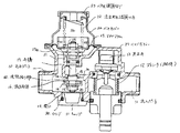
従来の減圧弁について図6、図7を参照して説明する。図6は従来の減圧弁の構造を示す断面図であり、図7はその部分拡大図である。
【0003】
水は流入ポート11からストレーナ12を通り、逆止弁13を押し上げ、隔壁14に設けられた減圧ポート15に達する。減圧ポート15の2次側には減圧弁体16が配置されている。この減圧弁体16は、弁棒17の一端に弁体カバー18、ワッシャー19及びナット20によって保持されている。弁棒17の途中部分は、筒状の減圧弁保持部21により摺動自在に保持されている。弁棒17の他端には流出水圧調節バネ22が取付けられており、流出水圧調節バネ22はバネ圧調節ネジ23に反力を得て弁棒17を押圧している。
【0004】
流出水圧調節バネ22は、バネカバー24とダイヤフラム25とで囲まれたバネ設置室26内に配置されている。ダイヤフラム25の外周部はバネカバー24とバルブボディー27との間に狭持されている。ダイヤフラム25の中央開口部の縁部は、弁棒17のフランジ17aとナット28との間に狭持されている。バルブボディー27には、減圧弁体16をバルブボディー27内に挿入するための開口29が設けられている。この開口29はOリング30を保持したキャップ31により閉鎖されている。
【0005】
給水圧が設定圧よりも高い時に2次側を止水した場合、ダイヤフラム25が水圧によって上方に押圧移動され、減圧弁体16が減圧ポート15のシール部15aに密着し2次側の圧力が設定圧に保持される。この設定圧は、バネ圧調節ネジ23を回すことにより調節される。
【0006】
給水圧が設定圧よりも高い時に2次側を止水した後、2次側を通水した場合、ダイヤフラム25を押上げる圧力が下がり減圧弁体16が減圧ポート15のシール部15aより離れ、2次側の必要流量に応じた弁開口ストローク、すなわち通水断面積を確保した状態で安定する。この安定状態においては、図7に拡大して示すように、減圧ポート15のシール部15aと減圧弁体16との隙間(流路絞り部60)は、弁棒17と減圧ポート15との隙間より小さくなっている。
【0007】
【発明が解決しようとする課題】
しかしながら、上記した従来の構成では、安定状態において減圧ポート15のシール部15aと減圧弁体16との隙間が小さいため、ストレーナ12を通過したやや大き目の異物が、弁棒17と減圧ポート15との隙間を通過した後、減圧ポート15のシール部15aと減圧弁体16との隙間に噛み込んでしまうことがあるという問題があった。
【0008】
この場合、2次側を止水した時に減圧弁体16が減圧ポート15のシール部15aに完全に密着することができなくなり、2次側を設定圧に保つことができない。噛み込んだ異物は、2次側の通水−止水操作により流出ポート32側に流出することもあるが、噛み込んだ際に減圧弁体16に傷が付き、減圧弁体16から2次側に圧力が漏れ設定圧で保持できなくなる場合もある。減圧弁は、分解するとバネの再設定を行わなければならないなど現場での修理は難しいため、減圧弁自体の交換が必要となる。このため、メンテナンス性が悪く修理費用が高い。
【0009】
本発明は、上記課題を解決するためになされたもので、本発明の目的は、異物の噛み込みを防いで故障の発生を防止できる減圧弁を提供することにある。
【0010】
【課題を解決するための手段・作用及び効果】
上記目的を達成するために請求項1では、弁棒17と、弁棒17の一端に取付けられ弁棒17を常時開方向に付勢する流出水圧調節バネ22と、弁棒17の一端に取付けられ弁棒17を給水圧により閉方向に付勢するダイヤフラム25と、弁棒17の他端に取付けられた減圧弁体16と、1次側と2次側を隔てる隔壁14に設けた減圧ポート15と、減圧ポート15のシール部15aと減圧弁体16との隙間である流路絞り部60とを備えた減圧弁において、減圧ポート15にテーパ状の段部を設けるとともに、該段部と略同テーパの段部を弁棒17にも設け、弁棒17の径は、段部から減圧弁体16の区間の径が段部よりダイヤフラム25側の径よりも太径となるように形成されており、減圧弁体16が減圧ポート15のシール部15aに密着している状態では、弁棒17の段部より減圧弁体16側の太径の部分が減圧ポート15を貫通しており、減圧弁体16が減圧ポート15のシール部15aから離れてから所定の間は、弁棒17の段部より減圧弁体16側の太径の部分が減圧ポート15を貫通した状態を継続し、その後、更に減圧弁体16が減圧ポート15のシール部15aから離れて停止した安定状態においては、弁棒17の段部よりダイヤフラム25側の部分が減圧ポート15を貫通し、減圧ポート15に設けられたテーパ状の段部と弁棒17の段部とが対向し、それにより、安定状態において、減圧ポート15に設けられたテーパ状の段部と弁棒17の段部とが対向した隙間より、流路絞り部60を形成している減圧ポート15のシール部15aと減圧弁体16との隙間の方が大きくなることを特徴とする。
よって、弁棒17と減圧ポート15との隙間で決まるこの部分の通水断面積は、減圧弁体16が減圧ポート15のシール部15aから離れてから所定の間は、弁棒17の段部より減圧弁体16側の太径と減圧ポート15との隙間となり、その後、更に減圧弁体16が減圧ポート15のシール部15aから離れて停止した安定状態においては、それぞれに設けられたテーパ状の段部のためその相対位置により変化するが、通水断面積としては狭くすることができるので、弁棒17と減圧ポート15との間で給水圧を減圧するようにし、ダイヤフラム25を押上げる圧力を軽減させることができる。これにより、減圧ポート15のシール部15aと減圧弁体16との隙間(流路絞り部60)が大きくなるため、異物が流路絞り部60に噛み込むことがなく、減圧ポート15のシール部15aと減圧弁体16とを密着させることができる。
【0011】
また、本発明においては、弁棒17に設けた前記段部およびその段部よりも減圧弁体16側の太径の部分を、ゴム50により被覆したことを特徴とする。
よって、減圧ポート15と弁棒17のテーパ状の段部に異物が噛み込んだとしても、ゴム50が弾性変形して異物を吸収するため、弁棒17の摺動を妨げない。
【0012】
【発明の実施の形態】
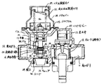
以下、本発明の実施例を添付図面に基づいて説明する。図1は本発明の第一実施例である減圧弁の構造を示す断面図であり、図2、図3はその部分拡大図である。
【0013】
水は流入ポート11からストレーナ12を通り、逆止弁13を押し上げ、隔壁14に設けられた減圧ポート15に達する。減圧ポート15の2次側には減圧弁体16が配置されている。この減圧弁体16は、弁棒17の一端に弁体カバー18、ワッシャー19及びナット20によって保持されている。弁棒17の途中部分は、筒状の減圧弁保持部21により摺動自在に保持されている。弁棒17の他端には流出水圧調整バネ22が取付けられており、流出水圧調整バネ22はバネ圧調整ネジ23に反力を得て弁棒17を押圧している。
【0014】
流出水圧調整バネ22は、バネカバー24とダイヤフラム25とで囲まれたバネ設置室26内に配置されている。ダイヤフラム25の外周部はバネカバー24とバルブボディー27との間に挟持されている。ダイヤフラム25の中央開口部の縁部は、弁棒17のフランジ17aとナット28との間に挟持されている。バルブボディー27には、減圧弁体16をバルブボディー27内に挿入するための開口29が設けられている。この開口29はOリング30を保持したキャップ31により閉鎖されている。
【0015】
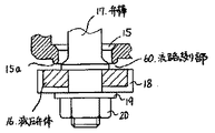
給水圧が設定圧よりも高い時に2次側を止水した場合、ダイヤフラム25が水圧によって上方に押圧移動され、減圧弁体16が減圧ポート15のシール部15aに密着し2次側の圧力が設定圧に保持される。この設定圧は、バネ圧調節ネジ23を回すことにより調節される。減圧弁体16が減圧ポート15のシール部15aに密着したときの状態を、図3に拡大して示す。この図からわかるように、シール時における弁棒17と減圧ポート15との隙間は、従来例に比べてかなり狭くしている。
【0016】
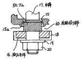
給水圧が設定圧よりも高い時に2次側を止水した後、2次側を通水した場合、ダイヤフラム25を押上げる圧力が下がり減圧弁体16が減圧ポート15のシール部15aより離れ、2次側の必要流量に応じた弁開口ストローク、すなわち通水断面積を確保した状態で安定する。そのときの状態を、図2に拡大して示す。図2に示すように、減圧ポート15にはテーパ状の段部が、また、対向する弁棒17にもほぼ同じテーパの段部が、それぞれ設けられている。このため、給水圧の変動によって生じる弁棒17の上下動による両部品の相対位置の変化に伴い、弁棒17と減圧ポート15との隙間で決まるこの部分の通水断面積が変化する。これを利用して、弁棒17と減圧ポート15との間で給水圧を減圧している。通水断面積は、給水圧が高いほど小さくなる。
【0017】
この第一実施例においては、上記したように、弁棒17と減圧ポート15との間で給水圧を減圧し、これにより、ダイヤフラム25を押上げる圧力を軽減させている。このため、安定状態においては、減圧ポート15のシール部15aと減圧弁体16との隙間(流路絞り部60)が大きくなるため、減圧ポート15と弁棒17の隙間を通過した異物が流路絞り部60に噛み込むことがない。
【0018】
図4は、本発明の第二実施例である減圧弁の構造を示す断面図であり、図5はその部分拡大図である。この例では、弁棒17に設けたテーパ状の段部をゴム50により被覆した点のみが第一実施例と異なり、他は同じである。ゴム50は、弁棒17に接着剤を塗布した後、焼付け成形しており、容易に剥がれることはない。
【0019】
この例でも、第一実施例と同様の効果を奏し、さらに万一、減圧ポート15と弁棒17のテーパ状の段部に異物が噛み込んだとしても、ゴム50が弾性変形して異物を吸収するため、弁棒17の摺動を妨げないという効果をも有する。
【図面の簡単な説明】
【図1】 本発明の第一実施例である減圧弁の構造を示す断面図
【図2】 図1の部分拡大図
【図3】 図1の部分拡大図
【図4】 本発明の第二実施例である減圧弁の構造を示す断面図
【図5】 図4の部分拡大図
【図6】 従来の減圧弁の構造を示す断面図
【図7】 図6の部分拡大図
【符号の説明】
11…流入ポート
12…ストレーナ
13…逆止弁
14…隔壁
15…減圧ポート
15a…シール部
16…減圧弁体
17…弁棒
17a…フランジ
18…弁体カバー
19…ワッシャー
20…ナット
21…減圧弁保持部
22…流出水圧調節バネ
23…バネ圧調節ネジ
24…バネカバー
25…ダイヤフラム
26…バネ設置室
27…バルブボディー
28…ナット
29…開口
30…Oリング
31…キャップ
32…流出ポート
50…ゴム
60…流路絞り部[0001]
BACKGROUND OF THE INVENTION
The present invention relates to a pressure reducing valve.
[0002]
[Prior art]
A conventional pressure reducing valve will be described with reference to FIGS. FIG. 6 is a sectional view showing the structure of a conventional pressure reducing valve, and FIG. 7 is a partially enlarged view thereof.
[0003]
Water passes from the inflow port 11 through the strainer 12, pushes up the check valve 13, and reaches the
[0004]
The outflow water pressure adjusting spring 22 is disposed in a spring installation chamber 26 surrounded by a spring cover 24 and a diaphragm 25. The outer periphery of the diaphragm 25 is held between the spring cover 24 and the valve body 27. The edge of the central opening of the diaphragm 25 is held between the flange 17 a of the
[0005]
When the secondary side is stopped when the water supply pressure is higher than the set pressure, the diaphragm 25 is pushed upward by the water pressure, the pressure reducing valve body 16 is brought into close contact with the
[0006]
When the water supply pressure is higher than the set pressure, when the secondary side is stopped and then the secondary side is passed, the pressure for pushing up the diaphragm 25 decreases and the pressure reducing valve body 16 is separated from the
[0007]
[Problems to be solved by the invention]
However, in the above-described conventional configuration, since the gap between the
[0008]
In this case, when the secondary side is stopped, the pressure reducing valve body 16 cannot completely adhere to the
[0009]
The present invention has been made to solve the above-described problems, and an object of the present invention is to provide a pressure reducing valve that can prevent the occurrence of a failure by preventing a foreign matter from being caught.
[0010]
[Means, actions and effects for solving the problems]
In order to achieve the above object, in claim 1, a
Therefore, the water flow cross-sectional area of this portion determined by the gap between the
[0011]
Further, the present invention is characterized in that the stepped portion provided on the
Therefore, even if foreign matter is caught in the tapered step portion of the
[0012]
DETAILED DESCRIPTION OF THE INVENTION
Embodiments of the present invention will be described below with reference to the accompanying drawings. FIG. 1 is a sectional view showing the structure of a pressure reducing valve according to a first embodiment of the present invention, and FIGS. 2 and 3 are partially enlarged views thereof.
[0013]
Water passes from the inflow port 11 through the strainer 12, pushes up the check valve 13, and reaches the
[0014]
The outflow water pressure adjusting spring 22 is disposed in a spring installation chamber 26 surrounded by a spring cover 24 and a diaphragm 25. The outer peripheral portion of the diaphragm 25 is sandwiched between the spring cover 24 and the valve body 27. The edge of the central opening of the diaphragm 25 is sandwiched between the flange 17a of the
[0015]
When the secondary side is stopped when the water supply pressure is higher than the set pressure, the diaphragm 25 is pushed upward by the water pressure, the pressure reducing valve body 16 is brought into close contact with the
[0016]
When the water supply pressure is higher than the set pressure, when the secondary side is stopped and then the secondary side is passed, the pressure for pushing up the diaphragm 25 decreases and the pressure reducing valve body 16 is separated from the
[0017]
In the first embodiment, as described above, the feed water pressure is reduced between the
[0018]
FIG. 4 is a sectional view showing the structure of a pressure reducing valve according to a second embodiment of the present invention, and FIG. 5 is a partially enlarged view thereof. This example differs from the first example only in that the tapered step provided on the
[0019]
In this example, the same effect as that of the first embodiment is obtained, and even if foreign matter is caught in the tapered step portions of the
[Brief description of the drawings]
1 is a sectional view showing the structure of a pressure reducing valve according to a first embodiment of the present invention. FIG. 2 is a partially enlarged view of FIG. 1. FIG. 3 is a partially enlarged view of FIG. FIG. 5 is a partially enlarged view of FIG. 4. FIG. 6 is a sectional view showing the structure of a conventional pressure reducing valve. FIG. 7 is a partially enlarged view of FIG. ]
DESCRIPTION OF SYMBOLS 11 ... Inflow port 12 ... Strainer 13 ... Check valve 14 ...
Claims (2)
減圧ポート(15)にテーパ状の段部を設けるとともに、該段部と略同テーパの段部を弁棒(17)にも設け、弁棒(17)の径は、段部から減圧弁体(16)の区間の径が段部よりダイヤフラム(25)側の径よりも太径となるように形成されており、
減圧弁体(16)が減圧ポート(15)のシール部(15a)に密着している状態では、弁棒(17)の段部より減圧弁体(16)側の太径の部分が減圧ポート(15)を貫通しており、
減圧弁体(16)が減圧ポート(15)のシール部(15a)から離れてから所定の間は、弁棒(17)の段部より減圧弁体(16)側の太径の部分が減圧ポート(15)を貫通した状態を継続し、その後、更に減圧弁体(16)が減圧ポート(15)のシール部(15a)から離れて停止した安定状態においては、弁棒(17)の段部よりダイヤフラム(25)側の部分が減圧ポート(15)を貫通し、減圧ポート(15)に設けられたテーパ状の段部と弁棒(17)の段部とが対向し、それにより、安定状態において、減圧ポート(15)に設けられたテーパ状の段部と弁棒(17)の段部とが対向した隙間より、流路絞り部(60)を形成している減圧ポート(15)のシール部(15a)と減圧弁体(16)との隙間の方が大きくなることを特徴とする減圧弁。A valve stem (17), the valve stem and outlet water pressure regulating spring for biasing the valve rod (17) attached to one end in the normally open direction (17) (22), valve stem (17) mounted valve on one end of Diaphragm ( 25 ) for urging rod ( 17 ) in the closing direction by water supply pressure, pressure reducing valve body ( 16 ) attached to the other end of valve rod ( 17 ) , partition wall separating primary side and secondary side a vacuum port provided at (14) (15), the sealing portion (15a) and a gap in which the flow path diaphragm portion of the pressure reducing valve body (16) (60) a pressure reducing valve provided with a pressure reducing port (15) ,
Provided with a tapered step portion to a vacuum port (15), also it provided a stepped portion of the stepped portion and substantially the same taper on the valve stem (17), the diameter of the valve stem (17), the vacuum valve body from the stepped portion The diameter of the section of ( 16 ) is formed so as to be larger than the diameter of the diaphragm ( 25 ) side from the stepped portion,
In a state where the pressure reducing valve body (16) is in close contact with the sealing portion of the vacuum port (15) (15a), a pressure reducing valve body (16) large-diameter portion of the side decompression port the step portion of the valve stem (17) ( 15 )
During the sealing portion away from the (15a) of a predetermined pressure reducing valve body (16) is vacuum port (15), valve stem (17) of the stepped portion from the pressure reducing valve body (16) large-diameter portion of the side vacuum In a stable state where the state of penetrating the port ( 15 ) is continued and then the pressure reducing valve body ( 16 ) is further moved away from the seal portion ( 15a ) of the pressure reducing port ( 15 ) , the stage of the valve stem ( 17 ) portion of the diaphragm (25) side through the vacuum port (15) than the parts, and the stepped portion of the valve stem and tapered step portion provided in the vacuum port (15) (17) face each other, whereby, in steady state, than the gap in which the step portion is opposed, vacuum forming passage aperture section (60) ports vacuum port (15) and tapered step portion provided on the valve stem (17) (15 seal portion) and (15a) a pressure reducing valve body (1 ) A pressure reducing valve, characterized in that towards the gap becomes large.
Priority Applications (1)
| Application Number | Priority Date | Filing Date | Title |
|---|---|---|---|
| JP2001036798A JP4666434B2 (en) | 2001-02-14 | 2001-02-14 | Pressure reducing valve |
Applications Claiming Priority (1)
| Application Number | Priority Date | Filing Date | Title |
|---|---|---|---|
| JP2001036798A JP4666434B2 (en) | 2001-02-14 | 2001-02-14 | Pressure reducing valve |
Publications (3)
| Publication Number | Publication Date |
|---|---|
| JP2002244742A JP2002244742A (en) | 2002-08-30 |
| JP2002244742A5 JP2002244742A5 (en) | 2008-01-10 |
| JP4666434B2 true JP4666434B2 (en) | 2011-04-06 |
Family
ID=18900024
Family Applications (1)
| Application Number | Title | Priority Date | Filing Date |
|---|---|---|---|
| JP2001036798A Expired - Lifetime JP4666434B2 (en) | 2001-02-14 | 2001-02-14 | Pressure reducing valve |
Country Status (1)
| Country | Link |
|---|---|
| JP (1) | JP4666434B2 (en) |
Families Citing this family (2)
| Publication number | Priority date | Publication date | Assignee | Title |
|---|---|---|---|---|
| JP4666434B2 (en) * | 2001-02-14 | 2011-04-06 | Toto株式会社 | Pressure reducing valve |
| US20080202604A1 (en) * | 2007-02-28 | 2008-08-28 | James Matthew Dalton | Apparatus to regulate fluid flow |
Citations (11)
| Publication number | Priority date | Publication date | Assignee | Title |
|---|---|---|---|---|
| JPS5259921U (en) * | 1975-10-30 | 1977-04-30 | ||
| JPS5960518A (en) * | 1982-09-30 | 1984-04-06 | Fushiman Kk | Pressure-reducing valve |
| JPS6065810U (en) * | 1983-10-07 | 1985-05-10 | フシマン株式会社 | pressure regulating valve |
| JPS62112712U (en) * | 1986-01-06 | 1987-07-17 | ||
| JPH02111815U (en) * | 1989-02-22 | 1990-09-06 | ||
| JPH0441174U (en) * | 1990-08-06 | 1992-04-08 | ||
| JPH0531770A (en) * | 1990-12-18 | 1993-02-09 | Maxell Seiki Kk | Injection molding system |
| JPH0566374A (en) * | 1991-09-06 | 1993-03-19 | Sony Corp | Liquid crystal display device |
| JPH0736550A (en) * | 1993-07-21 | 1995-02-07 | Ben:Kk | Pressure reducing valve |
| JPH10196821A (en) * | 1997-01-10 | 1998-07-31 | Nissan Motor Co Ltd | Pressure regulating valve structure |
| JP2002244742A (en) * | 2001-02-14 | 2002-08-30 | Toto Ltd | Pressure reducing valve |
-
2001
- 2001-02-14 JP JP2001036798A patent/JP4666434B2/en not_active Expired - Lifetime
Patent Citations (11)
| Publication number | Priority date | Publication date | Assignee | Title |
|---|---|---|---|---|
| JPS5259921U (en) * | 1975-10-30 | 1977-04-30 | ||
| JPS5960518A (en) * | 1982-09-30 | 1984-04-06 | Fushiman Kk | Pressure-reducing valve |
| JPS6065810U (en) * | 1983-10-07 | 1985-05-10 | フシマン株式会社 | pressure regulating valve |
| JPS62112712U (en) * | 1986-01-06 | 1987-07-17 | ||
| JPH02111815U (en) * | 1989-02-22 | 1990-09-06 | ||
| JPH0441174U (en) * | 1990-08-06 | 1992-04-08 | ||
| JPH0531770A (en) * | 1990-12-18 | 1993-02-09 | Maxell Seiki Kk | Injection molding system |
| JPH0566374A (en) * | 1991-09-06 | 1993-03-19 | Sony Corp | Liquid crystal display device |
| JPH0736550A (en) * | 1993-07-21 | 1995-02-07 | Ben:Kk | Pressure reducing valve |
| JPH10196821A (en) * | 1997-01-10 | 1998-07-31 | Nissan Motor Co Ltd | Pressure regulating valve structure |
| JP2002244742A (en) * | 2001-02-14 | 2002-08-30 | Toto Ltd | Pressure reducing valve |
Also Published As
| Publication number | Publication date |
|---|---|
| JP2002244742A (en) | 2002-08-30 |
Similar Documents
| Publication | Publication Date | Title |
|---|---|---|
| US9098092B2 (en) | Balanced valve cartridge | |
| US20100012197A1 (en) | Automatic water diverter | |
| US7140590B2 (en) | Pinch valve element for plumbing fixture flush valve | |
| US20050189506A1 (en) | Low flow valve improvement | |
| US9964963B2 (en) | Pressure equalizing insert | |
| US20090260699A1 (en) | Throttling structure for use in a fluid pressure device | |
| US4662395A (en) | Pressurized liquid flushing valve arrangement with a shut-off sleeve | |
| US4314582A (en) | Combined pressure-regulator and manual shut-off valve | |
| JP4666434B2 (en) | Pressure reducing valve | |
| JP2002089722A (en) | Pressure control valve | |
| CA2637121A1 (en) | Automatic water diverter | |
| JP7180465B2 (en) | Relief valve integrated pressure reducing valve and water heater | |
| JPH0237509B2 (en) | ||
| US4345619A (en) | Backflow preventer | |
| JP4738078B2 (en) | Pilot flow control device | |
| JPH0942489A (en) | Ball valve having check valve | |
| JP2002132351A (en) | Pressure reducing valve | |
| US20190292755A1 (en) | Adjustable drain valve for dry barrel fire hydrant | |
| JP2551381Y2 (en) | Pressure reducing valve | |
| JP2002207517A (en) | Pressure reducing valve | |
| KR200448694Y1 (en) | Complex set fluid valve | |
| CN210770256U (en) | Double-speed adjustable diaphragm type water pump control valve | |
| JP7050385B2 (en) | Pressure reducing valve | |
| KR940015335A (en) | Check valve in constant flow | |
| KR200368321Y1 (en) | Pressure reducing valve for a water supply |
Legal Events
| Date | Code | Title | Description |
|---|---|---|---|
| A521 | Written amendment |
Free format text: JAPANESE INTERMEDIATE CODE: A523 Effective date: 20071018 |
|
| A621 | Written request for application examination |
Free format text: JAPANESE INTERMEDIATE CODE: A621 Effective date: 20071018 |
|
| A521 | Written amendment |
Free format text: JAPANESE INTERMEDIATE CODE: A821 Effective date: 20071019 |
|
| A977 | Report on retrieval |
Free format text: JAPANESE INTERMEDIATE CODE: A971007 Effective date: 20091106 |
|
| A131 | Notification of reasons for refusal |
Free format text: JAPANESE INTERMEDIATE CODE: A131 Effective date: 20091116 |
|
| A521 | Written amendment |
Free format text: JAPANESE INTERMEDIATE CODE: A523 Effective date: 20100115 |
|
| A521 | Written amendment |
Free format text: JAPANESE INTERMEDIATE CODE: A821 Effective date: 20100119 |
|
| A521 | Written amendment |
Free format text: JAPANESE INTERMEDIATE CODE: A523 Effective date: 20100317 |
|
| A131 | Notification of reasons for refusal |
Free format text: JAPANESE INTERMEDIATE CODE: A131 Effective date: 20100607 |
|
| A521 | Written amendment |
Free format text: JAPANESE INTERMEDIATE CODE: A523 Effective date: 20100804 |
|
| A521 | Written amendment |
Free format text: JAPANESE INTERMEDIATE CODE: A523 Effective date: 20100809 |
|
| A521 | Written amendment |
Free format text: JAPANESE INTERMEDIATE CODE: A523 Effective date: 20100908 |
|
| TRDD | Decision of grant or rejection written | ||
| A01 | Written decision to grant a patent or to grant a registration (utility model) |
Free format text: JAPANESE INTERMEDIATE CODE: A01 Effective date: 20110106 |
|
| A01 | Written decision to grant a patent or to grant a registration (utility model) |
Free format text: JAPANESE INTERMEDIATE CODE: A01 |
|
| A61 | First payment of annual fees (during grant procedure) |
Free format text: JAPANESE INTERMEDIATE CODE: A61 Effective date: 20110106 |
|
| FPAY | Renewal fee payment (event date is renewal date of database) |
Free format text: PAYMENT UNTIL: 20140121 Year of fee payment: 3 |
|
| R150 | Certificate of patent or registration of utility model |
Ref document number: 4666434 Country of ref document: JP Free format text: JAPANESE INTERMEDIATE CODE: R150 Free format text: JAPANESE INTERMEDIATE CODE: R150 |
|
| R250 | Receipt of annual fees |
Free format text: JAPANESE INTERMEDIATE CODE: R250 |
|
| R250 | Receipt of annual fees |
Free format text: JAPANESE INTERMEDIATE CODE: R250 |
|
| R250 | Receipt of annual fees |
Free format text: JAPANESE INTERMEDIATE CODE: R250 |
|
| R250 | Receipt of annual fees |
Free format text: JAPANESE INTERMEDIATE CODE: R250 |
|
| R250 | Receipt of annual fees |
Free format text: JAPANESE INTERMEDIATE CODE: R250 |
|
| R250 | Receipt of annual fees |
Free format text: JAPANESE INTERMEDIATE CODE: R250 |
|
| R250 | Receipt of annual fees |
Free format text: JAPANESE INTERMEDIATE CODE: R250 |
|
| R250 | Receipt of annual fees |
Free format text: JAPANESE INTERMEDIATE CODE: R250 |
|
| EXPY | Cancellation because of completion of term |