JP4664643B2 - Molding method for plastic products - Google Patents
Molding method for plastic products Download PDFInfo
- Publication number
- JP4664643B2 JP4664643B2 JP2004290364A JP2004290364A JP4664643B2 JP 4664643 B2 JP4664643 B2 JP 4664643B2 JP 2004290364 A JP2004290364 A JP 2004290364A JP 2004290364 A JP2004290364 A JP 2004290364A JP 4664643 B2 JP4664643 B2 JP 4664643B2
- Authority
- JP
- Japan
- Prior art keywords
- molded product
- outer edge
- corner
- molding
- weld
- Prior art date
- Legal status (The legal status is an assumption and is not a legal conclusion. Google has not performed a legal analysis and makes no representation as to the accuracy of the status listed.)
- Active
Links
Images

Landscapes
- Moulds For Moulding Plastics Or The Like (AREA)
Description
本発明は、プラスチック製品の成形方法に関し、より詳しくは、スライドコアを有する射出成形機を用いたプラスチック製品の成形方法に関する。 The present invention relates to a plastic product molding method, and more particularly to a plastic product molding method using an injection molding machine having a slide core.
プラスチック製品の成形方法として最も一般的な射出成形法を用いた場合、樹脂流れの合流部位でウエルドと呼ばれる部位がほとんど不可避的に生じる。特に成形品のうち、射出ゲートから離れた部位は、温度の低くなった樹脂流れの合流点となり、当該ウエルド部位は、ウエルドラインと呼ばれる筋として成形品表面に明確に現れる。かかるウエルドラインは射出成形では不可避であるため、ウエルドラインを目立たない位置に発生させるように射出ゲート位置を工夫したり、ウエルドライン位置を過熱したりして、目立たなくする工夫がなされている。 When the most common injection molding method is used as a molding method for plastic products, a portion called a weld is almost inevitably generated at a joining portion of resin flows. In particular, a portion of the molded product that is away from the injection gate becomes a confluence of the resin flow at a low temperature, and the weld portion clearly appears on the surface of the molded product as a line called a weld line. Since such a weld line is unavoidable in the injection molding, an idea is made to make the injection gate position inconspicuous by devising the injection gate position so that the weld line is generated in an inconspicuous position or by overheating the weld line position.
このような技術により、ウエルドラインできるだけ目立たなくすることができるが、かかる処理をしても、ウエルドライン付近の樹脂流れの合流を回避しえたわけではない。この点、特にメタリックな色彩を有する樹脂成形品では、かかる樹脂流れ方向が外観上明確に認識しやすいものである。例えば、成形品に光を当てた場合、かかるウエルド部分では、光の乱反射が生じるため、成形品のウエルド部分が縞模様に見えたり、さらには虹色に見えたりする場合もある。 With such a technique, the weld line can be made as inconspicuous as possible. However, even if such a process is performed, the joining of the resin flows in the vicinity of the weld line cannot be avoided. In this regard, particularly in a resin molded product having a metallic color, the resin flow direction is easily clearly recognized in appearance. For example, when light is applied to a molded product, irregular reflection of light occurs in such a weld portion, so that the weld portion of the molded product may appear to be a striped pattern, or may appear to be iridescent.
かかるウエルドは、樹脂流れの流れによって生じるので、平面的・曲面的な形状、すなわち平坦な形状であるほうがかかる樹脂流れの影響が少なく、目立ちにくいものとなる。そこで特に孔を有する部材ボス部と呼ばれる突出部を有するプラスチック製品の成形においては、平面的な形状を一旦成形した直後に、引き続いて当該孔やボス部を形成するピンを移動させることにより、当該孔やボス部を成形する方法がある(例えばボス部を有する成形品の製造方法として、特許文献1)。当該方法によれば、孔やボス部付近で発生するウエルドの発生を抑えることができる。
しかし、孔やボス部のない平坦な形状であっても、成形品が箱形状や多角形の板形状など、その外縁に角を有する形状の場合、当該角部分で樹脂流れの合流や乱れが生じるので、成形品の表面にウエルドとなって表面に現れる。このため商品とした場合、デザイン上の問題があった。 However, even if it is a flat shape without holes or bosses, if the molded product has a corner on its outer edge, such as a box shape or a polygonal plate shape, the resin flow may merge or be disturbed at the corner portion. As a result, it appears as a weld on the surface of the molded product. For this reason, when it was made into a product, there was a problem in design.
上記問題の解決方法として、2次元的な板形状の成形品を大量に製造する場合であれば、大きな一枚板を成形し、後から適度の大きさに打ち抜く方法が考えられる。しかし、かかる成形法は箱形状のような立体的な形状の成形には不適である。また工程が増加するため、同形状品を大量に製造する場合で無いかぎり、コスト的な面から現実的な方法ではない。 As a method for solving the above problem, if a large number of two-dimensional plate-shaped molded products are manufactured, a method of forming a large single plate and punching it into an appropriate size later can be considered. However, such a forming method is not suitable for forming a three-dimensional shape such as a box shape. In addition, since the number of processes is increased, it is not a practical method from the viewpoint of cost unless the same-shaped product is manufactured in large quantities.
更に、ウエルドラインのない長方形箱型形状の成形品の製造方法として、樹脂溶融物射出後キャビティ内を圧縮する射出圧縮成形機による成形方法がある(例えば、特許文献2)。しかし射出圧縮成形機の初期導入費用が高く、またランニングコストが通常の射出成形機よりも高いため、安価な成形品への応用は現実的ではなかった。
本発明では、上記現状を鑑みて、プラスチック製品が、外縁部に角を有する成形品の場合の成形方法として、当該角部分にウエルドが生じない、少量製造でも経済的な成形方法を提供することを課題とする。 In the present invention, in view of the above-mentioned present situation, as a molding method in the case where a plastic product is a molded product having a corner at an outer edge portion, an economical molding method is provided even in a small amount of production in which no weld occurs in the corner portion. Is an issue.
本発明者は鋭意検討した結果、プラスチック製品の成形方法において、外縁部に角を有する成形品を成形する方法として、スライドコアを有する射出成形機を用いて、前記成形品を成形する際に、前記外縁部を延長して切り取り部を設ける射出成形工程と、前記射出成形工程後であって前記成形品取出し前若しくは前記成形品取出しと同時に、前記スライドコアの移動により、前記切り取り部を削除する工程とを少なくとも有する成形方法とすることを主要な手段とすることで、上記課題を解決した。 As a result of intensive studies, the present inventors have determined that when molding the molded product using an injection molding machine having a slide core as a method of molding a molded product having a corner at the outer edge in the plastic product molding method, An injection molding step in which the outer edge portion is extended to provide a cut-out portion, and the cut-out portion is deleted by the movement of the slide core after the injection molding step and before or simultaneously with the removal of the molded product. The above-described problems have been solved by using a molding method having at least a process as a main means.
すなわち、本来角の周辺に発生するウエルドを、成形品の外縁部から延長して設けられた切り取り部に発生させて、これを削除することにより、成形品にはウエルドが残らないようにしたものである。 In other words, the weld that originally occurs around the corner is generated in the cut-out portion provided extending from the outer edge of the molded product, and this is deleted so that no weld remains in the molded product. It is.
本発明の成形方法によれば、外縁部に角のある成形品について、射出成形後に複雑な工程を経ることなく、ウエルドの無い成形品を経済的な方法で得ることができる。 According to the molding method of the present invention, it is possible to obtain a molded product having no weld with an economical method without going through a complicated process after injection molding for a molded product having a corner at the outer edge.
以下図面を用いて説明するが、本発明の様態は、図面で示した様態に限られるものではない。 The present invention will be described below with reference to the drawings, but the embodiments of the present invention are not limited to the embodiments shown in the drawings.
本発明の成形方法に用いることができる樹脂は、射出成形にて成形できる樹脂であれば、特に制限されない。なかでも熱可塑性樹脂を好適に使用できる。溶融温度、射出速度等の成形条件は、樹脂の溶融温度や粘度(分子数)などの性質により適正な範囲が異なるが、公知の成形条件を用いることができる。 The resin that can be used in the molding method of the present invention is not particularly limited as long as it is a resin that can be molded by injection molding. Among these, a thermoplastic resin can be preferably used. The molding conditions such as the melting temperature and the injection speed vary depending on properties such as the melting temperature and viscosity (number of molecules) of the resin, but known molding conditions can be used.
特に本発明の成形方法が有用となるのは、メタリック色のプラスチック製品を製造するために、樹脂中にアルミニウムフレークのような金属フレークや金属粉を含有した場合である。この場合、金属フレークや粉が樹脂流れに沿って配向するため、ウエルドがより目立ちやすい。さらに光沢のあるメタリック色の場合、光の乱反射による外観上の影響が大きい。かかる理由から、メタリック色のプラスチック製品を製造する場合には、外観より明確に認識できるウエルドラインのみならず、その近傍におけるウエルドの影響も除去する必要がある。 In particular, the molding method of the present invention is useful when a resin contains metal flakes such as aluminum flakes or metal powder in order to produce a metallic plastic product. In this case, since the metal flakes and powders are oriented along the resin flow, the weld is more conspicuous. Further, in the case of a glossy metallic color, the influence on the appearance due to irregular reflection of light is large. For this reason, when manufacturing a metallic plastic product, it is necessary to remove not only the weld line that can be clearly recognized from the appearance, but also the influence of the weld in the vicinity thereof.
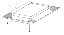
本発明の成形方法にて得られる成形品1の形状は、平面的な形状でも立体的な形状でも良いが、その外縁部に角2がある形状のものである。本発明は角を有する成形品1であっても、当該角の周辺にウエルドの影響の無いプラスチック製品を得るための方法だからである。本発明にいう外縁部の角とは、外縁部のうち、二直角(180度)未満の角度(鋭角、垂直、鈍角)で折れ曲がっている部位をいう。このような角2を有する形状の例としては、図1に示したような長方形などの多角形の底面を有する柱形状や、多角形の板形状などがある。多角形形状の以外にも、例えば星型形状のような形状でも外縁部に角2を有する形状である。またスライドコアの移動が通常直線移動であることを考慮すれば、本発明の角を有する成形品の形状は、両底面または各側面の少なくともいずれかには、ボス部のような突起や凹み、更にはねじれなど、スライドコアの直線移動に支障となるものが無い形状が好ましい。
The shape of the molded product 1 obtained by the molding method of the present invention may be a planar shape or a three-dimensional shape, but is a shape having a
(射出成形工程)
本発明の成形方法における射出成形工程では、射出ゲート4から樹脂溶融物を射出し、外縁部に角2を有する成形品1を成形する際に、当該外縁部の外縁をさらに延長して成形し、後から成形品1から削除されることになる切り取り部3を同時に成形する。図1は、本発明の成形方法において、切り取り部3を設けた成形品1を成形した様子を模式的に示した図である。外縁部を延長して設ける切り出し部は、必ずしも外縁をそのまま延長した方向に延長されている必要は無い。むしろ図1のように外縁の方向に対して垂直方向に延長されていることが好ましい。かかる方向に切り出し部を設けると、後述のスライドコアによる切り取り部3の切断が容易となり、また切り取り部3削除後の成形品1の切り取り部跡の処理も容易となるからである。
(Injection molding process)
In the injection molding step of the molding method of the present invention, when the resin melt is injected from the injection gate 4 and the molded product 1 having the
この切り取り部3は、図1ではウエルド発生部として斜線にて表したように、本来成形品1の外縁部の角2の周辺に発生するはずのウエルドを当該角2周辺から逃がして、発生させる部分である。従って、切り取り部3は角2の部分から更に外側に延長して設けられるものである。言い換えれば、切り出し部の位置は、射出ゲート4からみて、外縁部の角2の位置よりも、さらに遠方に設けられることになる。
As shown in FIG. 1 by hatching as the weld generation portion in FIG. 1, the
切り取り部3の大きさや形状は、当該切り取り部3にウエルドが発生して、成形品外縁部の角2周辺にその影響が無い程度に大きいものであれば、適宜定めることができる。切り出し分の大きさをどの程度にするかは、実験的に決めることもできるし、流体力学の計算から理論的に決めることもできる。
The size and shape of the cut-out
(切り取り部削除工程)
本発明の成形方法に用いる射出成形機は、コア部が移動するスライドコアを有するものであることが必要である。スライドコアの移動により、切り取り部3を削除するからである。スライドコアを有する射出成形機は、公知の機械である。スライドコアの移動による切り取り部3の削除は、成形品1成形後、型開き前或いは型開きと同時に行う。樹脂の種類後とのスライドコアが移動開始する際の成形品1の温度やスライドコアの移動速度等の条件を適宜調整することにより、成形品1の切り取り部跡を目立たなくでき、或いは後の処理が容易になる。図2は図1の状態からスライドコアが移動して、切り取り部3が成形品1から削除される途中の様子を模式的に示した図である。図2の様態では、スライドコアが下方に移動することにより、成形品1も下方に移動し、切り取り部3だけが元の位置に残されることにより、成形品1から削除されるものである。
(Cut part deletion process)
The injection molding machine used for the molding method of the present invention needs to have a slide core on which the core part moves. This is because the
かかる工程を経て得られる外縁部に角2を有する成形品1は、ウエルドの影響が現れない。よって、プラスチック製品としてデザイン上好ましいものが得られる。なお、外縁部に角を有し、ボス部や孔を合わせて有する成形品の場合は、本発明の成形方法に加えて、上記従来の技術の欄で説明したボス部や孔周辺のウエルド除去方法も合わせて使用することができる。
In the molded product 1 having the
本発明の成形方法は、その表面にウエルドのないプラスチック製品を成形する方法として、幅広く利用できる。 The molding method of the present invention can be widely used as a method of molding a plastic product having no weld on the surface thereof.
1 成形品
2 成形品外縁部の角
3 切り取り部
4 ウエルド発生部
5 射出ゲート
DESCRIPTION OF SYMBOLS 1 Molded
Claims (2)
中央上側の射出ゲートから樹脂溶融物を射出し、外縁部に角を有する成形品を成形する際に、当該外縁部の外縁を該外縁の方向に対して垂直方向に当該外縁部の角の位置よりもさらに延長して、切り取り部を成形し、
前記切り取り部にウエルドを前記角周辺から逃がして発生させる射出成形工程と、
前記射出成形工程後であって、前記成形品取出し前若しくは前記成形品取出しと同時に、前記スライドコアの移動により、前記成形品も移動し、切り取り部だけが元の位置に残されて、前記切り取り部を削除する工程とを少なくとも有するプラスチック製品の成形方法。 A plastic product molding method for molding a molded product having a corner at an outer edge by an injection molding machine having a slide core,
When the resin melt is injected from the center upper injection gate to form a molded product having a corner at the outer edge, the outer edge of the outer edge is positioned perpendicular to the direction of the outer edge. To extend further, to shape the cutout,
An injection molding process for generating a weld from the periphery of the corner in the cut portion ; and
After the injection molding process, before the molded product is taken out or at the same time as the molded product is taken out, the molded product is also moved by the movement of the slide core, and only the cut portion is left in the original position. A method of molding a plastic product, comprising at least a step of deleting a part.
Priority Applications (1)
| Application Number | Priority Date | Filing Date | Title |
|---|---|---|---|
| JP2004290364A JP4664643B2 (en) | 2004-10-01 | 2004-10-01 | Molding method for plastic products |
Applications Claiming Priority (1)
| Application Number | Priority Date | Filing Date | Title |
|---|---|---|---|
| JP2004290364A JP4664643B2 (en) | 2004-10-01 | 2004-10-01 | Molding method for plastic products |
Publications (2)
| Publication Number | Publication Date |
|---|---|
| JP2006103052A JP2006103052A (en) | 2006-04-20 |
| JP4664643B2 true JP4664643B2 (en) | 2011-04-06 |
Family
ID=36373307
Family Applications (1)
| Application Number | Title | Priority Date | Filing Date |
|---|---|---|---|
| JP2004290364A Active JP4664643B2 (en) | 2004-10-01 | 2004-10-01 | Molding method for plastic products |
Country Status (1)
| Country | Link |
|---|---|
| JP (1) | JP4664643B2 (en) |
Citations (1)
| Publication number | Priority date | Publication date | Assignee | Title |
|---|---|---|---|---|
| JPS59107223U (en) * | 1983-01-10 | 1984-07-19 | トーワ株式会社 | Mold equipment for resin molding of circular resin molded products |
-
2004
- 2004-10-01 JP JP2004290364A patent/JP4664643B2/en active Active
Patent Citations (1)
| Publication number | Priority date | Publication date | Assignee | Title |
|---|---|---|---|---|
| JPS59107223U (en) * | 1983-01-10 | 1984-07-19 | トーワ株式会社 | Mold equipment for resin molding of circular resin molded products |
Also Published As
| Publication number | Publication date |
|---|---|
| JP2006103052A (en) | 2006-04-20 |
Similar Documents
| Publication | Publication Date | Title |
|---|---|---|
| JP5724574B2 (en) | Manufacturing method of injection molded products | |
| JP2000108167A (en) | Resin molded article having aperture holes and manufacture thereof | |
| JP5006881B2 (en) | Injection molds and molded products | |
| JP2739279B2 (en) | Molding method for electronic components mounted on a substrate | |
| JP4664643B2 (en) | Molding method for plastic products | |
| JP2009214532A (en) | Resin molded component and its manufacturing process | |
| CN102166811A (en) | Mold for injection molding | |
| CN108621366A (en) | Integral formation method and Integral molding device for insoles | |
| JP2011005743A5 (en) | ||
| JP2008188855A (en) | Injection molding mold and injection molding method using the injection molding mold | |
| JP6422729B2 (en) | Plastic molded product | |
| JP2012017135A (en) | Case and its manufacturing method | |
| KR200394900Y1 (en) | Injection molding machaine having a needle gate | |
| JP6400401B2 (en) | Mold for molding and molding method | |
| JP6851232B2 (en) | Resin injection molded product, casing for power tools using this resin injection molded product | |
| JP6880395B2 (en) | Manufacturing method of injection molded product | |
| JP6930812B2 (en) | Manufacturing method of workpieces with holes | |
| JPH07276410A (en) | Injection molding | |
| CN214687680U (en) | Advance gluey structure and contain its mould | |
| JP5927573B2 (en) | Plate-like casing member and injection molding method thereof | |
| JP2003053792A (en) | Injection-molded article and injection mold | |
| JP6363491B2 (en) | Vehicle parts and manufacturing method thereof | |
| JP5687523B2 (en) | Resin molded product and display device | |
| JP6382591B2 (en) | Manufacturing method of resin molded products | |
| JP2015182400A (en) | Metal mold for injection molding, and method for production of resin molded article using the same |
Legal Events
| Date | Code | Title | Description |
|---|---|---|---|
| A621 | Written request for application examination |
Free format text: JAPANESE INTERMEDIATE CODE: A621 Effective date: 20070907 |
|
| RD04 | Notification of resignation of power of attorney |
Free format text: JAPANESE INTERMEDIATE CODE: A7424 Effective date: 20071212 |
|
| A977 | Report on retrieval |
Free format text: JAPANESE INTERMEDIATE CODE: A971007 Effective date: 20100331 |
|
| A131 | Notification of reasons for refusal |
Free format text: JAPANESE INTERMEDIATE CODE: A131 Effective date: 20100402 |
|
| A521 | Request for written amendment filed |
Free format text: JAPANESE INTERMEDIATE CODE: A523 Effective date: 20100601 |
|
| TRDD | Decision of grant or rejection written | ||
| A01 | Written decision to grant a patent or to grant a registration (utility model) |
Free format text: JAPANESE INTERMEDIATE CODE: A01 Effective date: 20101213 |
|
| A01 | Written decision to grant a patent or to grant a registration (utility model) |
Free format text: JAPANESE INTERMEDIATE CODE: A01 |
|
| A61 | First payment of annual fees (during grant procedure) |
Free format text: JAPANESE INTERMEDIATE CODE: A61 Effective date: 20110107 |
|
| R150 | Certificate of patent or registration of utility model |
Ref document number: 4664643 Country of ref document: JP Free format text: JAPANESE INTERMEDIATE CODE: R150 Free format text: JAPANESE INTERMEDIATE CODE: R150 |
|
| FPAY | Renewal fee payment (event date is renewal date of database) |
Free format text: PAYMENT UNTIL: 20140114 Year of fee payment: 3 |
|
| R250 | Receipt of annual fees |
Free format text: JAPANESE INTERMEDIATE CODE: R250 |
|
| S531 | Written request for registration of change of domicile |
Free format text: JAPANESE INTERMEDIATE CODE: R313531 |
|
| R350 | Written notification of registration of transfer |
Free format text: JAPANESE INTERMEDIATE CODE: R350 |
|
| R250 | Receipt of annual fees |
Free format text: JAPANESE INTERMEDIATE CODE: R250 |
|
| R250 | Receipt of annual fees |
Free format text: JAPANESE INTERMEDIATE CODE: R250 |
|
| R250 | Receipt of annual fees |
Free format text: JAPANESE INTERMEDIATE CODE: R250 |
|
| R250 | Receipt of annual fees |
Free format text: JAPANESE INTERMEDIATE CODE: R250 |
|
| R250 | Receipt of annual fees |
Free format text: JAPANESE INTERMEDIATE CODE: R250 |
|
| R250 | Receipt of annual fees |
Free format text: JAPANESE INTERMEDIATE CODE: R250 |
|
| R250 | Receipt of annual fees |
Free format text: JAPANESE INTERMEDIATE CODE: R250 |