JP4664045B2 - Regenerator and cryogenic refrigerator using the same - Google Patents
Regenerator and cryogenic refrigerator using the same Download PDFInfo
- Publication number
- JP4664045B2 JP4664045B2 JP2004323632A JP2004323632A JP4664045B2 JP 4664045 B2 JP4664045 B2 JP 4664045B2 JP 2004323632 A JP2004323632 A JP 2004323632A JP 2004323632 A JP2004323632 A JP 2004323632A JP 4664045 B2 JP4664045 B2 JP 4664045B2
- Authority
- JP
- Japan
- Prior art keywords
- working gas
- storage material
- sliding shaft
- heat storage
- cryogenic refrigerator
- Prior art date
- Legal status (The legal status is an assumption and is not a legal conclusion. Google has not performed a legal analysis and makes no representation as to the accuracy of the status listed.)
- Expired - Fee Related
Links
Images


Classifications
-
- F—MECHANICAL ENGINEERING; LIGHTING; HEATING; WEAPONS; BLASTING
- F25—REFRIGERATION OR COOLING; COMBINED HEATING AND REFRIGERATION SYSTEMS; HEAT PUMP SYSTEMS; MANUFACTURE OR STORAGE OF ICE; LIQUEFACTION SOLIDIFICATION OF GASES
- F25B—REFRIGERATION MACHINES, PLANTS OR SYSTEMS; COMBINED HEATING AND REFRIGERATION SYSTEMS; HEAT PUMP SYSTEMS
- F25B9/00—Compression machines, plants or systems, in which the refrigerant is air or other gas of low boiling point
- F25B9/14—Compression machines, plants or systems, in which the refrigerant is air or other gas of low boiling point characterised by the cycle used, e.g. Stirling cycle
-
- F—MECHANICAL ENGINEERING; LIGHTING; HEATING; WEAPONS; BLASTING
- F25—REFRIGERATION OR COOLING; COMBINED HEATING AND REFRIGERATION SYSTEMS; HEAT PUMP SYSTEMS; MANUFACTURE OR STORAGE OF ICE; LIQUEFACTION SOLIDIFICATION OF GASES
- F25B—REFRIGERATION MACHINES, PLANTS OR SYSTEMS; COMBINED HEATING AND REFRIGERATION SYSTEMS; HEAT PUMP SYSTEMS
- F25B2309/00—Gas cycle refrigeration machines
- F25B2309/001—Gas cycle refrigeration machines with a linear configuration or a linear motor
-
- F—MECHANICAL ENGINEERING; LIGHTING; HEATING; WEAPONS; BLASTING
- F25—REFRIGERATION OR COOLING; COMBINED HEATING AND REFRIGERATION SYSTEMS; HEAT PUMP SYSTEMS; MANUFACTURE OR STORAGE OF ICE; LIQUEFACTION SOLIDIFICATION OF GASES
- F25B—REFRIGERATION MACHINES, PLANTS OR SYSTEMS; COMBINED HEATING AND REFRIGERATION SYSTEMS; HEAT PUMP SYSTEMS
- F25B2309/00—Gas cycle refrigeration machines
- F25B2309/003—Gas cycle refrigeration machines characterised by construction or composition of the regenerator
-
- F—MECHANICAL ENGINEERING; LIGHTING; HEATING; WEAPONS; BLASTING
- F25—REFRIGERATION OR COOLING; COMBINED HEATING AND REFRIGERATION SYSTEMS; HEAT PUMP SYSTEMS; MANUFACTURE OR STORAGE OF ICE; LIQUEFACTION SOLIDIFICATION OF GASES
- F25B—REFRIGERATION MACHINES, PLANTS OR SYSTEMS; COMBINED HEATING AND REFRIGERATION SYSTEMS; HEAT PUMP SYSTEMS
- F25B2309/00—Gas cycle refrigeration machines
- F25B2309/14—Compression machines, plants or systems characterised by the cycle used
- F25B2309/1415—Pulse-tube cycles characterised by regenerator details
Landscapes
- Engineering & Computer Science (AREA)
- Physics & Mathematics (AREA)
- Mechanical Engineering (AREA)
- Thermal Sciences (AREA)
- General Engineering & Computer Science (AREA)
- Compressors, Vaccum Pumps And Other Relevant Systems (AREA)
- Pistons, Piston Rings, And Cylinders (AREA)
- Containers, Films, And Cooling For Superconductive Devices (AREA)
- Thermal Insulation (AREA)
Description
本発明は、再生機及びこれを適用した極低温冷凍機に係るもので、詳しくは、作動ガスに含まれた熱を蓄積し、該蓄積された熱を作動ガスに伝達する再生性能を高めるだけでなく、重さを最小化できる再生機及びこれを適用した極低温冷凍機に関するものである。 The present invention relates to a regenerator and a cryogenic refrigerator to which the regenerator is applied. Specifically, the present invention only accumulates the heat contained in the working gas and only enhances the regenerating performance of transmitting the accumulated heat to the working gas. In addition, the present invention relates to a regenerator capable of minimizing the weight and a cryogenic refrigerator to which the regenerator is applied.
一般に、小型電子部品及び超伝導体などの冷却のために、極低温冷凍機が使用されるが、前記極低温冷凍機には、スターリング冷凍機及びパルス管冷凍機などがある。 Generally, a cryogenic refrigerator is used for cooling small electronic components and superconductors, and examples of the cryogenic refrigerator include a Stirling refrigerator and a pulse tube refrigerator.
前記極低温冷凍機は、電気エネルギーを運動エネルギーに転換して作動ガスを圧縮させながら熱を発生する高温部と、前記圧縮される作動ガスのパルス差によって作動ガスを膨脹させながら外部の熱を吸収して急速に冷凍される冷凍部と、を含んで構成される。また、前記高温部及び冷凍部には、作動ガスが往来する流路が形成され、該流路には、作動ガスとの熱交換を行う蓄熱材を含む再生機が装着される。 The cryogenic refrigerator converts the electric energy into kinetic energy to generate heat while compressing the working gas, and external heat while expanding the working gas by the pulse difference between the compressed working gas. And a freezing part that is absorbed and rapidly frozen. The high-temperature part and the freezing part are formed with a flow path through which the working gas flows, and a regenerator including a heat storage material that exchanges heat with the working gas is attached to the flow path.
即ち、作動ガスが高温部から冷凍部に流動する過程で、該作動ガスに含まれた熱が再生機に吸収されることで、該作動ガスが相対的に低温状態で冷凍部に流動し、且つ、作動ガスが冷凍部から高温部に流動する過程で、該作動ガスが再生機に吸収された熱を受けて相対的に高温状態で高温部に流動する。 That is, in the process in which the working gas flows from the high temperature part to the freezing part, the heat contained in the working gas is absorbed by the regenerator so that the working gas flows to the freezing part at a relatively low temperature state, In the process where the working gas flows from the refrigeration part to the high temperature part, the working gas receives heat absorbed by the regenerator and flows to the high temperature part in a relatively high temperature state.
従って、前記再生機は、作動ガスが高温部から冷凍部に流動するとき、該作動ガスに含まれた熱を最大限に吸収すべきであり、且つ、作動ガスが冷凍部から高温部に流動するとき、該作動ガスに熱を最大限に伝達すべきである。これによって、前記再生機の効率が決定されるが、再生機の効率は、極低温冷凍機の効率に大きな影響を及ぼす。 Therefore, when the working gas flows from the high temperature part to the freezing part, the regenerator should absorb the heat contained in the working gas to the maximum extent, and the working gas flows from the freezing part to the high temperature part. When doing so, heat should be maximally transferred to the working gas. This determines the efficiency of the regenerator, but the efficiency of the regenerator greatly affects the efficiency of the cryogenic refrigerator.
一方、前記再生機の熱交換効率を高めるために、多くの研究が行なわれている。再生機の蓄熱材には、細い穴を有するメッシュを複数個積層した積層体を使用するか、または微細なステンレス繊維を固めたステンレス綿を圧着して使用する。そのうち、ステンレス綿は、メッシュ積層体よりも効率が高いため多く使用される。 On the other hand, many studies have been conducted to increase the heat exchange efficiency of the regenerator. As the heat storage material of the regenerator, a laminated body in which a plurality of meshes having thin holes are laminated is used, or stainless cotton in which fine stainless fibers are hardened is pressed and used. Of these, stainless steel is often used because it is more efficient than a mesh laminate.
然るに、従来のステンレス綿やメッシュ積層体が適用された再生機は、非常に重いという短所がある。一般に、極低温冷凍機は、作動中、冷凍部で極低温状態になって全ての潤滑油が凍るため、潤滑油は使用されず、ガスベアリングが使用される。よって、前記極低温冷凍機で再生機が相対運動をする場合、該再生機が重くなると、再生機及び該再生機と相対運動をする部品に摩耗が発生し、信頼性が低下するだけでなく、作動エネルギーが多く消耗されるという不都合な点があった。 However, a conventional regenerator to which stainless steel cotton or a mesh laminate is applied has a disadvantage that it is very heavy. In general, the cryogenic refrigerator is in a cryogenic state in the refrigeration unit during operation and all the lubricating oil is frozen, so that the lubricating oil is not used and a gas bearing is used. Therefore, when the regenerator makes relative motion in the cryogenic refrigerator, if the regenerator becomes heavy, the regenerator and the parts that move relative to the regenerator are worn and not only the reliability decreases. There is a disadvantage that a lot of operating energy is consumed.
本発明は、このような従来の課題に鑑みてなされたもので、作動ガスに含まれた熱を蓄積し、該蓄積された熱を作動ガスに伝達する再生性能を高めるだけでなく、重さを最小化できる再生機及びこれを適用した極低温冷凍機を提供することを目的とする。 The present invention has been made in view of such conventional problems, and not only enhances the regeneration performance of accumulating the heat contained in the working gas and transmitting the accumulated heat to the working gas, but also increases the weight. It is an object of the present invention to provide a regenerator that can minimize the temperature and a cryogenic refrigerator that uses the regenerator.
このような目的を達成するため、本発明に係る再生機は、高温部と冷凍部とを連通する連結流路を備えたケーシングと、前記ケーシングの連結流路内に挿入され、該連結流路を通して流動する作動ガスの熱を蓄積/放出するアラミド繊維からなる蓄熱材と、を含んで構成されることを特徴とする。 In order to achieve such an object, a regenerator according to the present invention is provided with a casing having a connection channel that communicates a high-temperature unit and a freezing unit, and is inserted into the connection channel of the casing. And a heat storage material comprising an aramid fiber that accumulates / releases heat of the working gas flowing through.
また、本発明に係る極低温冷凍機は、所定形状の密閉容器と、前記密閉容器内に装着されて直線往復駆動力を発生する駆動モータと、前記密閉容器内に装着されて内部に作動ガスが充填されたシリンダーと、前記駆動モータの駆動力を受けて前記シリンダーの内部で直線往復運動をしながら作動ガスをポンピングするピストンと、前記密閉容器の一方の側に外部に突出するように結合され、前記シリンダーの内部と共に密閉された作動空間を形成するコールドフィンガーチューブと、前記密閉容器に装着された弾性部材に連結され、前記ピストンの移動によって前記作動空間で往復運動をしながら作動ガスを圧縮/膨脹するディスプレーサと、前記作動ガスが圧縮される高温部、及び作動ガスが膨脹される冷凍部を往来する作動ガスに含まれた熱を吸収して蓄積/放出するアラミド繊維からなる蓄熱材を備えた再生機と、を含んで構成され、
前記ディスプレーサは、
弾性部材に結合される第1スライディング軸部と、
前記第1スライディング軸部の端部から該第1スライディング軸部よりも大きい外径を有するように拡張されるとともに円筒状に延設されて前記作動空間に挿入される第2スライディング軸部と、
前記第2スライディング軸部の内部に所定内径及び深さを有して形成される溝と、
前記第2スライディング軸部の外周面から前記溝に貫通形成されて前記溝と高温部とを連通する第1貫通孔と、からなり、
前記再生機は、
前記第2スライディング軸部の外径と同一の外径を有して形成されて該第2スライディング軸部に結合される円筒ケースと、
該円筒ケースの内部及び前記溝により形成された挿入溝に挿入されてアラミド繊維からなる蓄熱材と、
前記第2円筒ケースの端部に結合されて挿入溝を覆蓋し、その内部に挿入溝と冷凍部とを連結する複数の第2貫通孔が形成されたカバーと、からなる、
ことを特徴とする。
The cryogenic refrigerator according to the present invention includes a sealed container having a predetermined shape, a drive motor mounted in the sealed container for generating a linear reciprocating driving force, and a working gas mounted in the sealed container. A cylinder filled with, a piston that pumps the working gas while reciprocating linearly inside the cylinder under the driving force of the driving motor, and is coupled to project outward on one side of the sealed container And a cold finger tube that forms a sealed working space together with the inside of the cylinder, and an elastic member mounted on the sealed container, and the working gas is reciprocated in the working space by the movement of the piston. Included in the displacer that compresses / expands, the hot part where the working gas is compressed, and the working gas that travels through the freezing part where the working gas is expanded A regenerator comprising a heat storage material made of aramid fiber that absorbs and stores / releases heat,
The displacer is
A first sliding shaft coupled to the elastic member;
A second sliding shaft extending from the end of the first sliding shaft to have a larger outer diameter than the first sliding shaft and extending in a cylindrical shape and inserted into the working space;
A groove formed in the second sliding shaft portion with a predetermined inner diameter and depth;
A first through hole formed through the groove from the outer peripheral surface of the second sliding shaft portion and communicating the groove and the high temperature portion;
The player is
A cylindrical case formed to have the same outer diameter as that of the second sliding shaft portion and coupled to the second sliding shaft portion;
A heat storage material made of an aramid fiber inserted into an insertion groove formed by the groove and the inside of the cylindrical case;
A cover that is coupled to an end portion of the second cylindrical case to cover the insertion groove, and in which a plurality of second through holes that connect the insertion groove and the freezing portion are formed.
It is characterized by that.
本発明に係る再生機及びこれを適用した極低温冷凍機は、作動ガスに含まれた熱を蓄積し、該蓄積された熱を作動ガスに伝達する再生性能を高めるとともに、重さの減少によって相対運動をする各部品の摩耗を最小化することで、性能及び信頼性を向上できるという効果がある。 The regenerator according to the present invention and the cryogenic refrigerator to which the regenerator is applied accumulates heat contained in the working gas, improves the regenerating performance of transmitting the accumulated heat to the working gas, and reduces the weight. By minimizing the wear of each component that makes relative motion, there is an effect that performance and reliability can be improved.
以下、本発明の実施の形態につき、図面に基づいて説明する。 Hereinafter, embodiments of the present invention will be described with reference to the drawings.
図1は、本発明に係る再生機の一実施形態を示した断面図である。 FIG. 1 is a sectional view showing an embodiment of a regenerator according to the present invention.
図示したように、前記再生機は、高温部(図示せず)と冷凍部(図示せず)とを連通する連結流路を備えたケーシング100と、前記ケーシング100の連結流路内に挿入され、該連結流路を通して流動する作動ガスに含まれた熱を吸収して蓄積し、該蓄積された熱を再び作動ガスに放出するアラミド繊維からなる蓄熱材200と、を含んで構成されている。
As shown in the figure, the regenerator is inserted into a
前記ケーシング100は、所定外径及び長さを有する丸棒体111の一方の側に所定内径及び深さを有する円筒状の挿入溝112が形成され、前記丸棒体111の一方の側に挿入溝112と連通する第1貫通孔113が形成された片側閉鎖型円筒ケース110と、該片側閉鎖型円筒ケース110の一方の側に結合されて前記挿入溝112を覆蓋するカバー120と、から構成される。前記カバー120には、複数個の第2貫通孔121が形成される。
In the
前記片側閉鎖型円筒ケース110の挿入溝112は、前記丸棒体111の長さ方向に形成され、前記第1貫通孔113は、丸棒体111の外周面に形成される。
The
前記蓄熱材200は、アラミド繊維を綿状に形成し、該アラミド綿は、前記ケーシング100の内部に挿入される。即ち、前記ケーシング100を構成する片側閉鎖型円筒ケース110の挿入溝112にアラミド綿を充填した後、カバー120を片側閉鎖型円筒ケース110に結合して挿入溝112を覆蓋する。
The
前記ケーシング100は、前記で説明した形態の他にも、多様な形態で形成される。
The
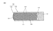
前記蓄熱材200の別の実施形態として、図2に示したように、前記蓄熱材200は、アラミド繊維210を所定形状の織物に形成するが、該アラミド織物210は、前記ケーシング100の内部断面形状に相応して円状に形成されて複数枚積層される。即ち、円状のアラミド織物210が前記ケーシング100を構成する片側閉鎖型円筒ケース110の挿入溝112内に複数枚積層され、該片側閉鎖型円筒ケース110にカバー120が結合されて前記挿入溝112を覆蓋する。
As another embodiment of the
前記蓄熱材200がアラミド綿である場合、該蓄熱材200の孔隙率は、アラミド綿をケーシング100の内部空間に挿入する量によって変わるが、前記蓄熱材200がアラミド織物である場合、該織物の目の大きさによって変わる。
When the
前記蓄熱材200の孔隙率は、パルス管冷凍機である場合、45%〜65%が効果的であり、スターリング冷凍機である場合、75%〜95%が効果的である。
When the
前記再生機は、作動ガスが圧縮される高温部と作動ガスが膨脹される冷凍部との間、即ち、前記高温部と冷凍部とを連結する流路に位置され、前記再生機の第1貫通孔113が高温部に位置し、第2貫通孔121が冷凍部に位置する。
The regenerator is positioned between a high temperature part where the working gas is compressed and a refrigeration part where the working gas is expanded, that is, in a flow path connecting the high temperature part and the freezing part. The
作動ガスが高温部から冷凍部に流動する場合、加熱された作動ガスが第1貫通孔113を通して挿入溝112に流入され、該挿入溝112に流入された作動ガスは、アラミド繊維からなる蓄熱材200を通過して第2貫通孔121を通して抜け出る。この過程で、前記高温部で加熱された作動ガスがアラミド繊維からなる蓄熱材200を通過しながら、その作動ガスの熱が蓄熱材200に吸収・蓄積され、作動ガスが相対的に低い温度状態で第2貫通孔121を通して抜け出る。前記第2貫通孔121を通して抜け出た作動ガスは、冷凍部に流入する。
When the working gas flows from the high temperature part to the refrigeration part, the heated working gas flows into the
また、作動ガスが冷凍部から高温部に流動する場合、冷却された作動ガスが第2貫通孔121を通して挿入溝112に流入し、該挿入溝112に流入した作動ガスは、アラミド繊維からなる蓄熱材200を通過して第1貫通孔113を通して抜け出る。この過程で、冷凍部で冷却された作動ガスがアラミド繊維からなる蓄熱材200を通過しながら、該蓄熱材200に蓄積された熱を受けて作動ガスが相対的に高い温度状態で第1貫通孔113を抜け出る。前記第1貫通孔113を通して抜け出た作動ガスは、高温部に流入する。
Further, when the working gas flows from the refrigeration part to the high temperature part, the cooled working gas flows into the
前記したように、高温部から冷凍部に往来する作動ガスがアラミド繊維からなる蓄熱材200を通過しながら、該蓄熱材200が作動ガスに含まれた熱を効果的に吸収して蓄積し、該蓄積された熱を効果的に作動ガスに伝達することで熱効率を高めることができる。また、前記蓄熱材200がアラミド繊維からなるので、非常に軽くなる。
As described above, while the working gas coming and going from the high temperature part passes through the
図3は、本発明に係る極低温冷凍機の一実施形態を示した断面図である。 FIG. 3 is a sectional view showing an embodiment of a cryogenic refrigerator according to the present invention.
図示したように、前記極低温冷凍機は、密閉容器300と、前記密閉容器300内に装着されて直線往復駆動力を発生する駆動モータ400と、前記密閉容器300内に装着されて内部に作動ガスが充填されたシリンダー500と、前記駆動モータ400の駆動力を受けて前記シリンダー500の内部で直線往復運動をしながら作動ガスをポンピングするピストン600と、前記密閉容器300に結合されて前記シリンダー500の内部と共に密閉された作動空間を形成するコールドフィンガーチューブ700と、前記密閉容器300に装着された弾性部材310に連結され、前記ピストン600の移動によって前記作動空間で往復運動をしながら作動ガスを圧縮/膨脹するディスプレーサ800と、前記作動ガスに含まれた熱を吸収して蓄積し、該蓄積された熱を作動ガスに放出するアラミド繊維からなる蓄熱材910を備えた再生機900と、を含んで構成されている。
As shown in the figure, the cryogenic refrigerator includes a sealed
前記駆動モータ400は、前記密閉容器300の内壁に固定される外側固定子410と、該外側固定子410と所定間隔を有して前記シリンダー500に固定結合される内側固定子420と、前記外側固定子410と内側固定子420との間に移動自在に挿入される可動子430と、を含んで構成される。前記外側固定子410には巻線コイル440が備えられており、前記可動子430には永久磁石450が備えられている。
The driving
前記シリンダー500は、前記密閉容器300の中間に位置するように結合されており、前記ピストン600は、前記シリンダー500の内部空間に挿入され、該ピストン600の一方の側が前記可動子430に連結される。
The
前記弾性部材310は、所定形状に形成された板スプリングであり、該板スプリングは、前記ピストン600と所定間隔を有して位置されている。
The
前記コールドフィンガーチューブ700は、一方の側が閉鎖された円筒状に形成される。また、前記コールドフィンガーチューブ700は、閉鎖部分が密閉容器300の外部に突出し、開放部分が前記シリンダー500の内部空間と連通するように前記密閉容器300の一方の側に固定結合される。
The
前記ディスプレーサ800は、所定長さ及び外径を有する第1スライディング軸部810と、前記第1スライディング軸部810から該第1スライディング軸部810よりも大きい外径及び所定長さを有して延長形成される第2スライディング軸部820と、該第2スライディング軸部820の端部に所定内径及び深さを有して形成される溝830と、前記第2スライディング軸部820の一方の側に前記溝830と連通して形成される第1貫通孔840と、を含んで構成される。前記ディスプレーサ800は、前記第1スライディング軸部810が前記ピストン600の内部に貫通形成された貫通穴610に挿入され、前記第2スライディング軸部820が作動空間に位置するように前記第1スライディング軸部810が前記弾性部材310に固定結合される。
The
前記再生機900は、所定長さを有して管状に形成され、前記ディスプレーサ800の第2スライディング軸部820に結合されて該第2スライディング軸部の溝830と共に挿入溝を形成する円筒ケース920と、該挿入溝に挿入されるアラミド繊維からなる蓄熱材910と、前記円筒ケース920を覆蓋するカバー930と、を含んで構成される。前記カバー930には、複数個の第2貫通孔931が形成されている。
The
前記蓄熱材910は、アラミド繊維が綿状に形成され、該アラミド綿は、前記挿入溝の内部に挿入される。また、前記アラミド繊維は、非金属材質であって高温でも変形しない。
In the
前記蓄熱材910のさらに別の実施形態として、図4に示したように、前記蓄熱材910は、アラミド繊維が所定形状の織物911に形成されて複数枚積層される。
As still another embodiment of the
前記所定形状の織物911は、前記挿入溝の内部断面形状に相応して円状に形成される。
The predetermined-shaped
前記蓄熱材910がアラミド綿である場合、該蓄熱材910の孔隙率は、アラミド綿を挿入溝、即ち再生機の内部空間に挿入する量によって変わり、前記蓄熱材910がアラミド織物である場合、該織物の目の大きさによって変わる。前記蓄熱材910の孔隙率は、パルス管冷凍機である場合、45%〜65%が効果的で、スターリング冷凍機である場合、75%〜95%が効果的である。
When the
前記再生機900は、前記ディスプレーサ800と結合され、前記コールドフィンガーチューブ700の内部空間及びシリンダー500の内部空間によって形成される作動空間内に移動自在に位置される。また、前記ディスプレーサ800の第2スライディング軸部820及び前記再生機900は、前記作動空間の内部を作動ガスの圧縮空間S1と作動ガスの膨脹空間S2とに区画する。
The
図中、未説明符号320は放熱手段で、510はガス通路である。
In the figure, the
以下、このような極低温冷凍機の作動を説明する。 Hereinafter, the operation of such a cryogenic refrigerator will be described.
まず、極低温冷凍機に電源が供給されると、駆動モータ400が作動しながら直線往復駆動力を発生する。次いで、前記駆動モータ400の駆動力がピストン600に伝達され、該ピストン600がシリンダー500の内部空間で直線往復運動をする。
First, when power is supplied to the cryogenic refrigerator, a linear reciprocating drive force is generated while the
次いで、前記ピストン600が前進運動をすると、ディスプレーサ800の第2スライディング軸部820の一方の側面とピストン600との間のシリンダー500の内部空間で作動ガスが圧縮加熱され、該圧縮加熱された作動ガスが、シリンダー500の端部に形成されたガス通路510及び第2スライディング軸部820の第1貫通孔840を通して再生機900の挿入溝に流入する。前記挿入溝に流入した作動ガスは、アラミド繊維からなる蓄熱材910を通過し、前記第2貫通孔931を通してコールドフィンガーチューブ700の一方の側の内部空間に流入する。前記圧縮加熱された作動ガスがアラミド繊維からなる蓄熱材910を通過しながら、該作動ガスの熱が蓄熱材910に吸収蓄積されて相対的に温度が低くなり、その相対的に温度が低くなった作動ガスが第2貫通孔931を通して抜け出る。
Next, when the
次いで、前記ピストン600の前進運動によって作動ガスが圧縮されながら、該圧縮された作動ガスの圧力がディスプレーサ800に作用し、該ディスプレーサが弾性部材310によって弾性的に支持されて前進運動をし、前記ディスプレーサ800の前進運動と共に再生機900も前進運動をする。前記ディスプレーサ800及び再生機900の前進運動は、ピストン600の前進運動と時間差をおいて進行する。
Next, while the working gas is compressed by the forward movement of the
次いで、前記ピストン600が後進運動をすると、シリンダーの内部空間の圧力差及び前記弾性部材310の復元力によってディスプレーサ800及び再生機900が後進運動をする。
Next, when the
次いで、前記ディスプレーサ800及び再生機900が後進運動をすることで、前記コールドフィンガーチューブ700の一方の側の内部空間に流入された作動ガスが急激に膨脹されながら外部の熱を吸収し、よって、該作動ガスが膨脹されるコールドフィンガーチューブ700の一部分が極低温で冷却される。ここで、前記コールドフィンガーチューブ700の冷却部分が冷凍部である。
Next, the
次いで、前記コールドフィンガーチューブ700の内部空間で膨脹されて相対的に温度が低くなった作動ガスは、前記第2貫通孔931を通して再生機900の挿入溝に流入し、該挿入溝に流入した作動ガスは、アラミド繊維からなる蓄熱材910を通過し、第1貫通孔840及びガス通路510を通して第2スライディング軸部820とピストン600との間のシリンダーの内部空間に流入する。温度の低い作動ガスが前記アラミド繊維からなる蓄熱材910を経ることで、該蓄熱材910に吸収蓄積された熱が前記作動ガスに伝達されながら、相対的に温度の高い作動ガスがシリンダー500の内部空間に流入する。
Next, the working gas, which is expanded in the internal space of the
このような過程が反復されることで、作動ガスが圧縮されるシリンダー500の内部空間は高温状態を維持し、作動ガスが膨脹されるコールドフィンガーチューブ700の一方の側、即ち、密閉容器300の外部に突出した部分は極低温状態を維持する。
By repeating such a process, the internal space of the
このように、前記極低温冷凍機は、駆動モータ400の駆動によってピストン600がシリンダー500の内部で作動ガスをポンピングするとともに、前記ピストン600の移動によってディスプレーサ800が移動しながら作動ガスを膨脹せしめ、コールドフィンガーチューブ700の一部分が短時間内に極低温状態になる。
Thus, in the cryogenic refrigerator, the driving
また、前記再生機900を構成する蓄熱材910が非金属材質であるアラミド繊維からなるので、前記再生機900が非常に軽くなる。従って、それら再生機900及びディスプレーサ800の組立体の重さが相対的に軽くなるため、前記組立体が横方向に位置する場合、該組立体が垂れることを防止し、コールドフィンガーチューブ700と再生機900との間の摩耗を最小化するだけでなく、ディスプレーサ800とピストン600とシリンダー500との間の摩耗を最小化することが可能となる。このように摩耗が減少されて前記再生機900が軽くなることで、前記ディスプレーサ800及び再生機900の振幅が相対的に増加し、作動ガスの膨脹効果及び各部品の信頼性が向上する。
Further, since the
また、前記高温部である圧縮空間と冷凍部である膨脹空間との間に位置し、それら圧縮空間及び膨脹空間を往復流動する作動ガスの熱を吸収して保存し、該保存された熱を再び作動ガスに放出する再生機900の蓄熱材910がアラミド繊維からなるので、該蓄熱材910が高温でも容易に変形せず、熱の蓄積/放出効率に優れて再生機900の性能が高くなることで、極低温冷凍機の性能が大幅に向上する。
Further, it is located between the compression space that is the high temperature part and the expansion space that is the freezing part, absorbs and stores the heat of the working gas that reciprocates in the compression space and the expansion space, and stores the stored heat. Since the
このとき、前記再生機を構成する蓄熱材として、アラミド繊維と一般的に使用されるステンレス繊維とを適用して質量及び伝熱面積を比較実験すると、アラミド繊維の場合、孔隙率が約80%の状態で、質量が約4.4g、伝熱面積が1.0592m2である反面、ステンレス繊維の場合、孔隙率が約90%の状態で、質量が約14.5g、伝熱面積が約0.5296m2である。 At this time, as a heat storage material constituting the regenerator, when an aramid fiber and a stainless steel fiber that is generally used are applied and the mass and heat transfer area are compared, in the case of an aramid fiber, the porosity is about 80%. In this state, the mass is about 4.4 g and the heat transfer area is 1.0592 m 2. On the other hand, in the case of stainless fiber, the porosity is about 90%, the mass is about 14.5 g, and the heat transfer area is about 0.5296 m 2 .
このように、アラミド繊維及びステンレス繊維の直径が同一であるとき、アラミド繊維の質量がステンレス繊維の質量よりも約1/4に減少し、伝熱面積は2.5倍増加して熱伝逹面積が上昇する。 Thus, when the diameter of the aramid fiber and the stainless steel fiber is the same, the mass of the aramid fiber is reduced to about 1/4 of the mass of the stainless steel fiber, the heat transfer area is increased by 2.5 times, and the heat transfer is increased. Increases area.
また、再生機の蓄熱材がステンレス繊維からなる極低温冷凍機と本発明の極低温冷凍機との冷却能力を比較実験すると、本発明の極低温冷凍機の場合、仕事率が28.46W、冷却能力が0.249である反面、再生機の蓄熱材がステンレス繊維からなる極低温冷凍機の場合、仕事率が15.86W、冷却能力が0.167である。このように、本発明の極低温冷凍機は、再生機の蓄熱材がステンレス繊維からなる極低温冷凍機よりも仕事率がほぼ2倍高くて冷却性能も高い。 Further, when comparing the cooling capacity of the cryogenic refrigerator of the present invention and the cryogenic refrigerator of the present invention where the heat storage material of the regenerator is a stainless steel fiber, the power of the cryogenic refrigerator of the present invention is 28.46 W, While the cooling capacity is 0.249, on the other hand, when the regenerator heat storage material is a cryogenic refrigerator made of stainless steel, the power is 15.86 W and the cooling capacity is 0.167. Thus, the cryogenic refrigerator of the present invention has a work rate almost twice as high as that of the cryogenic refrigerator in which the heat storage material of the regenerator is made of stainless fiber, and has a high cooling performance.
100 ケーシング
200 蓄熱材
300 密閉容器
400 駆動モータ
500 シリンダー
600 ピストン
700 コールドフィンガーチューブ
800 ディスプレーサ
810 第1スライディング軸部
820 第2スライディング軸部
830 溝
840 第1貫通孔
910 蓄熱材
920 円筒ケース
930 カバー
931 第2貫通孔
DESCRIPTION OF
Claims (6)
前記密閉容器内に装着されて直線往復駆動力を発生する駆動モータと、
前記密閉容器内に装着されて内部に作動ガスが充填されたシリンダーと、
前記駆動モータの駆動力を受けて前記シリンダーの内部で直線往復運動をしながら作動ガスをポンピングするピストンと、
前記密閉容器の一方の側に外部に突出するように結合され、前記シリンダーの内部と共に密閉された作動空間を形成するコールドフィンガーチューブと、
前記密閉容器に装着された弾性部材と連結され、前記ピストンの移動によって前記作動空間で往復運動をしながら作動ガスを圧縮/膨脹するディスプレーサと、
前記作動ガスが圧縮される高温部、及び作動ガスが膨脹される冷凍部を往来する作動ガスに含まれた熱を吸収して蓄積/放出する再生機と、を含み、
前記ディスプレーサは、
弾性部材に結合される第1スライディング軸部と、
前記第1スライディング軸部の端部から該第1スライディング軸部よりも大きい外径を有するように拡張されるとともに円筒状に延設されて前記作動空間に挿入される第2スライディング軸部と、
前記第2スライディング軸部の内部に所定内径及び深さを有して形成される溝と、
前記第2スライディング軸部の外周面から前記溝に貫通形成されて前記溝と高温部とを連通する第1貫通孔と、からなり、
前記再生機は、
前記第2スライディング軸部の外径と同一の外径を有して形成されて該第2スライディング軸部に結合される円筒ケースと、
該円筒ケースの内部及び前記溝により形成された挿入溝に挿入されてアラミド繊維からなる蓄熱材と、
前記第2円筒ケースの端部に結合されて挿入溝を覆蓋し、その内部に挿入溝と冷凍部とを連結する複数の第2貫通孔が形成されたカバーと、からなる、
ことを特徴とする極低温冷凍機。 A sealed container of a predetermined shape;
A drive motor mounted in the sealed container and generating a linear reciprocating drive force;
A cylinder mounted in the sealed container and filled with a working gas;
A piston that receives a driving force of the drive motor and pumps the working gas while reciprocating linearly inside the cylinder;
A cold finger tube which is coupled to one side of the sealed container so as to protrude outward and forms a sealed working space together with the inside of the cylinder;
A displacer connected to an elastic member mounted on the sealed container and compressing / expanding the working gas while reciprocating in the working space by the movement of the piston;
The hot portion working gas is compressed, and the playback machine working gas that absorb to storage / releasing heat contained in the working gas to traffic refrigeration unit to be inflated, only including,
The displacer is
A first sliding shaft coupled to the elastic member;
A second sliding shaft extending from the end of the first sliding shaft to have a larger outer diameter than the first sliding shaft and extending in a cylindrical shape and inserted into the working space;
A groove formed in the second sliding shaft portion with a predetermined inner diameter and depth;
A first through hole formed through the groove from the outer peripheral surface of the second sliding shaft portion and communicating the groove and the high temperature portion;
The player is
A cylindrical case formed to have the same outer diameter as that of the second sliding shaft portion and coupled to the second sliding shaft portion;
A heat storage material made of an aramid fiber inserted into an insertion groove formed by the groove and the inside of the cylindrical case;
A cover that is coupled to an end portion of the second cylindrical case to cover the insertion groove, and in which a plurality of second through holes that connect the insertion groove and the freezing portion are formed.
A cryogenic refrigerator characterized by that.
Applications Claiming Priority (1)
| Application Number | Priority Date | Filing Date | Title |
|---|---|---|---|
| KR1020030086559A KR100539756B1 (en) | 2003-12-01 | 2003-12-01 | Stirling refrigerator |
Publications (2)
| Publication Number | Publication Date |
|---|---|
| JP2005164225A JP2005164225A (en) | 2005-06-23 |
| JP4664045B2 true JP4664045B2 (en) | 2011-04-06 |
Family
ID=34464789
Family Applications (1)
| Application Number | Title | Priority Date | Filing Date |
|---|---|---|---|
| JP2004323632A Expired - Fee Related JP4664045B2 (en) | 2003-12-01 | 2004-11-08 | Regenerator and cryogenic refrigerator using the same |
Country Status (5)
| Country | Link |
|---|---|
| US (1) | US7275375B2 (en) |
| EP (1) | EP1538406A3 (en) |
| JP (1) | JP4664045B2 (en) |
| KR (1) | KR100539756B1 (en) |
| CN (1) | CN1287120C (en) |
Families Citing this family (17)
| Publication number | Priority date | Publication date | Assignee | Title |
|---|---|---|---|---|
| US8074457B2 (en) * | 2006-05-12 | 2011-12-13 | Flir Systems, Inc. | Folded cryocooler design |
| US7555908B2 (en) * | 2006-05-12 | 2009-07-07 | Flir Systems, Inc. | Cable drive mechanism for self tuning refrigeration gas expander |
| US8490414B2 (en) | 2007-05-16 | 2013-07-23 | Raytheon Company | Cryocooler with moving piston and moving cylinder |
| US8516834B2 (en) | 2008-08-14 | 2013-08-27 | S2 Corporation | Apparatus and methods for improving vibration isolation, thermal dampening, and optical access in cryogenic refrigerators |
| US10088203B2 (en) * | 2009-06-12 | 2018-10-02 | Raytheon Company | High efficiency compact linear cryocooler |
| KR20110097067A (en) * | 2010-02-24 | 2011-08-31 | 엘지전자 주식회사 | Radiator for cooler |
| KR20110097069A (en) * | 2010-02-24 | 2011-08-31 | 엘지전자 주식회사 | Piston valve's fixing structure for cooler |
| KR20110097070A (en) * | 2010-02-24 | 2011-08-31 | 엘지전자 주식회사 | Displacer valve for cooler |
| CN106152587B (en) * | 2015-03-30 | 2018-12-04 | 浙江大学 | A kind of vascular refrigerator |
| CN106052190B (en) * | 2016-06-01 | 2019-01-08 | 西安交通大学 | A kind of active back-heating type bullet refrigeration heat system |
| CN106288540B (en) * | 2016-08-30 | 2019-04-05 | 昆明物理研究所 | The processing method of filling body used in the regenerator and regenerator of sterlin refrigerator |
| US10422329B2 (en) | 2017-08-14 | 2019-09-24 | Raytheon Company | Push-pull compressor having ultra-high efficiency for cryocoolers or other systems |
| CN108931081B (en) * | 2018-06-22 | 2020-11-20 | 同济大学 | Preparation method of variable-porosity pill-shaped heat regenerator filler |
| CN109469989A (en) * | 2018-12-28 | 2019-03-15 | 浙江荣捷特科技有限公司 | Nonmetallic regenerator for -160 DEG C~0 DEG C warm area sterlin refrigerator |
| CN110081631A (en) * | 2019-04-12 | 2019-08-02 | 中国电子科技集团公司第十六研究所 | A kind of adhering method of sterlin refrigerator regenerator shell structure and its wearing layer |
| US11384964B2 (en) * | 2019-07-08 | 2022-07-12 | Cryo Tech Ltd. | Cryogenic stirling refrigerator with mechanically driven expander |
| JP7143272B2 (en) * | 2019-12-24 | 2022-09-28 | ツインバード工業株式会社 | Free piston Stirling refrigerator |
Citations (4)
| Publication number | Priority date | Publication date | Assignee | Title |
|---|---|---|---|---|
| JP2000009356A (en) * | 1998-06-19 | 2000-01-14 | Aisin Seiki Co Ltd | Cool-storage material, cool-storage apparatus, and cool- storage-type refrigerator to which those are applied |
| US6141971A (en) * | 1998-10-20 | 2000-11-07 | Superconductor Technologies, Inc. | Cryocooler motor with split return iron |
| JP2001021245A (en) * | 1999-07-09 | 2001-01-26 | Irie Koken Kk | Material and device for cold storage |
| JP2002295914A (en) * | 2001-03-30 | 2002-10-09 | Ekuteii Kk | Seat type cold storage member and its manufacturing method, and cold storage apparatus and freezer using same |
Family Cites Families (4)
| Publication number | Priority date | Publication date | Assignee | Title |
|---|---|---|---|---|
| DE10058101A1 (en) * | 2000-11-23 | 2002-06-06 | Rubitherm Gmbh | Latent heat storage body, method for producing a latent heat storage body, method for producing a film-like latent heat storage body and method for coating a carrier material |
| US6694730B2 (en) * | 2002-05-30 | 2004-02-24 | Superconductor Technologies, Inc. | Stirling cycle cryocooler with improved magnet ring assembly and gas bearings |
| US6688113B1 (en) * | 2003-02-11 | 2004-02-10 | Superconductor Technologies, Inc. | Synthetic felt regenerator material for stirling cycle cryocoolers |
| KR100644825B1 (en) * | 2004-01-29 | 2006-11-13 | 엘지전자 주식회사 | A cryocooler |
-
2003
- 2003-12-01 KR KR1020030086559A patent/KR100539756B1/en not_active IP Right Cessation
-
2004
- 2004-10-11 EP EP04292408A patent/EP1538406A3/en not_active Withdrawn
- 2004-10-18 US US10/965,918 patent/US7275375B2/en active Active
- 2004-11-08 JP JP2004323632A patent/JP4664045B2/en not_active Expired - Fee Related
- 2004-12-01 CN CNB2004100982887A patent/CN1287120C/en not_active Expired - Fee Related
Patent Citations (4)
| Publication number | Priority date | Publication date | Assignee | Title |
|---|---|---|---|---|
| JP2000009356A (en) * | 1998-06-19 | 2000-01-14 | Aisin Seiki Co Ltd | Cool-storage material, cool-storage apparatus, and cool- storage-type refrigerator to which those are applied |
| US6141971A (en) * | 1998-10-20 | 2000-11-07 | Superconductor Technologies, Inc. | Cryocooler motor with split return iron |
| JP2001021245A (en) * | 1999-07-09 | 2001-01-26 | Irie Koken Kk | Material and device for cold storage |
| JP2002295914A (en) * | 2001-03-30 | 2002-10-09 | Ekuteii Kk | Seat type cold storage member and its manufacturing method, and cold storage apparatus and freezer using same |
Also Published As
| Publication number | Publication date |
|---|---|
| US7275375B2 (en) | 2007-10-02 |
| CN1624403A (en) | 2005-06-08 |
| KR100539756B1 (en) | 2006-01-10 |
| EP1538406A2 (en) | 2005-06-08 |
| CN1287120C (en) | 2006-11-29 |
| JP2005164225A (en) | 2005-06-23 |
| EP1538406A3 (en) | 2009-01-21 |
| KR20050052961A (en) | 2005-06-07 |
| US20050223715A1 (en) | 2005-10-13 |
Similar Documents
| Publication | Publication Date | Title |
|---|---|---|
| JP4664045B2 (en) | Regenerator and cryogenic refrigerator using the same | |
| JP2552709B2 (en) | refrigerator | |
| JP2009236456A (en) | Pulse tube-type heat storage engine | |
| US20070234719A1 (en) | Energy conversion device and operation method thereof | |
| JP4718957B2 (en) | Pulse tube refrigerator | |
| JP2010071481A (en) | Thermal compressor and air conditioning device | |
| JP2007285630A (en) | Heat engine | |
| KR20110097069A (en) | Piston valve's fixing structure for cooler | |
| KR100284427B1 (en) | Driving motor cooling device of a pulse tube refrigerator | |
| CN219199535U (en) | Stirling refrigerator | |
| KR20110097067A (en) | Radiator for cooler | |
| KR20110097070A (en) | Displacer valve for cooler | |
| KR100311373B1 (en) | Oil-free pulse tube refrigerator | |
| KR100333397B1 (en) | Stirring Refrigerator | |
| KR100304567B1 (en) | Driving apparatus for oil-free pulse tube refrigerator | |
| KR100539755B1 (en) | Regenerator assembly structure for stirling refrigerator | |
| KR100304569B1 (en) | Structure for reducing gas-leakage of iol-free pulse tube refrigerator | |
| KR100367617B1 (en) | Pulstube refrigerator | |
| KR100374825B1 (en) | Cooling apparatus for pulstube cryogenic refrigerator | |
| KR100482012B1 (en) | Stirling cooler | |
| KR100273437B1 (en) | Linear actuator radiation structure | |
| KR20110097071A (en) | Valve for cooler | |
| KR100304566B1 (en) | Driving apparatus for oil-free pulse tube refrigerator | |
| KR20000009342A (en) | Non-lubricate pulse tube refrigerator | |
| KR20110097073A (en) | Cooler |
Legal Events
| Date | Code | Title | Description |
|---|---|---|---|
| A621 | Written request for application examination |
Free format text: JAPANESE INTERMEDIATE CODE: A621 Effective date: 20071025 |
|
| A131 | Notification of reasons for refusal |
Free format text: JAPANESE INTERMEDIATE CODE: A131 Effective date: 20100420 |
|
| A521 | Written amendment |
Free format text: JAPANESE INTERMEDIATE CODE: A523 Effective date: 20100716 |
|
| TRDD | Decision of grant or rejection written | ||
| A01 | Written decision to grant a patent or to grant a registration (utility model) |
Free format text: JAPANESE INTERMEDIATE CODE: A01 Effective date: 20101207 |
|
| A01 | Written decision to grant a patent or to grant a registration (utility model) |
Free format text: JAPANESE INTERMEDIATE CODE: A01 |
|
| A61 | First payment of annual fees (during grant procedure) |
Free format text: JAPANESE INTERMEDIATE CODE: A61 Effective date: 20110106 |
|
| R150 | Certificate of patent or registration of utility model |
Free format text: JAPANESE INTERMEDIATE CODE: R150 |
|
| FPAY | Renewal fee payment (event date is renewal date of database) |
Free format text: PAYMENT UNTIL: 20140114 Year of fee payment: 3 |
|
| R250 | Receipt of annual fees |
Free format text: JAPANESE INTERMEDIATE CODE: R250 |
|
| LAPS | Cancellation because of no payment of annual fees |