JP4663833B2 - Device for loading on top roller of draft device in drawing machine - Google Patents
Device for loading on top roller of draft device in drawing machine Download PDFInfo
- Publication number
- JP4663833B2 JP4663833B2 JP24696499A JP24696499A JP4663833B2 JP 4663833 B2 JP4663833 B2 JP 4663833B2 JP 24696499 A JP24696499 A JP 24696499A JP 24696499 A JP24696499 A JP 24696499A JP 4663833 B2 JP4663833 B2 JP 4663833B2
- Authority
- JP
- Japan
- Prior art keywords
- roller
- output
- pressure
- top roller
- side top
- Prior art date
- Legal status (The legal status is an assumption and is not a legal conclusion. Google has not performed a legal analysis and makes no representation as to the accuracy of the status listed.)
- Expired - Fee Related
Links
- 239000000835 fiber Substances 0.000 claims description 12
- 238000000034 method Methods 0.000 claims 8
- 238000004898 kneading Methods 0.000 claims 1
- 239000002657 fibrous material Substances 0.000 description 7
- 239000000463 material Substances 0.000 description 7
- 239000000853 adhesive Substances 0.000 description 6
- 230000001070 adhesive effect Effects 0.000 description 6
- 238000010586 diagram Methods 0.000 description 4
- 230000006835 compression Effects 0.000 description 3
- 238000007906 compression Methods 0.000 description 3
- 238000006116 polymerization reaction Methods 0.000 description 3
- 238000004804 winding Methods 0.000 description 3
- 230000005484 gravity Effects 0.000 description 2
- 239000000126 substance Substances 0.000 description 2
- 229920000742 Cotton Polymers 0.000 description 1
- 235000013871 bee wax Nutrition 0.000 description 1
- 239000012166 beeswax Substances 0.000 description 1
- 230000005540 biological transmission Effects 0.000 description 1
- 239000003795 chemical substances by application Substances 0.000 description 1
- 239000011248 coating agent Substances 0.000 description 1
- 238000000576 coating method Methods 0.000 description 1
- 230000008878 coupling Effects 0.000 description 1
- 238000010168 coupling process Methods 0.000 description 1
- 238000005859 coupling reaction Methods 0.000 description 1
- 230000000694 effects Effects 0.000 description 1
- 238000010438 heat treatment Methods 0.000 description 1
- 238000004519 manufacturing process Methods 0.000 description 1
- 239000002245 particle Substances 0.000 description 1
- 238000005498 polishing Methods 0.000 description 1
- 238000007761 roller coating Methods 0.000 description 1
- 239000004753 textile Substances 0.000 description 1
Images


Classifications
-
- D—TEXTILES; PAPER
- D01—NATURAL OR MAN-MADE THREADS OR FIBRES; SPINNING
- D01H—SPINNING OR TWISTING
- D01H5/00—Drafting machines or arrangements ; Threading of roving into drafting machine
- D01H5/18—Drafting machines or arrangements without fallers or like pinned bars
- D01H5/46—Loading arrangements
- D01H5/52—Loading arrangements using fluid pressure
- D01H5/525—Loading arrangements using fluid pressure for top roller arms
Description
【0001】
【発明の属する技術分野】
本発明は、ボトムローラとトップローラとを有する相前後して配置された複数のローラ対からなるドラフト装置のトップローラに負荷するスライバのための練条機に用いる装置であって、運転中はトップローラが加圧アーム内の負荷された加圧部材によってボトムローラに押し付けられ、停止中はトップローラが加圧アームによる負荷を受けないようにした装置に関する。
【0002】
【従来の技術】
運転中はドラフト装置において加圧アームが閉じられており、加圧部材がトップローラをドラフト装置の付属のボトムローラに押し付ける。練条機が特に比較的長時間にわたって運転停止状態にある場合は、加圧アームが開かれてトップローラの負荷が低減され、そうすることによってローラ(真円度)およびそれらの弾性的被覆が変形に対して保護されている。公知の装置では加圧アームが人手によって開放旋回させられる一方、トップローラはボトムローラ上で位置が固定したままである。このときトップローラは重力によって圧力を加える。トップローラとボトムローラとの間にはスライバが存在するので、停止中はトップローラがスライバ上に載ってこれを負荷している。運転中、特に1000m/min以上の高いスライバ進行速度ではローラは強く加熱される。繊維は加熱されると接着質になる様々な物質、たとえば綿では蜜蝋、化学繊維ではつや出し剤を含んでいる。ドラフト装置がたとえばスライバ破断、供給台における空ケンスと満ケンスの交換、故障などで比較的長時間、特に出口で満ケンスと空ケンスを交換する際より長時間停止していると、特にフロントローラがボトムフロントローラとのローラギャップで繊維に付着する物質を局所的に圧縮し、これらの物質が熱によって接着質になる結果を招く。この場合、それによってスライバが特にトップローラに固着し、運転再開時に回転するローラによって連行され、ローラが好ましくない巻き付きを生じることが不利である。その結果、ドラフト装置を直ちに遮断して、巻き付きを人手で取り除かなければならないので、著しい運転障害が引き起こされる。しかも多くの場合、障害は直ちに除去され得ないので、その結果として遅延、ひいては生産ロスを招く。
【0003】
【発明が解決しようとする課題】
本発明の課題は、上記の短所を回避して、ローラ巻き付きを簡単に回避し、または減少させる、冒頭に記載した種類の装置を提供することである。
【0004】
【課題を解決するための手段】
上記課題は、本発明により請求項1の特徴部に記載された特徴によって解決される。
【0005】
【発明の実施の形態】
トップローラのスライバに対する載置圧力がなくなり、特にトップローラが繊維材料と係合しないか、わずかしか係合しないことにより、スライバに踏まれた物質の加熱、したがって接着効果が回避される。このようにすることによって、スライバが好ましくない仕方でローラに固着するのが効果的に防止されるので、運転再開時の連行や巻き付きが起こらなくなる。
【0006】
単数または複数のトップフロントローラの負荷低減が自動的に行われることが合理的である。連続運転を継続する際に単数または複数のトップフロントローラの負荷が自動的に行われることが好都合である。4オーバ3方式ドラフト装置が存在しており、進行方向に見て出口に最も近いトップローラの負荷が低減可能であることが有利である。トップローラがガイドローラであることが好ましい。少なくとも1個のトップフロントローラがボトムフロントローラによって持ち上げられることが合理的である。単数および/または複数のトップフロントローラとスライバとの間に間隔が存在していることが好都合である。単数および/または複数のトップフロントローラに、空気圧シリンダのための独立に操作可能な空気圧弁が付属していることが好ましい。空気圧シリンダに、トップフロントローラのための少なくとも1つの調節可能な連行レバーなどが付属していることが好ましい。単数もしくは複数のトップフロントローラの負荷を低減するために、少なくとも1つの吊り上げ磁石などが設けられていることが合理的である。吊り上げ磁石が電気的に制御可能であることが好都合である。機械停止時に少なくとも1個のローラを自動的に繊維材料との接触から外すことができることが有利である。材料進行方向で最後のトップローラを自動的に繊維材料との接触から外すことができることが好ましい。機械の運転再開時に以前に持ち上げられたローラを再び自動的に加圧下で係合させることができることが合理的である。
【0007】
【実施例】
以下に、本発明の実施例を図面に基づいて詳細に説明する。
図1に示すように、たとえばツリュツラー社の練条機HSのドラフト装置は、4オーバ3方式ドラフト装置として設計されている。すなわち、ドラフト装置は3つのボトムローラI、II、III(ボトムフロントローラI、ボトムミドルローラII、ボトムバックローラIII)と、4つのトップローラ1、2、3、4からなる。ボトムフロントローラIには2つの負荷可能および負荷低減可能なトップフロントローラ1および2が付属しており、繊維進行方向Cで見て最後のトップフロントローラ1はガイドローラとして作用する。ドラフト装置内では、複数のスライバからなる重合スライバ5のドラフトが行われる。ドラフトはブレークドラフトとメインドラフトからなる。ローラ対4/IIIと3/IIはブレークドラフトゾーンを形成し、ローラ対3/IIと1、2/Iはメインドラフトゾーンを形成する。
【0008】
ボトムフロントローラIは、メインモータ(図示しない)によって駆動され、それによって供給速度を規定する。ボトムバックローラIIIおよびボトムミドルローラIIは変速モータ(図示しない)によって駆動される。トップローラ1〜4は、ジャーナル軸受10中心に矢印A、Bの方向で旋回可能な加圧アーム11a、11b、加圧部材6〜9(負荷装置)によりボトムローラI、II、IIIに押し付けられ、摩擦係合によってその駆動を得る。ローラI、II、III;1、2、3、4の回転方向は湾曲した矢印で示されている。複数のスライバからなる重合スライバ5はC方向に進行する。ボトムローラI、II、IIIは、機枠43に配置されたダイスに支承されている。2つの加圧アーム(旋回ヨーク)(図1には11aのみ示す)は、トップローラ(プレッシャーローラ)1、2、3もしくは4を受容するためのそれぞれ2つのプレッシャーローラ保持部の移動可能な受容の働きをする。
【0009】
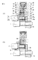
図2(A)および図2(B)に示すように、プレッシャーローラ保持部14は上側部分15と下側部分16とから組み立てられる。上側部分15はシリンダ中空室17を有するシリンダユニットを形成する。シリンダ中空室17内では、ピストン18が加圧棒19を介してスライドブシュ20内で案内されている。加圧棒19はスライドブシュ21内でも案内されており、スライドブシュ21自体は下側部分16内に配置されている。プレッシャーローラ1のローラ頸部1aは押さえ板24a内の開口部を貫通して軸受22内に嵌入している。プレッシャーローラ4を受容する軸受22はプレッシャーローラ保持具14とボトムローラIのローラ頸部との間の空間23内で延びている。
【0010】
ダイヤフラム25がシリンダ中空室17を圧力に関して区分している。シリンダ中空室17の上側部分内で圧力を形成するために、同部分に圧縮空気接続部から圧縮空気を供給できる。シリンダ中空室17の下側部分は排気孔によって排気される。相応にシリンダ中空室17の上側部分を排気し、シリンダ中空室17の下側部分に圧縮空気を供給することもできる。
【0011】
運転中、重合スライバ5がボトムローラI、II、IIIを通って案内された後で、加圧アーム11a(およびまた図示されていない加圧アーム11b)は図1に示されている作業位置に旋回させられ、この位置に固定されるので、プレッシャーローラ1、2、3、4は重合スライバ5をボトムローラI、II、IIIに圧縮することができる。この圧縮は、一方では加圧棒19a〜19dがそれぞれ相応の軸受22a〜22d上に載っており、他方ではダイヤフラム25の上方の中空室が過圧状態にもたらされたことによって生じる。それにより加圧棒19はその他方の端部で軸受22を押圧し、トップローラ1とボトムローラ(駆動ローラ)Iとの間の上記の圧縮を形成する。加圧棒19は矢印D、Eの方向で移動可能である。
【0012】
加圧棒19には連行部材として、矢印F、Gの方向で摺動可能なスライドピン26が90°の角度で付属している。このスライドピン26は長穴27を有しており、この長穴27を通って加圧棒19に固定されているねじ28などが貫通している。スライドピン26はその一方の端部で軸受ケーシング29内に支承されており、この軸受ケーシング29内にスライドピン26の往復運動のための駆動装置(図示しない)が存在している。軸受ケーシング29は矢印H、Iの方向で摺動可能である。押さえ板24aはスライドピン26の高さに貫通孔30を有している。スライドピンは矢印Gの方向で摺動することによって、貫通孔30内で、もしくは貫通孔30を通って形状接続により係合する。
【0013】
図3(A)に示すように、加圧アーム12aは内方旋回しており、空気圧式加圧部材9の加圧棒19は軸受22を押す。スライドピン26は押さえ板24aと係合していない。加圧アーム12aは矢印K、Lの方向でジャーナル軸受32の回りを回転可能である。ジャーナル軸受32は機枠35にダイス13を介して固定されている。図3(B)に示すように、スライドピン26は矢印Gの方向に摺動し、押さえ板24の貫通孔30を貫通する。次いで加圧棒19は矢印Eの方向に摺動する。スライドピン26はねじ28を介して加圧棒19に接続されているので(図2(A)、2(B)参照)、押さえ板24aはトップローラ1と一緒にやはりE方向で加圧棒19と同じ量だけ持ち上げられる。このとき軸受22の継ぎ足し部22′はダイス13の支持部13aから持ち上げられる。同時にすべり軸受33を介して加圧アーム11aに摺動可能に支承されているケーシング29も、矢印Nの方向で加圧棒19と同じ量だけ摺動する。トップローラ1の負荷は低減されている。次いで、スライドピン26が押さえ板24と形状接続によって係合しているので、トップローラ1は同様にN方向で摺動し、それによってボトムローラから持ち上げられる。
【0014】
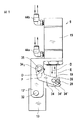
図4(A)に示すように、運転中はトップフロントローラ1および2は、ボトムフロントローラI上に載っており、トップフロントローラ1および2とボトムフロントローラIIとの間を繊維材料5が通過する。駆動モータ用の電子制御調節装置(図示しない)で比較的長い障害が確認されると、トップフロントローラ1は負荷が低減され、それに続いて直ちに繊維材料5もしくはボトムフロントローラIから量aだけ持ち上げられる。そうすることによって、繊維材料5が異物などを介しての圧縮によりトップフロントローラ1に固着するのが防がれる。このときトップフロントローラ2は負荷が低減され、それにより重力の作用を受けているので、繊維材料5はトップフロントローラ2とボトムフロントローラIとの間に把持され、運転再開時にトップフロントローラ1とボトムフロントローラIとによって問題なく案内されることができる。
【0015】
図5に示すように、レバー34として形成された連行部材は、その一方の端部34′で、加圧アーム12の側部支持体12′に固定されたジャーナル軸受35を介して矢印O、Pの方向に回転可能に枢着されている。レバー34はシングルアーム式の鈍角アングルレバーとして形成されている。レバー34の他方の端部は、片側が長穴状に開いた切欠部34′を有してフォーク状に形成されており、この切欠部34′を通って中間部材36に固定されたピン28などが貫通する。中間部材36自体は加圧棒19に取り付けられている。レバー34のフォーク状端部は、押さえ板24aの開口部30に嵌入できる連行突起34″を有している。加圧棒19が矢印Eの方向に摺動すると、同時に中間部材36とピン28との強制カップリングにより連行突起34″はE方向に、軸受35を中心とする円軌道を描いて摺動する。このときレバー34は矢印Pの方向に回転し、開口部34′はピン28の方向に動くので、連行突起34″は自由に外方に向かってピン28による境界の外部に達する。このようにして、連行突起34″は開口部30と係合できるようにされる。これに対して加圧棒19が矢印Dの方向に移動すると、すべての運動は反対方向に行われる。
【0016】
ドラフト装置の負荷装置の空気圧制御は2つの5/2方向切替弁(図6(A)、図6(B)参照)で行われる。トップフロントローラ1の負荷のために、独立に制御可能な固有の5/2方向切替弁が存在している。この場合、次の3つの切替状態が可能である。
A.ピストン18を下方死点において圧縮空気で負荷する。すなわちトップローラ1〜4は負荷されている。このとき各々のトップローラ1〜4の負荷力は圧力調節器42によって個別に調節できる。さらに、安全のために圧力スイッチで圧力を監視する。
B.ピストン18を下方死点において無圧状態(排気)に切り替える。すなわち、トップローラ1〜4は固定されていないので、ドラフト装置の負荷が低減される。この状態は機械停止時に自動的に形成される(図5)。それによってトップローラ被覆および材料が保護される。
C.ピストン18を上方死点で圧縮空気で負荷する。すなわちトップローラ1は持ち上げられる(図4(B))。
【0017】
図6(A)に示すように、空気圧式弁調節装置38では5/2方向切替弁39には電磁コイル40が付属している。5/2方向切替弁39は気流のために給気ポート39a、第1の排気ポート39b、第2の排気ポート39c、作動ポート39d(方向1)および作動ポート39e(方向2)を有している。図6(B)には5/2方向切替弁39の線図が示されている。作動ポート39dにより3つの切替状態が実現できる。別の作動ポート39eは閉鎖し、またはたとえばスライドピン26(図2および図3)の空気圧制御のために用いることができる。矢印は気流の方向を示している。
【0018】
本発明は空気圧式加圧部材(負荷部材)の例で説明した。トップローラ1〜4の負荷のための機械的、油圧的または電気的加圧部材を用いることもできる。
【0019】
実用的にガイドローラ1には多くの巻き付きが生じるが、これらは繊維中に存在しているつや出し剤や接着粒子が原因で起こる。機械の障害(スライバ破断、ケンス交換など)の後で、操作員が障害を直ちに除去することはしばしば不可能である。障害後に練条機はドラフト装置の負荷を低減するが、高温のガイドローラ1は自重で繊維5の上に載っている。高温のガイドローラ1が接着性の繊維5上に比較的長時間載っていると、これらの繊維5がガイドローラ1に接着し、機械のスタート時に接着性の繊維5がガイドローラ1に巻き付く。本発明の装置により、障害後に独立の弁でガイドローラ1を持ち上げることが可能である。ガイドローラ1を持ち上げることにより、繊維5は接着しなくなり、ボトムローラIにかかる圧力が低減される。そうすることによって巻き付き傾向は著しく減少する。この巻き付き傾向の減少は、接着性の繊維が存在する場合に練条機の利用効率を著しく高める。なぜならば、運転障害およびその除去が減少するか、あるいは防止されているからである。
【図面の簡単な説明】
【図1】本発明の装置を有するドラフト装置の側面図である。
【図2】本発明の装置である、空気圧によって負荷されるプレッシャーローラ保持部を示す側断面図であって、図2(A)はトップローラが加圧されている状態での図1の線I−Iによる側断面図であり、図2(B)は、トップローラが加圧されていない状態での図2(A)と同様の側断面図である。
【図3】本発明の装置を有するトップローラの各態様を示す部分図であって、図3(A)は加圧アームが内方旋回して連行部材が係合から外れている状態を示す部分図であり、図3(B)は加圧アームが内方旋回して連行部材が係合している状態を示す部分図であり、図3(C)は、加圧アームがトップローラと一緒に持ち上げられている状態を示す部分図である。
【図4】本発明の装置におけるトップローラとボトムローラの関係を示す側面図であって、図4(A)は各トップローラが負荷されて運転中のドラフト装置を示す側面図であり、図4(B)はトップローラの負荷が軽減されてトップフロントローラ(ガイドローラ)が持ち上げられている運転停止中のドラフト装置を示す図である。
【図5】本発明の装置における連行部材の配置を示す側面図である。
【図6】空気圧式5/2方向切替弁を示す図であって、図6(A)は略示側面図、図6(B)はその作動線図である。
【符号の説明】
1…トップフロントローラ
2、3、4…トップローラ
I、II、III…ボトムローラ
5…繊維材料(重合スライバ)
6〜9…加圧部材
11a、11b…加圧アーム
14…プレッシャーローラ保持部
18…ピストン
19…加圧棒
22a〜22d…軸受
35…機枠[0001]
BACKGROUND OF THE INVENTION
The present invention is an apparatus for use in a drawing machine for a sliver that loads a top roller of a draft device composed of a plurality of roller pairs arranged one after the other having a bottom roller and a top roller. The present invention relates to an apparatus in which a top roller is pressed against a bottom roller by a loaded pressure member in a pressure arm so that the top roller is not subjected to a load by the pressure arm during a stop.
[0002]
[Prior art]
During operation, the pressure arm is closed in the draft device, and the pressure member presses the top roller against the bottom roller attached to the draft device. The press arm is opened to reduce the load on the top roller, especially when the drawing machine has been out of service for a relatively long time, so that the rollers (roundness) and their elastic coating Protected against deformation. In known devices, the pressure arm is pivoted open by hand, while the top roller remains fixed on the bottom roller. At this time, the top roller applies pressure by gravity. Since a sliver exists between the top roller and the bottom roller, the top roller rests on the sliver and loads it during the stop. During operation, the roller is strongly heated, particularly at a high sliver speed of 1000 m / min or higher. Fibers contain various substances that become adhesive when heated, such as beeswax for cotton and polishes for chemical fibers. If the draft device is stopped for a relatively long time, for example, due to sliver breakage, exchange of empty and full cans at the supply stand, failure, etc. Will locally compress the material that adheres to the fiber in the roller gap with the bottom front roller, and these materials will become adhesive due to heat. In this case, it is disadvantageous that the sliver thereby adheres in particular to the top roller and is entrained by the rotating roller when operation is resumed, causing the roller to be undesirably wound. As a result, the drafting device must be immediately shut off and the wrapping must be manually removed, causing significant operational disturbances. Moreover, in many cases, the fault cannot be removed immediately, resulting in a delay and thus a production loss.
[0003]
[Problems to be solved by the invention]
The object of the present invention is to provide an apparatus of the kind described at the outset, which avoids the above disadvantages and simply avoids or reduces roller wrapping.
[0004]
[Means for Solving the Problems]
The above object is solved by the features described in the characterizing portion of
[0005]
DETAILED DESCRIPTION OF THE INVENTION
There is no mounting pressure on the sliver of the top roller, and in particular, the top roller does not engage the fiber material or only slightly, thereby avoiding the heating of the material stepped on the sliver and thus the bonding effect. This effectively prevents the sliver from adhering to the roller in an unfavorable manner, so that entrainment and winding at the time of resuming operation do not occur.
[0006]
It is reasonable to automatically reduce the load on the top front roller or rollers. Conveniently, the load on the top front roller or rollers is automatically applied when continuing the continuous operation. Advantageously, a 4 over 3 draft device is present and the load on the top roller closest to the exit as seen in the direction of travel can be reduced. The top roller is preferably a guide roller. It is reasonable that at least one top front roller is lifted by the bottom front roller. Conveniently, there is a gap between the top and front roller and the sliver. The top and front rollers are preferably associated with independently operable pneumatic valves for the pneumatic cylinder. The pneumatic cylinder is preferably accompanied by at least one adjustable entrainment lever or the like for the top front roller. In order to reduce the load on one or more top front rollers, it is reasonable that at least one lifting magnet or the like is provided. Conveniently, the lifting magnet is electrically controllable. Advantageously, at least one roller can be automatically removed from contact with the fiber material when the machine is stopped. Preferably, the last top roller in the direction of material travel can be automatically removed from contact with the fiber material. It is reasonable that the previously lifted roller can be automatically re-engaged under pressure when the machine resumes operation.
[0007]
【Example】
Embodiments of the present invention will be described below in detail with reference to the drawings.
As shown in FIG. 1, for example, the drafting device HS of the Trutzler company is designed as a 4 over 3 drafting device. That is, the draft device includes three bottom rollers I, II, and III (bottom front roller I, bottom middle roller II, and bottom back roller III) and four
[0008]
The bottom front roller I is driven by a main motor (not shown), thereby defining a supply speed. The bottom back roller III and the bottom middle roller II are driven by a transmission motor (not shown). The
[0009]
As shown in FIGS. 2A and 2B, the pressure
[0010]
A
[0011]
During operation, after the
[0012]
A
[0013]
As shown in FIG. 3A, the
[0014]
As shown in FIG. 4A, during operation, the top
[0015]
As shown in FIG. 5, the entraining member formed as a
[0016]
Air pressure control of the load device of the draft device is performed by two 5 / 2-way switching valves (see FIGS. 6A and 6B). Due to the load on the top
A. The
B. The
C. The
[0017]
As shown in FIG. 6A, in the pneumatic
[0018]
The present invention has been described with an example of a pneumatic pressure member (load member). Mechanical, hydraulic or electrical pressure members for loading the top rollers 1-4 can also be used.
[0019]
Practically, the
[Brief description of the drawings]
FIG. 1 is a side view of a draft device having a device of the present invention.
2 is a side sectional view showing a pressure roller holding portion loaded by air pressure, which is an apparatus of the present invention, and FIG. 2 (A) is a line of FIG. 1 in a state where a top roller is pressurized. FIG. 2B is a side sectional view taken along line II, and FIG. 2B is a side sectional view similar to FIG. 2A in a state where the top roller is not pressurized.
FIG. 3 is a partial view showing each aspect of the top roller having the apparatus of the present invention, and FIG. 3 (A) shows a state in which the pressure arm is pivoted inward and the entraining member is disengaged. FIG. 3B is a partial view showing a state where the pressure arm is pivoted inward and the entraining member is engaged, and FIG. 3C is a view showing that the pressure arm is a top roller. It is a fragmentary figure which shows the state currently lifted together.
4 is a side view showing the relationship between the top roller and the bottom roller in the apparatus of the present invention, and FIG. 4 (A) is a side view showing the draft device in operation with each top roller being loaded. 4 (B) is a diagram showing a draft device during operation stop where the load on the top roller is reduced and the top front roller (guide roller) is lifted.
FIG. 5 is a side view showing the arrangement of entraining members in the apparatus of the present invention.
6A and 6B are diagrams showing a pneumatic 5 / 2-direction switching valve, in which FIG. 6A is a schematic side view and FIG. 6B is an operation diagram thereof.
[Explanation of symbols]
DESCRIPTION OF
6-9 ...
Claims (6)
さらに、 further,
前記トップローラを担持する加圧アームと、 A pressure arm carrying the top roller;
前記加圧アームに含まれていて、前記トップローラのそれぞれを前記ボトムローラのそれぞれに押付ける加圧部材と、を具備する練篠機の動作方法において、 In the operation method of the machine, the pressure arm is included in the pressure arm, and the pressure member presses each of the top rollers against each of the bottom rollers.
前記練篠機の運転時に、前記スライバを前記ローラ対の間隙に連続的に通過させつつ、前記加圧部材が前記トップローラを前記ボトムローラのそれぞれに押付ける工程(a)と、 A step (a) in which the pressure member presses the top roller against each of the bottom rollers while continuously passing the sliver through the gap between the roller pairs during operation of the kneading machine;
前記運転の中断時に、前記出力側トップローラと前記出力側ボトムローラとの間の間隙に位置する前記スライバに対して、前記出力側トップローラがわずかな圧力を及ぼす程度に、前記出力側トップローラの押圧力のみを解放する工程(b)とを含む、動作方法。 When the operation is interrupted, the output-side top roller is applied to such a degree that the output-side top roller exerts a slight pressure on the sliver located in the gap between the output-side top roller and the output-side bottom roller. And (b) releasing only the pressing force.
さらに、前記工程(b)は、前記第一および前記第二の出力側トップローラの押圧力のみを解放するようにした請求項1に記載の動作方法。 Furthermore, the said process (b) is the operation | movement method of Claim 1 which released only the pressing force of said 1st and said 2nd output side top roller.
Applications Claiming Priority (2)
| Application Number | Priority Date | Filing Date | Title |
|---|---|---|---|
| DE19839885A DE19839885B4 (en) | 1998-09-02 | 1998-09-02 | Device on a stretch for textile fiber ribbons with load on the top rollers of the drafting system |
| DE19839885:9 | 1998-09-02 |
Publications (3)
| Publication Number | Publication Date |
|---|---|
| JP2000096357A JP2000096357A (en) | 2000-04-04 |
| JP2000096357A5 JP2000096357A5 (en) | 2006-08-10 |
| JP4663833B2 true JP4663833B2 (en) | 2011-04-06 |
Family
ID=7879489
Family Applications (1)
| Application Number | Title | Priority Date | Filing Date |
|---|---|---|---|
| JP24696499A Expired - Fee Related JP4663833B2 (en) | 1998-09-02 | 1999-09-01 | Device for loading on top roller of draft device in drawing machine |
Country Status (6)
| Country | Link |
|---|---|
| US (1) | US6154931A (en) |
| JP (1) | JP4663833B2 (en) |
| CH (1) | CH694735A5 (en) |
| DE (1) | DE19839885B4 (en) |
| GB (1) | GB2344112B (en) |
| IT (1) | IT1313126B1 (en) |
Families Citing this family (12)
| Publication number | Priority date | Publication date | Assignee | Title |
|---|---|---|---|---|
| KR20000051783A (en) * | 1999-01-26 | 2000-08-16 | 윤종용 | Nonvolatile memory device |
| US6393942B1 (en) * | 2000-09-29 | 2002-05-28 | Brown Machine, Llc | Method of driving ejector pins to eject formed parts |
| CH696467A5 (en) * | 2002-07-29 | 2007-06-29 | Truetzschler Gmbh & Co Kg | Apparatus for loading of the top rollers of a drafting for textile slivers. |
| DE10255640B3 (en) * | 2002-11-28 | 2004-01-22 | Rexroth Mecman Gmbh | Pressure cylinder, in particular for a drafting system of a textile machine |
| DE10314428B4 (en) * | 2003-03-31 | 2007-03-29 | Bosch Rexroth Pneumatics Gmbh | Double-pressure cylinder arrangement and loading device of a textile machine with such a double-pressure cylinder arrangement |
| DE10317430B4 (en) * | 2003-04-15 | 2011-05-12 | Rieter Ingolstadt Gmbh | Textile machine with a drafting system |
| DE10331759B4 (en) * | 2003-07-14 | 2012-03-29 | Trützschler GmbH & Co Kommanditgesellschaft | Device on a stretch for textile fiber ribbons with loading and unloading of drafting crown rollers |
| DE102005020506A1 (en) * | 2005-04-29 | 2006-11-09 | TRüTZSCHLER GMBH & CO. KG | Device on a drafting system of a spinning machine, in particular track, card, combing machine o. The like., To load the drafting rollers, with at least one pressure cylinder |
| CN100389234C (en) * | 2005-06-26 | 2008-05-21 | 常德纺织机械有限公司 | Novel spinning, drawing and pressuring device |
| DE102006048742B4 (en) * | 2006-10-11 | 2021-06-10 | Trützschler GmbH & Co Kommanditgesellschaft | Device on a drafting system of a spinning machine for loading the drafting system rollers, with at least one pressure cylinder |
| CN104109916A (en) * | 2014-07-16 | 2014-10-22 | 张家港市华阳针纺织品有限公司 | Drafting device of roller drafting drawing frame |
| CH712605A1 (en) * | 2016-06-24 | 2017-12-29 | Rieter Ag Maschf | Drafting system for drawing a strand-like fiber composite as well as textile machine equipped therewith. |
Family Cites Families (13)
| Publication number | Priority date | Publication date | Assignee | Title |
|---|---|---|---|---|
| US2890495A (en) * | 1957-07-25 | 1959-06-16 | Alsacienne Constr Meca | Textile drafting apparatus |
| FR1201069A (en) * | 1957-08-26 | 1958-12-28 | ||
| DE1171314B (en) * | 1962-01-19 | 1964-05-27 | Skf Kugellagerfabriken Gmbh | Top roller support and loading arm for spinning machine drafting systems |
| US3310847A (en) * | 1964-06-09 | 1967-03-28 | Maremont Corp | Helical draft rolls |
| JPS5915520A (en) * | 1982-07-15 | 1984-01-26 | Toyoda Autom Loom Works Ltd | Roll pressurizing apparatus in drafting mechanism |
| DE3406397C1 (en) * | 1984-02-22 | 1985-07-11 | SKF GmbH, 8720 Schweinfurt | Match lock device on spinning machine drafting systems |
| NL8700932A (en) * | 1987-05-19 | 1988-11-16 | Kostromskoe Sp K Bjuro Textiln | MACHINE FOR THE MANUFACTURE OF TWISTLESS YARN FROM FLAT FIBER. |
| IT1244444B (en) * | 1990-09-13 | 1994-07-15 | Linimpianti Srl | PRESSER DEVICE FOR A YARN IRONING MACHINE |
| US5477591A (en) * | 1994-03-17 | 1995-12-26 | Hollingsworth Saco Lowell, Inc. | Bearing device for drafting rollers having pressure relieving means |
| IT237101Y1 (en) * | 1994-08-13 | 2000-08-31 | Truetzschler & Co | DEVICE FOR SURVEILLANCE OF A WINDING FORMATION ON AT LEAST A COUPLE OF CYLINDERS DRIVING A CARDA TAPE |
| DE19548840B4 (en) * | 1995-12-27 | 2008-04-03 | Rieter Ingolstadt Spinnereimaschinenbau Ag | Track for doubling and stretching slivers |
| US5761772A (en) * | 1996-07-19 | 1998-06-09 | North Carolina State University | Securing and pressuring system for drafting rollers for automated textile drafting system |
| DE19704815A1 (en) * | 1997-02-08 | 1998-08-13 | Truetzschler Gmbh & Co Kg | Load application mechanism for rolls on a textile fibre band stretching unit |
-
1998
- 1998-09-02 DE DE19839885A patent/DE19839885B4/en not_active Revoked
-
1999
- 1999-08-13 US US09/373,563 patent/US6154931A/en not_active Expired - Fee Related
- 1999-08-30 IT IT1999MI001847A patent/IT1313126B1/en active
- 1999-09-01 GB GB9920657A patent/GB2344112B/en not_active Expired - Fee Related
- 1999-09-01 JP JP24696499A patent/JP4663833B2/en not_active Expired - Fee Related
- 1999-09-01 CH CH01591/99A patent/CH694735A5/en not_active IP Right Cessation
Also Published As
| Publication number | Publication date |
|---|---|
| JP2000096357A (en) | 2000-04-04 |
| GB2344112A (en) | 2000-05-31 |
| CH694735A5 (en) | 2005-06-30 |
| IT1313126B1 (en) | 2002-06-17 |
| DE19839885B4 (en) | 2010-04-01 |
| US6154931A (en) | 2000-12-05 |
| ITMI991847A0 (en) | 1999-08-30 |
| DE19839885A1 (en) | 2000-03-09 |
| GB9920657D0 (en) | 1999-11-03 |
| GB2344112B (en) | 2002-12-11 |
| ITMI991847A1 (en) | 2001-03-02 |
Similar Documents
| Publication | Publication Date | Title |
|---|---|---|
| JP4663833B2 (en) | Device for loading on top roller of draft device in drawing machine | |
| JPS6327450B2 (en) | ||
| US5799374A (en) | Spinning machine for the doubling or stretching of fiber bands | |
| JPS5915520A (en) | Roll pressurizing apparatus in drafting mechanism | |
| EP2463416A2 (en) | Drafting device in fore-spinning process | |
| US7251863B2 (en) | Draw frame for textile fibre slivers having a drawing system with top rollers that can be loaded and relieved of load | |
| JPH10226927A (en) | Device for sliver draw frame loading on top roller in drafting unit | |
| JP2000096357A5 (en) | ||
| CN106044322A (en) | Rolling device for spinning | |
| JP2006316369A (en) | Roller contact-changing over apparatus of cradle in draft apparatus | |
| JP2002087699A (en) | Winding device for textile machinery manufacturing cross winding bobbin | |
| CN105297148A (en) | Jute processing system | |
| CN105316771A (en) | A simple jute processing system | |
| CN218454242U (en) | Exempt from to hang gauze structure | |
| CN205062237U (en) | Simple and easy jute carding unit | |
| JP6120602B2 (en) | Draft device for drafting roving yarn | |
| JPS6036610Y2 (en) | Loading device of drawing machine | |
| CN110528126B (en) | Drafting device for spinning machine and drafting device unit | |
| US3831364A (en) | Spinning machines having spindle rails movable for tube exchanging | |
| CN115354419A (en) | Exempt from to hang gauze structure | |
| JPH03124821A (en) | Spinning machine furnished with double belts drawing frame | |
| JPH08157145A (en) | Filament yarn waxing device | |
| JPH0826537A (en) | Lap winding method | |
| JPH0535858U (en) | Pressing device for apron in draft device | |
| JPS5921968B2 (en) | How to start and stop an open-end spinning machine and its device |
Legal Events
| Date | Code | Title | Description |
|---|---|---|---|
| A521 | Request for written amendment filed |
Free format text: JAPANESE INTERMEDIATE CODE: A523 Effective date: 20060626 |
|
| A621 | Written request for application examination |
Free format text: JAPANESE INTERMEDIATE CODE: A621 Effective date: 20060626 |
|
| A977 | Report on retrieval |
Free format text: JAPANESE INTERMEDIATE CODE: A971007 Effective date: 20080827 |
|
| A131 | Notification of reasons for refusal |
Free format text: JAPANESE INTERMEDIATE CODE: A131 Effective date: 20080909 |
|
| A521 | Request for written amendment filed |
Free format text: JAPANESE INTERMEDIATE CODE: A523 Effective date: 20081016 |
|
| A131 | Notification of reasons for refusal |
Free format text: JAPANESE INTERMEDIATE CODE: A131 Effective date: 20090407 |
|
| A521 | Request for written amendment filed |
Free format text: JAPANESE INTERMEDIATE CODE: A523 Effective date: 20090519 |
|
| A02 | Decision of refusal |
Free format text: JAPANESE INTERMEDIATE CODE: A02 Effective date: 20090915 |
|
| A01 | Written decision to grant a patent or to grant a registration (utility model) |
Free format text: JAPANESE INTERMEDIATE CODE: A01 |
|
| A61 | First payment of annual fees (during grant procedure) |
Free format text: JAPANESE INTERMEDIATE CODE: A61 Effective date: 20110106 |
|
| R150 | Certificate of patent or registration of utility model |
Ref document number: 4663833 Country of ref document: JP Free format text: JAPANESE INTERMEDIATE CODE: R150 Free format text: JAPANESE INTERMEDIATE CODE: R150 |
|
| FPAY | Renewal fee payment (event date is renewal date of database) |
Free format text: PAYMENT UNTIL: 20140114 Year of fee payment: 3 |
|
| R250 | Receipt of annual fees |
Free format text: JAPANESE INTERMEDIATE CODE: R250 |
|
| R250 | Receipt of annual fees |
Free format text: JAPANESE INTERMEDIATE CODE: R250 |
|
| R250 | Receipt of annual fees |
Free format text: JAPANESE INTERMEDIATE CODE: R250 |
|
| R250 | Receipt of annual fees |
Free format text: JAPANESE INTERMEDIATE CODE: R250 |
|
| R250 | Receipt of annual fees |
Free format text: JAPANESE INTERMEDIATE CODE: R250 |
|
| LAPS | Cancellation because of no payment of annual fees |