JP4663138B2 - Manufacturing method of color filter - Google Patents
Manufacturing method of color filter Download PDFInfo
- Publication number
- JP4663138B2 JP4663138B2 JP2001039434A JP2001039434A JP4663138B2 JP 4663138 B2 JP4663138 B2 JP 4663138B2 JP 2001039434 A JP2001039434 A JP 2001039434A JP 2001039434 A JP2001039434 A JP 2001039434A JP 4663138 B2 JP4663138 B2 JP 4663138B2
- Authority
- JP
- Japan
- Prior art keywords
- ink
- color filter
- transparent substrate
- area
- colored
- Prior art date
- Legal status (The legal status is an assumption and is not a legal conclusion. Google has not performed a legal analysis and makes no representation as to the accuracy of the status listed.)
- Expired - Fee Related
Links
Images


Description
【0001】
【発明の属する技術分野】
本発明は、カラーテレビ、パーソナルコンピュータ、パチンコ遊技台等に使用されるカラー表示の液晶素子と、該液晶素子の構成部材であるカラーフィルタとその製造方法に関する。
【0002】
【従来の技術】
近年、パーソナルコンピュータの発達、特に携帯用パーソナルコンピュータの発達に伴い、カラー液晶ディスプレイの需要が増加する傾向にある。しかしながら、さらなる普及のためには、特にコスト的に比重の高いカラーフィルタのコストダウンに対する要求が高まっている。
【0003】
従来、カラーフィルタの製造方法としては、顔料分散法、染色法、電着法、印刷法などがあったが、最近では、インクジェット方式による方法が開発されている。インクジェット方式は、インクジェット記録装置を用いて透明基板上にインクを付与し、着色部を形成する方法であるが、複数色、通常は赤(R)、緑(G)、青(B)の3色のインクを同時に透明基板上に付与して1工程で複数色を着色することができる。
【0004】
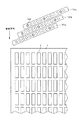
図12にインクジェット方式によるカラーフィルタの着色工程の様子を模式的に示す。図中、1は透明基板上に形成したブラックマトリクスであり、複数の開口部2を有している。当該工程では、少なくともこの開口部2にインクを付与して着色し、着色部を形成する。121a〜121cはそれぞれR、G、Bの各色のインクを付与するためのインクジェットヘッドであり、それぞれ複数のノズル122を直線状に配置してなる。各インクジェットヘッド121a〜121cは、図中の矢印方向に走査させながら各ノズルからインクを吐出するが、その際、インクジェットヘッドを走査方向に対して直交する方向に対して傾け、インクを吐出するノズルを選択する(図12においては4個おきのノズルを選択する)ことにより、選択したノズル122のピッチをカラーフィルタの同色の着色部の配列ピッチに対応させる。
【0005】
インクジェット方式によれば、図12に示したように、複数のノズルを備えたインクジェットヘッドをR、G、Bの各色に対応して複数本用いることで、複数色及び複数列の着色部を1走査で同時に着色することができる。さらに、当該走査を、インクジェットヘッドを走査方向とは直交する方向にずらしながら複数回行うことで、サイズの異なるカラーフィルタであっても、同じ装置で着色することができる。
【0006】
【発明が解決しようとする課題】
上記したように、インクジェット方式によるカラーフィルタの製造方法は、工程が簡易で異なるサイズにも容易に対応することができ、より安価にカラーフィルタを提供する方法として期待されるが、インクジェット特有の「発一性」という現象が生じる。「発一性」とは、インクの吐出までに時間を要した場合にノズル内のインクから水分等溶媒成分が蒸発して最初の一滴目のインク滴が濃くなってしまう現象を言い、結果として
▲1▼「よれ」と呼ばれる着弾精度の低下を招く、
▲2▼さらに、長時間を経過した場合、不吐(ノズルがインクを吐出しない)を生じる、
といった問題を生じてしまう。
【0007】
発一性はわずかな時間の経過でも生じ、吐出されたインクが基板上に着弾後、そのドット径が大きくなるため、隣接する異なる色に着色する領域にまでインクが及んでいわゆる「混色」の問題を引き起こす原因となる。また、上記したようによれを生じることによりさらに混色を引き起こすことになる。
【0008】
このような発一性による問題を解決する方法としては、吐出開始前に回復動作を行う、或いは、予備吐と呼ばれる操作を実施した後、できるだけ時間をあけずに着色工程を開始するものである。しかしながら、実際の着色工程においては、上記回復動作或いは予備吐を行った後、インクジェットヘッドと透明基板との位置合わせ(アライメント工程)が必要となり、このアライメント工程によって新たに発一性が生じる場合があった。
【0009】
そこで、次に考えられる発一性回避方法として、図13に示すように、液晶素子等を構成した際に表示に係る領域を有効領域として、少なくともその一端の外側に、表示に関与しない無効領域を設けておき、当該無効領域から走査することにより、本来のインク滴3よりも大きいドット径のインク滴131を無効領域で消費して有効領域への影響を防止する方法が挙げられる。この方法であれば、アライメント工程後に実施が可能で、回復動作または予備吐といった本来の着色工程以外の工程を省略して生産タクトを向上させることができる。尚、図13では開口部2にのみインクを付与しているが、図14に示すように、隣接する開口部2間にも連続してインクを付与する場合もある。
【0010】
しかしながら、無効領域を設けて発一性の影響を回避して作製されたカラーフィルタを用いて液晶素子を構成する際、カラーフィルタ上に透明導電膜であるITO膜を成膜する工程において、該無効領域が問題となる。具体的には、ITO膜はカラーフィルタ表面にメタルマスクを密着させて成膜されるが、メタルマスクはカラーフィルタの有効領域の周囲4辺よりもわずかに大きなサイズになっている。そのため、メタルマスクの4辺のエッジ部によって無効領域に形成された着色部が損傷してしまう。この無効領域は液晶素子の組立に際してそのまま残されるため、組立工程においてカラーフィルタが洗浄された場合、損傷部分から水が混入して有効領域の端部近傍の着色部の色が薄くなるといった問題を生じてしまう。
【0011】
そのため、無効領域はできるだけ狭くする方が好ましいが、混色は一度発生すると、発生箇所から走査方向に向けて一瞬に広がる傾向があり、無効領域が狭くなるほど混色は生じやすくなる。つまり、無効領域を狭くするほど、無効領域において発一性によって発生した混色が有効領域内に及ぶ可能性が増すことになる。特に、図14の如くライン状に連続してインクを付与した場合には、その可能性はより高くなるものと考えられる。
【0012】
本発明の課題は、上記問題点を解決し、インクジェット方式によるカラーフィルタの製造方法において、無効領域によって発一性の影響を回避すると同時に、該無効領域の幅を最小限にとどめて、液晶素子組立時の問題を抑制したカラーフィルタを提供することにあり、さらには、該カラーフィルタを用いて、カラー表示の液晶素子をより安価に提供することにある。
【0013】
【課題を解決するための手段】
本発明は、透明基板上に、インクジェット方式によりインクを付与して着色部を形成するカラーフィルタの製造方法であって、透明基板上の有効領域の少なくとも一端の外側に隣接して無効領域を設け、該無効領域より有効領域に向かって順次インクを付与し、且つ、前記インクを付与するための駆動パルスを前記無効領域と有効領域とで異ならせることにより該無効領域に付与するインク1滴あたりの量を有効領域よりも少なくすることを特徴とするカラーフィルタの製造方法である。
【0014】
上記本発明においては、下記の構成を好ましい態様として含むものである。
透明基板上に樹脂組成物からなるインク受容層を形成し、該インク受容層にインクジェット方式によりインクを付与して着色し、着色部を形成する。
透明基板上に複数の開口部を有する樹脂層を形成し、該樹脂層の開口部に硬化型インクを付与して硬化し、着色部を形成する。
【0016】
【発明の実施の形態】
本発明のカラーフィルタの製造方法は、無効領域におけるインク滴の吐出量を有効領域への吐出量よりも少なくすることにより、発一性を生じたインク滴のドット径を小さくして、その影響を抑制したことに特徴を有する。よって、本発明によれば、従来よりも狭い無効領域で発一性の影響を十分に回避することができる。
【0017】
本発明の製造方法における着色工程の様子を図1に模式的に示す。図中、1はブラックマトリクス、2はブラックマトリクス1の開口部、3〜5はインク滴である。本発明においては、カラーフィルタの表示領域の少なくとも一端、即ち着色工程の走査開始側に無効領域を設け、該無効領域より有効領域に向かって順次インクを付与する。この時、無効領域で付与するインク滴4の吐出量は、有効領域で付与するインク滴3の吐出量よりも少なくなるように設定する。これにより、発一性を生じたインク滴5のドット径も小さくなり、混色に対するその影響は大幅に抑制される。尚、インク滴4の吐出量をインク滴3よりも少なくした分、付与するインク滴数を増やすことで、単位面積当たりのインク付与量は有効領域と同等として高濃度になったインクの吐出を無効領域内において完了する。
【0018】
本発明にかかるインクジェット方式によるカラーフィルタの製造方法の基本工程について説明する。インクジェット方式によるカラーフィルタの製造方法には、▲1▼透明基板上に樹脂組成物からなるインク受容層を形成し、該インク受容層にインクジェット方式によりインクを付与して着色し、着色部を形成する方法と、▲2▼透明基板上に開口部を有する遮光層を形成し、該遮光層の開口部に硬化型インクを付与して硬化し、着色部を形成する方法とがある。先ず、上記▲1▼の方法について図2を用いて説明する。
【0019】
図2はインクジェット方式によるカラーフィルタの製造工程の一例を示す模式図であり、インクジェットヘッドの走査方向に対して直交する方向の断面模式図である。図中、10は透明基板、11は図1の2に相当するブラックマトリクス、12は樹脂組成物からなるインク受容層、13はフォトマスク、14は非着色部、15は被着色部、17はインク、18は着色部、19は保護層である。以下に各工程について説明するが、図2の(a)〜(d)はそれぞれ下記の工程(a)〜(d)に対応する断面模式図である。
【0020】
工程(a)
透明基板10上に、必要に応じてブラックマトリクス11を形成する。透明基板1としては、一般にガラスが用いられるが、カラーフィルタの透明性を損なわず、強度等必要な特性を備えたものであれば、プラスチック等も用いることができる。また、ブラックマトリクス11はブラックストライプでも良く、その膜厚は、通常0.1〜0.5μm程度であり、透明基板1上にクロム等金属をスパッタ或いは蒸着等により成膜し、フォトリソ工程によりパターニングして得られる。また、ブラックマトリクス11はインク受容層12上に形成しても良く、金属以外にも黒色樹脂等を用いて形成しても良い。
【0021】
尚、本製造工程においてブラックマトリクス11の開口部は、本発明に係る有効領域に形成されていれば良く、無効領域は液晶素子構成時に表示に関与しないため、当該開口部を形成する必要はない。むしろ、無効領域の表示への影響を防止する上では、該開口部を形成しない方が好ましい。
【0022】
次いで、透明基板10上に全面に樹脂組成物からなるインク受容層12を形成する。インク受容層12は、後述する工程において着色して着色部19を形成するための着色媒体であり、好ましくは、光照射或いは光照射と熱処理によってインク受容能が変化する感光性樹脂組成物で形成し、次工程においてパターン露光して混色防止のための非着色部14を形成する。感光性としては、ネガ型、ポジ型のいずれでも良く、具体的には、アクリル系樹脂、エポキシ系樹脂、シリコーン樹脂、ヒドロキシプロピルセルロース、ヒドロキシエチルセルロース、メチルセルロース、カルボキシメチルセルロースなどのセルロース誘導体或いはその変性物、アミド系樹脂、フェノール系樹脂、ポリスチレン系樹脂などが必要に応じて光開始剤(架橋剤)と併せて用いられる。光開始剤としては、重クロム酸塩、ビスアジド化合物、ラジカル系開始剤、カチオン系開始剤、アニオン系開始剤等が使用可能であり、さらには、これらの光開始剤を混合して、或いは他の増感剤と組み合わせて使用することができる。さらに、オニウム塩などの光酸発生剤を架橋剤として使用することも可能である。本実施形態は、光照射によりインク受容能を消失(或いは低減)する、ネガ型の樹脂組成物を用いた例を示す。
【0023】
上記感光性樹脂組成物は、スピンコート、ロールコート、バーコート、スプレーコート、ディップコート等の方法により透明基板10上に塗布し、必要に応じてプリベークしてインク受容層12とする。インク受容層12の厚さは、通常0.3〜3.0μm程度である。
【0024】
工程(b)
インク受容層12を感光性樹脂組成物で形成した場合には、フォトマスク13を用いて、インク受容層12をパターン露光し、露光部分のインク受容能を消失(或いは低減)せしめて非着色部14を形成する。非着色部14はブラックマトリクス11に重なる位置に形成され、特に、ブラックマトリクス11の開口部境界における白抜けを防止する観点から、ブラックマトリクス11の幅よりも非着色部14が狭くなるように形成することが好ましい。また、混色防止効果を高める上で、非着色部14が撥インク性を発現するような成分をインク受容層12に付与しておくことも好ましく適用される。
【0025】
当該工程において露光されなかった領域は被着色部15となる。また、露光によりインク受容能が発現(或いは増加)するポジ型の樹脂組成物を用いた場合には、逆のパターンで露光すればよい。
【0026】
工程(c)
インクジェットヘッド(不図示)より、所定の着色パターンに沿って、所定の色のインク17を被着色部15に吐出し、着色する。
【0027】
また、本発明においてインク受容層12の着色に用いられるインク17は、染料或いは顔料等着色剤を含有し、吐出時に液状であるものであれば、いずれでも好ましく用いられる。
【0028】
工程(d)
熱処理或いは光照射等必要な処理を施してインク受容層全体を硬化させ、非着色部14と着色部18からなる着色層を形成する。
【0029】
さらに、必要に応じて着色層上に保護層19を形成し、本発明のカラーフィルタを得る。保護層19は光硬化型、熱硬化型、或いは熱・光併用硬化型の樹脂組成物層、或いは蒸着、スパッタ等によって形成された無機膜等を用いることができる。いずれの場合もカラーフィルタとしての透明性を有し、その後のITO膜形成工程、配向膜形成工程等に耐えるものであれば使用することができる。
【0030】
次に、図3に前記▲2▼の製造方法の一例の工程を模式的に示す。図3は、図2と同様に、インクジェットヘッドの走査方向に対して直交する方向の断面模式図である。図中、31はブラックマトリクス、32は硬化型インク、33は着色部で、図1と同じ部材には同じ符号を付して説明を省略する。図3の(a)〜(c)はそれぞれ、下記工程(a)〜(c)に対応する断面図である。
【0031】
工程(a)
透明基板10上に、複数の開口部を有する樹脂層を形成する。該樹脂層は、インクを収納するための隔壁として作用する部材であり、本実施形態では該樹脂層を黒色樹脂で形成し、隣接する着色部33間を遮光する遮光層を兼ねたブラックマトリクス31とした例を示す。このようなブラックマトリクス31は、黒色顔料含有レジストを用い、一般的なフォトリソグラフィによりパターニングして形成することができる。また、ブラックマトリクス31には、後述するインクを吐出した際の混色を防止する上で撥インク性を付与しておくのが好ましい。ブラックマトリクス31の厚さは隔壁作用及び遮光作用を考慮すると0.5μm以上が好ましい。また、ブラックマトリクス31の素材としては、黒色顔料含有レジストの他に、クロム、酸化クロム等の金属或いは酸化金属膜を用いることができ、上記したように0.5μm以上の厚みを得るために、その上部にシリコーンゴム等の層を設けることが好ましい。
【0032】
尚、本製造工程においては、ブラックマトリクス31の開口部は後述する硬化型インク32を付与するために必要な凹部であるため、図2の工程とは異なり、当該開口部は本発明に係る無効領域にも形成する必要がある。
【0033】
工程(b)
ブラックマトリクス31の開口部を被着色部として、インクジェットヘッド(不図示)より、所定の着色パターンに沿って、所定の色の硬化型インク32を吐出する。
【0034】
本発明において用いられる硬化型インク32は、好ましくは硬化型着色樹脂組成物であり、少なくとも染料或いは顔料等着色剤と、熱処理或いは光照射等エネルギー付与により硬化する樹脂を含有している。例えば熱硬化型の樹脂組成物としては、公知の樹脂と架橋剤の組み合わせが使用でき、具体的には、メラミン樹脂、水酸基或いはカルボキシル基含有ポリマーとメラミン、水酸基或いはカルボキシル基含有ポリマーと多官能エポキシ化合物、水酸基或いはカルボキシル基含有ポリマーと繊維素反応型化合物、エポキシ樹脂とレゾール型樹脂、エポキシ樹脂とアミン類、エポキシ樹脂とカルボン酸または酸無水物、エポキシ化合物などが挙げられる。また、光硬化型樹脂組成物としては、市販のネガ型レジストが好適に用いられる。
【0035】
また、上記インクには、種々の溶媒を用いることができる。特に、インクジェット方式に用いる場合の吐出性の面から、水及び水溶性有機溶剤の混合溶媒が好ましく用いられる。
【0036】
さらに、上記成分の他に必要に応じて所望の特性を持たせるために、界面活性剤、消泡剤、防腐剤等を用いることができ、さらに、市販の水溶性染料などを添加することもできる。
【0037】
また、上記した光或いは熱硬化型樹脂のうち、水或いは水溶性有機溶剤に溶解しないものでも安定に吐出可能なものであれば、水や水溶性有機溶剤以外の溶媒を用いてもかまわない。また、特に光により重合するタイプの硬化性化合物を用いる場合には、染料をモノマーに溶解した無溶剤タイプとすることもできる。
【0038】
工程(c)
熱処理或いは光照射等必要な処理を施して硬化型インク32を硬化させ、着色部33を形成する。さらに、必要に応じて着色部33上に保護層19を形成し、本発明のカラーフィルタを得る。
【0039】
次に、図4にインクジェット方式を用いたカラーフィルタ製造装置の基本的な全体構成を模式的に示す。図中、41はカラーフィルタ製造装置、42は装置架台、43は装置架台42のXYθステージ(不図示)に載せられた基板、44は基板43上に形成された有効領域、45はR、G、Bの各色のインクを吐出するノズルを備えたインクジェットヘッドとこれらを支持するヘッドマウントとからなるヘッドユニット、47はカラーフィルタ製造装置41の全体動作を制御するコントローラ、48はコントローラ47の入出力手段であるティーチングペンダント(パーソナルコンピュータ)、49は製造の進行状況及びヘッドの異常の有無等情報を表示する表示部、50はカラーフィルタ製造装置41の動作を指示する操作部(キーボード)である。ヘッドユニット45は、カラーフィルタ製造装置41に着脱自在に、且つ、水平面内で回動角度を調整可能に装着されている。
【0040】
図5に、本発明において用いられるカラーフィルタ製造装置で使用されるインクジェットヘッドの一例の構造を模式的に示す。図中、51は加熱ヒータ、52はヒータボード、53は天板、54は吐出口、55は隔壁、56はインク液室、57はインク供給管、58は液路である。
【0041】
図5に示すように、本例のインクジェットヘッドは、インクを加熱するための複数の加熱ヒータ51が形成された基板であるヒータボード52と、このヒータボード52の上に被せられる天板53とから概略構成されている。天板53には、複数の吐出口54が形成されており、吐出口54の後方には、この吐出口54に連通するトンネル状の液路58が形成されている。各液路58は、隔壁55により隣接する液路58と隔絶されており、その後方において一つのインク液室56に共通に接続されている。インク液室56には、インク供給管57を介してインクが供給され、このインクはインク液室56からそれぞれの液路58に供給される。
【0042】
ヒータボード52と、天板53とは、各液路58に対応した位置に各加熱ヒータ51が配置するように位置合わせされて、図5のような状態に組み立てられる。図5においては、二つの加熱ヒータ51しか示されていないが、加熱ヒータ51は、それぞれの液路58に対応して一つずつ配置されている。図5の構成において、加熱ヒータ51に所定の駆動パルスを供給すると、加熱ヒータ51に接するインクが沸騰して気泡を発生し、この気泡の体積膨張によりインクが吐出口54から押し出されて吐出される。従って、加熱ヒータ51に加える駆動パルスを制御、例えば電圧値を制御することにより気泡の大きさを調整することが可能であり、吐出口54から吐出されるインクの体積を自在にコントロールすることができる。
【0043】
図6に上記インクジェットヘッドの駆動パルスの一例を示す。図中(a)はシングルパルス駆動、(b)はダブルパルス駆動の駆動波形である。(a)のシングルパルス駆動の場合、電圧或いはパルス幅を変化させることで吐出量を制御することができる。また、吐出量の制御幅と言った観点では、(b)のダブルパルス幅はより広く調整することが可能である。ここで、T1はプレパルス期間、T2は休止期間、T3はメインパルス期間である。シングルパルス駆動に比べてダブルパルス駆動が効率的な理由としては、ヒータの発熱量はその表面に触れたインクに一部吸収されるため、プレパルスを投入することでインク自体の温度をある程度温めておき、その後のメインパルスでの発泡を助けることができるためである。本発明においては、例えば、吐出量を広く調整することが可能なダブルパルス駆動でプレパルスを短くすることで、無効領域に付与するインク滴の吐出量を少なくすることができる。
【0044】
次に、ダブルパルス駆動において実際にT1を選択して吐出量を制御する手段の一例を示す。
【0045】
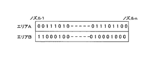
図7に示したように、ノズルに対応した2ビットのデータがインクジェットヘッドを制御するコントロールボードのROMエリアA及びBに書き込まれている。この2ビットのデータで図8に示す4種類のパルス幅T1が選択可能であるものとする。例えば、ノズル番号1、2は(0,1)であるからPH2の、ノズル番号3は(1,0)であるからPH3のT1パルス幅が選択される。
【0046】
このように、インクジェットヘッドからのインクの吐出が開始される前にT1選択ビットにより各ノズルのT1パルス幅が選択される。その後、所定のメインパルスが印加される。吐出量制御は、吐出量を変更したい所望の位置でT1選択ビットを書き換えることで実施できる。
【0047】
図9に当該駆動を実施しうる電気回路構成を示す。図中、信号線VHはインクジェットヘッドの電源、HGNDはVHに対するGND線、MHはT3期間に印加されるメインパルスの信号線、PH1〜PH4は先に示したプレパルスの信号線、BLATはPH1〜PH4を選択するためのビットデータをラッチするための信号線、DLATはインク吐出に必要なデータ(吐出パターンデータ)をラッチするための信号線、DATAはビットデータ及び吐出パターンデータがシリアルデータとして転送され、シフトレジスタに確認される信号線である。
【0048】
図9の構成において、図7で示したビットデータ(選択ビット)がシリアルデータとしてDATA信号線からシフトレジスタに格納される。全ノズルのビットデータが揃ったところで、BLAT信号が発生し、ビットデータがラッチされる。
【0049】
次に、着色に必要な吐出パターンデータが同様にDATA信号からシフトレジスタに格納される。全ノズルのデータが揃ったところでDLAT信号が発生してデータがラッチされる。先にラッチされたビットデータから選択論理回路を通してPH1〜PH4の何れかが選択される。選択されたPH信号とメインパルス信号MHが合成されて、さらに、吐出パターンデータとANDをとってノズルnのトランジスタが駆動され、抵抗(ヒータボード)にVHが印加されてノズルからインクが吐出する。
【0050】
このような操作が全ノズルにおいてなされる。PH信号とMH信号が合成される様子は図10に示すとおりである。また、吐出量を変更した所望のタイミングで新たなビットデータをシフトレジスタに送り、BLAT信号を発生させることにより吐出量の制御は可能である。
【0051】
尚、ここでは、2ビットを使用して4種類のPHパルスを選択可能としているが、1ビットを使用して2種類の選択としても本発明を実施することが可能である。また、さらに、ビット数を増やすことでより細かい吐出量制御が可能であるが、その反面、選択論理回路構成が複雑になる。
【0052】
上記説明においては、インクジェットヘッドとしてバブルジェットヘッドを用いた例を示したが、これ以外にも、インクを吐出させる圧力発生手段として、静電吸引力や、圧電素子による変形等を利用した手段が挙げられる。また、こうしたヘッドに関して、図6に示した駆動パルスを適宜考慮することで吐出量を制御することが可能である。
【0053】
次に、図11に本発明の液晶素子の一実施形態の断面模式図を示す。本実施形態は、図2の工程により得られた本発明のカラーフィルタを用いて、TFT型カラー液晶素子を構成した例である。図中、111は共通電極、112,117は配向膜、113は液晶、115は対向基板、116は画素電極であり、図2と同じ部材には同じ符号を付して説明を省略する。
【0054】
カラー液晶素子は、一般的にカラーフィルタ側の基板10と対向基板115とを合わせ込み、液晶113を封入することにより形成される。液晶素子の一方の基板115の内側に、TFT(不図示)と画素電極116がマトリクス状に形成されている。また、カラーフィルタ側の基板10の内側には、画素電極116に対向する位置に、R、G、Bが配列するように、カラーフィルタの着色部18が形成され、その上に透明な共通電極111が形成される。ブラックマトリクス11は、通常カラーフィルタ側に形成されるが、BMオンアレイタイプの液晶素子等では対向基板115側に形成される場合もある。さらに、両基板の面内には配向膜112,117が形成されており、液晶分子を一定方向に配列させている。これらの基板は、スペーサー(不図示)を介して対向配置され、シール材(不図示)によって貼り合わされ、その間隙に液晶113が充填される。
【0055】
上記液晶素子は、透過型の場合には、基板115及び画素電極116を透明素材で形成し、それぞれの基板の外側に偏光板を接着し、一般的に蛍光灯と散乱板を組み合わせたバックライトを用い、液晶化合物をバックライトの光の透過率を変化させる光シャッターとして機能させることにより表示を行う。また、反射型の場合には、基板115或いは画素電極116を反射機能を備えた素材で形成するか、或いは、基板115上に反射層を設け、透明基板10の外側に偏光板を設け、カラーフィルタ側から入射した光を反射して表示を行う。
【0056】
また、本発明の液晶素子においては、本発明のカラーフィルタを用いて構成されていれば、他の部材については従来の技術をそのまま用いることができることは言うまでもない。
【0057】
【発明の効果】
以上説明したように、本発明によれば、インクジェット方式において問題となる「発一性」をタクトに影響することなく回避し、それによる混色の発生を防ぐことができる。また、本発明を利用すれば、無効領域の狭いカラーフィルタにも対応することができ、信頼性の高いカラー表示の液晶素子をより安価に提供することが可能となる。
【図面の簡単な説明】
【図1】本発明のカラーフィルタの製造方法における着色工程を模式的に示す平面図である。
【図2】インクジェット方式によるカラーフィルタの製造工程の一例を示す断面模式図である。
【図3】インクジェット方式によるカラーフィルタの製造工程の他の例を示す断面模式図である。
【図4】インクジェット方式を用いたカラーフィルタ製造装置の基本的な全体構成の模式図である。
【図5】本発明において用いられるカラーフィルタ製造装置で使用されるインクジェットヘッドの一例の構造を模式的に示す図である。
【図6】インクジェットヘッドの駆動パルスの一例を示す図である。
【図7】図6のダブルパルス駆動波形におけるプレパルスの選択ビットを示す図である。
【図8】図7の選択ビットにより選択可能なプレパルスの波形を示す図である。
【図9】図6〜図8に示したダブルパルス駆動を実施しうる電気回路構成を示す図である。
【図10】図9におけるPH信号とMH信号の合成を示す図である。
【図11】本発明の液晶素子の一実施形態の断面模式図である。
【図12】インクジェット方式によるカラーフィルタの着色工程の様子を示す平面模式図である。
【図13】発一性回避手段として無効領域を設けた場合の着色工程の様子を示す平面模式図である。
【図14】発一性回避手段として無効領域を設けた場合の着色工程の他の例の様子を示す平面模式図である。
【符号の説明】
1 ブラックマトリクス
2 開口部
3、4、5 インク滴
10 透明基板
11、31 ブラックマトリクス
12 インク受容層
13 フォトマスク
14 非着色部
15 被着色部
17 インク
18、33 着色部
19 保護層
32 硬化型インク
41 カラーフィルタ製造装置
42 装置架台
43 基板
44 有効領域
45 ヘッドユニット
47 コントローラ
48 ティーチングペンダント
49 表示部
50 操作部
51 加熱ヒータ
52 ヒータボード
53 天板
54 吐出口
55 隔壁
56 インク液室
57 インク供給管
58 液路
111 共通電極
112、117 配向膜
113 液晶
115 対向基板
116 画素電極
121a〜121c インクジェットヘッド
122 ノズル
131 インク滴[0001]
BACKGROUND OF THE INVENTION
The present invention relates to a liquid crystal element for color display used in a color television, a personal computer, a pachinko game machine or the like, a color filter which is a constituent member of the liquid crystal element, and a method for manufacturing the same.
[0002]
[Prior art]
In recent years, with the development of personal computers, in particular with the development of portable personal computers, the demand for color liquid crystal displays tends to increase. However, for further widespread use, there is an increasing demand for cost reduction of color filters that are particularly high in cost.
[0003]
Conventionally, methods for producing a color filter include a pigment dispersion method, a dyeing method, an electrodeposition method, and a printing method. Recently, an ink jet method has been developed. The ink jet method is a method in which a colored portion is formed by applying ink on a transparent substrate using an ink jet recording apparatus, but there are a plurality of colors, usually red (R), green (G), and blue (B). A plurality of colors can be colored in one step by simultaneously applying color inks onto a transparent substrate.
[0004]
FIG. 12 schematically shows the state of the color filter coloring process by the ink jet method. In the figure,
[0005]
According to the ink jet system, as shown in FIG. 12, by using a plurality of ink jet heads having a plurality of nozzles corresponding to the respective colors of R, G, and B, a plurality of colors and a plurality of rows of colored portions are provided. It can be colored simultaneously by scanning. Furthermore, by performing the scanning a plurality of times while shifting the inkjet head in a direction orthogonal to the scanning direction, even color filters having different sizes can be colored with the same apparatus.
[0006]
[Problems to be solved by the invention]
As described above, the method for producing a color filter by the ink jet method is simple as a process, can easily cope with different sizes, and is expected as a method for providing a color filter at a lower cost. The phenomenon of “unification” occurs. “Uniformity” refers to a phenomenon in which a solvent component such as moisture evaporates from the ink in the nozzle when time is required until the ink is ejected, and the first ink droplet becomes darker.
▲ 1 ▼ Invitation accuracy is reduced, which is called “yore”.
(2) Further, when a long time has passed, non-discharge (no nozzle does not discharge ink) occurs.
Will cause problems.
[0007]
Uniformity occurs even after a short period of time, and after the ejected ink has landed on the substrate, its dot diameter increases, so that the ink extends to adjacent different colored areas, so-called `` mixed color '' Cause problems. Further, color mixing is caused by causing the above-described kinking.
[0008]
As a method of solving such a problem due to the uniformity, the coloring process is started with as little time as possible after performing a recovery operation before starting the discharge or performing an operation called preliminary discharge. . However, in the actual coloring process, after performing the recovery operation or preliminary ejection, it is necessary to align the inkjet head and the transparent substrate (alignment process). there were.
[0009]
Therefore, as a possible method for avoiding the uniformity, as shown in FIG. 13, when the liquid crystal element or the like is configured, an area related to display is set as an effective area, and at least outside one end thereof, an ineffective area not related to display is displayed. And by scanning from the invalid area, an
[0010]
However, when a liquid crystal element is formed using a color filter manufactured by avoiding the influence of uniformity by providing an ineffective region, in the step of forming an ITO film that is a transparent conductive film on the color filter, Invalid areas become a problem. Specifically, the ITO film is formed by bringing a metal mask into close contact with the surface of the color filter, but the metal mask has a size slightly larger than the four sides around the effective area of the color filter. For this reason, the colored portion formed in the invalid region is damaged by the edge portions of the four sides of the metal mask. Since this invalid area is left as it is during the assembly of the liquid crystal element, when the color filter is washed in the assembly process, water is mixed from the damaged part and the color of the colored part near the end of the effective area becomes light. It will occur.
[0011]
For this reason, it is preferable to make the invalid area as narrow as possible. However, once color mixing occurs, there is a tendency to spread instantaneously from the location of occurrence toward the scanning direction, and color mixing tends to occur as the invalid area becomes narrower. In other words, the narrower the invalid area, the more likely the mixed color generated in the invalid area due to the uniformity is in the effective area. In particular, when ink is continuously applied in a line shape as shown in FIG. 14, the possibility is considered to be higher.
[0012]
An object of the present invention is to solve the above-mentioned problems, and in the method of manufacturing a color filter by an ink jet method, while avoiding the influence of the uniformity by the ineffective region, the width of the ineffective region is minimized, and the liquid crystal element The object of the present invention is to provide a color filter that suppresses problems during assembly, and to provide a liquid crystal element for color display at a lower cost by using the color filter.
[0013]
[Means for Solving the Problems]
Main departure Tomorrow A color filter manufacturing method for forming a colored portion by applying ink by an ink jet method on a transparent substrate, wherein an ineffective region is provided adjacent to the outside of at least one end of the effective region on the transparent substrate. Ink that is applied to the invalid area by sequentially applying ink from the area toward the effective area and making the drive pulse for applying the ink different between the invalid area and the effective area Per drop A color filter manufacturing method characterized in that the amount is less than the effective area.
[0014]
In the said invention, the following structure is included as a preferable aspect.
An ink receiving layer made of a resin composition is formed on a transparent substrate, and the ink receiving layer is colored by applying ink by an ink jet method to form a colored portion.
A resin layer having a plurality of openings is formed on a transparent substrate, and a curable ink is applied to the openings of the resin layer and cured to form colored portions.
[0016]
DETAILED DESCRIPTION OF THE INVENTION
The method of manufacturing a color filter of the present invention reduces the dot diameter of the ink droplets that cause the unidirectionality by reducing the ejection amount of the ink droplets in the ineffective region to be smaller than the ejection amount to the effective region, and the influence thereof. It has the feature in having suppressed. Therefore, according to the present invention, it is possible to sufficiently avoid the influence of the uniformity in the ineffective area narrower than the conventional one.
[0017]
The state of the coloring step in the production method of the present invention is schematically shown in FIG. In the figure, 1 is a black matrix, 2 is an opening of the
[0018]
The basic process of the color filter manufacturing method according to the present invention will be described. In the method of manufacturing a color filter by an ink jet method, (1) an ink receiving layer made of a resin composition is formed on a transparent substrate, and ink is applied to the ink receiving layer by an ink jet method to form a colored portion. And (2) a method of forming a light-shielding layer having an opening on a transparent substrate, applying a curable ink to the opening of the light-shielding layer, and curing to form a colored portion. First, the above method (1) will be described with reference to FIG.
[0019]
FIG. 2 is a schematic diagram illustrating an example of a manufacturing process of a color filter by an inkjet method, and is a schematic cross-sectional view in a direction orthogonal to the scanning direction of the inkjet head. In the figure, 10 is a transparent substrate, 11 is a black matrix corresponding to 2 in FIG. 1, 12 is an ink receiving layer made of a resin composition, 13 is a photomask, 14 is a non-colored portion, 15 is a colored portion, and 17 is a colored portion. Ink, 18 is a colored portion, and 19 is a protective layer. Each step will be described below. FIGS. 2A to 2D are schematic cross-sectional views corresponding to the following steps (a) to (d), respectively.
[0020]
Step (a)
A
[0021]
In the present manufacturing process, the opening of the
[0022]
Next, an
[0023]
The photosensitive resin composition is applied onto the
[0024]
Step (b)
When the
[0025]
A region that has not been exposed in this process becomes the
[0026]
Step (c)
From an inkjet head (not shown),
[0027]
In the present invention, the
[0028]
Step (d)
Necessary processing such as heat treatment or light irradiation is performed to cure the entire ink receiving layer, and a colored layer composed of the
[0029]
Furthermore, a
[0030]
Next, FIG. 3 schematically shows an example of the manufacturing method of (2). FIG. 3 is a schematic cross-sectional view in the direction orthogonal to the scanning direction of the inkjet head, as in FIG. In the figure, 31 is a black matrix, 32 is a curable ink, 33 is a colored portion, and the same members as those in FIG. 3A to 3C are cross-sectional views corresponding to the following steps (a) to (c), respectively.
[0031]
Step (a)
A resin layer having a plurality of openings is formed on the
[0032]
In this manufacturing process, since the opening of the
[0033]
Step (b)
A
[0034]
The
[0035]
Various solvents can be used for the ink. In particular, a mixed solvent of water and a water-soluble organic solvent is preferably used from the viewpoint of dischargeability when used in an inkjet method.
[0036]
In addition to the above components, surfactants, antifoaming agents, preservatives, and the like can be used to give desired properties as required, and commercially available water-soluble dyes can also be added. it can.
[0037]
In addition, among the light or thermosetting resins described above, a solvent other than water or a water-soluble organic solvent may be used as long as it can be stably discharged even if it is not dissolved in water or a water-soluble organic solvent. In particular, when a curable compound that is polymerized by light is used, a solventless type in which a dye is dissolved in a monomer may be used.
[0038]
Step (c)
Necessary processing such as heat treatment or light irradiation is performed to cure the
[0039]
Next, FIG. 4 schematically shows a basic overall configuration of a color filter manufacturing apparatus using an ink jet method. In the figure, 41 is a color filter manufacturing apparatus, 42 is an apparatus base, 43 is a substrate placed on an XYθ stage (not shown) of the
[0040]
FIG. 5 schematically shows an example of the structure of an ink jet head used in the color filter manufacturing apparatus used in the present invention. In the figure, 51 is a heater, 52 is a heater board, 53 is a top plate, 54 is a discharge port, 55 is a partition, 56 is an ink liquid chamber, 57 is an ink supply pipe, and 58 is a liquid path.
[0041]
As shown in FIG. 5, the ink jet head of this example includes a
[0042]
The
[0043]
FIG. 6 shows an example of driving pulses for the ink jet head. In the figure, (a) shows the driving waveform of single pulse driving, and (b) shows the driving waveform of double pulse driving. In the case of the single pulse drive of (a), the discharge amount can be controlled by changing the voltage or the pulse width. Further, from the viewpoint of the discharge amount control width, the double pulse width of (b) can be adjusted wider. Where T 1 Is the prepulse period, T 2 Is the suspension period, T Three Is the main pulse period. The reason why double pulse driving is more efficient than single pulse driving is that the amount of heat generated by the heater is partially absorbed by the ink that touches the surface of the heater. This is because it can help foaming in the main pulse thereafter. In the present invention, for example, by shortening the pre-pulse by double pulse driving capable of widely adjusting the discharge amount, it is possible to reduce the discharge amount of the ink droplets applied to the invalid area.
[0044]
Next, in the double pulse drive, the actual T 1 An example of means for controlling the discharge amount by selecting is shown.
[0045]
As shown in FIG. 7, 2-bit data corresponding to the nozzle is written in the ROM areas A and B of the control board for controlling the inkjet head. With this 2-bit data, four types of pulse widths T shown in FIG. 1 Is selectable. For example, since
[0046]
In this way, before the ejection of ink from the inkjet head is started, T 1 The T of each nozzle is selected by the selection bit. 1 The pulse width is selected. Thereafter, a predetermined main pulse is applied. The discharge amount control is performed at a desired position where the discharge amount is desired to be changed. 1 This can be done by rewriting the selection bit.
[0047]
FIG. 9 shows an electric circuit configuration capable of performing the driving. In the figure, the signal line VH is the power source of the inkjet head, H GND Is the GND line for VH, MH is T Three The signal line of the main pulse applied during the period, PH 1 ~ PH Four Is the pre-pulse signal line B LAT Is PH 1 ~ PH Four A signal line for latching bit data for selecting D, LAT Is a signal line for latching data necessary for ink ejection (ejection pattern data), and DATA is a signal line to which bit data and ejection pattern data are transferred as serial data and confirmed by a shift register.
[0048]
In the configuration of FIG. 9, the bit data (selection bit) shown in FIG. 7 is stored as serial data from the DATA signal line to the shift register. When the bit data of all nozzles is ready, B LAT A signal is generated and the bit data is latched.
[0049]
Next, ejection pattern data necessary for coloring is similarly stored from the DATA signal into the shift register. D when all nozzle data is available LAT A signal is generated and data is latched. PH from the previously latched bit data through the selection logic circuit 1 ~ PH Four Is selected. The selected PH signal and the main pulse signal MH are combined, and the AND of the ejection pattern data and the transistor of the nozzle n are driven, and VH is applied to the resistor (heater board) to eject ink from the nozzle. .
[0050]
Such an operation is performed for all nozzles. The manner in which the PH signal and the MH signal are combined is as shown in FIG. Also, new bit data is sent to the shift register at the desired timing when the discharge amount is changed, and B LAT The discharge amount can be controlled by generating a signal.
[0051]
Here, four types of PH pulses can be selected using 2 bits, but the present invention can also be implemented as two types of selection using 1 bit. In addition, finer discharge amount control is possible by increasing the number of bits, but on the other hand, the selection logic circuit configuration is complicated.
[0052]
In the above description, an example in which a bubble jet head is used as an inkjet head has been shown. However, in addition to this, as a pressure generating means for ejecting ink, there are means using electrostatic attraction force, deformation by a piezoelectric element, or the like. Can be mentioned. Further, with respect to such a head, the ejection amount can be controlled by appropriately considering the drive pulses shown in FIG.
[0053]
Next, FIG. 11 shows a schematic cross-sectional view of one embodiment of the liquid crystal element of the present invention. The present embodiment is an example in which a TFT color liquid crystal element is configured using the color filter of the present invention obtained by the process of FIG. In the figure, 111 is a common electrode, 112 and 117 are alignment films, 113 is a liquid crystal, 115 is a counter substrate, and 116 is a pixel electrode. The same members as those in FIG.
[0054]
The color liquid crystal element is generally formed by combining the
[0055]
When the liquid crystal element is a transmissive type, a backlight in which a
[0056]
In addition, in the liquid crystal element of the present invention, it is needless to say that the conventional technique can be used as it is for other members as long as the liquid crystal element of the present invention is configured.
[0057]
【The invention's effect】
As described above, according to the present invention, “uniformity” that is a problem in the ink jet system can be avoided without affecting the tact, and color mixing due to this can be prevented. In addition, if the present invention is used, it is possible to deal with a color filter with a narrow invalid area, and it is possible to provide a liquid crystal element with high reliability for color display at a lower cost.
[Brief description of the drawings]
FIG. 1 is a plan view schematically showing a coloring step in a method for producing a color filter of the present invention.
FIG. 2 is a schematic cross-sectional view showing an example of a manufacturing process of a color filter by an ink jet method.
FIG. 3 is a schematic cross-sectional view showing another example of the manufacturing process of the color filter by the ink jet method.
FIG. 4 is a schematic diagram of a basic overall configuration of a color filter manufacturing apparatus using an inkjet method.
FIG. 5 is a diagram schematically showing an example of the structure of an ink jet head used in the color filter manufacturing apparatus used in the present invention.
FIG. 6 is a diagram illustrating an example of a drive pulse of an inkjet head.
7 is a diagram showing pre-pulse selection bits in the double-pulse drive waveform of FIG. 6; FIG.
8 is a diagram showing waveforms of prepulses that can be selected by a selection bit in FIG. 7;
FIG. 9 is a diagram showing an electric circuit configuration capable of implementing the double pulse driving shown in FIGS.
10 is a diagram illustrating synthesis of a PH signal and an MH signal in FIG. 9. FIG.
FIG. 11 is a schematic cross-sectional view of an embodiment of a liquid crystal element of the present invention.
FIG. 12 is a schematic plan view showing a state of a color filter coloring process by an inkjet method.
FIG. 13 is a schematic plan view showing a state of a coloring process when an invalid area is provided as a means for avoiding the uniformity.
FIG. 14 is a schematic plan view showing another example of the coloring process when an invalid area is provided as a means for avoiding the uniformity.
[Explanation of symbols]
1 Black matrix
2 opening
3, 4, 5 ink drops
10 Transparent substrate
11, 31 Black matrix
12 Ink receiving layer
13 Photomask
14 Uncolored part
15 Colored part
17 ink
18, 33 Coloring part
19 Protective layer
32 curable ink
41 Color filter manufacturing equipment
42 Equipment stand
43 substrates
44 Effective area
45 head unit
47 Controller
48 Teaching pendant
49 Display
50 Operation unit
51 Heater
52 Heater board
53 Top plate
54 Discharge port
55 Bulkhead
56 Ink chamber
57 Ink supply tube
58 Fluid path
111 Common electrode
112, 117 Alignment film
113 LCD
115 Counter substrate
116 pixel electrodes
121a to 121c inkjet head
122 nozzles
131 Ink drops
Claims (3)
Priority Applications (1)
| Application Number | Priority Date | Filing Date | Title |
|---|---|---|---|
| JP2001039434A JP4663138B2 (en) | 2001-02-16 | 2001-02-16 | Manufacturing method of color filter |
Applications Claiming Priority (1)
| Application Number | Priority Date | Filing Date | Title |
|---|---|---|---|
| JP2001039434A JP4663138B2 (en) | 2001-02-16 | 2001-02-16 | Manufacturing method of color filter |
Publications (3)
| Publication Number | Publication Date |
|---|---|
| JP2002243928A JP2002243928A (en) | 2002-08-28 |
| JP2002243928A5 JP2002243928A5 (en) | 2008-03-27 |
| JP4663138B2 true JP4663138B2 (en) | 2011-03-30 |
Family
ID=18902223
Family Applications (1)
| Application Number | Title | Priority Date | Filing Date |
|---|---|---|---|
| JP2001039434A Expired - Fee Related JP4663138B2 (en) | 2001-02-16 | 2001-02-16 | Manufacturing method of color filter |
Country Status (1)
| Country | Link |
|---|---|
| JP (1) | JP4663138B2 (en) |
Families Citing this family (1)
| Publication number | Priority date | Publication date | Assignee | Title |
|---|---|---|---|---|
| JP4561226B2 (en) * | 2004-08-06 | 2010-10-13 | セイコーエプソン株式会社 | Color filter deposition method |
Citations (2)
| Publication number | Priority date | Publication date | Assignee | Title |
|---|---|---|---|---|
| JPH09101410A (en) * | 1995-07-14 | 1997-04-15 | Canon Inc | Manufacture of color filter and manufacturing device and color filter and color filter substrate and display device and device equipped with this display device |
| JPH10186123A (en) * | 1996-12-26 | 1998-07-14 | Asahi Glass Co Ltd | Manufacture of color filter, and color filter |
-
2001
- 2001-02-16 JP JP2001039434A patent/JP4663138B2/en not_active Expired - Fee Related
Patent Citations (2)
| Publication number | Priority date | Publication date | Assignee | Title |
|---|---|---|---|---|
| JPH09101410A (en) * | 1995-07-14 | 1997-04-15 | Canon Inc | Manufacture of color filter and manufacturing device and color filter and color filter substrate and display device and device equipped with this display device |
| JPH10186123A (en) * | 1996-12-26 | 1998-07-14 | Asahi Glass Co Ltd | Manufacture of color filter, and color filter |
Also Published As
| Publication number | Publication date |
|---|---|
| JP2002243928A (en) | 2002-08-28 |
Similar Documents
| Publication | Publication Date | Title |
|---|---|---|
| JP3124722B2 (en) | Method and apparatus for manufacturing color filter, method of reducing color mixture between partitioned areas of color filter, method of improving accuracy of ink application position to partitioned area of color filter, and coloring unevenness of partitioned area of color filter Reduction method | |
| US6145981A (en) | Color filter manufacturing method and apparatus, color filter, color filter substrate, display device, and apparatus having display device | |
| KR100388183B1 (en) | Color filter producing method and apparatus | |
| US6341862B1 (en) | Color filter, method of producing the same and liquid crystal display device | |
| JP2000089017A (en) | Color filter, its production, device therefor and liquid crystal device using said color filter | |
| JP2941247B2 (en) | Method for setting ink ejection density, method for manufacturing color filter, method for manufacturing display device, and method for manufacturing device equipped with display device | |
| US6692095B1 (en) | Color filter manufacturing method, color filter, display device, and apparatus having display device | |
| JP2000089019A (en) | Color filter and production thereof, liquid crystal element using the filter | |
| JP2003066218A (en) | Method for repairing defect in color filter | |
| JP2001083528A (en) | Liquid crystal device, its production, substrate with spacer and its production | |
| JP4065475B2 (en) | Color filter manufacturing method, liquid crystal element using the color filter manufactured by this manufacturing method, and inkjet head | |
| JP2001147316A (en) | Color filter, method of producing the same and liquid crystal device using that color filter | |
| JP3762187B2 (en) | Color filter manufacturing method, color filter manufacturing device, and display device manufacturing method including color filter | |
| JPH08327811A (en) | Ink for color filter, color filter, production of color filter and liquid crystal panel | |
| JP3332812B2 (en) | Method for manufacturing color filter, method for manufacturing display device, and method for manufacturing device equipped with display device | |
| JP4663138B2 (en) | Manufacturing method of color filter | |
| JP2000089020A (en) | Color filter, manufacture thereof, and liquid crystal element using the color filter | |
| JP4438039B2 (en) | Color filter manufacturing method and manufacturing apparatus, liquid crystal panel manufacturing method, display device manufacturing method, display device panel manufacturing method | |
| JP4636648B2 (en) | Manufacturing method of color filter | |
| JP2001154008A (en) | Color filter, method of producing the same, liquid crystal device using the color filter | |
| JPH08327998A (en) | Ink for color filter, color filter, production of color filter and liquid crystal panel | |
| JP2001133622A (en) | Method and device for producing color filter, method for decreasing color mixing between pixels in color filter, method for improving precision of ink deposition point on pixel of color filter, and method for producing display device | |
| JP2001183514A (en) | Color filter and its manufacturing method, liquid crystal element using color filter | |
| JPH1164626A (en) | Method and device for manufacturing color filter, color filter, display device and device provided with the display device | |
| JP2002303715A (en) | Color filter and method for manufacturing the same, liquid crystal element using the color filter |
Legal Events
| Date | Code | Title | Description |
|---|---|---|---|
| A521 | Written amendment |
Free format text: JAPANESE INTERMEDIATE CODE: A523 Effective date: 20080206 |
|
| A621 | Written request for application examination |
Free format text: JAPANESE INTERMEDIATE CODE: A621 Effective date: 20080206 |
|
| A977 | Report on retrieval |
Free format text: JAPANESE INTERMEDIATE CODE: A971007 Effective date: 20100629 |
|
| A131 | Notification of reasons for refusal |
Free format text: JAPANESE INTERMEDIATE CODE: A131 Effective date: 20100706 |
|
| A521 | Written amendment |
Free format text: JAPANESE INTERMEDIATE CODE: A523 Effective date: 20100902 |
|
| A131 | Notification of reasons for refusal |
Free format text: JAPANESE INTERMEDIATE CODE: A131 Effective date: 20101019 |
|
| A521 | Written amendment |
Free format text: JAPANESE INTERMEDIATE CODE: A523 Effective date: 20101207 |
|
| TRDD | Decision of grant or rejection written | ||
| A01 | Written decision to grant a patent or to grant a registration (utility model) |
Free format text: JAPANESE INTERMEDIATE CODE: A01 Effective date: 20101228 |
|
| A01 | Written decision to grant a patent or to grant a registration (utility model) |
Free format text: JAPANESE INTERMEDIATE CODE: A01 |
|
| A61 | First payment of annual fees (during grant procedure) |
Free format text: JAPANESE INTERMEDIATE CODE: A61 Effective date: 20110105 |
|
| R150 | Certificate of patent or registration of utility model |
Free format text: JAPANESE INTERMEDIATE CODE: R150 |
|
| FPAY | Renewal fee payment (event date is renewal date of database) |
Free format text: PAYMENT UNTIL: 20140114 Year of fee payment: 3 |
|
| LAPS | Cancellation because of no payment of annual fees |