JP4661516B2 - Fixing device and fixing belt deterioration judging method - Google Patents

Fixing device and fixing belt deterioration judging method Download PDF

Info

Publication number
JP4661516B2
JP4661516B2 JP2005306318A JP2005306318A JP4661516B2 JP 4661516 B2 JP4661516 B2 JP 4661516B2 JP 2005306318 A JP2005306318 A JP 2005306318A JP 2005306318 A JP2005306318 A JP 2005306318A JP 4661516 B2 JP4661516 B2 JP 4661516B2
Authority
JP
Japan
Prior art keywords
fixing
fixing belt
belt
unit
recording material
Prior art date
Legal status (The legal status is an assumption and is not a legal conclusion. Google has not performed a legal analysis and makes no representation as to the accuracy of the status listed.)
Expired - Fee Related
Application number
JP2005306318A
Other languages
Japanese (ja)
Other versions
JP2007114524A5 (en
JP2007114524A (en
Inventor
康隆 内藤
秀明 大原
Current Assignee (The listed assignees may be inaccurate. Google has not performed a legal analysis and makes no representation or warranty as to the accuracy of the list.)
Fujifilm Business Innovation Corp
Original Assignee
Fuji Xerox Co Ltd
Fujifilm Business Innovation Corp
Priority date (The priority date is an assumption and is not a legal conclusion. Google has not performed a legal analysis and makes no representation as to the accuracy of the date listed.)
Filing date
Publication date
Application filed by Fuji Xerox Co Ltd, Fujifilm Business Innovation Corp filed Critical Fuji Xerox Co Ltd
Priority to JP2005306318A priority Critical patent/JP4661516B2/en
Publication of JP2007114524A publication Critical patent/JP2007114524A/en
Publication of JP2007114524A5 publication Critical patent/JP2007114524A5/ja
Application granted granted Critical
Publication of JP4661516B2 publication Critical patent/JP4661516B2/en
Expired - Fee Related legal-status Critical Current
Anticipated expiration legal-status Critical

Links

Images

Description

本発明は、例えば電子写真方式を利用した画像形成装置において記録材にトナー画像を定着する定着装置等に関する。   The present invention relates to a fixing device that fixes a toner image on a recording material in an image forming apparatus using, for example, an electrophotographic system.

例えば電子写真方式を採用した複写機、プリンタ、ファクシミリ等の画像形成装置では、例えばドラム状に形成された感光体(感光体ドラム)を一様に帯電し、帯電された感光体ドラムを画像情報に基づいて制御された光で露光して感光体ドラム上に静電潜像を形成する。次いで、感光体ドラム上に形成された静電潜像をトナーによって現像して可視像(トナー像)化し、このトナー像を直接または中間転写体等を介して間接的に用紙に転写する。そして、用紙に転写されたトナー像(未定着トナー像)を、定着装置によって用紙に定着している。   For example, in an image forming apparatus such as a copying machine, printer, or facsimile employing an electrophotographic system, for example, a drum-shaped photosensitive member (photosensitive drum) is uniformly charged, and the charged photosensitive drum is subjected to image information. And an electrostatic latent image is formed on the photosensitive drum by exposure with light controlled based on the above. Next, the electrostatic latent image formed on the photosensitive drum is developed with toner to form a visible image (toner image), and the toner image is directly or indirectly transferred to a sheet via an intermediate transfer member or the like. The toner image (unfixed toner image) transferred to the paper is fixed on the paper by a fixing device.

上述した定着装置としては、例えば回動する加熱部材と、この加熱部材に回動可能に圧接配置される加圧部材とを備えたものが広く用いられている。このような定着装置では、加熱部材と加圧部材とのニップ部(定着ニップ部)に用紙を挟み込んで挿通させ、トナー像を加熱溶融して用紙に圧着している。特に、最近では、加熱部材に金属等からなる発熱層(導電性層)を設け、電磁誘導加熱によって発熱層を発熱させるものが提案されている(特許文献1、2参照。)。ここで、電磁誘導加熱は、変動磁界を発生する励磁コイルを発熱層に近接配置し、発熱層に発生する渦電流で発熱層を発熱させるものである。この電磁誘導加熱によれば、加熱部材を直接加熱することができるとともに、加熱により高温となる範囲が極めて限られることから、加熱部材を短い時間で所定の温度まで加熱することができる。このため、加熱源としてハロゲンランプ等の発熱体を用いる場合に比べ、定着装置のウォームアップ時間を短縮することができ、消費電力を低減することが可能になる。   As the above-described fixing device, for example, a fixing device including a rotating heating member and a pressing member that is rotatably arranged to press on the heating member is widely used. In such a fixing device, a sheet is sandwiched and inserted through a nip portion (fixing nip portion) between a heating member and a pressure member, and a toner image is heated and melted to be pressure-bonded to the sheet. In particular, recently, there has been proposed a heating member provided with a heat generating layer (conductive layer) made of a metal or the like to heat the heat generating layer by electromagnetic induction heating (see Patent Documents 1 and 2). Here, in the electromagnetic induction heating, an exciting coil that generates a variable magnetic field is disposed close to the heat generating layer, and the heat generating layer is heated by an eddy current generated in the heat generating layer. According to this electromagnetic induction heating, the heating member can be directly heated, and the range of high temperature due to the heating is extremely limited. Therefore, the heating member can be heated to a predetermined temperature in a short time. For this reason, compared with the case where a heating element such as a halogen lamp is used as a heating source, the warm-up time of the fixing device can be shortened, and the power consumption can be reduced.

一方、加熱部材は加熱ロールの他、無端状の定着ベルトが一般に用いられており、この無端状ベルトには複数の支持ロールによって張架されたタイプと、上記特許文献1、2のようにほぼ無張架の状態で周回駆動されるタイプとがある。そして、上記特許文献1、2において、定着ベルトは、薄肉の耐熱性樹脂等からなる基層および基層上に形成される厚さ数十μm程度の銅からなる発熱層を有している。このような定着ベルトでは、加熱部材として加熱ロールを使用する場合に比べ熱容量が小さくなるため、加熱ロールより短時間でウォームアップを行うことができる。さらに、無張架タイプの定着ベルトは、他の部材との接触する面積を小さくすることができ、他の部材への熱移動を低減できる。このため、一層効率の良いウォームアップを行うことができる。   On the other hand, an endless fixing belt is generally used as a heating member in addition to a heating roll, and the endless belt is of a type stretched by a plurality of support rolls, and almost the same as in Patent Documents 1 and 2 above. There is a type that is driven around in a non-tensioned state. In Patent Documents 1 and 2, the fixing belt has a base layer made of a thin heat-resistant resin and a heat generating layer made of copper having a thickness of about several tens of μm formed on the base layer. Such a fixing belt can be warmed up in a shorter time than the heating roll because it has a smaller heat capacity than when a heating roll is used as the heating member. Furthermore, the non-tensionable type fixing belt can reduce the contact area with other members, and can reduce heat transfer to the other members. For this reason, more efficient warm-up can be performed.

また、上記特許文献1記載の定着装置では、加圧部材として加圧ロールが用いられており、定着ベルトと加圧ロールとが接する定着ニップ部を安定的に形成するために、定着ベルトの内面側には弾性体からなる押圧部材が設けられる。特に、上記特許文献1では、定着ベルトからの用紙の剥離を容易にするために、定着ニップ入口側より出口側の方の弾性層の厚さを厚くするように押圧部材の形状を設定している。これにより、弾性層が定着ベルトの移動方向下流側に突き出すように変形し、定着ニップ出口部において、定着ベルトに対して大きな曲率を与えている。   Further, in the fixing device described in Patent Document 1, a pressure roll is used as a pressure member, and in order to stably form a fixing nip portion where the fixing belt and the pressure roll are in contact with each other, the inner surface of the fixing belt is used. A pressing member made of an elastic body is provided on the side. In particular, in Patent Document 1, the shape of the pressing member is set so as to increase the thickness of the elastic layer on the outlet side from the fixing nip inlet side in order to facilitate the peeling of the paper from the fixing belt. Yes. As a result, the elastic layer is deformed so as to protrude downstream in the moving direction of the fixing belt, and a large curvature is given to the fixing belt at the fixing nip exit portion.

特開2004−29394号公報(第4−6頁、図1)JP 2004-29394 A (page 4-6, FIG. 1) 特開2004−70191号公報(第7−10頁、図1)Japanese Patent Laying-Open No. 2004-70191 (page 7-10, FIG. 1)

ところで、上述した定着装置において、フレキシビリティを有する定着ベルトは、定着ニップ出口部において剥離に必要な曲率に変形する。このため、定着ベルトの発熱層には、定着ニップを通過する度に曲げられることによる歪みが生じる。そして、定着装置が長期にわたって使用されるにつれて、定着ベルトに繰り返し歪みが加わることにより、発熱層にいわゆる疲労破壊を起こしてしまう。このようにして定着ベルトの発熱層に疲労破壊が生じると、該当箇所の発熱層には渦電流が流れにくくなり、所望の発熱を得ることができなくなってしまう。そして発熱層にクラックが入り、所望の発熱分布が得られなくなった状態で定着動作を行うと、クラックが入った部分の温度が低いことに伴う定着不良、所謂コールドオフセットが発生する。   By the way, in the fixing device described above, the fixing belt having flexibility is deformed into a curvature necessary for peeling at the fixing nip exit portion. For this reason, the heat generation layer of the fixing belt is distorted by being bent each time it passes through the fixing nip. As the fixing device is used over a long period of time, a so-called fatigue failure occurs in the heat generating layer due to repeated strain applied to the fixing belt. When fatigue failure occurs in the heat generating layer of the fixing belt in this manner, eddy current does not easily flow through the heat generating layer at the corresponding location, and desired heat generation cannot be obtained. If the fixing operation is performed in a state where cracks are generated in the heat generation layer and a desired heat generation distribution cannot be obtained, a fixing failure due to the low temperature of the cracked portion, a so-called cold offset occurs.

このような発熱層に発生する歪みを小さくするために、上記特許文献2では、定着ベルト全体の厚さ方向の中立線近傍に発熱層を配置することが提案されている。これは、発熱層を定着ベルトの厚さ方向の中立線近傍におくことで、定着ベルト全体が剥離に必要な形状になるように変形した場合においても、発熱層にかかる歪みを低減することができるというものである。このような特許文献2に記載の方式を採用することで、定着ベルトの発熱層にクラックが発生するまでの時間を延長することが可能になる。   In order to reduce the distortion generated in such a heat generating layer, Japanese Patent Application Laid-Open No. 2004-228867 proposes arranging the heat generating layer in the vicinity of the neutral line in the thickness direction of the entire fixing belt. This is because by placing the heat generating layer near the neutral line in the thickness direction of the fixing belt, even when the entire fixing belt is deformed so as to have a shape necessary for peeling, the distortion applied to the heat generating layer can be reduced. It can be done. By adopting such a method described in Patent Document 2, it is possible to extend the time until a crack occurs in the heat generating layer of the fixing belt.

しかしながら、上記特許文献2の技術を採用したとしても、発熱層そのものが厚さを持つことには変わりがなく、発熱層に加わる歪みを完全になくすことはできない。よって、クラックが発生するまでの時間、すなわち定着装置としてのライフはある程度長くなるものの、全く未発生となるところまでには至らず、定着装置が使用されるにつれて発熱層にクラックが入るようになり、所望とする温度分布が得られなくなってしまう。   However, even if the technique of the above-mentioned Patent Document 2 is adopted, the heat generating layer itself has no change in thickness, and the strain applied to the heat generating layer cannot be completely eliminated. Therefore, although the time until the crack occurs, that is, the life of the fixing device is prolonged to some extent, it does not reach the point where it has not occurred at all, and as the fixing device is used, the heating layer begins to crack. Therefore, the desired temperature distribution cannot be obtained.

従来にあっては、定着ベルトの寿命によるコールドオフセットの発生を未然に防止するために、予め設定した枚数あるいは時間の定着動作を実行した後、故障が発生する前に交換メッセージを出して定着装置自体あるいは定着ベルトを交換するという対応策がとられていた。したがって、まだ壊れていないものまで交換してしまうという無駄があった。   Conventionally, in order to prevent the occurrence of cold offset due to the life of the fixing belt, after performing a fixing operation for a preset number of sheets or time, a replacement message is issued before a failure occurs, and the fixing device A countermeasure was taken to replace itself or the fixing belt. Therefore, there was a waste of replacing even those that have not yet been broken.

本発明は、かかる技術的課題を解決するためになされたものであって、その目的とするところは、導電性層を有するベルト部材の寿命をより正確に検知することにある。
また、他の目的は、ベルト部材の経時劣化に伴うコールドオフセットの発生を抑制することにある。
The present invention has been made to solve such technical problems, and an object thereof is to more accurately detect the life of a belt member having a conductive layer.
Another object is to suppress the occurrence of cold offset accompanying the deterioration of the belt member with time.

かかる目的のもと、本発明は、記録材上に形成された未定着画像を定着する定着装置であって、導電性層を有し回動可能に配設される無端状のベルト部材と、ベルト部材の外周面に圧接配置される加圧部材とを有しており、導電層を介してベルト部材を誘導加熱手段にて誘導加熱し、誘導加熱手段による誘導加熱に対する導電性層の性能低下を検知手段により検知する。   For this purpose, the present invention is a fixing device for fixing an unfixed image formed on a recording material, and has an endless belt member having a conductive layer and rotatably disposed; A pressure member disposed in pressure contact with the outer peripheral surface of the belt member. The belt member is induction-heated by induction heating means through the conductive layer, and the performance of the conductive layer is reduced by induction heating by the induction heating means. Is detected by the detecting means.

このような定着装置において、ベルト部材の軸方向両端からベルト部材を駆動する駆動部材をさらに含む場合に、検知手段は、ベルト部材の軸方向端部側における導電性層の性能低下を検知することができる。また、ベルト部材の内側から加圧部材に向けてベルト部材を押圧するとともに、記録材が通過する軸方向中央部と記録材が通過しない軸方向両端部とでベルト部材に当接する部位の形状が異なる押圧部材をさらに含む場合に、検知手段は、ベルト部材の軸方向端部側における導電性層の性能低下を検知することができる。そして、検知手段は、ベルト部材に対向配置されるセンサコイルと、センサコイルに高周波電流を供給する電源と、電源によりセンサコイルに高周波電流を流したときの電力の力率を測定する力率測定部とを有することができる。この場合に、センサコイルは、最大サイズの記録材の通紙域よりも外側でベルト部材に対向配置されることができる。また、検知手段によって導電性層の性能低下が検知されたときに、ベルト部材及び加圧部材を用いた定着動作を停止させる制御手段をさらに含むことができる。   In such a fixing device, when the belt member further includes a driving member that drives the belt member from both ends in the axial direction of the belt member, the detecting unit detects a decrease in the performance of the conductive layer on the axial end portion side of the belt member. Can do. Also, the shape of the portion that abuts the belt member at the axial center portion through which the recording material passes and the axial end portions through which the recording material does not pass is pressed while pressing the belt member from the inside of the belt member toward the pressure member. In the case where a different pressing member is further included, the detecting means can detect a decrease in performance of the conductive layer on the end side in the axial direction of the belt member. The detecting means includes a sensor coil disposed opposite to the belt member, a power source for supplying a high frequency current to the sensor coil, and a power factor measurement for measuring a power factor when the high frequency current is passed through the sensor coil by the power source. Part. In this case, the sensor coil can be disposed opposite to the belt member outside the sheet passing area of the maximum size recording material. Further, it may further include a control unit for stopping the fixing operation using the belt member and the pressure member when the detection unit detects a decrease in performance of the conductive layer.

また、他の観点から捉えると、本発明が適用される定着装置は、金属層を有し回動可能に配設される定着ベルトと、定着ベルトの外周面に圧接することで、定着ベルトとの間に未定着画像を担持した記録材を挿通するための定着ニップ部を形成するニップ形成部材と、定着ベルトの内側からニップ形成部材に向けて定着ベルトを押圧し、定着ニップ部における定着ベルトの形状を変形させる押圧パッドと、定着ベルトの金属層におけるクラックの発生を検知するクラック検知部とを含んでいる。   From another point of view, the fixing device to which the present invention is applied includes a fixing belt that has a metal layer and is rotatably arranged, and a fixing belt that is in pressure contact with an outer peripheral surface of the fixing belt. A nip forming member for forming a fixing nip portion for inserting a recording material carrying an unfixed image between the fixing belt and the fixing belt at the fixing nip portion by pressing the fixing belt from the inside of the fixing belt toward the nip forming member. And a crack detection unit that detects the occurrence of cracks in the metal layer of the fixing belt.

このような定着装置では、金属層を介して定着ベルトを加熱する励磁コイルをさらに含むことができる。また、クラック検知部は、定着ベルトの軸方向端部側であって定着装置で定着可能な最大サイズの記録材の通紙域内の温度分布に影響を及ぼす部位の金属層におけるクラックの発生を検知することができる。さらに、定着ベルトの軸方向両端部に嵌合し、定着ベルトを駆動するエンドキャップ部材をさらに含むことができる。さらにまた、押圧パッドは、記録材が通過する軸方向中央部と記録材が通過しない軸方向両端部とで定着ベルトに当接する部位の形状が異なることを特徴とすることができる。   Such a fixing device may further include an exciting coil for heating the fixing belt via the metal layer. In addition, the crack detection unit detects the occurrence of cracks in the metal layer on the axial end of the fixing belt, which affects the temperature distribution in the sheet passing area of the maximum size recording material that can be fixed by the fixing device. can do. Furthermore, it is possible to further include an end cap member that is fitted to both axial ends of the fixing belt and drives the fixing belt. Further, the pressing pad may be characterized in that the shape of the portion in contact with the fixing belt is different between an axial center portion through which the recording material passes and both axial end portions through which the recording material does not pass.

さらに、方法のカテゴリから捉えると、本発明は、導電性層を有し回動可能に配設される定着ベルトの劣化判定方法であって、定着ベルトに近接して対向配置されたコイル部材に高周波電流を供給するステップと、コイル部材に高周波電流を流したときの電力の力率を測定するステップと、測定された力率に基づいてコイル部材と対向する定着ベルトの導電性層にクラックが生じているか否かを判断するステップとを含んでいる。
ここで、判断するステップでは、力率が所定の基準値を下回った場合に導電層にクラックが生じたものと判断することができる。
Further, when viewed from the category of methods, the present invention is a method for determining deterioration of a fixing belt having a conductive layer and rotatably disposed. A step of supplying a high-frequency current; a step of measuring a power factor of power when a high-frequency current is passed through the coil member; and a crack in the conductive layer of the fixing belt facing the coil member based on the measured power factor. Determining whether it has occurred.
Here, in the determining step, it can be determined that a crack has occurred in the conductive layer when the power factor falls below a predetermined reference value.

本発明によれば、誘導加熱に対する導電性層の性能低下を検知するようにしたので、導電性層を有するベルト部材の寿命をより正確に検知することができる。   According to the present invention, since the performance degradation of the conductive layer with respect to induction heating is detected, the life of the belt member having the conductive layer can be detected more accurately.

以下、添付図面を参照して、本発明を実施するための最良の形態(以下、実施の形態という)について詳細に説明する。
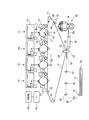
図1は、本実施の形態が適用される画像形成装置を示した概略構成図である。図1に示す画像形成装置は、一般にタンデム型と呼ばれる中間転写方式の画像形成装置であって、電子写真方式により各色成分のトナー像が形成される複数の画像形成ユニット1Y,1M,1C,1K、各画像形成ユニット1Y,1M,1C,1Kにより形成された各色成分トナー像を中間転写ベルト15に順次転写(一次転写)させる一次転写部10、中間転写ベルト15上に転写された重畳トナー画像を記録材である用紙Pに一括転写(二次転写)させる二次転写部20、二次転写された画像(未定着画像)を用紙P上に定着させる定着装置60を備えている。また、各装置(各部)の動作を制御する制御部40、画像形成装置に対する画像形成動作等の指示を受け付け、また、ユーザに対しメッセージ等を表示させるためのユーザインタフェース(UI)41、を有している。
The best mode for carrying out the present invention (hereinafter referred to as an embodiment) will be described below in detail with reference to the accompanying drawings.
FIG. 1 is a schematic configuration diagram illustrating an image forming apparatus to which the exemplary embodiment is applied. The image forming apparatus shown in FIG. 1 is an intermediate transfer type image forming apparatus generally called a tandem type, and a plurality of image forming units 1Y, 1M, 1C, and 1K on which toner images of respective color components are formed by electrophotography. The primary transfer unit 10 that sequentially transfers (primary transfer) the color component toner images formed by the image forming units 1Y, 1M, 1C, and 1K to the intermediate transfer belt 15, and the superimposed toner image transferred onto the intermediate transfer belt 15. Is provided with a secondary transfer unit 20 that collectively transfers (secondary transfer) to a sheet P as a recording material, and a fixing device 60 that fixes the secondary transferred image (unfixed image) onto the sheet P. In addition, it has a control unit 40 that controls the operation of each device (each unit), a user interface (UI) 41 that receives instructions such as an image forming operation to the image forming device, and displays a message or the like to the user. is doing.

本実施の形態において、各画像形成ユニット1Y,1M,1C,1Kは、矢印A方向に回転する感光体ドラム11の周囲に、これらの感光体ドラム11を帯電する帯電器12、感光体ドラム11上に静電潜像を書込むレーザ露光器13(図中露光ビームを符号Bmで示す)、各色成分トナーが収容されて感光体ドラム11上の静電潜像をトナーにより可視像化する現像器14、感光体ドラム11上に形成された各色成分トナー像を一次転写部10にて中間転写ベルト15に転写する一次転写ロール16、感光体ドラム11上の残留トナーが除去されるドラムクリーナ17、などの電子写真用デバイスが順次配設されている。これらの画像形成ユニット1Y,1M,1C,1Kは、中間転写ベルト15の上流側から、イエロー(Y)、マゼンタ(M)、シアン(C)、黒(K)の順に、略直線状に配置されている。   In the present embodiment, each of the image forming units 1Y, 1M, 1C, and 1K has a charger 12 that charges the photosensitive drum 11 around the photosensitive drum 11 that rotates in the direction of arrow A, and the photosensitive drum 11. A laser exposure device 13 for writing an electrostatic latent image thereon (exposure beam is indicated by a symbol Bm in the figure), each color component toner is accommodated, and the electrostatic latent image on the photosensitive drum 11 is visualized with toner. A developing unit 14, a primary transfer roll 16 that transfers each color component toner image formed on the photosensitive drum 11 to the intermediate transfer belt 15 in the primary transfer unit 10, and a drum cleaner that removes residual toner on the photosensitive drum 11. 17 and the like are sequentially arranged. These image forming units 1Y, 1M, 1C, and 1K are arranged in a substantially straight line from the upstream side of the intermediate transfer belt 15 in the order of yellow (Y), magenta (M), cyan (C), and black (K). Has been.

中間転写体である中間転写ベルト15は、ポリイミドあるいはポリアミド等の樹脂にカーボンブラック等の帯電防止剤を適当量含有させたフィルム状の無端ベルトで構成されている。そして、その体積抵抗率は10〜1014Ωcmとなるように形成されており、その厚みは例えば0.1mm程度に構成されている。中間転写ベルト15は、各種ロールによって図1に示す矢印B方向に所定の速度で循環駆動(回動)されている。この各種ロールとして、定速性に優れたモータ(図示せず)により駆動されて中間転写ベルト15を回動させる駆動ロール31、各感光体ドラム11の配列方向に沿って略直線状に延びる中間転写ベルト15を支持する支持ロール32、中間転写ベルト15に対して一定の張力を与えると共に中間転写ベルト15の蛇行を防止する補正ロールとして機能するテンションロール33、二次転写部20に設けられるバックアップロール25、中間転写ベルト15上の残留トナーを掻き取るクリーニング部に設けられるクリーニングバックアップロール34を有している。 The intermediate transfer belt 15 as an intermediate transfer member is constituted by a film-like endless belt in which an appropriate amount of an antistatic agent such as carbon black is contained in a resin such as polyimide or polyamide. And the volume resistivity is formed so that it may become 10 < 6 > -10 < 14 > (omega | ohm) cm, The thickness is comprised by about 0.1 mm, for example. The intermediate transfer belt 15 is circulated and driven (rotated) at a predetermined speed in the direction of arrow B shown in FIG. 1 by various rolls. As these various rolls, a drive roll 31 that is driven by a motor (not shown) having excellent constant speed and rotates the intermediate transfer belt 15, and an intermediate that extends substantially linearly along the arrangement direction of the photosensitive drums 11. A support roll 32 that supports the transfer belt 15, a tension roll 33 that functions as a correction roll that applies a constant tension to the intermediate transfer belt 15 and prevents meandering of the intermediate transfer belt 15, and a backup provided in the secondary transfer unit 20. A cleaning backup roll 34 provided in a cleaning unit for scraping off residual toner on the roll 25 and the intermediate transfer belt 15 is provided.

一次転写部10は、中間転写ベルト15を挟んで感光体ドラム11に対向して配置される一次転写ロール16で構成されている。一次転写ロール16は、シャフトと、シャフトの周囲に固着された弾性層としてのスポンジ層とで構成されている。シャフトは鉄、SUS等の金属で構成された円柱棒である。スポンジ層はカーボンブラック等の導電剤を配合したNBRとSBRとEPDMとのブレンドゴムで形成され、体積抵抗率が107.5〜108.5Ωcmのスポンジ状の円筒ロールである。そして、一次転写ロール16は中間転写ベルト15を挟んで感光体ドラム11に圧接配置され、さらに一次転写ロール16にはトナーの帯電極性(マイナス極性とする。以下同様。)と逆極性の電圧(一次転写バイアス)が印加されるようになっている。これにより、各々の感光体ドラム11上のトナー像が中間転写ベルト15に順次、静電吸引され、中間転写ベルト15上において重畳されたトナー像が形成されるようになっている。 The primary transfer unit 10 includes a primary transfer roll 16 that is disposed to face the photosensitive drum 11 with the intermediate transfer belt 15 interposed therebetween. The primary transfer roll 16 includes a shaft and a sponge layer as an elastic layer fixed around the shaft. The shaft is a cylindrical bar made of metal such as iron or SUS. The sponge layer is a sponge-like cylindrical roll formed of a blend rubber of NBR, SBR and EPDM containing a conductive agent such as carbon black and having a volume resistivity of 10 7.5 to 10 8.5 Ωcm. The primary transfer roll 16 is placed in pressure contact with the photosensitive drum 11 with the intermediate transfer belt 15 in between. Further, the primary transfer roll 16 has a voltage (negative polarity; the same applies hereinafter) with a polarity opposite to that of the toner. (Primary transfer bias) is applied. As a result, the toner images on the respective photosensitive drums 11 are sequentially electrostatically attracted to the intermediate transfer belt 15 so as to form superimposed toner images on the intermediate transfer belt 15.

二次転写部20は、中間転写ベルト15のトナー像担持面側に配置される二次転写ロール22と、バックアップロール25とによって構成される。バックアップロール25は、表面がカーボンを分散したEPDMとNBRとのブレンドゴムのチューブ、内部がEPDMゴムで構成されている。そして、その表面抵抗率が10〜1010Ω/□となるように形成され、硬度は例えば70°(アスカーC)に設定される。このバックアップロール25は、中間転写ベルト15の裏面側に配置されて二次転写ロール22の対向電極をなし、二次転写バイアスが安定的に印加される金属製の給電ロール26が当接配置されている。
一方、二次転写ロール22は、シャフトと、シャフトの周囲に固着された弾性層としてのスポンジ層とで構成されている。シャフトは鉄、SUS等の金属で構成された円柱棒である。スポンジ層はカーボンブラック等の導電剤を配合したNBRとSBRとEPDMとのブレンドゴムで形成され、体積抵抗率が107.5〜108.5Ωcmのスポンジ状の円筒ロールである。そして、二次転写ロール22は中間転写ベルト15を挟んでバックアップロール25に圧接配置され、さらに二次転写ロール22は接地されてバックアップロール25との間に二次転写バイアスが形成され、二次転写部20に搬送される用紙P上にトナー像を二次転写する。
The secondary transfer unit 20 includes a secondary transfer roll 22 disposed on the toner image carrying surface side of the intermediate transfer belt 15 and a backup roll 25. The backup roll 25 is composed of a tube of EPDM and NBR blend rubber with carbon dispersed on the surface, and EPDM rubber on the inside. The surface resistivity is 10 7 to 10 10 Ω / □, and the hardness is set to 70 ° (Asker C), for example. The backup roll 25 is disposed on the back side of the intermediate transfer belt 15 to form a counter electrode of the secondary transfer roll 22, and a metal power supply roll 26 to which a secondary transfer bias is stably applied is disposed in contact with the backup roll 25. ing.
On the other hand, the secondary transfer roll 22 includes a shaft and a sponge layer as an elastic layer fixed around the shaft. The shaft is a cylindrical bar made of metal such as iron or SUS. The sponge layer is a sponge-like cylindrical roll formed of a blend rubber of NBR, SBR and EPDM containing a conductive agent such as carbon black and having a volume resistivity of 10 7.5 to 10 8.5 Ωcm. The secondary transfer roll 22 is disposed in pressure contact with the backup roll 25 with the intermediate transfer belt 15 interposed therebetween. Further, the secondary transfer roll 22 is grounded, and a secondary transfer bias is formed between the secondary transfer roll 22 and the backup roll 25. The toner image is secondarily transferred onto the paper P conveyed to the transfer unit 20.

また、中間転写ベルト15の二次転写部20の下流側には、二次転写後の中間転写ベルト15上の残留トナーや紙粉を除去し、中間転写ベルト15の表面をクリーニングするベルトクリーナ35が接離自在に設けられている。一方、イエローの画像形成ユニット1Yの上流側には、各画像形成ユニット1Y,1M,1C,1Kにおける画像形成タイミングをとるための基準となる基準信号を発生する基準センサ(ホームポジションセンサ)42が配設されている。また、黒の画像形成ユニット1Kの下流側には、画質調整を行うための画像濃度センサ43が配設されている。この基準センサ42は、中間転写ベルト15の裏側に設けられた所定のマークを認識して基準信号を発生しており、この基準信号の認識に基づく制御部40からの指示により、各画像形成ユニット1Y,1M,1C,1Kは画像形成を開始するように構成されている。   Further, on the downstream side of the secondary transfer portion 20 of the intermediate transfer belt 15, a belt cleaner 35 that removes residual toner and paper dust on the intermediate transfer belt 15 after the secondary transfer and cleans the surface of the intermediate transfer belt 15. Is provided so as to be freely contactable. On the other hand, on the upstream side of the yellow image forming unit 1Y, a reference sensor (home position sensor) 42 that generates a reference signal serving as a reference for taking image forming timings in the image forming units 1Y, 1M, 1C, and 1K. It is arranged. Further, an image density sensor 43 for adjusting image quality is disposed on the downstream side of the black image forming unit 1K. The reference sensor 42 recognizes a predetermined mark provided on the back side of the intermediate transfer belt 15 and generates a reference signal. Each image forming unit is instructed by an instruction from the control unit 40 based on the recognition of the reference signal. 1Y, 1M, 1C, and 1K are configured to start image formation.

さらに、本実施の形態の画像形成装置では、用紙搬送系として、用紙Pを収容する用紙トレイ50、この用紙トレイ50に集積された用紙Pを所定のタイミングで取り出して搬送するピックアップロール51、ピックアップロール51により繰り出された用紙Pを搬送する搬送ロール52、搬送ロール52により搬送された用紙Pを二次転写部20へと送り込む搬送シュート53、二次転写ロール22により二次転写された後に搬送される用紙Pを定着装置60へと搬送する搬送ベルト55、用紙Pを定着装置60に導く定着入口ガイド56を備えている。   Further, in the image forming apparatus according to the present embodiment, as a paper transport system, a paper tray 50 that stores paper P, a pickup roll 51 that picks up and transports the paper P accumulated in the paper tray 50 at a predetermined timing, and a pickup A transport roll 52 that transports the paper P fed by the roll 51, a transport chute 53 that feeds the paper P transported by the transport roll 52 to the secondary transfer unit 20, and transported after being secondarily transferred by the secondary transfer roll 22. A conveyance belt 55 that conveys the paper P to be fixed to the fixing device 60 and a fixing inlet guide 56 that guides the paper P to the fixing device 60 are provided.

次に、本実施の形態に係る画像形成装置の基本的な作像プロセスについて説明する。図1に示すような画像形成装置では、図示しない画像読取装置(IIT)や図示しないパーソナルコンピュータ(PC)等から出力される画像データは、図示しない画像処理装置(IPS)により所定の画像処理が施された後、画像形成ユニット1Y,1M,1C,1Kによって作像作業が実行される。IPSでは、入力された反射率データに対して、シェーディング補正、位置ズレ補正、明度/色空間変換、ガンマ補正、枠消しや色編集、移動編集等の各種画像編集等の所定の画像処理が施される。画像処理が施された画像データは、Y、M、C、Kの4色の色材階調データに変換され、レーザ露光器13に出力される。   Next, a basic image forming process of the image forming apparatus according to the present embodiment will be described. In an image forming apparatus as shown in FIG. 1, image data output from an image reading device (IIT) not shown or a personal computer (PC) not shown is subjected to predetermined image processing by an image processing device (IPS) not shown. After being applied, the image forming operation is executed by the image forming units 1Y, 1M, 1C, and 1K. In IPS, the input reflectance data is subjected to predetermined image processing such as shading correction, position shift correction, brightness / color space conversion, gamma correction, frame deletion, color editing, moving editing, and other various image editing. Is done. The image data that has undergone image processing is converted into color material gradation data of four colors, Y, M, C, and K, and is output to the laser exposure unit 13.

レーザ露光器13では、入力された色材階調データに応じて、例えば半導体レーザから出射された露光ビームBmを画像形成ユニット1Y,1M,1C,1Kの各々の感光体ドラム11に照射している。画像形成ユニット1Y,1M,1C,1Kの各感光体ドラム11では、帯電器12によって表面が帯電された後、このレーザ露光器13によって表面が走査露光され、静電潜像が形成される。形成された静電潜像は、各々の画像形成ユニット1Y,1M,1C,1Kによって、Y、M、C、Kの各色のトナー像として現像される。   The laser exposure unit 13 irradiates the photosensitive drums 11 of the image forming units 1Y, 1M, 1C, and 1K, for example, with an exposure beam Bm emitted from a semiconductor laser in accordance with the input color material gradation data. Yes. In each of the photosensitive drums 11 of the image forming units 1Y, 1M, 1C, and 1K, the surface is charged by the charger 12, and then the surface is scanned and exposed by the laser exposure unit 13 to form an electrostatic latent image. The formed electrostatic latent images are developed as toner images of respective colors Y, M, C, and K by the respective image forming units 1Y, 1M, 1C, and 1K.

画像形成ユニット1Y,1M,1C,1Kの感光体ドラム11上に形成されたトナー像は、各感光体ドラム11と中間転写ベルト15とが当接する一次転写部10において、中間転写ベルト15上に転写される。より具体的には、一次転写部10において、一次転写ロール16により中間転写ベルト15の基材に対しトナーの帯電極性(マイナス極性)と逆極性の電圧(一次転写バイアス)が付加され、トナー像を中間転写ベルト15の表面に順次重ね合わせて一次転写が行われる。   The toner images formed on the photosensitive drums 11 of the image forming units 1Y, 1M, 1C, and 1K are transferred onto the intermediate transfer belt 15 in the primary transfer unit 10 where the photosensitive drums 11 and the intermediate transfer belt 15 come into contact with each other. Transcribed. More specifically, in the primary transfer unit 10, a voltage (primary transfer bias) having a polarity opposite to the charging polarity (minus polarity) of toner is applied to the base material of the intermediate transfer belt 15 by the primary transfer roll 16, and the toner image. Are sequentially superimposed on the surface of the intermediate transfer belt 15 to perform primary transfer.

トナー像が中間転写ベルト15の表面に順次一次転写された後、中間転写ベルト15は移動してトナー像が二次転写部20に搬送される。トナー像が二次転写部20に搬送されると、用紙搬送系では、トナー像が二次転写部20に搬送されるタイミングに合わせてピックアップロール51が回転し、用紙トレイ50から所定サイズの用紙Pが供給される。ピックアップロール51により供給された用紙Pは、搬送ロール52により搬送され、搬送シュート53を経て二次転写部20に到達する。この二次転写部20に到達する前に、用紙Pは一旦停止され、トナー像が担持された中間転写ベルト15の移動タイミングに合わせてレジストロール(図示せず)が回転することで、用紙Pの位置とトナー像の位置との位置合わせがなされる。   After the toner images are sequentially primary transferred onto the surface of the intermediate transfer belt 15, the intermediate transfer belt 15 moves and the toner image is conveyed to the secondary transfer unit 20. When the toner image is transported to the secondary transfer unit 20, in the paper transport system, the pick-up roll 51 rotates in accordance with the timing at which the toner image is transported to the secondary transfer unit 20, and the paper of a predetermined size is transferred from the paper tray 50. P is supplied. The paper P supplied by the pickup roll 51 is transported by the transport roll 52 and reaches the secondary transfer unit 20 via the transport chute 53. Before reaching the secondary transfer unit 20, the paper P is temporarily stopped, and a registration roll (not shown) rotates in accordance with the movement timing of the intermediate transfer belt 15 on which the toner image is carried. And the position of the toner image are aligned.

二次転写部20では、中間転写ベルト15を介して、二次転写ロール22がバックアップロール25に押圧される。このとき、タイミングを合わせて搬送された用紙Pは、中間転写ベルト15と二次転写ロール22との間に挟み込まれる。その際に、給電ロール26からトナーの帯電極性(マイナス極性)と同極性の電圧(二次転写バイアス)が印加されると、二次転写ロール22とバックアップロール25との間に転写電界が形成される。そして、中間転写ベルト15上に担持された未定着トナー像は、二次転写ロール22とバックアップロール25とによって押圧される二次転写部20において、用紙P上に一括して静電転写される。   In the secondary transfer unit 20, the secondary transfer roll 22 is pressed against the backup roll 25 via the intermediate transfer belt 15. At this time, the sheet P conveyed at the same timing is sandwiched between the intermediate transfer belt 15 and the secondary transfer roll 22. At this time, when a voltage (secondary transfer bias) having the same polarity as the toner charging polarity (negative polarity) is applied from the power supply roll 26, a transfer electric field is formed between the secondary transfer roll 22 and the backup roll 25. Is done. The unfixed toner image carried on the intermediate transfer belt 15 is collectively electrostatically transferred onto the paper P in the secondary transfer unit 20 pressed by the secondary transfer roll 22 and the backup roll 25. .

その後、トナー像が静電転写された用紙Pは、二次転写ロール22によって中間転写ベルト15から剥離された状態でそのまま搬送され、二次転写ロール22の用紙搬送方向下流側に設けられた搬送ベルト55へと搬送される。搬送ベルト55では、定着装置60における最適な搬送速度に合わせて、用紙Pを定着装置60まで搬送する。定着装置60に搬送された用紙P上の未定着トナー像は、定着装置60によって熱および圧力で定着処理を受けることで用紙P上に定着される。そして定着画像が形成された用紙Pは、画像形成装置の排出部に設けられた排紙載置部に搬送される。
一方、用紙Pへの転写が終了した後、中間転写ベルト15上に残った残留トナーは、中間転写ベルト15の回動に伴ってクリーニング部まで搬送され、クリーニングバックアップロール34およびベルトクリーナ35によって中間転写ベルト15上から除去される。
Thereafter, the sheet P on which the toner image has been electrostatically transferred is transported as it is while being peeled off from the intermediate transfer belt 15 by the secondary transfer roll 22, and transported downstream of the secondary transfer roll 22 in the sheet transport direction. It is conveyed to the belt 55. The conveyance belt 55 conveys the paper P to the fixing device 60 in accordance with the optimum conveyance speed in the fixing device 60. The unfixed toner image on the paper P conveyed to the fixing device 60 is fixed on the paper P by being subjected to a fixing process by heat and pressure by the fixing device 60. Then, the paper P on which the fixed image is formed is conveyed to a paper discharge placement unit provided in a discharge unit of the image forming apparatus.
On the other hand, after the transfer to the paper P is completed, the residual toner remaining on the intermediate transfer belt 15 is conveyed to the cleaning unit as the intermediate transfer belt 15 rotates, and is intermediately transferred by the cleaning backup roll 34 and the belt cleaner 35. It is removed from the transfer belt 15.

次に、本実施の形態の画像形成装置に用いられる定着装置60について説明する。
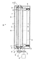
図2は本実施の形態の定着装置60の構成を示す概略正面図であり、図3は図2におけるX1−X1断面図である。図2および図3に示すように、本実施の形態の定着装置60は、無端状の周面を有する定着ベルト61、定着ベルト61の外周面に圧接して配設され、定着ベルト61の回動に従動して回転する加圧ロール62、定着ベルト61の内側にて定着ベルト61を介して加圧ロール62に圧接配置される押圧パッド63、押圧パッド63等を支持するパッド支持部材64、定着ベルト61の外周面形状に倣って形成されるとともに定着ベルト61とは所定の間隙を持って配設され、定着ベルト61を長手方向に亘って電磁誘導加熱する電磁誘導加熱部材65、定着ベルト61の両端部に配設され、定着ベルト61の両端部の断面形状を円形に維持しつつ定着ベルト61を周方向に回転駆動するエンドキャップ部材66、定着ベルト61の内側にて定着ベルト61の内周面に沿って配設され、電磁誘導加熱部材65による定着ベルト61への加熱効率を高めるフェライト部材67、定着ベルト61のライフを判断するのに用いられるセンサコイル71により主要部が構成されている。なお、図2においては、後述する温度均一化ロール72の記載を省略している。また、定着後の用紙Pを定着ベルト61から完全に分離するための補助手段として、定着ベルト61の定着ニップ部Nの下流側に、剥離補助部材75を配設することも可能である。
Next, the fixing device 60 used in the image forming apparatus of the present embodiment will be described.
FIG. 2 is a schematic front view showing the configuration of the fixing device 60 of the present embodiment, and FIG. 3 is a cross-sectional view taken along line X1-X1 in FIG. As shown in FIGS. 2 and 3, the fixing device 60 of the present embodiment is disposed in contact with the fixing belt 61 having an endless peripheral surface and the outer peripheral surface of the fixing belt 61. A pressure roll 62 that rotates following movement, a pressure pad 63 disposed in pressure contact with the pressure roll 62 via the fixing belt 61 inside the fixing belt 61, a pad support member 64 that supports the pressure pad 63, and the like. An electromagnetic induction heating member 65 that is formed to follow the shape of the outer peripheral surface of the fixing belt 61 and that is disposed with a predetermined gap from the fixing belt 61 and electromagnetically heats the fixing belt 61 in the longitudinal direction. An end cap member 66 that is disposed at both ends of the fixing belt 61 and rotationally drives the fixing belt 61 in the circumferential direction while maintaining a circular cross-sectional shape at both ends of the fixing belt 61, and is fixed inside the fixing belt 61. A main part is provided by a ferrite member 67 arranged along the inner peripheral surface of the belt 61 to increase the heating efficiency of the fixing belt 61 by the electromagnetic induction heating member 65, and a sensor coil 71 used to determine the life of the fixing belt 61. Is configured. In FIG. 2, description of a temperature equalizing roll 72 described later is omitted. Further, as an auxiliary means for completely separating the fixed paper P from the fixing belt 61, a peeling auxiliary member 75 can be disposed on the downstream side of the fixing nip portion N of the fixing belt 61.

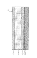
ベルト部材の一つとしての定着ベルト61は、図4に示すように、内周面側から順に、耐熱性の高いシート状部材からなる基層61aと、導電性層(金属層)61bと、保護層61cと、弾性層61dと、外周面となる表面離型層61eとが積層されて構成されている。また、各層の間には接着のためのプライマー層や導電性層に発生するクラックを防止するための保護層等が設けられる場合がある。   As shown in FIG. 4, the fixing belt 61 as one of the belt members includes, in order from the inner peripheral surface side, a base layer 61a made of a sheet-like member having high heat resistance, a conductive layer (metal layer) 61b, and a protective layer. A layer 61c, an elastic layer 61d, and a surface release layer 61e serving as an outer peripheral surface are laminated. Further, a primer layer for adhesion or a protective layer for preventing cracks generated in the conductive layer may be provided between the layers.

基層61aとしては、フッ素樹脂、ポリイミド樹脂、ポリアミド樹脂、ポリアミドイミド樹脂、PEEK樹脂、PES樹脂、PPS樹脂、PFA樹脂、PTFE樹脂、FEP樹脂等のフレキシブルで機械的強度に優れ、耐熱性を有する材料が好適に用いられる。厚さは、10〜150μm、好ましくは厚さ30〜100μmが適している。厚さが10μmより小さい場合には定着ベルト61としての強度が得られず、厚さが150μmより大きい場合には、フレキシブル性が損なわれ、また熱容量が大きくなって温度立ち上がり時間が長くなるからである。本実施の形態では、厚さ60μmのポリイミド樹脂からなるシート状部材を使用している。   As the base layer 61a, a material having flexibility, excellent mechanical strength and heat resistance, such as fluororesin, polyimide resin, polyamide resin, polyamideimide resin, PEEK resin, PES resin, PPS resin, PFA resin, PTFE resin, FEP resin, etc. Are preferably used. The thickness is 10 to 150 μm, preferably 30 to 100 μm. If the thickness is smaller than 10 μm, the strength as the fixing belt 61 cannot be obtained. If the thickness is larger than 150 μm, the flexibility is impaired, and the heat capacity increases and the temperature rise time becomes longer. is there. In the present embodiment, a sheet-like member made of a polyimide resin having a thickness of 60 μm is used.

導電性層61bは、電磁誘導加熱部材65が誘起する磁界により誘導発熱する層(発熱層)であり、鉄、コバルト、ニッケル、銅、アルミニウム、クロム等の金属層を1〜80μm程度の厚さで形成したものが用いられる。また、導電性層61bの材質および厚さは、電磁誘導による渦電流によって充分な発熱が得られる固有抵抗値を実現するように適宜選択される。ただし、定着ベルト61からの用紙Pの剥離性能を良好にするためには、定着ニップ出口部において、定着ベルト61に大きな曲率を与えて剥離させることが好ましく、そのため定着ベルト61にはフレキシビリティが求められる。例えば、鉄やニッケルなどは40〜50μm程度の厚さで発熱効率が良好であるが、定着ベルト61の剛性としては高くなってしまいフレキシビリティが損なわれてしまう。そこで、本実施の形態では、厚さ10μm程度の銅を使用しフレキシビリティを有するベルトにしている。   The conductive layer 61b is a layer (heat generation layer) that generates heat by a magnetic field induced by the electromagnetic induction heating member 65, and a metal layer such as iron, cobalt, nickel, copper, aluminum, or chromium has a thickness of about 1 to 80 μm. What was formed in is used. The material and thickness of the conductive layer 61b are appropriately selected so as to realize a specific resistance value that can generate sufficient heat by eddy current due to electromagnetic induction. However, in order to improve the peeling performance of the paper P from the fixing belt 61, it is preferable to peel the fixing belt 61 with a large curvature at the exit of the fixing nip. Therefore, the fixing belt 61 has flexibility. Desired. For example, iron or nickel has a thickness of about 40 to 50 μm and good heat generation efficiency, but the rigidity of the fixing belt 61 is increased and flexibility is impaired. Therefore, in this embodiment, copper having a thickness of about 10 μm is used to form a flexible belt.

保護層61cは、定着ベルト61全体が曲げられた時に、その曲げの中立線上に導電性層61bが来るように調整するための層であり、保護層61cとして使用する材料の剛性によりその厚さが決定される。そのため材料としては耐熱性を有しており、導電性層61bと弾性層61dとの接着力が得られるものであれば良く、例えばポリイミドなどの樹脂やニッケルなどの金属が挙げられる。本実施例では、基層61a、導電性層61b、弾性層61d、表面離型層61eのそれぞれの剛性と厚さを考慮して、保護層61cとしては厚さが40μmのポリイミドを用いている。
弾性層61dは、厚さが10〜500μm、好ましくは50〜300μmであって、耐熱性、熱伝導性に優れたシリコーンゴム、フッ素ゴム、フルオロシリコーンゴム等が用いられる。本実施の形態では、ゴム硬度15°(JIS−A:JIS−K A型試験機)、厚さ200μmのシリコーンゴムを使用している。
The protective layer 61c is a layer for adjusting the conductive layer 61b so that the conductive layer 61b comes on the bending neutral line when the entire fixing belt 61 is bent, and the thickness thereof depends on the rigidity of the material used as the protective layer 61c. Is determined. Therefore, any material may be used as long as it has heat resistance and can provide an adhesive force between the conductive layer 61b and the elastic layer 61d. Examples thereof include resins such as polyimide and metals such as nickel. In this embodiment, considering the rigidity and thickness of the base layer 61a, the conductive layer 61b, the elastic layer 61d, and the surface release layer 61e, polyimide having a thickness of 40 μm is used as the protective layer 61c.
The elastic layer 61d has a thickness of 10 to 500 [mu] m, preferably 50 to 300 [mu] m, and silicone rubber, fluorine rubber, fluorosilicone rubber, etc. excellent in heat resistance and thermal conductivity are used. In the present embodiment, silicone rubber having a rubber hardness of 15 ° (JIS-A: JIS-KA type tester) and a thickness of 200 μm is used.

ところで、カラー画像を印刷する場合、特に写真画像等の印刷時には、用紙P上で大きな面積領域に亘ってベタ画像が形成されることが多い。そのため、用紙Pやトナー像の凹凸に定着ベルト61の表面(表面離型層61e)が追従できない場合には、トナー像に加熱ムラが発生して、伝熱量が多い部分と少ない部分とで定着画像に光沢ムラが発生する。すなわち、伝熱量が多い部分は光沢度が高く、伝熱量が少ない部分では光沢度が低くなる。このような現象は、弾性層61dの厚さが10μmより小さい場合に生じ易い。そこで、弾性層61dの厚さは、10μm以上、より好ましくは50μm以上に設定するのが好ましい。一方、弾性層61dが500μmより大きい場合には、弾性層61dの熱抵抗が大きくなり、定着装置60のクイックスタート性能が低下する。そこで、弾性層61dの厚さは、500μm以下、より好ましくは300μm以下に設定するのが好ましい。
また、弾性層61dのゴム硬度としては、高すぎると用紙Pやトナー像の凹凸に追従しきれず定着画像に光沢ムラが発生し易い。そこで、弾性層61dのゴム硬度としては50゜(JIS−A:JIS−K A型試験機)以下、より好ましくは35゜以下が適している。
さらに、弾性層61dの熱伝導率λに関しては、λ=6×10⁻⁴〜2×10⁻³[cal/cm・sec・deg ]が適している。熱伝導率λが6×10⁻⁴[cal/cm・sec・deg ]よりも小さい場合には熱抵抗が大きく、定着ベルト61の表層(表面離型層61e)における温度上昇が遅くなる。一方、熱伝導率λが2×10⁻³[cal/cm・sec・deg ]よりも大きい場合には、硬度が過度に高くなったり、圧縮永久歪みが悪化したりする。そのため、熱伝導率λは6×10⁻⁴〜2×10⁻³[cal/cm・sec・deg ]、より好ましくは8×10⁻⁴〜1.5×10⁻³[cal/cm・sec・deg ]に設定するのが好ましい。
By the way, when printing a color image, especially when printing a photographic image or the like, a solid image is often formed over a large area on the paper P. For this reason, when the surface of the fixing belt 61 (surface release layer 61e) cannot follow the unevenness of the paper P or toner image, heating unevenness occurs in the toner image, and fixing is performed between a portion with a large amount of heat transfer and a portion with a small amount of heat transfer. Uneven gloss occurs in the image. That is, the glossiness is high in the portion where the heat transfer amount is large, and the glossiness is low in the portion where the heat transfer amount is small. Such a phenomenon is likely to occur when the thickness of the elastic layer 61d is smaller than 10 μm. Therefore, the thickness of the elastic layer 61d is preferably set to 10 μm or more, more preferably 50 μm or more. On the other hand, when the elastic layer 61d is larger than 500 μm, the thermal resistance of the elastic layer 61d increases, and the quick start performance of the fixing device 60 decreases. Therefore, the thickness of the elastic layer 61d is preferably set to 500 μm or less, more preferably 300 μm or less.
Further, if the rubber hardness of the elastic layer 61d is too high, the unevenness of the paper P or the toner image cannot be followed and gloss unevenness tends to occur in the fixed image. Accordingly, the rubber hardness of the elastic layer 61d is not more than 50 ° (JIS-A: JIS-KA type tester), more preferably not more than 35 °.
Furthermore, regarding the thermal conductivity λ of the elastic layer 61d, λ = 6 × 10 −4 to 2 × 10 −3 [cal / cm · sec · deg] is suitable. When the thermal conductivity λ is smaller than 6 × 10 −4 [cal / cm · sec · deg], the thermal resistance is large, and the temperature rise in the surface layer (surface release layer 61e) of the fixing belt 61 is delayed. On the other hand, when the thermal conductivity λ is larger than 2 × 10 −3 [cal / cm · sec · deg], the hardness becomes excessively high or the compression set is deteriorated. Therefore, the thermal conductivity λ is 6 × 10 −4 to 2 × 10 −3 [cal / cm · sec · deg], more preferably 8 × 10 −4 to 1.5 × 10 −3 [cal / cm · sec]. It is preferable to set to deg].

また、表面離型層61eは、用紙P上に転写された未定着トナー像と直接的に接触する層であるため、離型性および耐熱性に優れた材料を使用する必要がある。したがって、表面離型層61eを構成する材料としては、例えばテトラフルオロエチレンパーフルオロアルキルビニルエーテル重合体(PFA)、ポリテトラフルオロエチレン(PTFE)、フッ素樹脂、シリコーン樹脂、フルオロシリコーンゴム、フッ素ゴム、シリコーンゴム等が好適に用いられる。
また、表面離型層61eの厚さは、5〜50μmが好ましい。表面離型層61eの厚さが5μmよりも小さい場合には、塗膜時に塗りムラが生じて離型性の悪い領域が形成されたり、耐久性が不足したりするといった問題が発生するからである。また、表面離型層61eが50μmを超える場合には、熱伝導が悪化するという問題が発生し、特に樹脂系の材質で形成された表面離型層61eでは硬度が高くなりすぎ、弾性層61dが有する機能を低下させるからである。なお、本実施の形態では、厚さ30μmのPFAを使用している。
Further, since the surface release layer 61e is a layer that is in direct contact with the unfixed toner image transferred onto the paper P, it is necessary to use a material having excellent release properties and heat resistance. Accordingly, examples of the material constituting the surface release layer 61e include tetrafluoroethylene perfluoroalkyl vinyl ether polymer (PFA), polytetrafluoroethylene (PTFE), fluororesin, silicone resin, fluorosilicone rubber, fluororubber, and silicone. Rubber or the like is preferably used.
The thickness of the surface release layer 61e is preferably 5 to 50 μm. When the thickness of the surface release layer 61e is smaller than 5 μm, there is a problem that uneven coating occurs when the coating film is formed, an area having poor release properties is formed, or durability is insufficient. is there. Further, when the surface release layer 61e exceeds 50 μm, there arises a problem that heat conduction is deteriorated. In particular, the surface release layer 61e formed of a resin-based material has too high hardness, and the elastic layer 61d. It is because the function which has is reduced. In this embodiment, PFA with a thickness of 30 μm is used.

次に、加圧部材あるいはニップ形成部材の一つとしての加圧ロール62は、図3に示したように、芯材(コア)としての金属製の円筒状部材62aと、円筒状部材62aの表面にシリコーンゴム、発泡シリコーンゴム、フッ素ゴム、フッ素樹脂等の耐熱性を有する弾性層62bと、最外表面の表面離型層62cとで構成されている。そして、図2に示したように、加圧ロール62は、定着ベルト61の回転軸と平行に配設されるとともに、両端部がバネ部材68によって定着ベルト61側に付勢されて支持されている。本実施の形態では、直径が28mmの加圧ロール62を使用し、加圧ロール62は、定着動作時には、定着ベルト61を介して総荷重294N(30kgf)で押圧パッド63に付勢されている。そして、このような構成により、加圧ロール62は定着ベルト61の回動に従動して回転する。また、加圧ロール62には、例えばヒートパイプ等によって構成される温度均一化ロール72が回転可能に圧接配置されている。この温度均一化ロール72は、加圧ロール62に接触することで、温度が高い部位からは熱を奪い、また、温度が低い部位には熱を供給することで、加圧ロール62の軸方向の温度分布を均している。   Next, as shown in FIG. 3, the pressure roll 62 as one of the pressure member or the nip forming member includes a metal cylindrical member 62a as a core material (core), and a cylindrical member 62a. The surface is composed of an elastic layer 62b having heat resistance such as silicone rubber, foamed silicone rubber, fluororubber, and fluororesin, and a surface release layer 62c on the outermost surface. As shown in FIG. 2, the pressure roll 62 is disposed in parallel with the rotation shaft of the fixing belt 61, and both ends are urged and supported by the spring member 68 toward the fixing belt 61. Yes. In this embodiment, a pressure roll 62 having a diameter of 28 mm is used, and the pressure roll 62 is urged to the pressing pad 63 by a total load 294N (30 kgf) via the fixing belt 61 during the fixing operation. . With such a configuration, the pressure roll 62 rotates following the rotation of the fixing belt 61. In addition, a temperature equalizing roll 72 configured by, for example, a heat pipe or the like is press-contacted to the pressure roll 62 so as to be rotatable. The temperature equalizing roll 72 is brought into contact with the pressure roll 62 so that heat is taken away from a part having a high temperature, and heat is supplied to a part having a low temperature so that the axial direction of the pressure roll 62 is reached. The temperature distribution is leveled.

押圧部材の一つとしての押圧パッド63は、その主たる部分はシリコーンゴムやフッ素ゴム等の弾性材料で形成されており、SUSや鉄などからなるパッド支持板63aと一体で成型されている。押圧パッド63は、定着ベルト61の幅方向において、用紙Pが通過する領域(通紙域)よりもやや広い領域に亘って配設され、この押圧パッド63の長手方向の略全長に亘って加圧ロール62が押圧されるように構成されている。   The main part of the pressing pad 63 as one of the pressing members is formed of an elastic material such as silicone rubber or fluorine rubber, and is molded integrally with a pad support plate 63a made of SUS, iron or the like. The pressing pad 63 is arranged over a region slightly wider than the region (sheet passing region) through which the paper P passes in the width direction of the fixing belt 61, and the pressing pad 63 is applied over substantially the entire length of the pressing pad 63 in the longitudinal direction. The pressure roll 62 is configured to be pressed.

図5は、押圧パッド63を説明するための図であり、図5(a)は押圧パッド63の斜視図を、図5(b)は用紙Pが通過する通紙域A1における押圧パッド63の断面図を、図5(c)は用紙Pが通過しない非通紙域A2における押圧パッド63の断面図を、それぞれ示している。
通紙域A1における押圧パッド63の断面形状は、図5(b)に示すように相対する加圧ロール62と同じ方向でかつ概略等しい半径の円弧であり、定着ニップ入口側に相当する部分よりも出口側に相当する部分の弾性層厚さが厚くなっている。一方、非通紙域A2における押圧パッド63の断面形状は、図5(c)に示すように定着ベルト61の形状に倣う円弧形状を有している。
5A and 5B are diagrams for explaining the pressing pad 63. FIG. 5A is a perspective view of the pressing pad 63, and FIG. 5B is a diagram of the pressing pad 63 in the sheet passing area A1 through which the paper P passes. FIG. 5C shows a cross-sectional view of the pressing pad 63 in the non-sheet passing area A2 where the paper P does not pass.
As shown in FIG. 5B, the cross-sectional shape of the pressing pad 63 in the sheet passing area A1 is an arc having the same direction as the opposing pressure roll 62 and substantially the same radius, and from the portion corresponding to the fixing nip inlet side. Also, the elastic layer thickness of the portion corresponding to the outlet side is increased. On the other hand, the cross-sectional shape of the pressing pad 63 in the non-sheet passing area A2 has an arc shape that follows the shape of the fixing belt 61 as shown in FIG.

この押圧パッド63は、定着ニップ形成時に、定着ベルト61を定着ニップ出口部において、所定の曲率となるように変形させる働きを有しており、用紙Pの良好な剥離性能を得るためには、その形状や硬度が重要である。したがって、押圧パッド63は経時でも形状や硬度が変化しないことが好ましく、材料としては、耐熱劣化特性に優れたものを選択するのが好ましい。この定着装置60では、液状シリコーンゴムで成型したゴム硬度30°(JIS−A)のパッドを使用している。またその形状はφ28mmである加圧ロール62の円弧と概略等しいR15の円弧を有し、定着ニップ入口側の厚さよりも出口側の厚さが約2.5mm高い形状となっている。   The pressing pad 63 has a function of deforming the fixing belt 61 so as to have a predetermined curvature at the fixing nip exit portion at the time of forming the fixing nip. Its shape and hardness are important. Therefore, it is preferable that the shape and hardness of the pressing pad 63 does not change over time, and it is preferable to select a material having excellent heat resistance deterioration characteristics as the material. The fixing device 60 uses a pad with a rubber hardness of 30 ° (JIS-A) molded from liquid silicone rubber. Further, the shape thereof has an arc of R15 that is substantially equal to the arc of the pressure roll 62 having a diameter of 28 mm, and the thickness on the exit side is approximately 2.5 mm higher than the thickness on the entrance side of the fixing nip.

さらに後述するように、定着ベルト61の両端部には定着ベルト61内部に嵌合するギヤ付きのエンドキャップ部材66が挿入されることで、定着ベルト61を円形に保つ構成となっている。このため、押圧パッド63は、軸方向の両端部では定着ベルト61の内径にほぼ等しい形状となっており、定着ベルト61の通紙域A1における用紙Pの剥離に必要な断面形状(図3参照)から非通紙域A2の両端部における円形の断面形状(後述する図7参照)へと移行する変形を滑らかにするように構成されている。具体的には、定着ベルト61の導電性層61bに装置使用初期の段階からクラックが発生したり、ベルトが破損したりするのを防止するために、押圧パッド63の形状は図5(b)に示すように、軸方向で通紙域A1と非通紙域A2との境界近傍に置いて断面が滑らかに変化するような形状となっている。   Further, as will be described later, an end cap member 66 with a gear that fits inside the fixing belt 61 is inserted into both ends of the fixing belt 61 so that the fixing belt 61 is kept circular. For this reason, the pressing pad 63 has a shape substantially equal to the inner diameter of the fixing belt 61 at both ends in the axial direction, and a cross-sectional shape necessary for peeling the paper P in the paper passing area A1 of the fixing belt 61 (see FIG. 3). ) To a circular cross-sectional shape (see FIG. 7 described later) at both ends of the non-sheet passing area A2. Specifically, in order to prevent the conductive layer 61b of the fixing belt 61 from being cracked from the initial stage of use of the apparatus or from being damaged, the shape of the pressing pad 63 is shown in FIG. As shown in the figure, the cross section is smoothly changed in the axial direction in the vicinity of the boundary between the sheet passing area A1 and the non-sheet passing area A2.

また、押圧パッド63と定着ベルト61との間には、定着ニップ部Nにおける押圧パッド63と定着ベルト61との摺動性を向上するため、摺動性に優れ、耐摩耗性が高いポリイミドフィルムやフッ素樹脂を含浸させたガラス繊維シート等からなる図示しない摺動シートが配設されている。さらに、定着ベルト61の内周面には潤滑剤が塗布されている。潤滑剤としては、アミノ変性シリコーンオイルやジメチルシリコーンオイル等が用いられる。これらにより、定着ベルト61と押圧パッド63との間の摩擦抵抗が小さくなり、定着ベルト61を円滑に回動させることを可能としている。   Further, a polyimide film having excellent slidability and high wear resistance is provided between the pressing pad 63 and the fixing belt 61 in order to improve the sliding property between the pressing pad 63 and the fixing belt 61 in the fixing nip portion N. Further, a sliding sheet (not shown) made of a glass fiber sheet impregnated with fluorine resin is disposed. Further, a lubricant is applied to the inner peripheral surface of the fixing belt 61. As the lubricant, amino-modified silicone oil, dimethyl silicone oil, or the like is used. As a result, the frictional resistance between the fixing belt 61 and the pressing pad 63 is reduced, and the fixing belt 61 can be smoothly rotated.

パッド支持部材64は、定着ベルト61の幅方向に軸線を有する棒状部材であり、両端部に軸部64aが突き出した形状で構成されている。そして、この軸部64aが定着装置60のフレーム69に固定されることで、パッド支持部材64がフレーム69に支持されている。また、定着ベルト61の両端部では、軸部64aの軸線回りにベアリングを介して後段で説明するエンドキャップ部材66が配設され、パッド支持部材64の軸部64aは、エンドキャップ部材66が装着された定着ベルト61を回転可能に支持している。   The pad support member 64 is a rod-shaped member having an axis in the width direction of the fixing belt 61, and is configured to have a shape in which a shaft portion 64a protrudes from both ends. The shaft 64 a is fixed to the frame 69 of the fixing device 60, so that the pad support member 64 is supported by the frame 69. Further, at both ends of the fixing belt 61, an end cap member 66, which will be described later, is disposed around a shaft line of the shaft portion 64a via a bearing, and the end cap member 66 is mounted on the shaft portion 64a of the pad support member 64. The fixed fixing belt 61 is rotatably supported.

さらに、パッド支持部材64の加圧ロール62と対向する部分には押圧パッド63が取り付けられており、定着ベルト61を介して加圧ロール62から押圧パッド63に作用する押圧力をパッド支持部材64によって負担している。そのため、パッド支持部材64を構成する材質としては、加圧ロール62から押圧力を受けた際の撓み量が所定のレベル以下、好ましくは1mm以下となる程度の剛性を有するものが用いられる。そのため、後述する電磁誘導加熱部材65による磁束の影響によって加熱されにくい必要をも考慮して、例えば、ガラス繊維入りPPS、フェノール、ポリイミド、液晶ポリマー等の耐熱性樹脂、耐熱ガラス、固有抵抗が小さく誘導加熱の影響を受けにくいアルミニウム等の金属が用いられる。本実施の形態では、パッド支持部材64は、本体部分の断面形状が加圧ロール62からの押圧力方向に長軸を有する長方形で形成され、軸部64aの断面形状が略円形に形成されたアルミニウムで構成されている。   Further, a pressing pad 63 is attached to a portion of the pad support member 64 facing the pressure roll 62, and the pressing force acting on the pressing pad 63 from the pressure roll 62 via the fixing belt 61 is applied to the pad support member 64. Is borne by. Therefore, as the material constituting the pad support member 64, a material having such a rigidity that the bending amount when receiving the pressing force from the pressure roll 62 is not more than a predetermined level, preferably not more than 1 mm is used. Therefore, in consideration of the necessity of being hardly heated due to the influence of magnetic flux by the electromagnetic induction heating member 65 described later, for example, heat-resistant resin such as PPS containing glass fiber, phenol, polyimide, liquid crystal polymer, heat-resistant glass, and specific resistance are small. A metal such as aluminum which is not easily affected by induction heating is used. In the present embodiment, the pad support member 64 is formed in a rectangular shape having a cross-sectional shape of the main body portion having a long axis in the pressing force direction from the pressure roll 62, and a cross-sectional shape of the shaft portion 64a is formed in a substantially circular shape. Consists of aluminum.

なお、パッド支持部材64は、加圧ロール62との間の押圧力により湾曲することを予め想定しておき、この湾曲による撓みを補正するように、押圧パッド63の定着ベルト61との接触面を、長手方向において中央部が最も加圧ロール62側に盛り上がった凸状に設定しておくことも効果的である。すなわち、パッド支持部材64が撓んだ状態で、押圧パッド63と定着ベルト61の内周面とが接触する面と、加圧ロール62と定着ベルト61の外周面とが接触する面とが略一直線となるように、押圧パッド63の定着ベルト61側の面形状を補正しておく。それにより、パッド支持部材64に湾曲が生じるような場合においても、定着ベルト61の両端部から通紙域に亘って回転中心軸が略一直線となるので、定着ベルト61の偏心による振れのない円滑な回動と、加圧ロール62と押圧パッド63との間の幅方向に亘る均一な加圧とを実現することが可能となる。
さらに、パッド支持部材64には、高透磁率の材質(例えば、フェライトやパーマロイ等)から構成され、電磁誘導加熱部材65による加熱効率を高めるためのフェライト部材67や、定着ベルト61の温度を検知する図示しない温度検知センサが固定されている。
It is assumed in advance that the pad support member 64 is bent by the pressing force between the pressure roll 62 and the contact surface of the pressing pad 63 with the fixing belt 61 so as to correct the bending due to the bending. It is also effective to set a convex shape in which the central portion swells most toward the pressure roll 62 in the longitudinal direction. That is, in a state where the pad support member 64 is bent, a surface where the pressing pad 63 and the inner peripheral surface of the fixing belt 61 are in contact with each other, and a surface where the pressure roll 62 and the outer peripheral surface of the fixing belt 61 are in contact with each other are approximately. The surface shape of the pressing pad 63 on the fixing belt 61 side is corrected so as to be in a straight line. As a result, even when the pad support member 64 is curved, the rotation center axis is substantially straight from both ends of the fixing belt 61 to the sheet passing area. Rotation and uniform pressure across the width direction between the pressure roll 62 and the pressure pad 63 can be realized.
Further, the pad support member 64 is made of a material having high magnetic permeability (for example, ferrite, permalloy, etc.), and detects the temperature of the ferrite member 67 for increasing the heating efficiency by the electromagnetic induction heating member 65 and the fixing belt 61. A temperature detection sensor (not shown) is fixed.

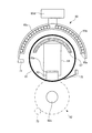
次に、エンドキャップ部材66について述べる。図6(a)はエンドキャップ部材66の平面図であり、図6(b)は図6(a)のYY断面図である。図6に示すように、エンドキャップ部材66は、内径が略同一であり、外径が異なる円筒体を同軸に結合した部材であり、定着ベルト61の両側縁部(両端部)内側に挿入される固定部66aと、固定部66aより外径が大きく形成され、定着ベルト61に装着された際に定着ベルト61よりも半径方向に張り出すように形成されたつば部66dと、回転駆動力が伝達されるギヤ部66bと、内周面に配設され、パッド支持部材64の軸部64aに対して回転可能に結合されるベアリングからなる軸受部66cとを備えている。そして、エンドキャップ部材66は定着ベルト61の両端部に装着され、固定部66aの内側面(定着ベルト61の回転軸と直交する面)がパッド支持部材64の本体両端面と近接対向するように、パッド支持部材64の軸部64aに支持されている。   Next, the end cap member 66 will be described. 6A is a plan view of the end cap member 66, and FIG. 6B is a YY sectional view of FIG. 6A. As shown in FIG. 6, the end cap member 66 is a member in which cylindrical bodies having substantially the same inner diameter and different outer diameters are coaxially coupled, and are inserted into both side edges (both ends) of the fixing belt 61. A fixing portion 66a having a larger outer diameter than the fixing portion 66a, and a flange portion 66d formed so as to protrude in a radial direction from the fixing belt 61 when attached to the fixing belt 61, and a rotational driving force. A gear portion 66b to be transmitted and a bearing portion 66c made of a bearing disposed on the inner peripheral surface and rotatably coupled to the shaft portion 64a of the pad support member 64 are provided. The end cap member 66 is attached to both ends of the fixing belt 61 so that the inner surface of the fixing portion 66a (the surface orthogonal to the rotation axis of the fixing belt 61) is in close proximity to both end surfaces of the pad support member 64. The pad support member 64 is supported by the shaft portion 64a.

エンドキャップ部材66を構成する材質としては、機械的特性に優れ、耐熱性の高い所謂エンジニアリングプラスチックスが適している。例えば、フェノール樹脂、ポリイミド樹脂、ポリアミド樹脂、ポリアミドイミド樹脂、PEEK樹脂、PES樹脂、PPS樹脂、LCP樹脂、それらにガラスやカーボンを含有させた樹脂等を選択することが出来る。
そして、両端部にエンドキャップ部材66が装着された定着ベルト61を用いる本実施の形態の定着装置60においては、図2に示すように、駆動モータ80からの回転駆動力が伝達ギヤ81,82を介してシャフト83に伝達され、シャフト83に結合された伝達ギヤ84,85からエンドキャップ部材66の両端部のギヤ部に伝達される。それによって、エンドキャップ部材66から定着ベルト61に回転駆動力が伝わり、エンドキャップ部材66と定着ベルト61とが一体となって回転駆動される。その際には、定着ベルト61の回転軸がパッド支持部材64の軸部64aの中心軸と一致しているため、定着ベルト61は軸部64aの中心軸周りに滑らかな回転動作を行う。なお、本実施の形態では、駆動モータ80、伝達ギヤ81,82、シャフト83、伝達ギヤ84,85、およびエンドキャップ部材66により駆動部材が構成されている。
As a material constituting the end cap member 66, so-called engineering plastics having excellent mechanical characteristics and high heat resistance are suitable. For example, a phenol resin, a polyimide resin, a polyamide resin, a polyamideimide resin, a PEEK resin, a PES resin, a PPS resin, an LCP resin, a resin containing glass or carbon, or the like can be selected.
In the fixing device 60 of the present embodiment using the fixing belt 61 with the end cap members 66 attached to both ends, the rotational driving force from the driving motor 80 is transmitted to the transmission gears 81 and 82 as shown in FIG. Is transmitted to the shaft 83 through the transmission gears 84 and 85 coupled to the shaft 83 to the gear portions at both ends of the end cap member 66. Accordingly, a rotational driving force is transmitted from the end cap member 66 to the fixing belt 61, and the end cap member 66 and the fixing belt 61 are integrally rotated. At that time, since the rotation axis of the fixing belt 61 coincides with the center axis of the shaft portion 64a of the pad support member 64, the fixing belt 61 performs a smooth rotation operation around the center axis of the shaft portion 64a. In the present embodiment, the drive motor 80, the transmission gears 81 and 82, the shaft 83, the transmission gears 84 and 85, and the end cap member 66 constitute a drive member.

ここで、図7は、図2におけるX2−X2断面図すなわち定着ベルト61の両端部(非通紙域A2に対応)の断面図を示している。なお、この部位では、図2からわかるように加圧ロール62の円筒状部材62aのみが存在するので、加熱ロール62を破線で示している。定着ベルト61の軸方向両端部では、エンドキャップ部材66が配設されることで定着ベルト61の両端部(非通紙域A2)の断面形状が円形を維持している。そして、押圧パッド63は、通紙域A1で用紙Pの剥離に必要な形状を定着ベルト61に与えるためのニップ出口側の弾性層厚さが厚くなった形状(図2参照)から、非通紙域A2に対応する定着ベルト61の内径と同形状のR形状を有するように滑らかに形状が変化している。これにより、通紙域A1から非通紙域A2を介し両端部に向かって定着ベルト61の形状は滑らかに変化する。したがって、定着ベルト61には座屈などが生じることなく、定着ベルト61は滑らかな回転運動を行う。
なお、図2は、通紙域A1に対応する定着装置60の断面図を、また、図7は非通紙域A2に対応する定着装置60の断面図を、それぞれ示しているということができる。
Here, FIG. 7 is a cross-sectional view taken along the line X2-X2 in FIG. 2, that is, a cross-sectional view of both end portions of the fixing belt 61 (corresponding to the non-sheet passing area A2). In addition, in this part, since only the cylindrical member 62a of the pressure roll 62 exists as can be seen from FIG. 2, the heating roll 62 is indicated by a broken line. At both ends in the axial direction of the fixing belt 61, the end cap members 66 are arranged so that the cross-sectional shape of both ends (non-sheet passing area A2) of the fixing belt 61 is maintained circular. Then, the pressing pad 63 does not pass from the shape (see FIG. 2) in which the elastic layer thickness on the nip outlet side for giving the fixing belt 61 a shape necessary for peeling the paper P in the paper passing area A1 is increased. The shape smoothly changes so as to have the same R shape as the inner diameter of the fixing belt 61 corresponding to the paper area A2. As a result, the shape of the fixing belt 61 smoothly changes from the sheet passing area A1 to the both ends via the non-sheet passing area A2. Therefore, the fixing belt 61 performs a smooth rotational movement without causing buckling or the like.
2 is a cross-sectional view of the fixing device 60 corresponding to the paper passing area A1, and FIG. 7 is a cross-sectional view of the fixing device 60 corresponding to the non-paper passing area A2. .

さらに、本実施の形態の定着装置60では、定着ベルト61の半径方向に関して、押圧パッド63の外周面(定着ベルト61の内周面と当接する面)の位置と、エンドキャップ部材66の固定部66aにおける外周面の位置とが略一致するように設定されている。すなわち、押圧パッド63の外周面と固定部66aの外周面とは略同じ平面内に位置するように設定している。それにより、定着ベルト61の回転軸の位置が定着ベルト61の両端部と通紙域A1とで略一致するように設定されるので、定着ベルト61の安定した回転を実現することが可能となる。   Further, in the fixing device 60 of the present embodiment, the position of the outer peripheral surface of the pressing pad 63 (the surface that contacts the inner peripheral surface of the fixing belt 61) and the fixing portion of the end cap member 66 in the radial direction of the fixing belt 61. The position of the outer peripheral surface at 66a is set so as to substantially match. That is, the outer peripheral surface of the pressing pad 63 and the outer peripheral surface of the fixing portion 66a are set so as to be located in substantially the same plane. Accordingly, the position of the rotation axis of the fixing belt 61 is set so as to substantially coincide with both ends of the fixing belt 61 and the sheet passing area A1, so that it is possible to realize stable rotation of the fixing belt 61. .

次に、電磁誘導加熱部材65について述べる。誘導加熱手段の一つとしての電磁誘導加熱部材65は、図3に示すように、定着ベルト61の幅方向に沿って、定着ベルト61の外周面形状に倣った曲面を定着ベルト61側に有する内側ボビン65aと、内側ボビン65aに支持された励磁コイル65bと、外側ボビン65cと、この励磁コイル65bに高周波電流を供給する励磁回路65dとで主要部が構成されている。   Next, the electromagnetic induction heating member 65 will be described. As shown in FIG. 3, the electromagnetic induction heating member 65 as one of the induction heating means has a curved surface on the fixing belt 61 side along the outer peripheral surface shape of the fixing belt 61 along the width direction of the fixing belt 61. The main part is comprised by the inner side bobbin 65a, the exciting coil 65b supported by the inner side bobbin 65a, the outer side bobbin 65c, and the exciting circuit 65d which supplies a high frequency current to this exciting coil 65b.

内側ボビン65aおよび外側ボビン65cは、絶縁性および耐熱性を有する材料からなり、例えば、フェノール樹脂、ポリイミド樹脂、ポリアミド樹脂、ポリアミドイミド樹脂、液晶ポリマー樹脂等を用いることができる。また、励磁コイル65bとしては、例えば、耐熱性の絶縁材料(例えば、ポリイミド樹脂、ポリアミドイミド樹脂等)によって相互に絶縁された直径φ0.5mmの銅線材を複数本束ねたリッツ線を、長円形状や楕円形状、長方形状等の閉ループ状に複数回(例えば、11ターン)巻いたものが用いられる。そして、励磁コイル65bは接着剤によって固められることでその形状を維持しながら内側ボビン65aに固定されている。   The inner bobbin 65a and the outer bobbin 65c are made of a material having insulating properties and heat resistance. For example, a phenol resin, a polyimide resin, a polyamide resin, a polyamideimide resin, a liquid crystal polymer resin, or the like can be used. In addition, as the exciting coil 65b, for example, an ellipse is formed by bundling a plurality of copper wires having a diameter of 0.5 mm that are mutually insulated by a heat-resistant insulating material (for example, polyimide resin, polyamideimide resin, etc.). A shape that is wound a plurality of times (for example, 11 turns) in a closed loop shape such as a shape, an elliptical shape, or a rectangular shape is used. The exciting coil 65b is fixed to the inner bobbin 65a while maintaining its shape by being hardened by an adhesive.

また、励磁コイル65bと、定着ベルト61の導電性層61bとの間の距離は、可能な限り近接させて設置することが磁束の吸収効率を高めるために好ましいことから、これらの距離は5mm以内、例えば、2.5mm程度に設定されている。励磁コイル65bを保持する内側ボビン65aは、通常は電磁誘導の影響を受けない耐熱性の樹脂で作られているため、ある程度の剛性を持たせるために、その厚さは1mm程度必要である。すなわち、励磁コイル65bと定着ベルト61表面との距離を2.5mm程度に設定していても、その内側には内側ボビン65aが存在するため、内側ボビン65aの内面と定着ベルト61との表面距離は1.5mm程度しか開いていないことになる。   Further, the distance between the exciting coil 65b and the conductive layer 61b of the fixing belt 61 is preferably set as close as possible in order to increase the magnetic flux absorption efficiency, so these distances are within 5 mm. For example, it is set to about 2.5 mm. The inner bobbin 65a that holds the exciting coil 65b is usually made of a heat-resistant resin that is not affected by electromagnetic induction. Therefore, the thickness of the inner bobbin 65a needs to be about 1 mm in order to have a certain degree of rigidity. That is, even if the distance between the exciting coil 65b and the surface of the fixing belt 61 is set to about 2.5 mm, the inner bobbin 65a exists on the inner side, and therefore the surface distance between the inner surface of the inner bobbin 65a and the fixing belt 61. Is only open about 1.5 mm.

電磁誘導加熱部材65では、励磁回路65dから励磁コイル65bに高周波電流が供給されると、励磁コイル65bの周囲に磁束が生成消滅を繰り返す。ここで、高周波電流の周波数は、例えば10〜500kHzに設定されるが、本実施の形態では30kHzに設定している。励磁コイル65bからの磁束が定着ベルト61の導電性層61bを横切ると、定着ベルト61の導電性層61bにはその磁界の変化を妨げるような磁界が発生し、それによって導電性層61b内に渦電流が発生する。そして、導電性層61bでは、渦電流(I)によって導電性層61bの表皮抵抗(R)に比例したジュール熱(W=IR)が発生し、定着ベルト61は加熱されることとなる。
なお、その際には、定着ベルト61の温度は、図示しない温度検知センサでの計測値に基づいて、画像形成装置の制御部40が励磁コイル65bに供給する電力量または高周波電流の供給時間等を制御することにより、所定の温度に維持されている。
In the electromagnetic induction heating member 65, when a high frequency current is supplied from the excitation circuit 65d to the excitation coil 65b, the magnetic flux repeatedly generates and disappears around the excitation coil 65b. Here, the frequency of the high-frequency current is set to 10 to 500 kHz, for example, but is set to 30 kHz in the present embodiment. When the magnetic flux from the exciting coil 65b crosses the conductive layer 61b of the fixing belt 61, a magnetic field is generated in the conductive layer 61b of the fixing belt 61 so as to prevent the magnetic field from changing. Eddy current is generated. In the conductive layer 61b, Joule heat (W = I 2 R) proportional to the skin resistance (R) of the conductive layer 61b is generated by the eddy current (I), and the fixing belt 61 is heated. .
In this case, the temperature of the fixing belt 61 is determined based on the measured value of a temperature detection sensor (not shown), the amount of power supplied by the control unit 40 of the image forming apparatus to the exciting coil 65b, the supply time of the high frequency current, or the like. Is maintained at a predetermined temperature.

続いて、本実施の形態に係る定着装置60の動作について説明する。
図1に示す画像形成装置において、画像形成開始の信号が入力されると、定着装置60では、駆動モータ80が駆動されることによりエンドキャップ部材66に駆動力が伝わり、定着ベルト61は回転動作を開始する。ほぼ同時に、励磁回路65dを介して励磁コイル65bに高周波電流が流れ、定着ベルト61の導電性層61bに渦電流が流れて加熱が始まり、定着ベルト61が所定の温度まで加熱されると未定着トナー像を載せた用紙Pが定着ニップ部Nに突入し、熱と圧力により定着される。
このとき、定着ベルト61は、通紙域A1においては図3に示すように、定着ニップ出口部において押圧パッド63がニップ出口側に倒れることにより大きく変形し、用紙Pの定着ベルト61からの剥離が容易になるような構成となっている。また、定着ベルト61の両端部には定着ベルト61の内部に定着ベルト61に駆動を伝えるためのエンドキャップ部材66が嵌合されている。その結果、定着ベルト61は、図7に示すように両端部においては円形形状を保っている。
Next, the operation of the fixing device 60 according to the present embodiment will be described.
In the image forming apparatus shown in FIG. 1, when an image formation start signal is input, in the fixing device 60, a driving force is transmitted to the end cap member 66 by driving the drive motor 80, and the fixing belt 61 rotates. To start. Almost simultaneously, a high-frequency current flows through the exciting coil 65b via the exciting circuit 65d, an eddy current flows through the conductive layer 61b of the fixing belt 61, heating starts, and when the fixing belt 61 is heated to a predetermined temperature, unfixing occurs. The paper P on which the toner image is placed enters the fixing nip portion N and is fixed by heat and pressure.
At this time, as shown in FIG. 3, the fixing belt 61 in the sheet passing area A <b> 1 is largely deformed when the pressing pad 63 falls to the nip outlet side at the fixing nip outlet portion, and the sheet P is peeled from the fixing belt 61. It becomes the structure which becomes easy. Further, end cap members 66 for transmitting driving to the fixing belt 61 are fitted inside the fixing belt 61 at both ends of the fixing belt 61. As a result, the fixing belt 61 maintains a circular shape at both ends as shown in FIG.

このように、軸方向で通紙域A1と両端部(非通紙域A2)とで定着ベルト61の断面形状が異なる。このため、定着ベルト61にかかる歪みを抑えて、定着ベルト61内部の導電性層61bにおけるクラックの発生および定着ベルト61の破損を防止するために、押圧パッド63は図5(b)に示すように、軸方向で通紙域A1と非通紙域A2との境界部から両端部にかけてその断面が滑らかに変化するような形状となっている。このような形状を有する押圧パッド63を使用することで、軸方向全域で通紙域A1と同じ断面形状の押圧パッドを使用した場合と比較すると、定着ベルト61の両端部に発生する歪みを図8に示すように低減することができる。なお、図8において、縦軸は定着ベルト61表面がどのレベルの変形を受けたかを歪みという指標で現したものであり、元の形状φ30を保っている場合の歪みがゼロ、定着ベルト61が凹む方向が圧縮歪み(マイナス側)、定着ベルト61が出っ張る側が引っ張り歪みで(プラス側)である。歪みの測定方法としては、歪みゲージを定着ベルト61の表面に貼りつけ、その歪みゲージが定着ニップ部Nを通過する際に定着ベルト61が変形するのとともに、定着ベルト61に貼り付けられた歪みゲージも変形し、歪みの値として定着ベルト61の変形を測定することができる。   Thus, the cross-sectional shape of the fixing belt 61 is different between the sheet passing area A1 and the both end portions (non-sheet passing area A2) in the axial direction. Therefore, in order to suppress the distortion applied to the fixing belt 61 and prevent the occurrence of cracks in the conductive layer 61b inside the fixing belt 61 and the breakage of the fixing belt 61, the pressing pad 63 is as shown in FIG. In addition, the cross section smoothly changes from the boundary portion between the sheet passing area A1 and the non-sheet passing area A2 to both ends in the axial direction. By using the pressing pad 63 having such a shape, distortion generated at both ends of the fixing belt 61 is reduced as compared with the case where the pressing pad having the same cross-sectional shape as the sheet passing area A1 is used in the entire axial direction. As shown in FIG. In FIG. 8, the vertical axis indicates the level of deformation of the surface of the fixing belt 61 as an index of distortion. The distortion is zero when the original shape φ30 is maintained, and the fixing belt 61 is The direction of depression is compression strain (minus side), and the side where the fixing belt 61 protrudes is tensile strain (plus side). As a method for measuring the strain, a strain gauge is attached to the surface of the fixing belt 61, and when the strain gauge passes through the fixing nip portion N, the fixing belt 61 is deformed and the strain attached to the fixing belt 61 is also measured. The gauge is also deformed, and the deformation of the fixing belt 61 can be measured as a distortion value.

図8から明らかなように、定着ベルト61では、軸方向両端部において大きな歪みが発生する。このような歪みの発生要因としては、例えば本実施の形態に係る定着装置では定着ベルト61の両端部にエンドキャップ部材66を装着し、駆動を行っていることが挙げられる。すなわち、定着ベルト61が剛体でないため、駆動によるストレスが、定着ベルト61の両端部にかかりやすいのである。また、他の歪みの発生要因としては、軸方向中央部(通紙域A1)と両端部(非通紙域A2)とで断面形状が異なる押圧パッド63を用いているために、特に通紙域A1と非通紙域A2との境界近傍において定着ベルト61に繰り返し曲げ力が働いていることも挙げられる。   As is apparent from FIG. 8, the fixing belt 61 is greatly distorted at both ends in the axial direction. As a cause of such distortion, for example, in the fixing device according to the present embodiment, end cap members 66 are attached to both ends of the fixing belt 61 and driven. That is, since the fixing belt 61 is not a rigid body, driving stress is likely to be applied to both ends of the fixing belt 61. Further, as another cause of distortion, since the pressing pad 63 having a different cross-sectional shape is used in the central portion in the axial direction (sheet passing area A1) and the both end portions (non-sheet passing area A2), the sheet passing is particularly performed. Another example is that a bending force is repeatedly applied to the fixing belt 61 in the vicinity of the boundary between the area A1 and the non-sheet passing area A2.

定着ベルト61の周回動作に伴って定着ベルト61の両端部に歪みが繰り返し発生すると、この歪みの発生に伴ってこの部位の導電性層61bが金属疲労を起こし、微小なひびや割れが発生するおそれがある。そして、このようにして導電性層61bに微小なひびや割れが発生すると、これらひびや割れが徐々に成長していく。その結果、導電性層61bには変動磁界による渦電流が生じにくくなり、定着ベルト61の両端部側において加熱不十分による定着不良(コールドオフセット)が発生してしまう。   When distortion is repeatedly generated at both ends of the fixing belt 61 as the fixing belt 61 rotates, the conductive layer 61b at this portion undergoes metal fatigue and micro cracks and cracks are generated. There is a fear. And if a micro crack and a crack generate | occur | produce in the conductive layer 61b in this way, these cracks and a crack will grow gradually. As a result, an eddy current due to a fluctuating magnetic field is less likely to be generated in the conductive layer 61b, and fixing failure (cold offset) due to insufficient heating occurs on both ends of the fixing belt 61.

そこで、本実施の形態では、定着ベルト61の両端部における導電性層61bの状態(ひびや割れの状態)を検知すべく、図2及び図7に示すセンサコイル71を配設している。本実施の形態において、センサコイル71は定着ベルト61と所定のギャップをもって対向配置される。このセンサコイル71は、使用(定着ベルト61の回動)に伴って定着ベルト61の導電性層61bにひびや割れが生じ易くなる場所に設置するのが好ましく、本実施の形態では、図2および図7に示すように、定着ベルト61の軸方向一端部側であって定着ニップ部Nから90°の位置に配設されている。そして、本実施の形態では、センサコイル69が、定着ニップ部Nよりも上流側(定着ニップ入口側)であって、図5に示す押圧パッド63の非通紙域A2に対応する位置に取り付けられている。   Therefore, in the present embodiment, the sensor coil 71 shown in FIGS. 2 and 7 is disposed in order to detect the state (cracked or cracked state) of the conductive layer 61 b at both ends of the fixing belt 61. In the present embodiment, the sensor coil 71 is disposed to face the fixing belt 61 with a predetermined gap. The sensor coil 71 is preferably installed in a place where the conductive layer 61b of the fixing belt 61 is likely to be cracked or cracked with use (rotation of the fixing belt 61). In this embodiment, FIG. As shown in FIG. 7, the fixing belt 61 is disposed at one end side in the axial direction and at a position 90 ° from the fixing nip portion N. In this embodiment, the sensor coil 69 is attached at a position upstream of the fixing nip portion N (on the fixing nip entrance side) and corresponding to the non-sheet passing area A2 of the pressing pad 63 shown in FIG. It has been.

図9は、センサコイル71を含む検知手段あるいはクラック検知部の一つとしてのセンサユニット90の構成を示している。本実施の形態において、コイル部材の一つとしてのセンサコイル71は、中空状のボビン71a、ボビン71aの外周面に巻き回される導線71bを有している。
ボビン71aは、φ10mmで長さ5mmの耐熱性樹脂で構成されている。また、導線71bは、ポリイミドで絶縁被覆が施されたφ1.6mmの銅線からなり、ボビン71aに単層で30ターン巻き回されている。そして、本実施の形態では、定着ベルト61の端部から20mm内側の位置にセンサコイル71を取り付けるとともに、定着ベルト61の表面とセンサコイル71との距離を1mmに設定している。なお、本実施の形態では、ボビン71aの中空状の開口が、定着ベルト61と対向するようにセンサコイル71が配設される。なお、本実施の形態では、円筒形状のボビン71aに導線71bを巻き回すことで、導線71bを螺旋状に形成しているが、これに限られるものではなく、例えば角形のコイルを構成するようにしてもよい。
FIG. 9 shows a configuration of a sensor unit 90 as one of detecting means including a sensor coil 71 or a crack detecting unit. In the present embodiment, the sensor coil 71 as one of the coil members has a hollow bobbin 71a and a conductive wire 71b wound around the outer peripheral surface of the bobbin 71a.
The bobbin 71a is made of a heat-resistant resin having a diameter of 10 mm and a length of 5 mm. The conducting wire 71b is made of a copper wire having a diameter of 1.6 mm and coated with an insulating coating with polyimide, and is wound around the bobbin 71a by a single layer for 30 turns. In this embodiment, the sensor coil 71 is attached to a position 20 mm inside from the end of the fixing belt 61, and the distance between the surface of the fixing belt 61 and the sensor coil 71 is set to 1 mm. In the present embodiment, the sensor coil 71 is disposed so that the hollow opening of the bobbin 71 a faces the fixing belt 61. In the present embodiment, the conducting wire 71b is spirally formed by winding the conducting wire 71b around the cylindrical bobbin 71a. However, the present invention is not limited to this. For example, a rectangular coil is formed. It may be.

また、センサユニット90は、センサコイル71の導線71bに高周波電流を供給する電源の一種としての高周波電源91、高周波電源91より導線71bに供給される電力の力率を計測する力率測定部92とを有している。本実施の形態において、高周波電源91は、定着動作が行われている間すなわち励磁コイル65bによる誘導加熱が行われている間、導線71bに周波数100kHzで実効値が9mA(負荷がない場合)の高周波電流を供給する。また力率測定部92は、計測した力率を制御手段としての制御部40に出力する。   The sensor unit 90 includes a high-frequency power source 91 as a kind of power source that supplies a high-frequency current to the conducting wire 71b of the sensor coil 71, and a power factor measuring unit 92 that measures the power factor of the power supplied from the high-frequency power source 91 to the conducting wire 71b. And have. In the present embodiment, the high-frequency power source 91 has an effective value of 9 mA at a frequency of 100 kHz (when no load is applied) to the conducting wire 71b during the fixing operation, that is, during induction heating by the exciting coil 65b. Supply high frequency current. The power factor measurement unit 92 outputs the measured power factor to the control unit 40 as a control unit.

そして、高周波電源91からセンサコイル71に高周波微電流が流されると、センサコイル71の空芯部には磁束が発生し、その磁束が相対する位置にある定着ベルト61の導電性層61bを貫くことで、導電性層61bには渦電流が流れる。その渦電流により発生した磁束がセンサコイル71の空芯部を貫くことで、センサコイル71に流れる電流と電圧との間に位相のズレθが生じる。この位相のズレθのCOSθが力率である。したがって、力率が大きいほど定着ベルト61は発熱しやすいことになる。一方、定着ベルト61の導電性層61bにクラックが入ると、その部分には渦電流が流れなくなり、力率は低下することになる。   When a high-frequency microcurrent is passed from the high-frequency power source 91 to the sensor coil 71, a magnetic flux is generated in the air core portion of the sensor coil 71 and penetrates the conductive layer 61b of the fixing belt 61 at the position where the magnetic flux is opposed. As a result, an eddy current flows in the conductive layer 61b. The magnetic flux generated by the eddy current passes through the air core portion of the sensor coil 71, thereby causing a phase shift θ between the current flowing through the sensor coil 71 and the voltage. COSθ of this phase shift θ is the power factor. Therefore, the larger the power factor, the easier the fixing belt 61 generates heat. On the other hand, if a crack occurs in the conductive layer 61b of the fixing belt 61, eddy current does not flow in that portion, and the power factor decreases.

定着ベルト61において、発熱層である導電性層61bのクラックは、歪みが大きい部分から発生し、徐々に歪みが小さい部分へと成長してくる。ここで、図10は、定着ベルト61の軸方向端部からの距離をパラメータとしたときの、定着枚数(Run枚数)とそのときにセンサコイル71に供給される電力の力率との関係を示すグラフ図である。
図10から明らかなように、イニシャル状態では、端部からの距離とは無関係に力率は0.16である。そして、定着ベルト61の端部5mmの位置では、定着動作(通紙)を開始してすぐにクラックが入り始め、力率が低下し始める。また、端部10mmの位置では100kpv(10万枚)を過ぎたあたりから力率が低下し始め、端部15mmの位置では250kpvを過ぎたあたりから力率が低下し始めている。さらに、端部20mmの位置では325kpvから力率が低下している。すなわち、上述した理由により定着ベルト61にかかる歪みが最も大きいベルト端部で発生したクラックは非通紙域A2から徐々に軸方向の通紙域A1に向けて成長してくるのである。このクラックが発生する枚数は、定着装置60の使われ方や、定着ベルト61や押圧パッド63などの製造時のバラツキにより異なってくる。
In the fixing belt 61, cracks in the conductive layer 61b, which is a heat generating layer, are generated from a portion having a large strain and gradually grow to a portion having a small strain. Here, FIG. 10 shows the relationship between the number of fixings (the number of Runs) and the power factor of the power supplied to the sensor coil 71 when the distance from the axial end of the fixing belt 61 is used as a parameter. FIG.
As is clear from FIG. 10, in the initial state, the power factor is 0.16 regardless of the distance from the end. Then, at the position of the end portion 5 mm of the fixing belt 61, a crack starts to be generated immediately after the fixing operation (sheet passing) is started, and the power factor starts to decrease. In addition, the power factor starts to decrease after passing 100 kpv (100,000 sheets) at the position of 10 mm end, and the power factor starts to decrease from after about 250 kpv at the position of 15 mm end. Further, the power factor is reduced from 325 kpv at the position of the end 20 mm. That is, for the reason described above, the cracks generated at the belt end portion where the distortion applied to the fixing belt 61 is largest grow gradually from the non-sheet passing area A2 toward the sheet passing area A1 in the axial direction. The number of cracks that are generated varies depending on how the fixing device 60 is used and variations in manufacturing of the fixing belt 61 and the pressing pad 63.

また、図11は、定着ベルト61におけるクラック発生量(発生長さ)をパラメータとしたときの、定着ベルト61の軸方向位置とその温度との関係を示すグラフ図である。本実施の形態において、定着ベルト61の幅(移動方向に直交する方向の長さ)は全長370mmである。そして、この画像形成装置において、最大サイズの用紙Pの通紙幅(最大用紙通紙域)は約300mm(A3SEF、A4LEFの場合に297mm)である。このため、定着ベルト61の軸方向両端部は、実際の定着動作では用紙Pに絶対接しないことになる。   FIG. 11 is a graph showing the relationship between the axial position of the fixing belt 61 and its temperature when the crack generation amount (generation length) in the fixing belt 61 is used as a parameter. In the present embodiment, the width of the fixing belt 61 (the length in the direction orthogonal to the moving direction) is 370 mm in total length. In this image forming apparatus, the paper passing width (maximum paper passing area) of the maximum size paper P is about 300 mm (297 mm in the case of A3SEF and A4LEF). For this reason, both ends of the fixing belt 61 in the axial direction are never in contact with the paper P in the actual fixing operation.

図11に示すように、定着ベルト61におけるクラック発生領域がその軸方向端部から20mm以内(図中実線で示す)であれば、ウォームアップ終了時の軸方向の温度分布はイニシャルと同じ(0.15以上程度)であり、最大用紙通紙域の端部(通紙域A1と非通紙域A2との境界部に対応)でも定着動作に必要な150℃以上の表面温度を確保することができる。一方、定着ベルト61におけるクラック発生領域が端部30mmの位置にまで到達すると、非通紙域A2において渦電流が流れにくくなり、非通紙域A2が加熱されにくくなる結果、隣接する通紙域A1の端部の温度が低下してしまう。その結果、この状態で定着動作を行うと、所謂コールドオフセットが発生してしまう。   As shown in FIG. 11, if the crack occurrence region in the fixing belt 61 is within 20 mm from the axial end thereof (indicated by a solid line in the figure), the axial temperature distribution at the end of warm-up is the same as the initial (0 And ensure a surface temperature of 150 ° C. or higher necessary for the fixing operation even at the end of the maximum sheet passing area (corresponding to the boundary between the sheet passing area A1 and the non-sheet passing area A2). Can do. On the other hand, when the crack occurrence region in the fixing belt 61 reaches the position of the end 30 mm, the eddy current hardly flows in the non-sheet passing region A2, and the non-sheet passing region A2 is hardly heated, so that the adjacent sheet passing region is not heated. The temperature of the end part of A1 will fall. As a result, when the fixing operation is performed in this state, a so-called cold offset occurs.

従来は、コールドオフセットが出たという問題が発生した時点で、定着装置60または定着ベルト61を交換するか、または実際の使われ方や製造上のバラツキなどを含めたときに、最初にクラックが出始める枚数を基準値として、その基準値をベースに、基準値未満から設定された所定の枚数のプリントアウトを行ったら定着ベルト61等を交換させるようにしていた。そのため、実際に故障していないのに無駄に交換されている定着装置60や定着ベルト61が多数あった。   Conventionally, when a problem that a cold offset has occurred occurs, when the fixing device 60 or the fixing belt 61 is replaced, or when actual usage or manufacturing variations are included, cracks are first generated. The number of sheets starting to be taken out is used as a reference value, and the fixing belt 61 and the like are replaced when a predetermined number of prints set from less than the reference value are printed based on the reference value. For this reason, there are a large number of fixing devices 60 and fixing belts 61 that are not actually out of order but are wasted.

そこで、本実施の形態では、定着ベルト61(導電性層61b)の状態によって、上記センサコイル71に供給される電力の力率が変わることに着目し、測定される力率の大きさに基づいて、定着ベルト61のライフを検知している。
では、図12に示すフローチャートを参照しつつ、定着ベルト61のライフ検知について説明する。
画像形成動作の開始に伴って定着動作が開始されると(ステップ101)、制御部40は、高周波電源91によるセンサコイル71への高周波電流の供給を開始する(ステップ102)。また、センサコイル71に高周波電流が供給されるのに伴い、センサコイル71に供給される電力の力率が力率測定部92によって計測され(ステップ103)、計測された力率が制御部40に出力される。次に、制御部40は、力率測定部92によって計測された力率が予め決められた許容値以上であるかを判断する(ステップ104)。ここで、力率が許容値以上であると判断した場合には、ステップ103に戻って定着動作を続行する。一方、ステップ104において、力率が許容値を下回っていると判断した場合には、定着装置60における定着動作を含む画像形成動作全体を停止し(ステップ105)、UI41に定着ベルト61の交換を促すメッセージを表示させる(ステップ106)。なお、制御部40では、センサコイル71に供給される電力の力率の許容値(本例では、例えば0.13が用いられる)を、図示しないROM等に格納している。
Therefore, in the present embodiment, focusing on the fact that the power factor of the electric power supplied to the sensor coil 71 varies depending on the state of the fixing belt 61 (conductive layer 61b), it is based on the magnitude of the measured power factor. Thus, the life of the fixing belt 61 is detected.
Now, the life detection of the fixing belt 61 will be described with reference to the flowchart shown in FIG.
When the fixing operation is started with the start of the image forming operation (step 101), the control unit 40 starts the supply of the high-frequency current to the sensor coil 71 by the high-frequency power source 91 (step 102). Further, as the high frequency current is supplied to the sensor coil 71, the power factor of the power supplied to the sensor coil 71 is measured by the power factor measuring unit 92 (step 103), and the measured power factor is controlled by the control unit 40. Is output. Next, the control unit 40 determines whether or not the power factor measured by the power factor measurement unit 92 is equal to or greater than a predetermined allowable value (step 104). If it is determined that the power factor is equal to or greater than the allowable value, the process returns to step 103 to continue the fixing operation. On the other hand, if it is determined in step 104 that the power factor is below the allowable value, the entire image forming operation including the fixing operation in the fixing device 60 is stopped (step 105), and the fixing belt 61 is replaced with the UI 41. A prompt message is displayed (step 106). In the control unit 40, an allowable value of the power factor of the power supplied to the sensor coil 71 (in this example, 0.13 is used) is stored in a ROM (not shown) or the like.

以上説明したように、本実施の形態では、センサコイル71を用いて、定着ベルト61の導電性層61bに生じるクラックを検知するようにした。そして、定着ベルト61にクラックがある程度発生し、しかも定着ベルト61の最大用紙通紙域の両端部における温度が低下する前の段階で、定着装置60および画像形成装置の動作を停止させるようにした。これにより、定着ベルト61の加熱不良に伴う定着不良(コールドオフセット)を抑えることができる。特に、本実施の形態では、中央部側の通紙域A1と両端部側の非通紙域A2とで押圧パッド63の形状が異なっているため、定着ベルト61の軸方向端部側にストレスがかかりやすい。さらに、本実施の形態では、定着ベルト61の軸方向両端部にエンドキャップ部材66を装着し、これらエンドキャップ部材66を介して定着ベルト61を駆動し、さらに定着ベルト61に従動させて加圧ロール62を回転させるように構成しているため、この点においても定着ベルト61の軸方向端部側にストレスがかかりやすい。したがって、本実施の形態で用いた手法は、このような押圧パッド63あるいは駆動系を有する定着装置60に対して、特に有効であるといえる。   As described above, in this embodiment, the sensor coil 71 is used to detect a crack generated in the conductive layer 61 b of the fixing belt 61. The operation of the fixing device 60 and the image forming apparatus is stopped before the fixing belt 61 is cracked to some extent and before the temperature at both ends of the maximum sheet passing area of the fixing belt 61 decreases. . As a result, fixing failure (cold offset) due to heating failure of the fixing belt 61 can be suppressed. In particular, in the present embodiment, since the shape of the pressing pad 63 is different between the sheet passing area A1 on the center side and the non-sheet passing area A2 on both ends, stress is applied to the axial end side of the fixing belt 61. It is easy to take. Further, in the present embodiment, end cap members 66 are attached to both ends of the fixing belt 61 in the axial direction, the fixing belt 61 is driven through the end cap members 66, and is further driven by the fixing belt 61 to apply pressure. Since the roll 62 is configured to rotate, stress is easily applied to the axial end portion of the fixing belt 61 in this respect as well. Therefore, it can be said that the method used in the present embodiment is particularly effective for such a pressing pad 63 or a fixing device 60 having a drive system.

また、本実施の形態では、定着ベルト61を電磁誘導加熱するために設けられた導電性層61bを利用し、導電性層61bとセンサコイル71との間に生じる磁気特性に基づいて定着ベルト61の導電性層61bに生じるクラックの状態を間接的に検知するようにした。特に、本実施の形態では、センサコイル71に高周波電流を流す際にセンサコイル71に供給される電力の力率を測定しているので、既にある導電性層61bを利用して、定着ベルト61におけるクラックの発生状態および定着ベルト61のライフをより正確に検知することが可能になる。   In the present embodiment, the fixing belt 61 is used based on magnetic characteristics generated between the conductive layer 61 b and the sensor coil 71 using the conductive layer 61 b provided for electromagnetic induction heating of the fixing belt 61. The state of cracks generated in the conductive layer 61b is indirectly detected. In particular, in the present embodiment, the power factor of the electric power supplied to the sensor coil 71 is measured when a high-frequency current is passed through the sensor coil 71. Therefore, the fixing belt 61 is utilized using the existing conductive layer 61b. It is possible to more accurately detect the occurrence of cracks and the life of the fixing belt 61.

さらに、本実施の形態では、センサコイル71を、定着ベルト61の導電性層61bにクラックが最も生じやすい軸方向端部に対応する位置に設けるようにしたので、定着ベルト61のライフをより正確に検知することができる。特に、本実施の形態では、定着ベルト61のライフを検知するものとして、センサコイル71を定着ベルト61の端部から20mmの位置に設定した。このように構成することにより、定着ベルト61の端部20mmの位置にクラックが発生したことを検知することができ、この位置におけるクラックの発生を検知した時点でUI41に交換メッセージを出すなどして、定着装置60または定着ベルト61だけを交換するようにすれば、上述のコールドオフセットの発生を防止でき、かつ故障していない装置や部材を無駄に交換することをなくすことができる。   Further, in the present embodiment, the sensor coil 71 is provided at a position corresponding to the end portion in the axial direction where the crack is most likely to occur in the conductive layer 61b of the fixing belt 61. Therefore, the life of the fixing belt 61 is more accurately determined. Can be detected. In particular, in the present embodiment, the sensor coil 71 is set at a position 20 mm from the end of the fixing belt 61 to detect the life of the fixing belt 61. With this configuration, it is possible to detect the occurrence of a crack at the position of the end 20 mm of the fixing belt 61, and when an occurrence of a crack at this position is detected, an exchange message is issued to the UI 41. If only the fixing device 60 or the fixing belt 61 is replaced, it is possible to prevent the occurrence of the cold offset described above, and it is possible to eliminate unnecessary replacement of devices and members that have not failed.

なお、本実施の形態では、定着動作中は常時コイルセンサ71による力率測定を行うようにしていたが、これに限られるものではなく、例えば所定のプリント枚数毎に力率測定を行って定着ベルト61のライフを検知するようにしてもよい。
また、本実施の形態では、力率が許容値を下回った時点で画像形成動作および定着動作を直ちに停止させるようにしていたが、これに限られるものではなく、例えば力率が第一の許容値を下回った時点でUI41に例えば「まもなく交換時期です」というメッセージを表示させ、その後力率が第二の許容値を下回った時点で画像形成動作及び定着動作を緊急停止させるようにしてもよい。なおここで、第二の許容値は本実施の形態における許容値と同じ値(例えば0.13)に設定することができ、また、第一の許容値は第二の許容値よりもわずかに大きい値(例えば0.14)に設定することができる。
In the present embodiment, the power factor measurement is always performed by the coil sensor 71 during the fixing operation. However, the present invention is not limited to this. For example, power factor measurement is performed for each predetermined number of printed sheets. The life of the belt 61 may be detected.
In this embodiment, the image forming operation and the fixing operation are stopped immediately when the power factor falls below the allowable value. However, the present invention is not limited to this. For example, the power factor is the first allowable value. When the value falls below the value, for example, a message “soon to be replaced” is displayed on the UI 41, and then the image forming operation and the fixing operation are urgently stopped when the power factor falls below the second allowable value. . Here, the second tolerance value can be set to the same value (for example, 0.13) as the tolerance value in the present embodiment, and the first tolerance value is slightly smaller than the second tolerance value. It can be set to a large value (eg 0.14).

実施の形態が適用される画像形成装置の概略構成図である。1 is a schematic configuration diagram of an image forming apparatus to which an embodiment is applied. 実施の形態に係る定着装置の構成を示す概略正面図である。1 is a schematic front view illustrating a configuration of a fixing device according to an embodiment. 定着動作時における定着装置のX1−X1断面図(通紙域での断面図)である。FIG. 6 is a cross-sectional view taken along the line X1-X1 of the fixing device during a fixing operation (a cross-sectional view in a sheet passing area). 定着ベルトの層構成を示す断面図である。FIG. 3 is a cross-sectional view illustrating a layer configuration of a fixing belt. (a)〜(c)は押圧パッドの形状を説明するための図である。(a)-(c) is a figure for demonstrating the shape of a press pad. (a)、(b)はエンドキャップ部材の構造を示す図である。(a), (b) is a figure which shows the structure of an end cap member. 定着動作時における定着装置のX2−X2断面図(非通紙域での断面図)である。FIG. 7 is a cross-sectional view taken along line X2-X2 of the fixing device during a fixing operation (a cross-sectional view in a non-sheet passing area). 実施の形態に係る押圧パッドを用いた場合に、押圧パッドの軸方向各位置で定着ベルトに生じる歪みを示すグラフ図である。FIG. 6 is a graph showing distortion generated in the fixing belt at each position in the axial direction of the pressing pad when the pressing pad according to the embodiment is used. (a)、(b)はセンサコイルの構成の一例を示す図である。(a), (b) is a figure which shows an example of a structure of a sensor coil. 定着ベルトの軸方向端部からの距離をパラメータとしたときの、定着枚数(Run枚数)とそのときにセンサコイルに供給される電力の力率との関係を示すグラフ図である。FIG. 6 is a graph showing the relationship between the number of fixed sheets (Run number) and the power factor of electric power supplied to the sensor coil at that time when the distance from the axial end of the fixing belt is used as a parameter. 定着ベルトにおけるクラック発生量(発生長さ)をパラメータとしたときの、定着ベルトの軸方向位置とその温度との関係を示すグラフ図である。FIG. 6 is a graph showing the relationship between the axial position of the fixing belt and its temperature when the crack generation amount (generation length) in the fixing belt is used as a parameter. 定着ベルトのライフ検知処理の流れを説明するためのフローチャートである。6 is a flowchart for explaining a flow of a fixing belt life detection process.

符号の説明Explanation of symbols

1Y,1M,1C,1K…画像形成ユニット、10…一次転写部、20…二次転写部、40…制御部、41…UI(ユーザインタフェース)、50…用紙トレイ、60…定着装置、61…定着ベルト、61b…導電性層、62…加圧ロール、63…押圧パッド、64…パッド支持部材、65…電磁誘導加熱部材、65b…励磁コイル、66…エンドキャップ部材、71…センサコイル、80…駆動モータ、90…センサユニット、91…高周波電源、92…力率測定部、A1…通紙域、A2…非通紙域、N…定着ニップ部、P…用紙 1Y, 1M, 1C, 1K ... Image forming unit, 10 ... Primary transfer unit, 20 ... Secondary transfer unit, 40 ... Control unit, 41 ... UI (user interface), 50 ... Paper tray, 60 ... Fixing device, 61 ... Fixing belt, 61b ... conductive layer, 62 ... pressure roll, 63 ... pressing pad, 64 ... pad support member, 65 ... electromagnetic induction heating member, 65b ... excitation coil, 66 ... end cap member, 71 ... sensor coil, 80 DESCRIPTION OF SYMBOLS ... Drive motor, 90 ... Sensor unit, 91 ... High frequency power supply, 92 ... Power factor measurement part, A1 ... Paper passing area, A2 ... Non-paper passing area, N ... Fixing nip part, P ... Paper

Claims (6)

記録材上に形成された未定着画像を定着する定着装置であって、
導電性層を有し回動可能に配設される無端状のベルト部材と、
前記ベルト部材の外周面に圧接配置される加圧部材と、
前記導電性層を介して前記ベルト部材を誘導加熱する誘導加熱手段と、
前記誘導加熱手段による誘導加熱に対する前記導電性層の性能低下を検知する検知手段と
を含み、
前記検知手段は、
最大サイズの記録材の通紙域よりも外側で前記ベルト部材に対向配置されるセンサコイルと、
前記センサコイルに高周波電流を供給する電源と、
前記電源により前記センサコイルに前記高周波電流を流したときの電力の力率を測定する力率測定部と
を有することを特徴とする定着装置。
A fixing device for fixing an unfixed image formed on a recording material,
An endless belt member having a conductive layer and rotatably disposed;
A pressure member disposed in pressure contact with the outer peripheral surface of the belt member;
Induction heating means for induction heating the belt member via the conductive layer;
Detecting means for detecting a decrease in performance of the conductive layer with respect to induction heating by the induction heating means,
The detection means includes
A sensor coil disposed opposite to the belt member outside the sheet passing area of the maximum size recording material ;
A power supply for supplying a high-frequency current to the sensor coil;
And a power factor measuring unit that measures a power factor of electric power when the high-frequency current is supplied to the sensor coil by the power source.
前記検知手段によって前記導電性層の性能低下が検知されたときに、前記ベルト部材及び前記加圧部材を用いた定着動作を停止させる制御手段をさらに含むことを特徴とする請求項1記載の定着装置。   The fixing device according to claim 1, further comprising a control unit that stops a fixing operation using the belt member and the pressure member when a decrease in performance of the conductive layer is detected by the detecting unit. apparatus. 金属層を有し回動可能に配設される定着ベルトと、
前記定着ベルトの外周面に圧接することで、当該定着ベルトとの間に未定着画像を担持した記録材を挿通するための定着ニップ部を形成するニップ形成部材と、
前記定着ベルトの内側から前記ニップ形成部材に向けて当該定着ベルトを押圧し、前記定着ニップ部における当該定着ベルトの形状を変形させる押圧パッドと、
前記定着ベルトの軸方向端部側であって当該定着ベルトを用いて定着可能な最大サイズの記録材の通紙域内の温度分布に影響を及ぼす部位の前記金属層におけるクラックの発生を検知するクラック検知部と
を含む定着装置。
A fixing belt having a metal layer and rotatably disposed;
A nip forming member that forms a fixing nip portion for inserting a recording material carrying an unfixed image between the fixing belt and the outer peripheral surface of the fixing belt;
A pressing pad that presses the fixing belt from the inside of the fixing belt toward the nip forming member and deforms the shape of the fixing belt in the fixing nip portion; and
A crack that detects the occurrence of a crack in the metal layer at a portion that affects the temperature distribution in the sheet passing area of the maximum size recording material that can be fixed by using the fixing belt on the axial end side of the fixing belt. A fixing device including a detection unit.
前記定着ベルトの軸方向両端部に嵌合し、当該定着ベルトを駆動するエンドキャップ部材をさらに含み、
前記押圧パッドは、前記記録材が通過する軸方向中央部と当該記録材が通過しない軸方向両端部とで前記定着ベルトに当接する部位の形状が異なることを特徴とする請求項3記載の定着装置。
Fitted in the axial end portions of the fixing belt further seen including an end cap member for driving the fixing belt,
4. The fixing according to claim 3, wherein the pressing pad is different in shape of a portion in contact with the fixing belt at an axial center portion through which the recording material passes and at both axial end portions through which the recording material does not pass. apparatus.
トナー像を形成するトナー像形成部と、A toner image forming unit for forming a toner image;
前記トナー像形成部によって形成されたトナー像を記録材に転写する転写部と、A transfer unit that transfers the toner image formed by the toner image forming unit to a recording material;
前記転写部によって前記記録材上に転写されたトナー像を定着する定着部とを備え、A fixing unit that fixes the toner image transferred onto the recording material by the transfer unit;
前記定着部は、The fixing unit is
導電性層を有し回動可能に配設される無端状のベルト部材と、An endless belt member having a conductive layer and rotatably disposed;
前記ベルト部材の外周面に圧接配置される加圧部材と、A pressure member disposed in pressure contact with the outer peripheral surface of the belt member;
前記導電性層を介して前記ベルト部材を誘導加熱する誘導加熱手段と、Induction heating means for induction heating the belt member via the conductive layer;
前記誘導加熱手段による誘導加熱に対する前記導電性層の性能低下を検知する検知手段とDetecting means for detecting a decrease in performance of the conductive layer with respect to induction heating by the induction heating means;
を含み、Including
前記検知手段は、The detection means includes
最大サイズの記録材の通紙域よりも外側で前記ベルト部材に対向配置されるセンサコイルと、A sensor coil disposed opposite to the belt member outside the sheet passing area of the maximum size recording material;
前記センサコイルに高周波電流を供給する電源と、A power supply for supplying a high-frequency current to the sensor coil;
前記電源により前記センサコイルに前記高周波電流を流したときの電力の力率を測定する力率測定部とA power factor measurement unit for measuring a power factor of electric power when the high frequency current is passed through the sensor coil by the power source;
を有することを特徴とする画像形成装置。An image forming apparatus comprising:
トナー像を形成するトナー像形成部と、A toner image forming unit for forming a toner image;
前記トナー像形成部によって形成されたトナー像を記録材に転写する転写部と、A transfer unit that transfers the toner image formed by the toner image forming unit to a recording material;
前記転写部によって前記記録材上に転写されたトナー像を定着する定着部とを備え、A fixing unit that fixes the toner image transferred onto the recording material by the transfer unit;
前記定着部は、The fixing unit is
金属層を有し回動可能に配設される定着ベルトと、A fixing belt having a metal layer and rotatably disposed;
前記定着ベルトの外周面に圧接することで、当該定着ベルトとの間に未定着画像を担持した記録材を挿通するための定着ニップ部を形成するニップ形成部材と、A nip forming member that forms a fixing nip portion for inserting a recording material carrying an unfixed image between the fixing belt and the outer peripheral surface of the fixing belt;
前記定着ベルトの内側から前記ニップ形成部材に向けて当該定着ベルトを押圧し、前記定着ニップ部における当該定着ベルトの形状を変形させる押圧パッドと、A pressing pad that presses the fixing belt from the inside of the fixing belt toward the nip forming member and deforms the shape of the fixing belt in the fixing nip portion; and
前記定着ベルトの軸方向端部側であって前記定着部で定着可能な最大サイズの記録材の通紙域内の温度分布に影響を及ぼす部位の前記金属層におけるクラックの発生を検知するクラック検知部とA crack detection unit that detects the occurrence of cracks in the metal layer on the axial end portion of the fixing belt and affects the temperature distribution in the sheet passing area of the maximum size recording material that can be fixed by the fixing unit. When
を含むことを特徴とする画像形成装置。An image forming apparatus comprising:
JP2005306318A 2005-10-20 2005-10-20 Fixing device and fixing belt deterioration judging method Expired - Fee Related JP4661516B2 (en)

Priority Applications (1)

Application Number Priority Date Filing Date Title
JP2005306318A JP4661516B2 (en) 2005-10-20 2005-10-20 Fixing device and fixing belt deterioration judging method

Applications Claiming Priority (1)

Application Number Priority Date Filing Date Title
JP2005306318A JP4661516B2 (en) 2005-10-20 2005-10-20 Fixing device and fixing belt deterioration judging method

Publications (3)

Publication Number Publication Date
JP2007114524A JP2007114524A (en) 2007-05-10
JP2007114524A5 JP2007114524A5 (en) 2008-11-13
JP4661516B2 true JP4661516B2 (en) 2011-03-30

Family

ID=38096767

Family Applications (1)

Application Number Title Priority Date Filing Date
JP2005306318A Expired - Fee Related JP4661516B2 (en) 2005-10-20 2005-10-20 Fixing device and fixing belt deterioration judging method

Country Status (1)

Country Link
JP (1) JP4661516B2 (en)

Families Citing this family (7)

* Cited by examiner, † Cited by third party
Publication number Priority date Publication date Assignee Title
US8295752B2 (en) 2009-02-25 2012-10-23 Fuji Xerox Co., Ltd. Fixing device and image forming apparatus
JP5979840B2 (en) * 2011-09-30 2016-08-31 キヤノン株式会社 Replacement fixing belt and fixing belt replacement method
JP5998497B2 (en) * 2012-02-03 2016-09-28 富士ゼロックス株式会社 Fixing device and image forming apparatus using the same
JP5976034B2 (en) * 2014-05-09 2016-08-23 京セラドキュメントソリューションズ株式会社 Fixing apparatus and image forming apparatus having the same
JP6361625B2 (en) * 2015-10-07 2018-07-25 京セラドキュメントソリューションズ株式会社 Fixing apparatus and image forming apparatus
JP6747252B2 (en) * 2015-12-17 2020-08-26 株式会社リコー Fixing device and image forming apparatus
JP6833383B2 (en) 2016-07-28 2021-02-24 キヤノン株式会社 Fixing device

Citations (3)

* Cited by examiner, † Cited by third party
Publication number Priority date Publication date Assignee Title
JP2004029394A (en) * 2002-06-26 2004-01-29 Fuji Xerox Co Ltd Fixing device
JP2004070191A (en) * 2002-08-09 2004-03-04 Fuji Xerox Co Ltd Belt, fixing device, and image forming device
JP2004133370A (en) * 2002-08-09 2004-04-30 Fuji Xerox Co Ltd Fixing belt, its manufacturing method and electromagnetic induction heating and fixing apparatus using same

Patent Citations (3)

* Cited by examiner, † Cited by third party
Publication number Priority date Publication date Assignee Title
JP2004029394A (en) * 2002-06-26 2004-01-29 Fuji Xerox Co Ltd Fixing device
JP2004070191A (en) * 2002-08-09 2004-03-04 Fuji Xerox Co Ltd Belt, fixing device, and image forming device
JP2004133370A (en) * 2002-08-09 2004-04-30 Fuji Xerox Co Ltd Fixing belt, its manufacturing method and electromagnetic induction heating and fixing apparatus using same

Also Published As

Publication number Publication date
JP2007114524A (en) 2007-05-10

Similar Documents

Publication Publication Date Title
JP4609104B2 (en) Fixing apparatus and image forming apparatus
JP5464411B2 (en) Fixing apparatus and image forming apparatus
JP5299690B2 (en) Fixing apparatus and image forming apparatus
JP5943231B2 (en) Fixing apparatus and image forming apparatus
EP2309337B1 (en) Fixing device and image forming apparatus employing the fixing device
JP4635783B2 (en) Fixing device, image forming apparatus
JP5403264B2 (en) Fixing apparatus and image forming apparatus
JP5625406B2 (en) Image forming apparatus
JP4655846B2 (en) Fixing apparatus, image forming apparatus, and fixing method
US8594549B2 (en) Image forming apparatus incorporating a fixing device and contact member to reduce fixing member deformation
JP5625779B2 (en) Fixing apparatus and image forming apparatus
JP5967468B2 (en) Fixing apparatus and image forming apparatus
JP6136221B2 (en) Fixing apparatus and image forming apparatus
JP4356666B2 (en) Heating device and fixing device
JP2011059247A (en) Fixing device and image forming apparatus
JP4661516B2 (en) Fixing device and fixing belt deterioration judging method
JP4600100B2 (en) Apparatus provided with roll member for driving belt member, fixing apparatus, and image forming apparatus
JP4962057B2 (en) Fixing apparatus and image forming apparatus
JP2005077872A (en) Fixing device and image forming apparatus
JP2007079224A (en) Fixing device and fixing method
JP2007057689A (en) Fixing device
JP6611086B2 (en) Fixing apparatus and image forming apparatus
JP4622588B2 (en) Image forming apparatus and power connection switching device abnormality detection method
US8644721B2 (en) Image forming apparatus
JP2009198802A (en) Fixing device and image forming apparatus

Legal Events

Date Code Title Description
A521 Written amendment

Free format text: JAPANESE INTERMEDIATE CODE: A523

Effective date: 20080925

A621 Written request for application examination

Free format text: JAPANESE INTERMEDIATE CODE: A621

Effective date: 20080925

A131 Notification of reasons for refusal

Free format text: JAPANESE INTERMEDIATE CODE: A131

Effective date: 20100914

A521 Written amendment

Free format text: JAPANESE INTERMEDIATE CODE: A523

Effective date: 20101115

TRDD Decision of grant or rejection written
A01 Written decision to grant a patent or to grant a registration (utility model)

Free format text: JAPANESE INTERMEDIATE CODE: A01

Effective date: 20101207

A01 Written decision to grant a patent or to grant a registration (utility model)

Free format text: JAPANESE INTERMEDIATE CODE: A01

A61 First payment of annual fees (during grant procedure)

Free format text: JAPANESE INTERMEDIATE CODE: A61

Effective date: 20101220

R150 Certificate of patent or registration of utility model

Free format text: JAPANESE INTERMEDIATE CODE: R150

FPAY Renewal fee payment (event date is renewal date of database)

Free format text: PAYMENT UNTIL: 20140114

Year of fee payment: 3

LAPS Cancellation because of no payment of annual fees