JP4661514B2 - Image processing apparatus, image processing method, program, and recording medium - Google Patents
Image processing apparatus, image processing method, program, and recording medium Download PDFInfo
- Publication number
- JP4661514B2 JP4661514B2 JP2005294330A JP2005294330A JP4661514B2 JP 4661514 B2 JP4661514 B2 JP 4661514B2 JP 2005294330 A JP2005294330 A JP 2005294330A JP 2005294330 A JP2005294330 A JP 2005294330A JP 4661514 B2 JP4661514 B2 JP 4661514B2
- Authority
- JP
- Japan
- Prior art keywords
- motion vector
- frame
- movement
- inter
- camera
- Prior art date
- Legal status (The legal status is an assumption and is not a legal conclusion. Google has not performed a legal analysis and makes no representation as to the accuracy of the status listed.)
- Expired - Fee Related
Links
Images


Landscapes
- Studio Devices (AREA)
- Image Analysis (AREA)
Description
本発明は、画像処理装置、および、画像処理方法、プログラム、並びに、記録媒体に関し、特に、撮像された動画像のブレの補正を行う場合に用いて好適な、画像処理装置、および、画像処理方法、プログラム、並びに、記録媒体に関する。 The present invention relates to an image processing device, an image processing method, a program, and a recording medium, and more particularly to an image processing device and an image processing that are suitable for use in correcting blurring of a captured moving image. The present invention relates to a method, a program, and a recording medium.
従来から、銀塩カメラやビデオカメラにおいて、ブレを補正する装置が多く提案されている。従来におけるブレの補正の手法は、角速度センサなどを用いてカメラの振動(手ブレ)を検出し、検出されたブレ情報に基づいて、撮影光学系を駆動することにより被写体像がブレるのを防ぐようになされている。 Conventionally, many devices for correcting blurring have been proposed in a silver salt camera and a video camera. Conventional blur correction techniques detect camera vibration (camera shake) using an angular velocity sensor, etc., and drive the photographic optical system based on the detected blur information to prevent the subject image from blurring. It is made to prevent.
また、ビデオカメラにおいては、撮影光学系を駆動する代わりに、撮像センサの画像読み出し範囲を、検出されたブレの方向および速度に合わせてシフトさせる方法も提案されている。 In video cameras, instead of driving the photographic optical system, a method of shifting the image reading range of the imaging sensor in accordance with the detected blur direction and speed has been proposed.
これに対し、撮像して得られた画像を処理する段階において、手ブレとパン・チルトとの動きを区別し、画像処理によって、ブレ画像を補正する技術がある(例えば、特許文献1)。 On the other hand, there is a technique for distinguishing movements between camera shake and pan / tilt and correcting a blurred image by image processing at the stage of processing an image obtained by imaging (for example, Patent Document 1).
例えば、角速度センサなどを用いてカメラの振動を検出する場合などにおいては、パン・チルト等のカメラワークを手ブレの動きと誤って検出してしまう恐れがあり、撮影光学系を駆動させたり、撮像センサの読み出し範囲をシフトさせるような、画像撮像段階における補正を用いた場合、誤検出によって、本来得るべき画を得ることができない可能性がある。これに対して、画像処理を用いてブレてしまった画像を補正する技術は、ブレを誤検出してしまっても、補正されていない画像を残しておいてその画像を表示または出力することができ、さらに、リアルタイムで処理する際に、大容量のメモリを必要としないという点で、画像撮像段階における補正と比較して、非常にメリットがあった。 For example, in the case of detecting camera vibration using an angular velocity sensor or the like, there is a possibility that camera work such as panning and tilting may be mistakenly detected as a movement of a camera shake, driving a photographing optical system, When correction in the image capturing stage that shifts the reading range of the image sensor is used, there is a possibility that an image that should originally be obtained cannot be obtained due to erroneous detection. On the other hand, a technique for correcting an image that has been blurred using image processing can display or output the image while leaving an uncorrected image even if a blur is erroneously detected. In addition, when processing in real time, there is a great advantage compared to correction at the image capturing stage in that a large-capacity memory is not required.
上述した特許文献1に記載されている技術に代表される、画像処理によってブレ画像を補正する手法では、画像から、手ブレを補正するためのカメラの動き検出が重要となってくる。
In a technique for correcting a blurred image by image processing represented by the technique described in
カメラ動きは、本来、図1に示されるように、X軸、Y軸、Z軸回りの回転と、X軸、Y軸、Z軸方向の移動から構成され、各カメラ動きに起因する撮影画像の見かけの変化は異なり、検出される動きベクトルも異なる。例えば、X軸、Y軸回りの回転が存在するとき(いわゆる、パン・チルト)には、図2、図3に示されるように、例えば、縦方向や横方向、または、図示されていないが、これらが合成された斜め方向の動きなど、画面全体に一様の動きを示す動きベクトルが検出され、Z軸回りの回転(いわゆる、光軸回りの回転)では、図4に示されるように、画像中心からの距離に応じた動きベクトルが検出される。 As shown in FIG. 1, the camera motion is originally composed of rotation around the X axis, Y axis, and Z axis, and movement in the X axis, Y axis, and Z axis directions. The apparent change of is different, and the detected motion vector is also different. For example, when there is rotation around the X axis and the Y axis (so-called pan / tilt), as shown in FIGS. 2 and 3, for example, the vertical direction, the horizontal direction, or not shown, As shown in FIG. 4, a motion vector indicating a uniform motion, such as an oblique motion in which these are combined, is detected on the entire screen and rotation around the Z axis (so-called rotation around the optical axis) is performed. A motion vector corresponding to the distance from the image center is detected.
一方、図5に示されるように、カメラの位置に、X軸方向の動きが存在する場合、カメラの移動に起因する各画素の動きの大きさは一律ではなく、カメラと被写体との距離に反比例し、実際のカメラ動きの大きさに比例する。すなわち、カメラの動きが小さい場合よりも大きく動いた場合の方が、各画素の動きは大きくなるが、いずれの場合においても、カメラから近い被写体の動きは、カメラから遠い被写体の動きよりも大きい。また、Y軸方向、Z軸方向のカメラ移動についても、同様である。 On the other hand, as shown in FIG. 5, when there is a movement in the X-axis direction at the camera position, the magnitude of the movement of each pixel due to the movement of the camera is not uniform and depends on the distance between the camera and the subject. It is inversely proportional and proportional to the actual camera movement. That is, the movement of each pixel is larger when the camera moves more than when it is small, but in either case, the movement of the subject close to the camera is larger than the movement of the subject far from the camera. . The same applies to camera movement in the Y-axis direction and the Z-axis direction.
このように、カメラの位置および角度が変化することにより、画像内に様々な動きが発生する。しかしながら、上述した特許文献1に記載されている技術に代表される、画像処理によってブレ画像を補正する従来の技術においては、画像内の変化は様々なカメラ動きに起因しているにも関わらず、カメラの移動は考慮されておらず、画像内の平行移動量をパン、チルトとして推定し、手ブレ補正を行ってきた。
In this way, various movements occur in the image by changing the position and angle of the camera. However, in the conventional technique for correcting a blurred image by image processing, represented by the technique described in
そのため、従来のブレ補正においては、実際にはカメラが移動しているにも関わらず、手ブレしていると判断(誤検出)して、逆補正をかけてしまったり、そもそも、カメラ動き検出自体を誤り、誤って補正してしまう恐れがある。 Therefore, in the conventional blur correction, it is judged that the camera is moving (false detection) even though the camera is actually moving, and reverse correction is applied. There is a risk of correcting itself by mistake.
さらに、カメラ動きが正しく推定でき、カメラ動きをキャンセルする逆補正をかけたとしても、カメラの移動による視点のずれを正しく考慮しなければ、本来撮影者が意図した映像を提示することは困難である。 Furthermore, even if the camera motion can be estimated correctly and reverse correction is applied to cancel the camera motion, it is difficult to present the video originally intended by the photographer unless the viewpoint shift due to camera movement is properly taken into account. is there.
本発明はこのような状況に鑑みてなされたものであり、カメラの動きを考慮して、画像を補正することができるようにするものである。 The present invention has been made in view of such a situation, and makes it possible to correct an image in consideration of the movement of a camera.
本発明の一側面の画像処理装置は、動画像中の複数のフレームを基に、前記動画像を撮像した撮像手段の動きを検出する画像処理装置であって、前記動画像を取得する取得手段と、前記取得手段により取得された前記動画像内の任意の間隔毎の前記フレーム間の動きベクトルであるフレーム間動きベクトルを検出する動きベクトル検出手段と、前記動きベクトル検出手段により検出された前記フレーム間動きベクトルを、前記撮像手段の直進移動または並進移動による第1の動きベクトルと、前記撮像手段の光軸回りの回転を含む回転による第2の動きベクトルとに分離する分離手段と、前記撮像手段の移動を検出して前記撮像手段の移動情報を得る移動情報検出手段とを備え、前記分離手段は、前記動画像中の前記フレームにおける十分遠方の被写体が撮像された領域である遠方領域を推定する遠方領域推定手段と、前記遠方領域において、前記動きベクトル検出手段により検出された前記フレーム間動きベクトルから、前記第2の動きベクトルを除去する除去手段と、前記除去手段により前記第2の動きベクトルが除去された前記フレーム間動きベクトルを基に、前記移動情報検出手段により検出された前記移動情報と、前記第1の動きベクトルとの関係を推定する移動関係推定手段と、前記移動関係推定手段により推定された前記関係に基づいて、前記フレーム間動きベクトルから前記第2の動きベクトルを抽出する回転抽出手段と、前記第2の動きベクトルに基づいて、前記フレーム間動きベクトルから前記第1の動きベクトルを抽出する移動抽出手段とを備える。 An image processing apparatus according to one aspect of the present invention is an image processing apparatus that detects a motion of an imaging unit that captures a moving image based on a plurality of frames in the moving image, and acquires the moving image. And a motion vector detection means for detecting an inter-frame motion vector that is a motion vector between the frames at arbitrary intervals in the moving image acquired by the acquisition means, and the motion vector detection means detected by the motion vector detection means Separating means for separating the inter-frame motion vector into a first motion vector by linear movement or translational movement of the imaging means and a second motion vector by rotation including rotation around the optical axis of the imaging means ; by detecting the movement of the imaging device and a moving information detecting means for obtaining movement information of the imaging means, the separating means is sufficiently far in the frame in the moving image A far region estimation unit that estimates a far region, which is a region in which the subject is imaged, and the second motion vector is removed from the inter-frame motion vector detected by the motion vector detection unit in the far region. A relation between the movement information detected by the movement information detection means based on the inter-frame motion vector from which the second motion vector has been removed by the removal means, and the first motion vector; A movement relation estimation means for estimating the second motion vector from the inter-frame motion vector based on the relation estimated by the movement relation estimation means, and the second motion vector And a movement extracting means for extracting the first motion vector from the inter-frame motion vector .
前記フレームに対して、アフィン変換を用いて前記撮像手段の回転動きを補正して、過去のフレームに変換する回転動き補正手段をさらに備えさせることができ、前記移動情報検出手段には、前記回転動き補正手段により変換された前記過去のフレームと、前記フレームとの動きベクトルを検出し、検出された動きベクトルを反転することにより、前記移動情報を取得させるようにすることができる。 The frame may further include a rotational motion correcting unit that corrects the rotational movement of the imaging unit using affine transformation and converts it into a past frame. The movement information detecting unit includes the rotation The movement information can be acquired by detecting a motion vector between the past frame converted by the motion correction means and the frame, and inverting the detected motion vector.
前記除去手段には、前記フレームの前記遠方領域の各画素において、前記フレームの中心点を回転中心点とした点対称な位置を算出させ、点対称な位置どうしの前記フレーム間動きベクトルを足し合わせさせることにより、前記第2の動きベクトルを除去させるようにすることができる。 The removing means calculates a point-symmetrical position with the center point of the frame as a rotation center point for each pixel in the far region of the frame, and adds the inter-frame motion vectors between the point-symmetrical positions. by so it may be so as to remove the second motion vector.
前記遠方領域推定手段には、前記フレーム間動きベクトルのノルム、角度、または、近傍サンプル点との変化率のうちの少なくとも1つを算出させ、算出された値を統計的に処理させて、前記遠方領域を推定させるようにすることができる。 The said far region estimating means, the norm of the interframe motion vector, angle, or to calculate at least one of the rate of change of the neighboring sample points, statistically to process the calculated value, the A far region can be estimated.
前記遠方領域推定手段には、前記フレーム間動きベクトルのノルムの値が最小を示す位置を求めさせることにより、前記遠方領域を推定させるようにすることができる。 Wherein the distal region estimating means, by causing obtain the position where the value of the norm is the minimum of the motion vector between the frames can be adapted to estimate the far region.
前記遠方領域推定手段には、前記フレーム間動きベクトルのノルムの最小値と、それぞれの位置における前記フレーム間動きベクトルのノルムとの差が、前記フレーム間動きベクトルのノルムの最小値を取る点における変化率以下の値になる領域を、前記遠方領域として推定させるようにすることができる。 The far region estimation means includes a difference between the minimum norm of the inter-frame motion vector and the norm of the inter-frame motion vector at each position at which the minimum value of the norm of the inter-frame motion vector takes a minimum value. An area having a value less than the change rate can be estimated as the far area.
前記遠方領域推定手段は、前記フレーム内の全画素における前記フレーム間動きベクトルのノルムの値を正規化して得られる値を重み付けとして用いさせることにより、前記遠方領域を推定させるようにすることができる。 The far region estimating means, by Rukoto is using a value obtained by normalizing the value of the norm of the motion vector between the frames in all pixels in the frame as a weighting, be adapted to estimate the far region it can.
前記第2の動きベクトルは、前記撮像手段の光軸回りの回転およびパンチルトの回転による動きベクトルであり、前記移動関係推定手段には、前記関係と、前記第2の動きベクトルのうちの前記撮像手段のパンチルトの回転による動きベクトルとを推定させ、前記回転抽出手段には、前記関係と前記撮像手段のパンチルトの回転による動きベクトルに基づいて、前記フレーム間動きベクトルから前記第2の動きベクトルのうちの前記撮像手段の光軸回りの回転による動きベクトルを抽出させるようにすることができる。 It said second motion vector, said a motion vector due to rotation about the optical axis of rotation and pan-tilt of the imaging means, said a transfer relationship estimating means, and the relationship, the imaging of said second motion vector A motion vector due to the rotation of the pan / tilt of the means is estimated , and the rotation extraction means causes the second motion vector to be calculated from the inter-frame motion vector based on the relationship and the motion vector due to the rotation of the pan / tilt of the imaging means. It is possible to extract a motion vector due to rotation of the imaging means around the optical axis .
前記移動関係推定手段には、前記移動情報と、前記フレームの前記第1の動きベクトルとそのフレームより前のフレームの前記第1の動きベクトルの比との前記関係を推定させるようにすることができる。 The movement relation estimation means may be configured to estimate the relation between the movement information and a ratio of the first motion vector of the frame and the first motion vector of a frame before the frame. it can.
本発明の一側面の画像処理方法およびプログラムは、前記動画像を取得する取得ステップと、前記取得ステップの処理により取得された前記動画像内の任意の間隔毎の前記フレーム間の動きベクトルであるフレーム間動きベクトルを検出する動きベクトル検出ステップと、前記動きベクトル検出ステップの処理により検出された前記フレーム間動きベクトルを、前記撮像手段の直進移動または並進移動による第1の動きベクトルと、前記撮像手段の光軸回りの回転を含む回転による第2の動きベクトルとに分離する分離ステップと、前記撮像手段の移動を検出して前記撮像手段の移動情報を得る移動情報検出ステップとを含み、前記分離ステップは、前記動画像中の前記フレームにおける十分遠方の被写体が撮像された領域である遠方領域を推定する遠方領域推定ステップと、前記遠方領域において、前記動きベクトル検出ステップの処理により検出された前記フレーム間動きベクトルから、前記第2の動きベクトルを除去する除去ステップと、前記除去ステップの処理により前記第2の動きベクトルが除去された前記フレーム間動きベクトルを基に、前記移動情報検出ステップの処理により検出された前記移動情報と、前記第1の動きベクトルとの関係を推定する移動関係推定ステップと、前記移動関係推定ステップの処理により推定された前記関係に基づいて、前記フレーム間動きベクトルから前記第2の動きベクトルを抽出する回転抽出ステップと、前記第2の動きベクトルに基づいて、前記フレーム間動きベクトルから前記第1の動きベクトルを抽出する移動抽出ステップとを含む。 One aspect an image processing method and program of the present invention includes an acquisition step of acquiring the moving image is the motion vector between the frames for each arbitrary interval in the moving picture obtained by the process of the acquisition step a motion vector detection step of detecting a motion vector between frames, the interframe motion vector detected by the processing of the motion vector detection step, a first motion vector by linearly moving or translational movement of the imaging means, the imaging A separation step of separating into a second motion vector by rotation including rotation around the optical axis of the means, and a movement information detection step of obtaining movement information of the imaging means by detecting movement of the imaging means, In the separation step, a distant area that is an area where a sufficiently distant subject in the frame in the moving image is imaged. A far region estimation step to be determined, a removal step of removing the second motion vector from the inter-frame motion vector detected by the processing of the motion vector detection step in the far region, and a processing of the removal step Based on the inter-frame motion vector from which the second motion vector has been removed, the movement relationship estimation for estimating the relationship between the movement information detected by the processing of the movement information detection step and the first motion vector A rotation extracting step of extracting the second motion vector from the inter-frame motion vector based on the relationship estimated by the processing of the step, the movement relationship estimating step, and the second motion vector, movement extracting the first motion vector from the motion vector between the frames Including the.
本発明の一側面においては、動画像が取得され、動画像内の任意の間隔毎のフレーム間の動きベクトルであるフレーム間動きベクトルが検出され、フレーム間動きベクトルが、撮像手段の直進移動または並進移動による第1の動きベクトルと、撮像手段の光軸回りの回転を含む回転による第2の動きベクトルとに分離され、撮像手段の移動が検出されて撮像手段の移動情報が得られる。なお、第1の動きベクトルと第2の動きベクトルの分離は、動画像中のフレームにおける十分遠方の被写体が撮像された領域である遠方領域が推定され、遠方領域において、フレーム間動きベクトルから、第2の動きベクトルが除去され、第2の動きベクトルが除去されたフレーム間動きベクトルを基に、移動情報と、第1の動きベクトルとの関係が推定され、その関係に基づいて、フレーム間動きベクトルから第2の動きベクトルが抽出され、第2の動きベクトルに基づいて、フレーム間動きベクトルから第1の動きベクトルが抽出されることにより行われる。 In one aspect of the present invention, a moving image is obtained, is detected inter-frame motion vector is a motion vector between frames for each arbitrary interval in the moving picture, the inter-frame motion vector of the image pickup means straight movement or The first motion vector by translational movement and the second motion vector by rotation including rotation around the optical axis of the imaging unit are separated, and the movement of the imaging unit is detected to obtain movement information of the imaging unit. Note that the separation of the first motion vector and the second motion vector is performed by estimating a far region, which is a region where a sufficiently distant subject is captured in a frame in the moving image, and from the inter-frame motion vector in the far region, The relationship between the movement information and the first motion vector is estimated based on the inter-frame motion vector from which the second motion vector has been removed and the second motion vector has been removed. The second motion vector is extracted from the motion vector, and the first motion vector is extracted from the inter-frame motion vector based on the second motion vector.
なお、画像処理装置は、独立した装置であっても良いし、撮像装置の画像処理を行うブロックであっても良い。また、記録装置は、独立した装置であっても良いし、撮像装置の記録処理を行うブロックであっても良い。また、表示装置も、独立した装置であっても良いし、撮像装置の表示処理を行うブロックであっても良い。 Note that the image processing apparatus may be an independent apparatus or a block that performs image processing of the imaging apparatus. The recording device may be an independent device or a block that performs recording processing of the imaging device. The display device may also be an independent device or a block that performs display processing of the imaging device.
以上のように、本発明の一側面によれば、画像の動きベクトルを検出することができ、特に、動きベクトルを、撮像手段の移動による第1の動きベクトルと、撮像手段の回転による第2の動きベクトルとに分離して、精度よく画像を補正することができる。 As described above, according to one aspect of the present invention, it is possible to detect a motion vector of an image. In particular, the motion vector includes a first motion vector due to movement of the imaging means and a second motion vector due to rotation of the imaging means. It is possible to correct the image with high accuracy by separating the motion vector.
以下に本発明の実施の形態を説明するが、本発明の構成要件と、明細書または図面に記載の実施の形態との対応関係を例示すると、次のようになる。この記載は、本発明をサポートする実施の形態が、明細書または図面に記載されていることを確認するためのものである。従って、明細書または図面中には記載されているが、本発明の構成要件に対応する実施の形態として、ここには記載されていない実施の形態があったとしても、そのことは、その実施の形態が、その構成要件に対応するものではないことを意味するものではない。逆に、実施の形態が構成要件に対応するものとしてここに記載されていたとしても、そのことは、その実施の形態が、その構成要件以外の構成要件には対応しないものであることを意味するものでもない。 Embodiments of the present invention will be described below. Correspondences between constituent elements of the present invention and the embodiments described in the specification or the drawings are exemplified as follows. This description is intended to confirm that the embodiments supporting the present invention are described in the specification or the drawings. Therefore, even if there is an embodiment which is described in the specification or the drawings but is not described here as an embodiment corresponding to the constituent elements of the present invention, that is not the case. It does not mean that the form does not correspond to the constituent requirements. Conversely, even if an embodiment is described here as corresponding to a configuration requirement, that means that the embodiment does not correspond to a configuration requirement other than the configuration requirement. It's not something to do.
本発明の一側面の画像処理装置は、動画像中の複数のフレームを基に、前記動画像を撮像した撮像手段の動きを検出する画像処理装置であって、前記動画像を取得する取得手段(例えば、図7の#1フレームメモリ81)と、前記取得手段により取得された前記動画像内の任意の間隔毎の前記フレーム間の動きベクトルであるフレーム間動きベクトルを検出する動きベクトル検出手段(例えば、図7の動きベクトル検出部83)と、前記動きベクトル検出手段により検出された前記フレーム間動きベクトルを、前記撮像手段の直進移動または並進移動による第1の動きベクトルと、前記撮像手段の光軸回りの回転を含む回転による第2の動きベクトルとに分離する分離手段(例えば、図7のカメラ動き分離部84)と、前記撮像手段の移動を検出して前記撮像手段の移動情報を得る移動情報検出手段(例えば、図7のカメラ移動情報演算部88)と
を備え、
前記分離手段は、
前記動画像中の前記フレームにおける十分遠方の被写体が撮像された領域である遠方領域を推定する遠方領域推定手段(例えば、図12の遠方領域推定手段111)と、
前記遠方領域において、前記動きベクトル検出手段により検出された前記フレーム間動きベクトルから、前記第2の動きベクトルを除去する除去手段(例えば、図12の光軸回りの回転成分除去処理部112)と、
前記除去手段により前記第2の動きベクトルが除去された前記フレーム間動きベクトルを基に、前記移動情報検出手段により検出された前記移動情報と、前記第1の動きベクトルとの関係を推定する移動関係推定手段(例えば、図12のパンチルト成分と並進運動の分離処理部113)と、
前記移動関係推定手段により推定された前記関係に基づいて、前記フレーム間動きベクトルから前記第2の動きベクトルを抽出する回転抽出手段(例えば、図12の光軸回りの回転成分の抽出処理部116)と、
前記第2の動きベクトルに基づいて、前記フレーム間動きベクトルから前記第1の動きベクトルを抽出する移動抽出手段(例えば、図12の直進運動と並進運動の分離処理部117)と
を備える。
An image processing apparatus according to one aspect of the present invention is an image processing apparatus that detects a motion of an imaging unit that captures a moving image based on a plurality of frames in the moving image, and acquires the moving image. (For example, # 1
The separating means includes
A distant area estimating means (for example, a distant area estimating means 111 in FIG. 12) for estimating a distant area that is an area where a sufficiently distant subject in the frame in the moving image is imaged;
In the far region, a removing unit that removes the second motion vector from the inter-frame motion vector detected by the motion vector detecting unit (for example, the rotational component
A movement for estimating a relationship between the movement information detected by the movement information detecting means and the first motion vector based on the inter-frame motion vector from which the second motion vector has been removed by the removing means. Relationship estimation means (for example, pan / tilt component and translational
Based on the relationship estimated by the movement relationship estimation means, a rotation extraction means for extracting the second motion vector from the inter-frame motion vector (for example, a rotation component
A movement extraction means (for example, a linear motion / translational motion
Is provided .
前記フレームに対して、アフィン変換を用いて前記撮像手段の回転動きを補正して、過去のフレームに変換する回転動き補正手段(例えば、図7のカメラ回転動き補正部86)をさらに備えることができ、前記移動情報検出手段は、前記回転動き補正手段により変換された前記過去のフレームと、前記フレームとの動きベクトルを検出し、検出された動きベクトルを反転することにより、前記移動情報を得ることができる。
Rotational motion correction means (for example, the camera rotational
本発明の一側面の画像処理方法およびプログラムは、前記動画像を取得する取得ステップ(例えば、図16のステップS1においてYesと判断されたとき)と、前記取得ステップの処理により取得された前記動画像内の任意の間隔毎の前記フレーム間の動きベクトルであるフレーム間動きベクトルを検出する動きベクトル検出ステップ(例えば、図16のステップS2の処理)と、前記動きベクトル検出ステップの処理により検出された前記フレーム間動きベクトルを、前記撮像手段の直進移動または並進移動による第1の動きベクトルと、前記撮像手段の光軸回りの回転を含む回転による第2の動きベクトルとに分離する分離ステップ(例えば、図16のステップS3の処理)と、前記撮像手段の移動を検出して前記撮像手段の移動情報を得る移動情報検出ステップとを含み、前記分離ステップは、前記動画像中の前記フレームにおける十分遠方の被写体が撮像された領域である遠方領域を推定する遠方領域推定ステップと、前記遠方領域において、前記動きベクトル検出ステップの処理により検出された前記フレーム間動きベクトルから、前記第2の動きベクトルを除去する除去ステップと、前記除去ステップの処理により前記第2の動きベクトルが除去された前記フレーム間動きベクトルを基に、前記移動情報検出ステップの処理により検出された前記移動情報と、前記第1の動きベクトルとの関係を推定する移動関係推定ステップと、前記移動関係推定ステップの処理により推定された前記関係に基づいて、前記フレーム間動きベクトルから前記第2の動きベクトルを抽出する回転抽出ステップと、前記第2の動きベクトルに基づいて、前記フレーム間動きベクトルから前記第1の動きベクトルを抽出する移動抽出ステップとを含む。 The image processing method and the program according to one aspect of the present invention include an acquisition step of acquiring the moving image (for example, when it is determined Yes in step S1 of FIG. 16), and the moving image acquired by the processing of the acquisition step. It is detected by a motion vector detection step (for example, the process of step S2 in FIG. 16) for detecting an inter-frame motion vector that is a motion vector between the frames at arbitrary intervals in the image, and the motion vector detection step A separation step of separating the inter-frame motion vector into a first motion vector by linear movement or translational movement of the imaging unit and a second motion vector by rotation including rotation around the optical axis of the imaging unit ( for example, a process) of step S3 of FIG. 16, the movement information detected and the image pickup means the movement of the imaging means A moving region detecting step for estimating a distant region that is a region where a sufficiently distant subject in the frame in the moving image is imaged, and in the far region, A removal step of removing the second motion vector from the inter-frame motion vector detected by the motion vector detection step, and the inter-frame motion from which the second motion vector has been removed by the processing of the removal step Based on a vector, the movement information estimation step for estimating the relationship between the movement information detected by the processing of the movement information detection step and the first motion vector, and the estimation by the processing of the movement relationship estimation step Based on the relationship, the second motion vector is extracted from the inter-frame motion vector. Comprising a rotating extraction step of, based on the second motion vector and a moving step of extracting said first motion vector from the motion vector between the frames.
以下、図を参照して、本発明の実施の形態について説明する。 Hereinafter, embodiments of the present invention will be described with reference to the drawings.
図6は、本発明を適用した、撮像装置51の構成を示すブロック図である。
FIG. 6 is a block diagram showing a configuration of the
撮像装置51には、画像を処理するためのユニットとして、撮像処理部61、画像データ記録部62、画像処理部63、表示制御部64、および、表示部65が設けられており、さらに、ユーザの操作入力を受ける図示しない操作入力部と、ユーザの操作入力を基に、撮像装置51の全体を制御する図示しない全体制御部とが設けられている。
The
撮像処理部61は、例えば、レンズや、CMOS、またはCCD(Charge-Coupled Device)等の固体撮像素子などからなり、被写体を撮像して、得られた撮像画像データを画像データ記憶部62に供給する。
The
画像データ記憶部62は、例えば、ハードディスクドライブ(HDD)、半導体メモリ、光ディスク、光磁気ディスク、または、磁気ディスクなど、内部に設けられた、または、着脱可能な記録媒体により構成され、撮像処理部61から供給された、補正前の撮像画像データを記憶して、画像処理部63に供給するとともに、画像処理部63において補正されて得られる補正後の画像データを記録する。また、画像データ記憶部63は、図示しない全体制御部の制御に基づいて、記録されている撮像画像データまたは補正後の画像データを表示制御部64に供給する。
The image
画像処理部63は、画像データ記憶部62に記録されている撮像画像データの供給を受け、これを補正する処理を実行する。
The
従来の画像ブレに対する補正処理においては、パン・チルト(図1に示されるカメラのX軸回りの回転およびY軸回りの回転)、および、光軸回りの回転(図1に示されるカメラのZ軸回りの回転)など、画像を撮像するカメラなどの撮像装置の回転動きのみを対象として、そのカメラ動きを検出して補正する手ブレ補正がなされていた。しかし、このような従来の手法では、例えば、車窓からの映像など、画像を撮像するカメラなどの撮像装置が移動しながら撮影する場合や、大きな物体がカメラの撮像範囲内に入ってきた場合などには、これらの動きが想定されていないため、ブレであると誤検出してしまう可能性があった。 In the conventional image blur correction processing, pan / tilt (rotation of the camera shown in FIG. 1 around the X axis and rotation around the Y axis) and rotation around the optical axis (camera Z shown in FIG. 1) are performed. The camera shake correction for detecting and correcting the camera motion is performed only for the rotational motion of an imaging device such as a camera that captures an image, such as rotation around an axis. However, with such a conventional method, for example, when an imaging device such as a camera that captures an image such as a video from a car window is moving or when a large object enters the imaging range of the camera, etc. However, since these movements are not assumed, there is a possibility that it is erroneously detected as blurring.
そこで、画像処理部63は、撮像装置51が移動した時に生じる画面内の被写体の位置関係の変化と、撮像装置51が回転した時に生じる画面内動きを定式化し、分離する処理を行うことにより、画像を補正して、補正された画像データを、表示制御部64、または、画像データ記録部62に供給する。画像処理部63の処理についての詳細は後述する。
Therefore, the
表示制御部64は、画像処理部63または画像データ記録部62から供給される撮像画像データまたは補正された画像データに対応する画像の表示部65への表示を制御する。
The
表示部65は、例えば、LCD(Liquid Crystal Display)などにより構成され、表示制御部64の制御に基づいて、画像を表示する。
The
なお、表示部65は、撮像装置51の外部に独立した表示装置として設けられているものであっても良いことは言うまでもない。さらに、撮像処理部61と画像処理部63とが異なる装置に設けられているものであっても良いことは言うまでもない。
Needless to say, the
図7は、画像処理部63のさらに詳細な構成を示すブロック図である。
FIG. 7 is a block diagram showing a more detailed configuration of the
画像処理部63は、#1フレームメモリ81、#2フレームメモリ82、動きベクトル検出部83、カメラ動き分離部84、フレームディレイ85、カメラ回転動き補正部86、#3フレームメモリ87、カメラ移動情報演算部88、補正情報生成部89、および、補正画像生成部90で構成されている。
The
#1フレームメモリ81は、画像データ記録部62から撮像画像データを取得し、#2フレームメモリ82および動きベクトル検出部83に供給する。
The # 1
#2フレームメモリ82は、#1フレームメモリ81から供給された撮像画像データを1フレーム保持する。
The # 2
なお、ここでは、#2フレームメモリ82に保持されているフレームを基準として、タイミングtにおいて撮像されたフレーム画像データ(tフレーム)であるものとして説明する。すなわち、#1フレームメモリ81に保存されているフレームは、#2フレームメモリ82に保持されているフレームの次のフレーム(t+1フレーム)である。
Here, the description will be made assuming that the frame image data (t frame) is captured at the timing t with reference to the frame held in the # 2
動きベクトル検出部83は、#1フレームメモリ81に保持されているt+1フレームと、#2フレームメモリ82に保持されているtフレームとの、tフレームを基準としたフレーム間の動きベクトルを検出する。動きベクトル検出部83は、例えば、特開2004-134992号公報に記載されているブロックマッチング手法を用いることにより動きベクトルを取得する。なお、動きベクトル検出部83において、動画シーケンスから動きベクトルを検出する手法としては、画素毎、または、ある間隔毎に動きベクトルを検出できれば、たとえば、一般的なブロックマッチング、勾配法、その他の動きベクトル検出方法のいずれであっても構わない。
The motion
カメラ動き分離部84は、動きベクトル検出部83により検出された、tフレームとt+1フレームとの動きベクトルと、後述するカメラ移動情報演算部88により演算される過去フレームのカメラ移動情報を基に、カメラの回転情報とカメラの移動情報を演算し、カメラの回転情報およびカメラの移動情報を補正情報生成部89に供給するとともに、カメラの回転情報を、フレームディレイ85を介して、カメラ回転動き補正部86に供給する。カメラ動き分離部84の詳細については後述する。
The camera
フレームディレイ85は、カメラ動き分離部84から供給されるカメラの回転情報を、1フレームの処理時間分遅延させて、カメラ回転動き補正部86に供給する。すなわち、#2フレームメモリ82に保持されているフレームがtフレームであるとき、フレームディレイ85からカメラ回転動き補正部86に供給されるカメラの回転情報は、t−1フレームにおけるカメラの回転情報である。
The frame delay 85 delays the camera rotation information supplied from the camera
カメラ回転動き補正部86は、#2フレームメモリ82から、tフレームのフレーム画像データを取得し、フレームディレイ85から供給されるt−1フレームにおけるカメラの回転情報を基に、例えば、後述するアフィン変換などを用いて、カメラの回転動きを補正し、補正後のt−1フレームのフレーム画像データを#3フレームメモリ87に供給する。
The camera rotation
#3フレームメモリ87は、回転動きが補正されたt−1フレームのフレーム画像データを保持する。 The # 3 frame memory 87 holds the frame image data of the t−1 frame whose rotational motion is corrected.
カメラ移動情報演算部88は、#2フレームメモリ82から、tフレームのフレーム画像データを取得するとともに、#3フレームメモリ87から、回転動きが補正されたt−1フレームのフレーム画像データを取得して、現在のフレームから過去フレームへの動きベクトルを求めて、カメラ移動情報を演算し、カメラ動き分離部84に供給する。ここで得られた動きベクトルは、撮像装置51の回転成分が完全に除去されているので、オクルージョンの箇所をのぞけば、撮像装置51の移動によって生じた動きベクトルである。
The camera movement
補正情報生成部89は、カメラ動き分離部84から供給されたカメラ回転情報およびカメラ移動情報を基に、tフレームのフレーム画像データのブレを補正するための補正情報を生成し、補正画像生成部90に供給する。
The correction information generation unit 89 generates correction information for correcting blurring of frame image data of t frames based on the camera rotation information and camera movement information supplied from the camera
補正画像生成部90は、#2フレームメモリ82から、tフレームのフレーム画像データを取得し、補正情報生成部89から供給された補正情報を基に、tフレームのフレーム画像データを補正して、画像データ記録部62または表示制御部64に出力する。
The corrected
なお、補正情報生成部89により生成された補正情報を単独で画像データ記録部62に供給して記録しておくようにしても良い。画像データ記録部62には、補正前の撮像画像データも保存されているので、補正情報と補正前の撮像画像データを基に、例えば、異なる装置において補正処理を行うようにしても良い。
The correction information generated by the correction information generation unit 89 may be supplied to the image
次に、図7を用いて説明した画像処理部63における補正の原理について説明する。
Next, the principle of correction in the
カメラ(撮像装置51、または、そのうちの撮像処理部61)の動きには、一般的にX軸、Y軸、Z軸の回転動きと、X軸方向、Y軸方向、Z軸方向のカメラ移動動きとの6自由度の動きが存在する。ここで、図1におけるZ軸方向(光軸方向)のカメラの動きを直進方向の動きと称し、X軸方向のカメラの動きを並進方向の動きと証するものとする。
The movement of the camera (the
例えば、ここでは、カメラの各方向の移動成分を含むカメラ移動モデルを、図8に示されるように、回転動き(光軸回りの回転動きおよびパン・チルト)をしてから、移動動き(直進運動および並進運動)をすると考えるものとする。 For example, here, as shown in FIG. 8, a camera movement model including a movement component in each direction of the camera is rotated (rotated around the optical axis and pan / tilt) and then moved (straightly). Motion and translational motion).
この場合、撮像される画像内に生じる動きベクトルmv(t)(動きベクトルであるので、本来は、mvに対してその上部にベクトルを示す矢印が記載されるべきであるが、ここでは省略し、後述する数式において示す)は、カメラ回転で点がどこに移動するかを定義した関数をR(x)とし、カメラ移動で点がどこに移動するかを定義した関数をT(x)とすると、式(1)により求められる。 In this case, a motion vector mv (t) generated in the captured image (because it is a motion vector, originally, an arrow indicating the vector should be described above mv, but it is omitted here. , Shown in the formula below) is R (x), a function that defines where a point moves with camera rotation, and T (x), a function that defines where a point moves with camera movement, It is obtained by the equation (1).
![]()
![]()
カメラの動きが、パン・チルト、光軸回りの回転の3つのみのとき、カメラの視点は移動しないので、カメラとオブジェクト(被写体)との距離関係は一切変化しない。このようなカメラ動きは一般的にアフィン変換で定義することができる。このことについては、例えば、[A Computational Vision Approach to Image Registration, IEEE TRANSACTIONS ON IMAGE PROCESSING, Vol2 ,No3 , JULY 1993]などにおいても説明されている。 When there are only three camera movements, pan / tilt and rotation around the optical axis, the viewpoint of the camera does not move, so the distance relationship between the camera and the object (subject) does not change at all. Such camera movement can be generally defined by affine transformation. This is also described in, for example, [A Computational Vision Approach to Image Registration, IEEE TRANSACTIONS ON IMAGE PROCESSING, Vol2, No3, JULY 1993].
つまり、ズームを考慮しないカメラの回転動きを考えたとき、撮像された画像フレーム内のパンチルトの回転による動きを(P(t),Q(t))とし、光軸回りの回転をθ(t)として、画像フレームの中心を原点(0,0)とした場合のフレーム内の座標(x,y)は、次の式(2)に従って移動する。 That is, when considering the rotational movement of the camera without considering the zoom, the movement due to the rotation of the pan / tilt in the captured image frame is (P (t), Q (t)), and the rotation around the optical axis is θ (t ), The coordinates (x, y) in the frame when the center of the image frame is the origin (0, 0) move according to the following equation (2).

これに対して、カメラの位置が移動する場合、撮像されて得られるフレーム間の各画素の移動量は、被写体とカメラとの距離に応じて異なるものとなる。 On the other hand, when the position of the camera moves, the amount of movement of each pixel between frames obtained by imaging varies depending on the distance between the subject and the camera.
すなわち、カメラの移動の動きをベクトルV(動きベクトルであるので、本来は、Vに対してその上部にベクトルを示す矢印が記載されるべきであるが、ここでは省略する)を、ベクトルV=(Vx(t),Vy(t),Vz(t))と表記すると、カメラ動きに対して被写体がフレーム上でどのように動くかをモデル化することができる。 That is, the movement of the camera is represented by a vector V (because it is a motion vector, originally, an arrow indicating the vector should be described above V, but it is omitted here). When expressed as (Vx (t), Vy (t), Vz (t)), it is possible to model how the subject moves on the frame with respect to the camera movement.
ここでは、カメラの位置の移動を2方向に分解し、図8を用いて説明したモデルに基づいて、カメラの撮像面と垂直の方向に直進した後、撮像面と並進の方向に移動するという過程をとるものとして考える。 Here, the movement of the camera position is decomposed in two directions, and after moving straight in the direction perpendicular to the imaging surface of the camera based on the model described with reference to FIG. Think of it as a process.
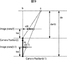
まずは、カメラが撮像面の垂直の方向に移動する直進移動しかしない、つまりベクトルVにVzの成分しか無い場合における各画素の動きのモデルを図9に示す。 First, FIG. 9 shows a model of the movement of each pixel when the camera moves only in a straight direction moving in the direction perpendicular to the imaging surface, that is, when the vector V has only the Vz component.
すなわち、カメラが、図9中、Camera Position(t-1)と示される位置から、Camera Position(t)と示される位置へ、距離Vz移動し、カメラの位置からImage Plane(映像面)までの距離をkwとし、遠方の被写体とCamera Position(t-1)との垂直方向の距離をdaとする。 That is, the camera moves a distance Vz from the position indicated as Camera Position (t-1) in FIG. 9 to the position indicated as Camera Position (t), and from the position of the camera to the image plane (image plane). The distance is kw, and the vertical distance between the far object and Camera Position (t−1) is da.
図9に示されるモデルより、フレーム内の各点の移動は、式(3)で示される。 From the model shown in FIG. 9, the movement of each point in the frame is expressed by equation (3).
次に、カメラが撮像面の並進の方向に移動する、つまりベクトルVにVxの成分しか無い場合における各画素の動きのモデルを図10に示す。 Next, FIG. 10 shows a model of the movement of each pixel when the camera moves in the direction of translation of the imaging surface, that is, when the vector V has only the Vx component.
図10に示されるモデルにおいては、カメラの位置が、(t-1)と示される位置から(t)と示される位置へ、距離Vx移動し、カメラの位置からImage Plane(映像面)までの距離をkwとし、遠方の被写体とカメラとの垂直方向の距離をda−Vzとしている(すなわち、図9を用いて説明した垂直方向の移動の後に並進方向へ移動している)。 In the model shown in FIG. 10, the camera position moves a distance Vx from the position indicated by (t-1) to the position indicated by (t), and from the camera position to the image plane (image plane). The distance is kw, and the distance in the vertical direction between the far object and the camera is da−Vz (that is, the movement is in the translation direction after the vertical movement described with reference to FIG. 9).
このとき、図11に示されるようにして、フレーム内の被写体aの移動量を示すVamベクトル(動きベクトルであるので、本来は、Vamに対してその上部にベクトルを示す矢印が記載されるべきであるが、ここでは省略し、後述する数式において示す)を求めることができるので、これを基に、撮像面の中心を原点とした各画素の点の動きは、式(4)で求められる。 At this time, as shown in FIG. 11, a Vam vector indicating the amount of movement of the subject a in the frame (because it is a motion vector, an arrow indicating the vector should be described above Vam originally. However, it is omitted here and can be obtained in the formulas described later), and based on this, the movement of each pixel point with the center of the imaging surface as the origin can be obtained by Equation (4). .
すなわち、カメラ移動による3次元空間上の動きは、式(3)および式(4)に基づいて、次の式(5)で示される。 That is, the movement in the three-dimensional space due to camera movement is expressed by the following equation (5) based on the equations (3) and (4).
すなわち、カメラの6自由度の動きを、図8に示されるモデルで考えた場合(カメラの6 自由度のある動きを図8のような順番で移動させたものとして分解した場合)の各画素の動きは、上述した式(2)を式(5)に代入することにより、次の式(6)として表現することができる。 That is, each pixel in the case where the movement of the camera with 6 degrees of freedom is considered in the model shown in FIG. 8 (when the movement of the camera with 6 degrees of freedom is moved in the order shown in FIG. 8). Can be expressed as the following equation (6) by substituting equation (2) described above into equation (5).
このように、図8による、撮像された画像内のそれぞれの点の移動が、式(6)から求められたので、x(t-1)からx(t)、および、y(t-1)からy(t)の動きベクトルは、次の式(7)で示される。 Thus, since the movement of each point in the captured image according to FIG. 8 is obtained from the equation (6), x (t−1) to x (t) and y (t−1) ) To y (t) are expressed by the following equation (7).
以上説明した内容を用いて、図7を用いて説明した各部の動作について説明する。 The operation of each unit described with reference to FIG. 7 will be described using the contents described above.
カメラ回転動き補正部86は、式(2)のアフィン変換を基にカメラ回転動きを補正する。すなわち、カメラ回転動き補正部86は、カメラ動き分離部84から、フレームディレイ85を介して供給されるカメラ回転動き情報(P(t),Q(t),θ(t)) に基づいて、#2フレームメモリ82から取得される画像を、式(2)に基づいて変換する。
The camera rotation
そして、カメラ移動情報演算部88では、アフィン変換されて得られた過去フレーム(t−1フレーム)の画像と、現在のフレーム(tフレーム)の画像を用いて、現在のフレームと過去フレームとの動きベクトルを求め、その動きベクトルの方向を反転させる。
Then, the camera movement
ここで得られた動きベクトルは、カメラの回転成分を完全に除去しているので、オクルージョンの箇所をのぞけば、カメラ移動によって生じた動きベクトルである。このカメラ移動情報の動きベクトルdv(動きベクトルであるので、本来は、dvに対してその上部にベクトルを示す矢印が記載されるべきであるが、ここでは省略し、後述する数式において示す)は、式(5)に基づいて、次の式(8)で表現することができる。 Since the motion vector obtained here completely removes the rotation component of the camera, it is a motion vector generated by moving the camera except for the occlusion. The motion vector dv of this camera movement information (because it is a motion vector, originally, an arrow indicating the vector should be described above dv, but it is omitted here and is shown in a mathematical expression described later) Based on the equation (5), it can be expressed by the following equation (8).
式(8)で示される動きベクトルは、特に、十分遠方の領域もしくは直進成分がほとんどない場合において、すなわち、da>>Vzにおける場合において、式(9)で表すことができる。 The motion vector represented by Expression (8) can be expressed by Expression (9) particularly when there is a sufficiently far region or when there is almost no linear component, that is, when da >> Vz.
この式(9)より、十分遠方の領域では、Vx,Vyのカメラ移動情報が、dvx(t),dvy(t)と物体距離と比例の関係にあることが言える。 From this equation (9), it can be said that, in a sufficiently far region, the camera movement information of Vx, Vy is proportional to dvx (t), dvy (t) and the object distance.
そして、カメラ動き分離部84は、カメラ移動情報演算部88により演算された、前フレーム(t−1フレーム)と現在のフレーム(tフレーム)とのカメラ移動情報を用いて、フレーム間で得られた動きベクトルから、カメラの移動による動きと、カメラの回転による動きを分離する。すなわち、カメラ動き分離部84は、上述した式(7)を解く。
The camera
しかしながら、上述した式(7)は、未知数P(t),Q(t),θ(t),da,Vx,Vy,Vzからなるのでこれを解くことは容易ではない。 However, since the equation (7) described above includes unknowns P (t), Q (t), θ (t), da, Vx, Vy, and Vz, it is not easy to solve this.
そこで、カメラ動き分離部84は、様々な未知数が含まれた画像から、統計的にパラメータを求める。
Therefore, the camera
図12は、カメラ動き分離部84が有する機能を説明するための機能ブロック図である。図12を参照して、カメラ動き分離部84が、様々な未知数が含まれた画像から、統計的にパラメータを求める方法の一例について説明する。
FIG. 12 is a functional block diagram for explaining the functions of the camera
カメラ動き分離部84は、遠方領域検出部111、光軸回りの回転成分除去処理部112、パンチルト成分と並進運動の分離処理部113、パンチルト成分取得部114、並進運動による動きベクトル取得部115、光軸回りの回転成分の抽出処理部116、および、直進運動と並進運動の分離処理部117の機能を有している。
The camera
遠方領域検出部111は、統計処理を行うための前処理として、動きベクトル検出部82から供給された、tフレームとt+1フレームとの動きベクトルを基に、フレーム内において、遠方領域を検出する。
The far region detection unit 111 detects a far region in the frame based on the motion vectors of the t frame and the t + 1 frame supplied from the motion
遠方領域検出部111は、遠方領域を検出するために、動きベクトルのノルム、角度、および、変化率を算出する。 The far region detection unit 111 calculates a norm, an angle, and a change rate of the motion vector in order to detect the far region.
まず、動きベクトルノルムvnorm(x, y)は、各画素毎に、動きベクトルのx,y成分を用いて、次の式(10)により算出される。 First, the motion vector norm vnorm (x, y) is calculated by the following equation (10) using the x and y components of the motion vector for each pixel.
![]()
![]()
つぎに、動きベクトルの角度θは、各画素毎に、動きベクトルのx,y成分を用いて、次の式(11)により算出される。 Next, the angle θ of the motion vector is calculated by the following equation (11) using the x and y components of the motion vector for each pixel.
そして、動きベクトルの変化率AveGradは、n×nの領域で隣接する画素8点(間隔=m)(m,nは整数)とのベクトルノルム差分の平均値Gradを式(12)により算出し、平均値Gradを用いて、式(13)により算出する。 The motion vector change rate AveGrad is obtained by calculating an average value Grad of vector norm differences from eight adjacent pixels (spacing = m) (m and n are integers) in an n × n region by the equation (12). Using the average value Grad, calculation is made according to the equation (13).
なお、式(12)において、(i,jは整数)であり、式(13)において、(k,lは整数)である。 In Expression (12), (i, j are integers), and in Expression (13), (k, l are integers).
なお、検出された動きベクトルが誤差を含み、値が暴れてしまう可能性があるので、安定した結果を得るために、例えば、画素毎の動きベクトルの値を、領域毎に平均値か、メディアン値に置き換える処理を、予め行うようにしても良い。 Since the detected motion vector includes an error and the value may be violated, in order to obtain a stable result, for example, the value of the motion vector for each pixel may be an average value or a median for each region. The process of replacing with a value may be performed in advance.
次に、遠方領域検出部111が、動きベクトル検出結果の統計処理により、フレーム内の十分遠方な領域を抽出する方法について、2つの例を示す。 Next, two examples of a method in which the far region detection unit 111 extracts a sufficiently far region in the frame by statistical processing of the motion vector detection result are shown.
まず、第1の例について説明する。 First, the first example will be described.
図13は、実際にベクトルノルムを算出したときのフレーム内のベクトルノルムの分布の例である。遠方領域検出部111は、遠方領域は近方領域と比較して動きベクトルのノルムが小さいという性質を用い、動きベクトルのノルムの最小値を示す位置を、最も遠い点と推定することができる。そして、遠方領域検出部111は、最も遠い点を推定した後、画像内を再度探索し、各画素のベクトルノルムと、最も遠い点のベクトルノルムの差が、最も遠い点のベクトルのノルムの変化率以下になる位置を十分遠方な領域と推定する。 FIG. 13 is an example of the distribution of the vector norm in the frame when the vector norm is actually calculated. The far region detection unit 111 uses the property that the far region has a smaller norm of the motion vector than the near region, and can estimate the position indicating the minimum value of the motion vector norm as the farthest point. Then, after the farthest point is estimated, the far region detection unit 111 searches the image again, and the difference between the vector norm of each pixel and the vector norm of the farthest point is a change in the norm of the vector of the farthest point. A position that falls below the rate is estimated as a sufficiently distant area.
次に、第2の方法について説明する。 Next, the second method will be described.
遠方領域検出部111は、図13の分布自体を重みの係数と見なすことで最も遠い点を推定することができる。例えば、遠方領域検出部111は、各画素の動きベクトルのノルムを以下の式で正規化することで、次の式(14)に示されるようにして、重み係数coef(x, y)を算出することができる。 The far region detection unit 111 can estimate the farthest point by regarding the distribution itself of FIG. 13 as a weighting coefficient. For example, the far region detection unit 111 calculates the weighting coefficient coef (x, y) as shown in the following equation (14) by normalizing the norm of the motion vector of each pixel with the following equation. can do.
式(14)において、vnormmax(x,y),vnormmin(x,y)は、それぞれ、ベクトルノルムの最大、および、最小である。これにより、各画素位置をp(x,y)とすると、以下の式(15)を用いて、最も遠い点P(x,y) を算出することが可能となる。 In equation (14), vnormmax (x, y) and vnormmin (x, y) are the maximum and minimum vector norms, respectively. As a result, when each pixel position is p (x, y), the farthest point P (x, y) can be calculated using the following equation (15).
式(15)におけるw,hは、画像の水平幅および垂直幅である。 In Expression (15), w and h are the horizontal width and the vertical width of the image.
遠方領域検出部111は、第1の方法における場合と同様にして、最も遠い点のベクトルのノルムの変化率以下になる位置を十分遠方な領域と推定する。正規化の方法としては、他に、例えば、平均値vnormave(x,y),最小値vnormmin(x,y)などを用いる方法も考えられる。 In the same manner as in the first method, the far area detection unit 111 estimates a position that is not more than the rate of change of the norm of the vector of the farthest point as a sufficiently far area. As another normalization method, for example, a method using an average value vnormave (x, y), a minimum value vnormmin (x, y), or the like can be considered.
これらの方法により、遠方領域検出部111は、充分遠方な領域を検出することができる。そして、十分遠方な領域においては、カメラ移動による動きベクトルが生じないという条件を用いることができるので、この条件を基に、カメラ回転による動きベクトルのみを推定することが可能となる。したがって、上述した場合と同様の条件により、以降の統計処理で、十分遠方な領域に重みを付けて、カメラ動きを推定することが可能となる。 By these methods, the far region detection unit 111 can detect a sufficiently far region. In a sufficiently distant area, a condition that no motion vector is generated due to camera movement can be used. Therefore, only a motion vector due to camera rotation can be estimated based on this condition. Therefore, it is possible to estimate the camera motion by applying a weight to a sufficiently distant area in the subsequent statistical processing under the same conditions as described above.
そして、光軸回りの回転成分除去処理部112は、十分遠方な領域であるという条件のもと、光軸回りの回転成分を除去する。
Then, the rotation component
すなわち、図8のような移動モデルを想定したとき、ある点(x,y)に対して、式(16)および式(17)に示されるような中止点に対する対称点(x´,y´)を考える。各画素において回転中心からの点対称の点を足しあわせれば、すなわち、式(7)を基にして、式(7)にx(t−1)とy(t−1)を代入したものと、式(7)にx´(t−1)とy´(t−1)を代入したものとを足し合わせることにより、次の式(18)を得ることができる。 That is, when a movement model as shown in FIG. 8 is assumed, a symmetric point (x ′, y ′) with respect to a stop point as shown in Expression (16) and Expression (17) with respect to a certain point (x, y). )think of. If the point symmetry point from the center of rotation is added to each pixel, that is, the result of substituting x (t-1) and y (t-1) into equation (7) based on equation (7) Then, the following equation (18) can be obtained by adding together x ′ (t−1) and y ′ (t−1) into equation (7).
![]()
![]()
![]()
![]()
ここで、十分な遠方の領域もしくは直進成分がほとんどない領域ではVz<<daとみなせるので、次の式(19)が成り立つ。 Here, in a sufficiently far region or a region having almost no straight component, it can be regarded as Vz << da, so the following equation (19) holds.
すなわち、この式(19)は、Vzがdaに対して十分小さい場合について考えると、点対称を利用して回転成分を除去することにより、Vx,da(x,y),P(t)と、Vy,da(x,y),Q(t)の3変数の関数で表現することができることを示している。 That is, when considering the case where Vz is sufficiently small with respect to da, this equation (19) is obtained by removing the rotational component using point symmetry and Vx, da (x, y), P (t) and , Vy, da (x, y), Q (t) can be expressed by a function of three variables.
次に、パンチルト成分と並進運動の分離処理部113は、カメラ移動情報演算部88から供給された過去フレームとのカメラ移動情報を取得し、式(19)を基に、Vx,da(x,y),P(t)の3変数を求め、パンチルトと並進運動とのそれぞれの成分を分離する。
Next, the pan / tilt component and translational motion
すなわち、十分遠方の領域、または、直進移動がほとんどない場合においては、上述した式(9)が成り立つので、式(9)から得られるカメラ移動情報の動きベクトルdv(t)(動きベクトルであるので、本来は、dvに対してその上部にベクトルを示す矢印が記載されるべきであるが、ここでは省略し、後述する数式において示す)より、式(19)は次の式(20)として表すことができる。 That is, in the case of a sufficiently far region or when there is almost no straight movement, the above-described equation (9) is established, and therefore the motion vector dv (t) (the motion vector of the camera movement information obtained from the equation (9) Therefore, originally, an arrow indicating a vector should be described at the top of dv with respect to dv, but it is omitted here and shown in the mathematical formula described later). Can be represented.
これは、速度比Vx(t)/Vx(t−1)とパンチルト成分P(t),Q(t)の方程式と見なすことができる。この方程式を解くための具体的な方法の例を以下に3つ示す。 This can be regarded as an equation of the speed ratio Vx (t) / Vx (t−1) and the pan / tilt components P (t) and Q (t). Three examples of specific methods for solving this equation are shown below.
まず、1つ目の方法として、mv(t)+mv´(t)とdv(t)+dv´(t)との関係(動きベクトルであるので、本来は、mv,mv´,dv,dv´に対してその上部にベクトルを示す矢印が記載されるべきであるが、ここでは省略する。以下同様)を、速度比とパンチルトの座標上に写像する方法について説明する。 First, as a first method, the relationship between mv (t) + mv ′ (t) and dv (t) + dv ′ (t) (because it is a motion vector, originally mv, mv ′, dv, dv ′ An arrow indicating a vector should be described on the upper part of the image, but here it will be omitted. The same applies hereinafter) on the coordinates of the speed ratio and pan / tilt will be described.
図14に示されるように、速度比とパンチルト成分を2軸とする座標系を考える。各点で与えられるmv(t)とdv(t)は、座標上で直線と表現することができる。すなわち、十分遠方の領域、または、直進移動がほとんどない場合において、速度比とパンチルト成分の座標系で、これらの直線が一番多く交わる交点(例えば、図中点αで示される座標)を求めることにより、速度比とパンチルト成分を推定することができる。 As shown in FIG. 14, a coordinate system having two axes of a speed ratio and a pan / tilt component is considered. Mv (t) and dv (t) given at each point can be expressed as straight lines on the coordinates. That is, in a sufficiently far region or when there is almost no straight movement, the intersection (for example, the coordinate indicated by the point α in the figure) where these straight lines intersect most frequently is obtained in the coordinate system of the speed ratio and pan / tilt component. Thus, the speed ratio and the pan / tilt component can be estimated.
次に、2つ目の方法として、mv(t)+mv´(t)とdv(t)+dv´(t)との統計値を利用する方法について説明する。 Next, as a second method, a method using statistical values of mv (t) + mv ′ (t) and dv (t) + dv ′ (t) will be described.
mv(t)とdv(t)のヒストグラムは、式(20)より、図15に示されるようになる。すなわち、図15において、mv(t)+mv´(t)とdv(t)+dv´(t)とのそれぞれの値の平均値の差がパンチルト成分を表し、mv(t)+mv´(t)とdv(t)+dv´(t)とのそれぞれの標準偏差の比が速度比を表す。これは、式(21)、および、式(22)で示される。 The histogram of mv (t) and dv (t) is as shown in FIG. 15 from the equation (20). That is, in FIG. 15, the difference between the average values of mv (t) + mv ′ (t) and dv (t) + dv ′ (t) represents the pan / tilt component, and mv (t) + mv ′ (t) The ratio of the standard deviations of dv (t) + dv ′ (t) represents the speed ratio. This is shown by Formula (21) and Formula (22).
2つ目の方法においては、このようにして、速度比とパンチルト成分を推定することができる。 In the second method, the speed ratio and the pan / tilt component can be estimated in this way.
そして、3つ目の方法として、Vx(t)/Vx(t−1)=1を初期値として、パンチルト成分を求める方法について説明する。 As a third method, a method of obtaining a pan / tilt component using Vx (t) / Vx (t−1) = 1 as an initial value will be described.
カメラの速度が1フレームの間で急激に変化することは少ない。このことを利用して、カメラがフレーム間で等速運動をしているという仮定を立てると、Vx(t)/Vx(t−1)=1と考えることができる。このことを利用すると、平均値もしくはヒストグラムの最頻値がパンチルト成分と考えることができる。 The camera speed rarely changes abruptly during one frame. Taking this into consideration, it can be considered that Vx (t) / Vx (t−1) = 1, assuming that the camera is moving at a constant speed between frames. By utilizing this, the average value or the mode value of the histogram can be considered as the pan / tilt component.
パンチルト成分と並進運動の分離処理部113は、例えば、これらの3つの方法のうちのいずれかを用いることにより、速度比とパンチルト成分を求めることができる。
The pan / tilt component and translational motion
そして、パンチルト成分取得部114は、パンチルト成分と並進運動の分離処理部113により分離されたパンチルト成分を取得する。
The pan / tilt
並進運動による動きベクトル取得部115は、パンチルト成分と並進運動の分離処理部113により分離された並進運動による動きベクトルを取得する。
The translation vector motion
そして、光軸回りの回転成分の抽出処理部116は、パンチルト成分取得部114から供給されたパンチルト成分、および、並進運動による動きベクトル取得部115から供給された並進運動による動きベクトルを基に、動きベクトル検出部82から供給された、tフレームとt+1フレームとの動きベクトルから、光軸回りの回転成分を抽出する。
Then, the rotation component
上述した演算により、パンチルト成分と速度比が求められているので、式(7)より、十分遠方の領域または直進移動がほとんどない場合、da(x,y)>>Vz(t)と見なせるので、次の式(23)が成り立つ。 Since the pan / tilt component and the speed ratio are obtained by the above-described calculation, it can be regarded as da (x, y) >> Vz (t) from the equation (7) when there is almost no far enough area or straight movement. The following equation (23) holds.
光軸回りの回転成分の抽出処理部116は、この式(23)の方程式を解くことにより、光軸回りの回転成分θ(t)を求め、カメラ回転情報を補正情報生成部89およびフレームディレイ85に供給することができる。
The rotation component
直進運動と並進運動の分離処理部117は、動きベクトル検出部82から供給された、tフレームとt+1フレームとの動きベクトルから、直進運動と並進運動の分離を行う。
The straight motion / translation motion
上述した演算により、パンチルト成分、光軸回りの回転成分が求められているので、上述した式(6)にパンチルト成分、光軸回りの回転成を代入して変形すると、次の式(24)を得ることができる。 Since the pan / tilt component and the rotation component around the optical axis are obtained by the above calculation, if the pan / tilt component and the rotation component around the optical axis are substituted into the above equation (6) and transformed, the following equation (24) Can be obtained.
そして、式(24)を式(9)を用いて変形すると、次の式(25)を得ることができる。 Then, when the formula (24) is transformed using the formula (9), the following formula (25) can be obtained.
この式(25)は、Vx(t)とVz(t)/kwの方程式とみなすことができる。直進運動と並進運動の分離処理部117は、図14を用いて説明した場合と同様にして写像を行ったり、図15を用いて説明した場合と同様にして統計値を利用することなどにより、式(25)からVx(t)とVz(t)/kwとを求める計算を実行することができ、得られたカメラ移動情報を、補正情報生成部89に供給する。
This equation (25) can be regarded as an equation of Vx (t) and Vz (t) / kw. The
以上説明した処理により、図12を用いて説明したカメラ動き分離部84は、撮像装置51の回転と移動を分離して、カメラ回転情報とカメラ移動情報を生成することができる。
Through the processing described above, the camera
図7に示される画像処理63においては、このようにして得られたカメラ回転情報とカメラ移動情報を基にして、補正情報生成部89において、撮像装置51の回転のみならず、移動を考慮した補正情報が生成され、補正画像生成部90において、フレーム画像が補正されて出力される。
In the
これにより、撮像装置51の動き検出精度が向上し、また、手ブレを効果的に除去して画像を補正することができる。また、動き推定結果に基づき、補正画像を生成するので、画像処理63の処理により、本来撮影者が意図した見え方で、補正画像を提示することが可能になる。
Thereby, the motion detection accuracy of the
次に、図16のフローチャートを参照して、撮像装置51が画像処理装置63を用いて撮像画像データの補正を行う場合の処理について説明する。
Next, with reference to the flowchart of FIG. 16, processing when the
ステップS1において、画像処理装置63の#1フレームメモリ81は、撮像処理部61により画像が撮像され、画像データ記録部62を介して、撮像画像データが供給されたか否かを判断する。ステップS1において、画像が撮像されていないと判断された場合、画像が撮像されたと判断されるまで、ステップS1の処理が繰り返される。
In step S <b> 1, the # 1
ステップS1において、画像が撮像されたと判断された場合、ステップS2において、動きベクトル検出部83およびカメラ移動情報演算部88は、動きベクトルを検出する。
If it is determined in step S1 that an image has been captured, in step S2, the motion
具体的には、動きベクトル検出部83は、図17に示される、tとt+1のフレームの動きベクトルを、上述したようにして検出し、カメラ移動情報演算部88は、カメラ回転動き補正部86の処理によりカメラの回転動きが補正されたt−1フレームの画像データを基に、図17に示される、tとt−1のフレームの動きベクトルを、上述したようにして検出し、それぞれ、カメラ動き分離部84に供給する。
Specifically, the motion
ステップS3において、カメラ動き分離部84は、図12乃至図15を用いて説明したようにして、カメラ移動とカメラ回転を分離して推定し、その結果得られるカメラ移動情報およびカメラ回転情報を、補正情報生成部89に供給する。
In step S3, the camera
ステップS4において、画像処理装置63の#1フレームメモリ81は、次のフレームがあるか否かを判断する。
In step S4, the # 1
ステップS4において、次のフレームがあると判断された場合、ステップS5において、補正情報生成部89は、カメラ移動情報およびカメラ回転情報を基に、撮像画像データを補正するための補正情報を生成し、補正画像生成部90に供給する。補正画像生成部90は、補正情報生成部89から供給された補正情報を基に、撮像画像データの補正を行う。
If it is determined in step S4 that there is a next frame, in step S5, the correction information generation unit 89 generates correction information for correcting the captured image data based on the camera movement information and the camera rotation information. , And supplied to the corrected
そして、ステップS6において、正画像生成部90は、補正された画像を、画像データ記録部62または表示制御部64に出力し、処理は、ステップS2に戻り、それ以降の処理が繰り返される。
In step S6, the normal
ステップS4において、次のフレームがないと判断された場合、ステップS7において、補正情報生成部89は、カメラ移動情報およびカメラ回転情報を基に、撮像画像データを補正するための補正情報を生成し、補正画像生成部90に供給する。補正画像生成部90は、補正情報生成部89から供給された補正情報を基に、撮像画像データの補正を行う。
If it is determined in step S4 that there is no next frame, in step S7, the correction information generation unit 89 generates correction information for correcting the captured image data based on the camera movement information and the camera rotation information. , And supplied to the corrected
そして、ステップS8において、正画像生成部90は、補正された画像を、画像データ記録部62または表示制御部64に出力し、処理は終了される。
In step S8, the normal
このような処理により、撮像装置51の動きを、カメラ回転動きとカメラ並進動きを区別して推定することができるので、撮像装置51の動き検出精度が向上し、また、手ブレのみを純粋に(すなわち、撮像装置51の移動と誤検出することなく)、効果的に除去して画像を補正することができる。
By such processing, the motion of the
また、撮像装置51の動き推定結果に基づき補正画像を生成するので、画像処理63における処理により、本来撮影者が意図した見え方で、補正画像を提示することが可能になる。さらに、画像処理63において統計処理を用いていることから、カメラ動き推定のロバスト性が高い。
Further, since the corrected image is generated based on the motion estimation result of the
このようにして、本発明を適用した撮像装置51においては、撮影光学系を駆動させたり、撮像センサの読み出し範囲をシフトさせるような、画像撮像段階における補正と比較して、ブレを誤検出してしまっても、補正されていない画像を残しておいてその画像を表示または出力することができるという優位点と、リアルタイムで処理する際に、大容量のメモリを必要としないという優位点を備えるとともに、実際にはカメラが移動しているにも関わらず、手ブレしていると判断(誤検出)して、逆補正をかけてしまったり、そもそも、カメラ動き検出自体を誤り、誤って補正してしまうことを防止して、精度の良いブレの補正が可能となる。
In this way, in the
また、本発明は、手ブレのみならず、シャッター時間内において被写体が動いてしまうようなブレも、基本的に同様にして補正することができるのはいうまでもない。 In the present invention, it is needless to say that not only camera shake but also blur that causes the subject to move within the shutter time can be corrected basically in the same manner.
上述した一連の処理は、ハードウエアにより実行させることもできるし、ソフトウェアにより実行させることもできる。この場合、上述した処理は、図18に示されるようなパーソナルコンピュータ500により実行される。
The series of processes described above can be executed by hardware or can be executed by software. In this case, the processing described above is executed by a
図18において、CPU(Central Processing Unit)501は、ROM(Read Only Memory)502に記憶されているプログラム、または、記憶部508からRAM(Random Access Memory)503にロードされたプログラムに従って各種の処理を実行する。RAM503にはまた、CPU501が各種の処理を実行する上において必要なデータなどが適宜記憶される。
In FIG. 18, a CPU (Central Processing Unit) 501 performs various processes according to a program stored in a ROM (Read Only Memory) 502 or a program loaded from a
CPU501、ROM502、およびRAM503は、内部バス504を介して相互に接続されている。この内部バス504にはまた、入出力インターフェース505も接続されている。
The
入出力インターフェース505には、キーボード、マウスなどよりなる入力部506、CRT,LCDなどよりなるディスプレイ、スピーカなどよりなる出力部507、ハードディスクなどより構成される記憶部508、並びに、モデム、ターミナルアダプタなどより構成される通信部509が接続されている。通信部509は、電話回線やCATVを含む各種のネットワークを介しての通信処理を行う。
The input /
入出力インターフェース505にはまた、必要に応じてドライブ510が接続され、磁気ディスク、光ディスク、光磁気ディスク、あるいは半導体メモリなどによりなるリムーバブルメディア521が適宜装着され、それから読み出されたコンピュータプログラムが、必要に応じて記憶部508にインストールされる。
A
一連の処理をソフトウェアにより実行させる場合には、そのソフトウェアを構成するプログラムが、ネットワークやプログラム格納媒体からインストールされる。 When a series of processing is executed by software, a program constituting the software is installed from a network or a program storage medium.
このプログラム格納媒体は、図18に示されるように、コンピュータとは別に、ユーザにプログラムを提供するために配布される、プログラムが記録されているリムーバブルメディア521よりなるパッケージメディアにより構成されるだけでなく、装置本体に予め組み込まれた状態でユーザに提供される、プログラムが記録されているROM502や記憶部508が含まれるハードディスクなどで構成される。
As shown in FIG. 18, the program storage medium is configured only by a package medium including a
また、本明細書において、記録媒体に記録されるプログラムを記述するステップは、記載された順序に沿って時系列的に行われる処理はもちろん、必ずしも時系列的に処理されなくとも、並列的あるいは個別に実行される処理をも含むものである。 Further, in the present specification, the step of describing the program recorded on the recording medium is not limited to the processing performed in chronological order according to the described order, but may be performed in parallel or It also includes processes that are executed individually.
なお、本明細書において、システムとは、複数の装置により構成される装置全体を表すものである。 In the present specification, the term “system” represents the entire apparatus constituted by a plurality of apparatuses.
なお、本発明の実施の形態は、上述した実施の形態に限定されるものではなく、本発明の要旨を逸脱しない範囲において種々の変更が可能である。 The embodiment of the present invention is not limited to the above-described embodiment, and various modifications can be made without departing from the gist of the present invention.
51 撮像装置, 63 画像処理部, 83 動きベクトル検出部, 84 カメラ動き分離部, 86 カメラ回転動き補正部, 88 カメラ移動情報演算部, 89 補正情報生成部, 90 補正画像生成部, 111 遠方領域検出部, 112 光軸回りの回転成分除去処理部, 113 パンチルト成分と並進運動の分離処理部, 116 光軸回りの回転成分の抽出処理部, 117 直進運動と並進運動の分離処理部 51 imaging device, 63 image processing unit, 83 motion vector detection unit, 84 camera motion separation unit, 86 camera rotation motion correction unit, 88 camera movement information calculation unit, 89 correction information generation unit, 90 correction image generation unit, 111 far region Detection unit, 112 Rotational component removal processing unit around optical axis, 113 Separation processing unit of pan / tilt component and translational motion, 116 Extraction processing unit of rotational component around optical axis, 117 Separation processing unit of linear motion and translational motion
Claims (12)
前記動画像を取得する取得手段と、
前記取得手段により取得された前記動画像内の任意の間隔毎の前記フレーム間の動きベクトルであるフレーム間動きベクトルを検出する動きベクトル検出手段と、
前記動きベクトル検出手段により検出された前記フレーム間動きベクトルを、前記撮像手段の直進移動または並進移動による第1の動きベクトルと、前記撮像手段の光軸回りの回転を含む回転による第2の動きベクトルとに分離する分離手段と、
前記撮像手段の移動を検出して前記撮像手段の移動情報を得る移動情報検出手段と
を備え、
前記分離手段は、
前記動画像中の前記フレームにおける十分遠方の被写体が撮像された領域である遠方領域を推定する遠方領域推定手段と、
前記遠方領域において、前記動きベクトル検出手段により検出された前記フレーム間動きベクトルから、前記第2の動きベクトルを除去する除去手段と、
前記除去手段により前記第2の動きベクトルが除去された前記フレーム間動きベクトルを基に、前記移動情報検出手段により検出された前記移動情報と、前記第1の動きベクトルとの関係を推定する移動関係推定手段と、
前記移動関係推定手段により推定された前記関係に基づいて、前記フレーム間動きベクトルから前記第2の動きベクトルを抽出する回転抽出手段と、
前記第2の動きベクトルに基づいて、前記フレーム間動きベクトルから前記第1の動きベクトルを抽出する移動抽出手段と
を備える
画像処理装置。 In an image processing apparatus that detects the movement of an imaging unit that captured the moving image based on a plurality of frames in the moving image,
Obtaining means for obtaining the moving image;
Motion vector detection means for detecting an inter-frame motion vector that is a motion vector between the frames at an arbitrary interval in the moving image acquired by the acquisition means;
The inter-frame motion vector detected by the motion vector detection means is a second motion caused by rotation including rotation of the imaging means including a first motion vector due to linear movement or translational movement and rotation around the optical axis of the imaging means. Separating means for separating the vector ;
A movement information detecting means for detecting movement of the imaging means to obtain movement information of the imaging means ,
The separating means includes
A far region estimation means for estimating a far region which is a region where a sufficiently far subject in the frame in the moving image is captured;
Removing means for removing the second motion vector from the inter-frame motion vector detected by the motion vector detecting means in the far region;
A movement for estimating a relationship between the movement information detected by the movement information detecting means and the first motion vector based on the inter-frame motion vector from which the second motion vector has been removed by the removing means. Relationship estimation means;
Rotation extraction means for extracting the second motion vector from the inter-frame motion vector based on the relation estimated by the movement relation estimation means;
Movement extracting means for extracting the first motion vector from the inter-frame motion vector based on the second motion vector;
An image processing apparatus comprising:
前記移動情報検出手段は、前記回転動き補正手段により変換された前記過去のフレームと、前記フレームとの動きベクトルを検出し、検出された動きベクトルを反転することにより、前記移動情報を得る
請求項1に記載の画像処理装置。 The frame further comprises rotational motion correction means for correcting the rotational movement of the imaging means using affine transformation and converting it to a past frame,
The movement information detection unit detects the motion vector between the past frame converted by the rotational motion correction unit and the frame, and obtains the movement information by inverting the detected motion vector. the image processing apparatus according to 1.
請求項1に記載の画像処理装置。 The removing means calculates a point-symmetric position with respect to the center point of the frame at each pixel in the far region of the frame, and adds the inter-frame motion vectors between the point-symmetric positions. the image processing apparatus according to claim 1 of removing the second motion vector.
請求項1に記載の画像処理装置。 The far region estimating means, the norm of the motion vector between the frames, angle or calculates at least one of the rate of change of the neighboring sample points, the calculated value is treated statistically, the far The image processing apparatus according to claim 1 , wherein the area is estimated.
請求項4に記載の画像処理装置。 The far region estimating means, by obtaining a position value of the norm is the minimum of the motion vector between the frames, the image processing apparatus according to claim 4 for estimating the far region.
請求項5に記載の画像処理装置。 The far region estimating means changes at a point where the minimum value of the norm of the interframe motion vector, the difference between the norm of the interframe motion vector at each location, a minimum value of the norm of the motion vector between the frames The image processing apparatus according to claim 5 , wherein an area having a value equal to or less than a rate is estimated as the far area.
請求項4に記載の画像処理装置。 5. The image according to claim 4 , wherein the far region estimation unit estimates the far region by using, as a weight, a value obtained by normalizing a norm value of the interframe motion vector in all pixels in the frame. Processing equipment.
前記移動関係推定手段は、前記関係と、前記第2の動きベクトルのうちの前記撮像手段のパンチルトの回転による動きベクトルとを推定し、
前記回転抽出手段は、前記関係と前記撮像手段のパンチルトの回転による動きベクトルに基づいて、前記フレーム間動きベクトルから前記第2の動きベクトルのうちの前記撮像手段の光軸回りの回転による動きベクトルを抽出する
請求項1に記載の画像処理装置。 The second motion vector is a motion vector generated by rotation around the optical axis of the imaging unit and rotation of pan tilt.
The movement relationship estimation means estimates the relationship and a motion vector due to a rotation of the pan / tilt of the imaging means in the second motion vector ,
The rotation extracting means is based on the relationship and a motion vector due to pan-tilt rotation of the imaging means, and a motion vector due to rotation around the optical axis of the imaging means from the inter-frame motion vector to the second motion vector. The image processing device according to claim 1 , wherein the image processing device extracts the image.
請求項1に記載の画像処理装置。The image processing apparatus according to claim 1.
前記動画像を取得する取得ステップと、
前記取得ステップの処理により取得された前記動画像内の任意の間隔毎の前記フレーム間の動きベクトルであるフレーム間動きベクトルを検出する動きベクトル検出ステップと、
前記動きベクトル検出ステップの処理により検出された前記フレーム間動きベクトルを、前記撮像手段の直進移動または並進移動による第1の動きベクトルと、前記撮像手段の光軸回りの回転を含む回転による第2の動きベクトルとに分離する分離ステップと、
前記撮像手段の移動を検出して前記撮像手段の移動情報を得る移動情報検出ステップと
を含み、
前記分離ステップは、
前記動画像中の前記フレームにおける十分遠方の被写体が撮像された領域である遠方領域を推定する遠方領域推定ステップと、
前記遠方領域において、前記動きベクトル検出ステップの処理により検出された前記フレーム間動きベクトルから、前記第2の動きベクトルを除去する除去ステップと、
前記除去ステップの処理により前記第2の動きベクトルが除去された前記フレーム間動きベクトルを基に、前記移動情報検出ステップの処理により検出された前記移動情報と、前記第1の動きベクトルとの関係を推定する移動関係推定ステップと、
前記移動関係推定ステップの処理により推定された前記関係に基づいて、前記フレーム間動きベクトルから前記第2の動きベクトルを抽出する回転抽出ステップと、
前記第2の動きベクトルに基づいて、前記フレーム間動きベクトルから前記第1の動きベクトルを抽出する移動抽出ステップと
を含む
画像処理方法。 In an image processing method of an image processing apparatus for detecting a motion of an imaging unit that has captured the moving image based on a plurality of frames in the moving image,
An acquisition step of acquiring the moving image;
A motion vector detection step of detecting an inter-frame motion vector that is a motion vector between the frames at an arbitrary interval in the moving image acquired by the processing of the acquisition step ;
The inter-frame motion vector detected by the processing of the motion vector detection step is converted into a first motion vector obtained by linear movement or translational movement of the imaging means and a second result obtained by rotation including rotation around the optical axis of the imaging means. And a separation step that separates into motion vectors ,
A movement information detecting step of detecting movement of the imaging means to obtain movement information of the imaging means;
Including
The separation step includes
A far region estimation step for estimating a far region, which is a region in which a sufficiently far subject in the frame in the moving image is imaged;
A removal step of removing the second motion vector from the inter-frame motion vector detected by the motion vector detection step in the far region;
Relationship between the movement information detected by the movement information detection step and the first motion vector based on the inter-frame motion vector from which the second motion vector has been removed by the removal step process A movement relationship estimation step for estimating
A rotation extraction step of extracting the second motion vector from the inter-frame motion vector based on the relationship estimated by the processing of the movement relationship estimation step;
The second based on the motion vector, the image processing method comprising a moving step of extracting said first motion vector from the motion vector between the frames.
前記動画像を取得する取得ステップと、
前記取得ステップの処理により取得された前記動画像内の任意の間隔毎の前記フレーム間の動きベクトルであるフレーム間動きベクトルを検出する動きベクトル検出ステップと、
前記動きベクトル検出ステップの処理により検出された前記フレーム間動きベクトルを、前記撮像手段の直進移動または並進移動による第1の動きベクトルと、前記撮像手段の光軸回りの回転を含む回転による第2の動きベクトルとに分離する分離ステップと、
前記撮像手段の移動を検出して前記撮像手段の移動情報を得る移動情報検出ステップと
を含み、
前記分離ステップは、
前記動画像中の前記フレームにおける十分遠方の被写体が撮像された領域である遠方領域を推定する遠方領域推定ステップと、
前記遠方領域において、前記動きベクトル検出ステップの処理により検出された前記フレーム間動きベクトルから、前記第2の動きベクトルを除去する除去ステップと、
前記除去ステップの処理により前記第2の動きベクトルが除去された前記フレーム間動きベクトルを基に、前記移動情報検出ステップの処理により検出された前記移動情報と、前記第1の動きベクトルとの関係を推定する移動関係推定ステップと、
前記移動関係推定ステップの処理により推定された前記関係に基づいて、前記フレーム間動きベクトルから前記第2の動きベクトルを抽出する回転抽出ステップと、
前記第2の動きベクトルに基づいて、前記フレーム間動きベクトルから前記第1の動きベクトルを抽出する移動抽出ステップと
を含む
処理をコンピュータに実行させるプログラム。 A program for causing a computer to execute processing for detecting camera movement from a plurality of frames in a moving image captured by an imaging unit,
An acquisition step of acquiring the moving image;
A motion vector detection step of detecting an inter-frame motion vector that is a motion vector between the frames at an arbitrary interval in the moving image acquired by the processing of the acquisition step ;
The inter-frame motion vector detected by the processing of the motion vector detection step is converted into a first motion vector obtained by linear movement or translational movement of the imaging means and a second result obtained by rotation including rotation around the optical axis of the imaging means. And a separation step that separates into motion vectors ,
A movement information detecting step of detecting movement of the imaging means to obtain movement information of the imaging means;
Including
The separation step includes
A far region estimation step for estimating a far region, which is a region in which a sufficiently far subject in the frame in the moving image is imaged;
A removal step of removing the second motion vector from the inter-frame motion vector detected by the motion vector detection step in the far region;
Relationship between the movement information detected by the movement information detection step and the first motion vector based on the inter-frame motion vector from which the second motion vector has been removed by the removal step process A movement relationship estimation step for estimating
A rotation extraction step of extracting the second motion vector from the inter-frame motion vector based on the relationship estimated by the processing of the movement relationship estimation step;
The second based on the motion vector, a program for executing the processing including a mobile extracting said first motion vector from the motion vector between the frames to the computer.
Priority Applications (1)
| Application Number | Priority Date | Filing Date | Title |
|---|---|---|---|
| JP2005294330A JP4661514B2 (en) | 2005-10-07 | 2005-10-07 | Image processing apparatus, image processing method, program, and recording medium |
Applications Claiming Priority (1)
| Application Number | Priority Date | Filing Date | Title |
|---|---|---|---|
| JP2005294330A JP4661514B2 (en) | 2005-10-07 | 2005-10-07 | Image processing apparatus, image processing method, program, and recording medium |
Publications (3)
| Publication Number | Publication Date |
|---|---|
| JP2007104516A JP2007104516A (en) | 2007-04-19 |
| JP2007104516A5 JP2007104516A5 (en) | 2008-11-20 |
| JP4661514B2 true JP4661514B2 (en) | 2011-03-30 |
Family
ID=38030979
Family Applications (1)
| Application Number | Title | Priority Date | Filing Date |
|---|---|---|---|
| JP2005294330A Expired - Fee Related JP4661514B2 (en) | 2005-10-07 | 2005-10-07 | Image processing apparatus, image processing method, program, and recording medium |
Country Status (1)
| Country | Link |
|---|---|
| JP (1) | JP4661514B2 (en) |
Families Citing this family (7)
| Publication number | Priority date | Publication date | Assignee | Title |
|---|---|---|---|---|
| KR101375067B1 (en) | 2005-08-09 | 2014-03-17 | 파나소닉 주식회사 | Recording medium, playback appatatus, method and program |
| JP5251410B2 (en) * | 2008-10-03 | 2013-07-31 | 株式会社ニコン | Camera work calculation program, imaging apparatus, and camera work calculation method |
| JP5364927B2 (en) * | 2009-04-24 | 2013-12-11 | 京セラ株式会社 | Motion compensation apparatus and method |
| JP5940392B2 (en) * | 2012-06-28 | 2016-06-29 | オリンパス株式会社 | Blur correction apparatus and method |
| JP2017034587A (en) * | 2015-08-05 | 2017-02-09 | ソニー株式会社 | Signal processing device and signal processing method |
| JP6455474B2 (en) * | 2016-03-25 | 2019-01-23 | カシオ計算機株式会社 | Image processing apparatus, image processing method, and program |
| JP7143703B2 (en) | 2018-09-25 | 2022-09-29 | トヨタ自動車株式会社 | Image processing device |
Citations (7)
| Publication number | Priority date | Publication date | Assignee | Title |
|---|---|---|---|---|
| JP2000010141A (en) * | 1998-06-26 | 2000-01-14 | Ricoh Co Ltd | Digital camera with camera shake correction mechanism |
| JP2000224462A (en) * | 1999-02-02 | 2000-08-11 | Minolta Co Ltd | Camera system |
| JP2001307104A (en) * | 2000-04-26 | 2001-11-02 | Nippon Hoso Kyokai <Nhk> | Object extraction device for moving image |
| JP2003209736A (en) * | 2002-01-15 | 2003-07-25 | Ricoh Co Ltd | Imaging apparatus |
| WO2004062270A1 (en) * | 2002-12-26 | 2004-07-22 | Mitsubishi Denki Kabushiki Kaisha | Image processor |
| JP2005027046A (en) * | 2003-07-02 | 2005-01-27 | Sony Corp | Image processor and image processing method |
| JP2005269419A (en) * | 2004-03-19 | 2005-09-29 | Canon Inc | Method and device for estimating image deformation |
Family Cites Families (6)
| Publication number | Priority date | Publication date | Assignee | Title |
|---|---|---|---|---|
| JP2677312B2 (en) * | 1991-03-11 | 1997-11-17 | 工業技術院長 | Camera work detection method |
| JP3405788B2 (en) * | 1993-03-04 | 2003-05-12 | 株式会社東芝 | Video encoding device and video decoding device |
| JP3513950B2 (en) * | 1993-12-14 | 2004-03-31 | 株式会社ニコン | Image stabilization camera |
| JP3502525B2 (en) * | 1997-02-20 | 2004-03-02 | 日本電信電話株式会社 | Camera parameter estimation method |
| JPH1144700A (en) * | 1997-07-25 | 1999-02-16 | Sanyo Electric Co Ltd | Speed-measuring apparatus, automatic tracking system using the apparatus and display system for estimated arrival position |
| JPH11195125A (en) * | 1997-12-26 | 1999-07-21 | Canon Inc | Picture processor and method therefor and computer readable storage medium |
-
2005
- 2005-10-07 JP JP2005294330A patent/JP4661514B2/en not_active Expired - Fee Related
Patent Citations (7)
| Publication number | Priority date | Publication date | Assignee | Title |
|---|---|---|---|---|
| JP2000010141A (en) * | 1998-06-26 | 2000-01-14 | Ricoh Co Ltd | Digital camera with camera shake correction mechanism |
| JP2000224462A (en) * | 1999-02-02 | 2000-08-11 | Minolta Co Ltd | Camera system |
| JP2001307104A (en) * | 2000-04-26 | 2001-11-02 | Nippon Hoso Kyokai <Nhk> | Object extraction device for moving image |
| JP2003209736A (en) * | 2002-01-15 | 2003-07-25 | Ricoh Co Ltd | Imaging apparatus |
| WO2004062270A1 (en) * | 2002-12-26 | 2004-07-22 | Mitsubishi Denki Kabushiki Kaisha | Image processor |
| JP2005027046A (en) * | 2003-07-02 | 2005-01-27 | Sony Corp | Image processor and image processing method |
| JP2005269419A (en) * | 2004-03-19 | 2005-09-29 | Canon Inc | Method and device for estimating image deformation |
Also Published As
| Publication number | Publication date |
|---|---|
| JP2007104516A (en) | 2007-04-19 |
Similar Documents
| Publication | Publication Date | Title |
|---|---|---|
| EP2640057B1 (en) | Image processing device, image processing method and program | |
| EP2640059B1 (en) | Image processing device, image processing method and program | |
| CN107852462B (en) | Camera module, solid-state imaging element, electronic apparatus, and imaging method | |
| US10043245B2 (en) | Image processing apparatus, imaging apparatus, control method, and information processing system that execute a re-anti-shake process to remove negative influence of an anti-shake process | |
| US7646891B2 (en) | Image processor | |
| KR100866963B1 (en) | Method for stabilizing digital image which can correct the horizontal shear distortion and vertical scale distortion | |
| JP6170395B2 (en) | Imaging apparatus and control method thereof | |
| JP4661514B2 (en) | Image processing apparatus, image processing method, program, and recording medium | |
| US8559751B2 (en) | Method and device for removing motion blur effects | |
| EP2053844A1 (en) | Image processing device, image processing method, and program | |
| US20090225174A1 (en) | Image processing apparatus, image processing method, hand shake blur area estimation device, hand shake blur area estimation method, and program | |
| JP2011029735A (en) | Image processor, imaging device, and image processing method | |
| JP2008520117A (en) | Digital image acquisition system having means for determining camera motion blur function | |
| WO2010100677A1 (en) | Image processing device and shake amount calculation method | |
| CN113556464B (en) | Shooting method and device and electronic equipment | |
| JP6202879B2 (en) | Rolling shutter distortion correction and image stabilization processing method | |
| JP6282133B2 (en) | Imaging device, control method thereof, and control program | |
| JP2007104516A5 (en) | ||
| JP2011097217A (en) | Motion correction device and method therefor | |
| JP6178646B2 (en) | Imaging apparatus and image shake correction processing method | |
| KR20150146424A (en) | Method for determining estimated depth in an image and system thereof | |
| KR20100046544A (en) | Image distortion compensation method and apparatus | |
| US10764500B2 (en) | Image blur correction device and control method | |
| JP2008310418A (en) | Image processing apparatus, image processing program, and digital camera equipped therewith | |
| JP4743601B2 (en) | Moving image processing device |
Legal Events
| Date | Code | Title | Description |
|---|---|---|---|
| A521 | Request for written amendment filed |
Free format text: JAPANESE INTERMEDIATE CODE: A523 Effective date: 20081002 |
|
| A621 | Written request for application examination |
Free format text: JAPANESE INTERMEDIATE CODE: A621 Effective date: 20081002 |
|
| A977 | Report on retrieval |
Free format text: JAPANESE INTERMEDIATE CODE: A971007 Effective date: 20100709 |
|
| A131 | Notification of reasons for refusal |
Free format text: JAPANESE INTERMEDIATE CODE: A131 Effective date: 20100805 |
|
| A521 | Request for written amendment filed |
Free format text: JAPANESE INTERMEDIATE CODE: A523 Effective date: 20100917 |
|
| TRDD | Decision of grant or rejection written | ||
| A01 | Written decision to grant a patent or to grant a registration (utility model) |
Free format text: JAPANESE INTERMEDIATE CODE: A01 Effective date: 20101207 |
|
| A01 | Written decision to grant a patent or to grant a registration (utility model) |
Free format text: JAPANESE INTERMEDIATE CODE: A01 |
|
| A61 | First payment of annual fees (during grant procedure) |
Free format text: JAPANESE INTERMEDIATE CODE: A61 Effective date: 20101220 |
|
| FPAY | Renewal fee payment (event date is renewal date of database) |
Free format text: PAYMENT UNTIL: 20140114 Year of fee payment: 3 |
|
| R250 | Receipt of annual fees |
Free format text: JAPANESE INTERMEDIATE CODE: R250 |
|
| R250 | Receipt of annual fees |
Free format text: JAPANESE INTERMEDIATE CODE: R250 |
|
| LAPS | Cancellation because of no payment of annual fees |