JP4659221B2 - Heavy machinery tires - Google Patents
Heavy machinery tires Download PDFInfo
- Publication number
- JP4659221B2 JP4659221B2 JP2000605044A JP2000605044A JP4659221B2 JP 4659221 B2 JP4659221 B2 JP 4659221B2 JP 2000605044 A JP2000605044 A JP 2000605044A JP 2000605044 A JP2000605044 A JP 2000605044A JP 4659221 B2 JP4659221 B2 JP 4659221B2
- Authority
- JP
- Japan
- Prior art keywords
- ply
- working
- plies
- reinforcement
- width
- Prior art date
- Legal status (The legal status is an assumption and is not a legal conclusion. Google has not performed a legal analysis and makes no representation as to the accuracy of the status listed.)
- Expired - Fee Related
Links
Images

Classifications
-
- B—PERFORMING OPERATIONS; TRANSPORTING
- B60—VEHICLES IN GENERAL
- B60C—VEHICLE TYRES; TYRE INFLATION; TYRE CHANGING; CONNECTING VALVES TO INFLATABLE ELASTIC BODIES IN GENERAL; DEVICES OR ARRANGEMENTS RELATED TO TYRES
- B60C9/00—Reinforcements or ply arrangement of pneumatic tyres
- B60C9/18—Structure or arrangement of belts or breakers, crown-reinforcing or cushioning layers
- B60C9/20—Structure or arrangement of belts or breakers, crown-reinforcing or cushioning layers built-up from rubberised plies each having all cords arranged substantially parallel
- B60C9/2003—Structure or arrangement of belts or breakers, crown-reinforcing or cushioning layers built-up from rubberised plies each having all cords arranged substantially parallel characterised by the materials of the belt cords
- B60C9/2006—Structure or arrangement of belts or breakers, crown-reinforcing or cushioning layers built-up from rubberised plies each having all cords arranged substantially parallel characterised by the materials of the belt cords consisting of steel cord plies only
-
- B—PERFORMING OPERATIONS; TRANSPORTING
- B60—VEHICLES IN GENERAL
- B60C—VEHICLE TYRES; TYRE INFLATION; TYRE CHANGING; CONNECTING VALVES TO INFLATABLE ELASTIC BODIES IN GENERAL; DEVICES OR ARRANGEMENTS RELATED TO TYRES
- B60C9/00—Reinforcements or ply arrangement of pneumatic tyres
- B60C9/18—Structure or arrangement of belts or breakers, crown-reinforcing or cushioning layers
- B60C9/20—Structure or arrangement of belts or breakers, crown-reinforcing or cushioning layers built-up from rubberised plies each having all cords arranged substantially parallel
- B60C9/2003—Structure or arrangement of belts or breakers, crown-reinforcing or cushioning layers built-up from rubberised plies each having all cords arranged substantially parallel characterised by the materials of the belt cords
- B60C9/2009—Structure or arrangement of belts or breakers, crown-reinforcing or cushioning layers built-up from rubberised plies each having all cords arranged substantially parallel characterised by the materials of the belt cords comprising plies of different materials
-
- B—PERFORMING OPERATIONS; TRANSPORTING
- B60—VEHICLES IN GENERAL
- B60C—VEHICLE TYRES; TYRE INFLATION; TYRE CHANGING; CONNECTING VALVES TO INFLATABLE ELASTIC BODIES IN GENERAL; DEVICES OR ARRANGEMENTS RELATED TO TYRES
- B60C9/00—Reinforcements or ply arrangement of pneumatic tyres
- B60C9/18—Structure or arrangement of belts or breakers, crown-reinforcing or cushioning layers
- B60C9/20—Structure or arrangement of belts or breakers, crown-reinforcing or cushioning layers built-up from rubberised plies each having all cords arranged substantially parallel
- B60C2009/2038—Structure or arrangement of belts or breakers, crown-reinforcing or cushioning layers built-up from rubberised plies each having all cords arranged substantially parallel using lateral belt strips at belt edges, e.g. edge bands
-
- B—PERFORMING OPERATIONS; TRANSPORTING
- B60—VEHICLES IN GENERAL
- B60C—VEHICLE TYRES; TYRE INFLATION; TYRE CHANGING; CONNECTING VALVES TO INFLATABLE ELASTIC BODIES IN GENERAL; DEVICES OR ARRANGEMENTS RELATED TO TYRES
- B60C9/00—Reinforcements or ply arrangement of pneumatic tyres
- B60C9/18—Structure or arrangement of belts or breakers, crown-reinforcing or cushioning layers
- B60C9/20—Structure or arrangement of belts or breakers, crown-reinforcing or cushioning layers built-up from rubberised plies each having all cords arranged substantially parallel
- B60C2009/2041—Structure or arrangement of belts or breakers, crown-reinforcing or cushioning layers built-up from rubberised plies each having all cords arranged substantially parallel with an interrupted belt ply, e.g. using two or more portions of the same ply
-
- Y—GENERAL TAGGING OF NEW TECHNOLOGICAL DEVELOPMENTS; GENERAL TAGGING OF CROSS-SECTIONAL TECHNOLOGIES SPANNING OVER SEVERAL SECTIONS OF THE IPC; TECHNICAL SUBJECTS COVERED BY FORMER USPC CROSS-REFERENCE ART COLLECTIONS [XRACs] AND DIGESTS
- Y10—TECHNICAL SUBJECTS COVERED BY FORMER USPC
- Y10T—TECHNICAL SUBJECTS COVERED BY FORMER US CLASSIFICATION
- Y10T152/00—Resilient tires and wheels
- Y10T152/10—Tires, resilient
- Y10T152/10495—Pneumatic tire or inner tube
- Y10T152/10765—Characterized by belt or breaker structure
- Y10T152/10792—Structure where each bias angle reinforcing cord ply has no opposingly angled ply
-
- Y—GENERAL TAGGING OF NEW TECHNOLOGICAL DEVELOPMENTS; GENERAL TAGGING OF CROSS-SECTIONAL TECHNOLOGIES SPANNING OVER SEVERAL SECTIONS OF THE IPC; TECHNICAL SUBJECTS COVERED BY FORMER USPC CROSS-REFERENCE ART COLLECTIONS [XRACs] AND DIGESTS
- Y10—TECHNICAL SUBJECTS COVERED BY FORMER USPC
- Y10T—TECHNICAL SUBJECTS COVERED BY FORMER US CLASSIFICATION
- Y10T152/00—Resilient tires and wheels
- Y10T152/10—Tires, resilient
- Y10T152/10495—Pneumatic tire or inner tube
- Y10T152/10765—Characterized by belt or breaker structure
- Y10T152/10801—Structure made up of two or more sets of plies wherein the reinforcing cords in one set lie in a different angular position relative to those in other sets
Description
【0001】
(技術分野)
本発明は、輸送用車両または建設機械等の重車両に装着することを意図した、ラジアルカーカス補強体を備えたタイヤに関し、より詳しくは、このようなタイヤのクラウン補強体に関する。
【0002】
(背景技術)
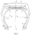
図1に示す建設車両用タイヤは、これ自体は既知であるが、カーカス補強体(1)を有し、該カーカス補強体(1)はスチールで作られた非伸長性金属ケーブルの単一プライからなり、該プライは各ビード内でビードワイヤ(2)に係止されてターンアップ(10)を形成し、該ターンアップの端部は、ほぼ、カーカス補強体(1)の最大軸線方向幅のレベルに位置している。カーカス補強体(1)の半径方向上方には層(20)およびゴム配合物からなる異形部材(21)が載置され、更にこの上には、第1に、ワーキングプライと呼ばれる2つのプライ(31、32)および第2に、いわゆる保護プライ(51、52)が半径方向上方に載置されている。ワーキングプライ(31、32)はスチールからなる非伸長性金属ケーブルで形成され、該金属ケーブルは、これらの各プライ内で互いに平行に配置されかつ一方のプライ(31)から他方のプライ(32)にかけて交差し、周方向に対して15〜45°の間の角度を形成している。ワーキングプライ(31、32)の軸線方向幅は、カーカス補強体(1)の最大軸線方向幅の約60〜80%である。保護プライ(51、52)は一般に、スチールからなる弾性金属ケーブルで形成され、該金属ケーブルは、これらの各プライ(51、52)内で互いに平行に配置されかつ一方のプライ(51)から他方のプライ(52)にかけて交差し、15〜45°の間の角度を形成している。保護プライ(51、52)の幅は、通常、最大幅のワーキングプライより小さい。最後に、半径方向外方のワーキングプライ(32)のケーブルは、通常、半径方向内方の保護プライ(51)のケーブルと交差している。クラウン補強体(3)自体の上にはトレッド(4)が載置され、該トレッド(4)は、2つの側壁(6)を介して2つのビード(7)に結合されている。
【0003】
既知のように、ラジアルタイヤ、より詳しくは大形タイヤのクラウン補強体は大きい変形を受け、この変形が、2つの交差プライの間に長手方向剪断応力および横方向剪断応力を引き起こし(交差プライのケーブルが周方向に対して小さい角度を形成するときには、長手方向剪断応力の方が横方向剪断応力より大きくなる)、同時に、層間剥離応力として、2つのプライの縁部を半径方向に分離させようとする半径方向応力を引き起こす。前記応力は、タイヤの膨張圧力によるものが第1の主要なものであり、これは、カーカス補強体とクラウン補強体との間のいわゆるベルティング圧力がクラウン補強体の周方向伸長を引き起こすことを意味する。次に前記応力は、走行時に路面とタイヤとの間に形成される接触表面との関係でタイヤに発生する荷重によるものであり、最後に、走行時のタイヤのドリフティングによるものである。前記応力は、最短プライの端部に隣接するゴム配合物に割れ目を発生させ、この割れ目はゴム配合物内で拡大し、クラウン補強体の寿命従ってタイヤの寿命に悪影響を与える。
【0004】
軸線方向最大幅をもつワーキングプライより大きい軸線方向幅をもつ少なくとも1つの保護クラウンをクラウン補強体に使用することにより、耐久性に顕著な改善がなされた。
【0005】
フランス国特許第2 421 742号に開示されているように、他の解決方法は、より好ましくは、タイヤのドリフティングの後にワーキングプライの数を増倍化することにより、例えば、一プライから隣接プライにかけて交差(周方向に対して15〜35°の間の角度を形成)している補強要素からなる4つのワーキングプライを用いることにより、および慣用の2つのワーキングプライに使用されている補強要素を4つのワーキングプライ上で分散させ、各ワーキングプライがプライの補強要素に対して垂直に測定して同じ厚さおよび同じ引張り剛性をもつようにすることにより、ワーキングクラウンプライ間に分離を引き起こす応力を分散させることからなる。
【0006】
ワーキングプライの増倍化はその欠点がないわけではなく、特に補強体の中央では、プライの数が、タイヤのクラウンの撓み強度に非常に大きな影響を与える。
【0007】
(発明の開示)
本発明の目的は、幅広保護プライ(単一または複数)を備えたクラウン補強体からなるワーキングプライ間の分離に対する抵抗性を増大させること、従って、補強体の中央でのワーキングプライの数を増大させることなく、建設機械用タイヤのクラウン補強体の耐久性を向上させることにある。
【0008】
本発明によるタイヤは、各ビード内で少なくとも1つのビードワイヤに係止されてターンアップを形成する少なくとも1つのラジアルカーカス補強体を有し、該補強体の半径方向上方には、非伸長性金属補強要素で形成された少なくとも3つのいわゆるワーキングプライからなるクラウン補強体が載置され、前記金属補強要素は各プライ内で互いに平行でかつ一プライから隣接プライにかけて交差し、周方向に対して15〜35°の角度α、α′を形成する構成の重機械用タイヤにおいて、非伸長性金属補強要素で形成されかつ幅L′を有する少なくとも1つのハーフプライが、赤道平面の両側において、少なくとも2つの半径方向に隣接するワーキングプライの縁部の間で半径方向に配置され、ハーフプライの軸線方向外端部および内端部は、それぞれ、少なくともL′/5の大きさに等しい距離だけ、最大幅のワーキングプライの端部より軸線方向外方および最小幅のワーキングプライの端部より軸線方向内方に位置し、ハーフプライの補強要素は周方向に対して角度βを形成し、該角度βは、第1に、絶対値で25°より大きく、第2に、2つのワーキングプライの要素により形成される最大角度より絶対値で5〜15°の間の角度だけ大きいことを特徴とする。
【0009】
好ましくは、ハーフプライは、カーカス補強体に最も近い2つのワーキングプライの間に配置されている。ハーフプライの数が1つであるか2つであるかに拘わらず、各ハーフプライの補強要素は、ハーフプライより半径方向内方でかつカーカス補強体に対して半径方向に最も近いワーキングプライの補強要素と交差しているのが有効である。
【0010】
クラウン補強体のワーキングプライの幅(一般的には不等幅である)は、各ハーフプライより半径方向内方のプライの幅が、ハーフプライより半径方向外方のプライの幅より小さくなるように構成されている。
【0011】
赤道平面XX′の両側に、3つのプライのワーキング補強体の半径方向に隣接する2つのワーキングプライの縁部間に配置された2つのハーフプライが存在する場合に、第2ハーフプライが第1ハーフプライと同じ金属補強要素で形成され、第2ハーフプライの前記補強要素は、好ましくは、第1ハーフプライの補強要素と交差している。
【0012】
このこと自体は既知であるが、ワーキング補強体の半径方向外方には、弾性金属補強要素の2つのプライからなる保護補強体が載置されている。保護プライのうちの一方の保護プライは、好ましくは、ワーキングプライの最大軸線方向幅より大きい軸線方向幅を有する。これに対し、第2保護プライの幅は、ワーキングプライの幅の値の間の値の幅を有する。
【0013】
(発明を実施するための最良の形態)
本発明の特徴は、非制限的態様で実施形態を例示する添付図面を参照して述べる以下の説明からより良く理解されよう。
【0014】
本発明によるタイヤP(そのクラウン補強体が図2に示されている)は、建設車両用タイヤである。主要な寸法のうち、タイヤのH/S形状比は0.80に等しく、ここで、Hは、タイヤがその作動リム上に取り付けられかつその推奨圧力まで膨張されているときの、リム上でのタイヤの高さ、およびSはタイヤの最大軸線方向幅である。
【0015】
タイヤPは、非伸長性金属ケーブルからなる単一プライ(1)を有する。該単一プライ(1)は、各ビード内で少なくとも1つのビードワイヤ(図示せず)に係止されて、ターンアップを形成する。該ターンアップの端部は、ほぼ、カーカス補強体の最大軸線方向幅の直線(該直線は回転軸線に平行である)上に位置する。カーカスプライ(1)には、その中央部内で、ゴム配合物の層(20)が半径方向上方に載置されており、その側方部において、同じゴム配合物で形成された2つの三角異形部材(21)が載置され、該異形部材(21)はカーカス補強体とクラウン補強体との間の子午線方向曲率の差異を補償することができる。実際に、前記層および異形部材の外方には、ワーキングクラウン補強体(3)および保護補強体(5)が配置されている。
【0016】
ワーキング補強体(3)は、第1の主要な3つのワーキングプライ(31)、(32)、(33)を有し、該ワーキングプライは軸線方向に連続しておりかつそれぞれ幅L31、L32、L33を有している。ここに説明する場合には、最小幅プライ(31)は、カーカス補強体(1)に対し半径方向に最も近く配置されている。幅L31、L32、L33は、半径方向内方から半径方向外方にかけて増大している。これらの3つの幅は、それぞれ、0.5S0、0.55S0、0.66S0に等しい。3つのプライ(31)、(32)、(33)は非伸長性金属ケーブルで形成されている。該金属ケーブルは、各プライ内で互いに平行でかつ一プライ(31、32)から隣接プライ(32、33)にかけて交差し、タイヤの周方向に対してそれぞれ角度α1、α2、α3(それぞれ、+18°、−24°、+18°に等しい)を形成している。
【0017】
最小幅プライ(31)の縁部とこれに半径方向に隣接する中間幅のプライ(32)の縁部との半径方向の間には、プライ(31)、(32)、(33)を形成するものと同じ非伸長性金属要素で形成された2つのハーフプライ(34)が配置されている。前記金属要素は、各ハーフプライ(34)内で互いに平行でありかつカーカスプライ(1)に最も近い軸線方向連続プライ(31)の金属要素と交差し、周方向に対して角度βを形成している。この角度βは、角度α1、α2より大きく、−33°に等しい。各ハーフプライ(34)の軸線方向幅L′は0.33S0に等しい。ハーフプライ(34)の軸線方向内端部は、プライ(31)の端部より軸線方向内方の位置であって、赤道平面XX′から次のような軸線方向距離、すなわち、最小幅のワーキングプライ(31)の軸線方向半幅と前記距離との差が0.22L′に等しく、かつハーフプライ(34)の軸線方向内縁部と、ハーフプライ(34)より半径方向内方に位置する最小幅の軸線方向連続プライ(31)とがオーバーラップするような位置にある。ハーフプライ(34)の軸線方向外端部については、該外端部が、最大幅プライ(32)の端部より軸線方向外方にあり、前記距離と最大幅のワーキングプライ(32)の軸線方向半幅との間の距離が0.37L′に等しくなる位置にある。
【0018】
上記ワーキング補強体より半径方向外方にあって、クラウン補強体を完成する保護補強体は、弾性スチールケーブルからなる2つのプライ(51)、(52)で形成されている。破壊荷重に等しい引張り力を受けるとき少なくとも4%の相対伸びを有するケーブルは弾性と呼ばれ、一方、破壊荷重の10%で測定した相対伸びが0.2%以下であるとき、ケーブルは非伸長性であると呼ばれる。前記2つのプライのケーブルは一プライ(51)から隣接プライ(52)にかけて交差し、周方向に対してそれぞれ−24°および+24°に等しい角度を形成する。カーカス補強体に最も近い保護プライ(51)のケーブルは、カーカス補強体から最も遠いワーキングプライ(33)のケーブルと交差している。プライ(51)の軸線方向幅L51は最大幅のワーキングプライ(33)の幅L33よりはるかに大きい。また、プライ(51)の端部はハーフプライ(34)の軸線方向外端部より軸線方向外方に位置しており、保護プライ(51)は全てのワーキングプライおよび挿入されたハーフプライを軸線方向に覆っている。第2保護プライ(52)の幅L52は、2つの最大幅ワーキングプライ(32)、(33)の幅L32、L33の和の1/2にほぼ等しい。
【0019】
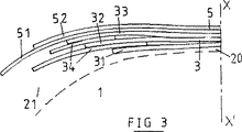
図3は、ワーキングプライ(31)と(32)との間およびワーキングプライ(32)と(33)との間に配置された2つのハーフプライ(34)を有するクラウン補強体の実施形態を示す。ワーキングプライ(31、32、33)は全ての点で前述のワーキングプライと同じである。第1ハーフプライ(34)についても、図2のハーフプライ(34)と同じことが適用される。ワーキングプライ(32)と(33)との間の第2ハーフプライ(34)について説明すると、該第2ハーフプライ(34)は、第1ハーフプライのケーブルと同じケーブルで形成されており、該ケーブルは、周方向に対して33°の角度βを形成し、かつ第1ハーフプライ(34)のケーブルと交差している。第2ハーフプライの軸線方向幅は前述の原理に従がって定められ、また、それ自体は既知であるが、プライの両端部が同じ平行平面内にないように用心する。
【図面の簡単な説明】
【図1】 従来技術による建設車両用タイヤのクラウン補強体の子午線方向断面図である。
【図2】 本発明によるクラウン補強体の第1実施形態を示す子午線方向断面図である。
【図3】 本発明によるクラウン補強体の第2実施形態を示す子午線方向断面図である。[0001]
(Technical field)
The present invention relates to a tire with a radial carcass reinforcement intended to be mounted on a heavy vehicle such as a transport vehicle or construction machine, and more particularly to a crown reinforcement for such a tire.
[0002]
(Background technology)
The construction vehicle tire shown in FIG. 1, which is known per se, has a carcass reinforcement (1), which is a single ply of non-extensible metal cable made of steel. The plies are locked to bead wires (2) within each bead to form a turn-up (10), the end of the turn-up being approximately the maximum axial width of the carcass reinforcement (1). Located in the level. A deformed member (21) made of a layer (20) and a rubber compound is placed above the carcass reinforcing body (1) in the radial direction, and on top of this, firstly, two plies called working plies ( 31, 32) and secondly so-called protective plies (51, 52) are placed radially upward. The working plies (31, 32) are formed of non-extensible metal cables made of steel, which are arranged parallel to each other in each of these plies and from one ply (31) to the other ply (32) To form an angle of 15 to 45 ° with respect to the circumferential direction. The axial width of the working plies (31, 32) is about 60 to 80% of the maximum axial width of the carcass reinforcing body (1). The protective plies (51, 52) are generally formed of elastic metal cables made of steel, which are arranged parallel to each other in each of these plies (51, 52) and from one ply (51) to the other. Crossing over the ply (52), forming an angle between 15 and 45 °. The width of the protective ply (51, 52) is usually smaller than the maximum working ply. Finally, the radially outer working ply (32) cable typically intersects the radially inner protective ply (51) cable. A tread (4) is placed on the crown reinforcement (3) itself, and the tread (4) is coupled to two beads (7) via two side walls (6).
[0003]
As is known, radial tires, and more particularly large tire crown reinforcements, are subject to large deformations which cause longitudinal and lateral shear stresses between the two cross plies (cross plys). When the cable forms a small angle with respect to the circumferential direction, the longitudinal shear stress will be greater than the transverse shear stress), while at the same time letting the edges of the two plies radially separate as delamination stress Cause radial stress. The stress is primarily due to the tire inflation pressure, which means that the so-called belting pressure between the carcass reinforcement and the crown reinforcement causes the crown reinforcement to elongate in the circumferential direction. means. Next, the stress is due to the load generated in the tire due to the relationship between the road surface and the contact surface formed between the tire during traveling, and finally due to the drifting of the tire during traveling. The stress causes a crack in the rubber compound adjacent to the end of the shortest ply, and the crack expands in the rubber compound and adversely affects the life of the crown reinforcement and thus the life of the tire.
[0004]
The use of at least one protective crown having a larger axial width than the working ply having the maximum axial width in the crown reinforcement has resulted in a significant improvement in durability.
[0005]
As disclosed in French Patent No. 2 421 742, another solution is more preferably by multiplying the number of working plies after tire drifting, for example from one ply to adjacent By using four working plies consisting of reinforcing elements that intersect (form an angle between 15 and 35 ° with respect to the circumferential direction) over the ply, and the reinforcing elements used in two conventional working plies Are distributed over the four working plies, each working ply being measured perpendicular to the reinforcement element of the ply and having the same thickness and the same tensile stiffness, thereby causing a separation between the working crown plies. Consists of dispersing.
[0006]
The multiplication of the working ply is not without its disadvantages, and the number of plies has a great influence on the flexural strength of the tire crown, particularly in the center of the reinforcement.
[0007]
(Disclosure of the Invention)
The object of the present invention is to increase the resistance to separation between working plies consisting of crown reinforcements with wide protective ply (s), and thus increase the number of working plies in the middle of the reinforcement It is to improve the durability of the crown reinforcement body of the tire for construction machinery without causing it.
[0008]
The tire according to the present invention has at least one radial carcass reinforcement that is locked to at least one bead wire within each bead to form a turn-up, and in the radial direction above the reinforcement is a non-extensible metal reinforcement. A crown reinforcement consisting of at least three so-called working plies formed of elements is mounted, the metal reinforcement elements being parallel to each other in each ply and intersecting from one ply to an adjacent ply, In a heavy machine tire configured to form an angle α, α ′ of 35 °, at least one half-ply formed of a non-extensible metal reinforcing element and having a width L ′ is at least two on either side of the equator plane. It is arranged radially between the edges of the working ply adjacent in the radial direction, and the axially outer end and inner end of the half ply are Reinforcement of the half ply, which is located axially outward from the end of the largest working ply and axially inward from the end of the smallest working ply by a distance at least equal to the size of L '/ 5 The elements form an angle β with respect to the circumferential direction, which is firstly greater than 25 ° in absolute value and secondly in absolute value from the maximum angle formed by the elements of the two working plies. It is characterized by being larger by an angle between 5 and 15 °.
[0009]
Preferably, the half ply is disposed between the two working plies closest to the carcass reinforcement. Regardless of whether the number of half plies is one or two, the reinforcing element of each half ply is the working ply that is radially inward of the half ply and closest to the carcass reinforcement in the radial direction. It is effective to cross the reinforcing element.
[0010]
The width of the working ply (generally unequal width) of the crown reinforcement is such that the width of the ply radially inward from each half ply is smaller than the width of the ply radially outward from the half ply. It is configured.
[0011]
If there are two half plies located between the edges of two working plies radially adjacent to the working reinforcement of the three plies on either side of the equator plane XX ′, the second half ply is the first Formed from the same metal reinforcement element as the half ply, the reinforcement element of the second half ply preferably intersects the reinforcement element of the first half ply.
[0012]
Although this is known per se, a protective reinforcing body composed of two plies of elastic metal reinforcing elements is placed radially outward of the working reinforcing body. One of the protective plies preferably has an axial width that is greater than the maximum axial width of the working ply. In contrast, the width of the second protective ply has a value width between the values of the working ply width.
[0013]
(Best Mode for Carrying Out the Invention)
The features of the present invention will be better understood from the following description with reference to the accompanying drawings, which illustrate the embodiments in a non-limiting manner.
[0014]
The tire P according to the present invention (its crown reinforcement is shown in FIG. 2) is a tire for construction vehicles. Of the major dimensions, the H / S shape ratio of the tire is equal to 0.80, where H is on the rim when the tire is mounted on its working rim and inflated to its recommended pressure. The tire height and S are the maximum axial width of the tire.
[0015]
The tire P has a single ply (1) made of a non-extensible metal cable. The single ply (1) is locked to at least one bead wire (not shown) within each bead to form a turn-up. The end of the turn-up is substantially located on a straight line having a maximum axial width of the carcass reinforcement (the straight line is parallel to the rotation axis). The carcass ply (1) has a rubber compound layer (20) placed radially upward in its central part, and two triangular variants formed of the same rubber compound in its side part. A member (21) is placed, which can compensate for the difference in meridional curvature between the carcass reinforcement and the crown reinforcement. Actually, a working crown reinforcing body (3) and a protective reinforcing body (5) are arranged outside the layer and the deformed member.
[0016]
The working reinforcement (3) has three first main working plies (31), (32), (33), which are continuous in the axial direction and have widths L 31 , L, respectively. and a 32, L 33. In the case described here, the minimum width ply (31) is arranged closest to the carcass reinforcing body (1) in the radial direction. The widths L 31 , L 32 , and L 33 increase from the radially inner side to the radially outer side. These three widths are equal to 0.5S 0 , 0.55S 0 , and 0.66S 0 , respectively. The three plies (31), (32), (33) are formed of non-extensible metal cables. The metal cables are parallel to each other in each ply and intersect from one ply (31, 32) to the adjacent ply (32, 33), and have angles α 1 , α 2 , α 3 ( Are equal to + 18 °, −24 °, and + 18 °, respectively.
[0017]
Plies (31), (32), and (33) are formed between the edge of the minimum width ply (31) and the edge of the intermediate width ply (32) that is radially adjacent thereto. Two half plies (34) made of the same non-extensible metal element as are to be placed are arranged. Said metal elements are parallel to each other in each half ply (34) and intersect the metal elements of the axially continuous ply (31) closest to the carcass ply (1), forming an angle β with respect to the circumferential direction. ing. This angle β is larger than the angles α 1 and α 2 and equal to −33 °. The axial width L ′ of each half ply (34) is equal to 0.33S 0 . The axially inner end of the half ply (34) is located axially inward from the end of the ply (31), and the following axial distance from the equator plane XX ', that is, the minimum working width The difference between the axial half width of the ply (31) and the distance is equal to 0.22L ', and the minimum inner width of the half ply (34) is located radially inward from the inner edge of the half ply (34). It is in the position which overlaps with an axial direction continuous ply (31). As for the axially outer end of the half ply (34), the outer end is axially outward from the end of the maximum width ply (32), and the axis of the distance and maximum width of the working ply (32) The distance between the direction half widths is equal to 0.37L '.
[0018]
The protective reinforcing body that is radially outward from the working reinforcing body and completes the crown reinforcing body is formed of two plies (51) and (52) made of an elastic steel cable. A cable with a relative elongation of at least 4% when subjected to a tensile force equal to the breaking load is called elastic, whereas a cable is non-stretching when the relative elongation measured at 10% of the breaking load is less than 0.2% Called sex. The two-ply cables intersect from one ply (51) to an adjacent ply (52), forming an angle equal to −24 ° and + 24 °, respectively, with respect to the circumferential direction. The cable of the protective ply (51) closest to the carcass reinforcement crosses the cable of the working ply (33) furthest from the carcass reinforcement. The axial width L 51 of the ply (51) is much larger than the width L 33 of the maximum working ply (33). The end of the ply (51) is positioned axially outward from the outer end of the half ply (34) in the axial direction, and the protective ply (51) is connected to all the working plies and the inserted half ply. Covering in the direction. The width L 52 of the second protective ply (52) is approximately equal to ½ of the sum of the widths L 32 and L 33 of the two maximum width working plies (32) and (33).
[0019]
FIG. 3 shows an embodiment of a crown reinforcement having two half plies (34) disposed between the working plies (31) and (32) and between the working plies (32) and (33). . The working ply (31, 32, 33) is the same as the working ply described above in all respects. The same applies to the first half ply (34) as the half ply (34) of FIG. The second half ply (34) between the working plies (32) and (33) will be described. The second half ply (34) is formed of the same cable as the cable of the first half ply, The cable forms an angle β of 33 ° with respect to the circumferential direction and intersects the cable of the first half-ply (34). The axial width of the second half ply is determined according to the principle described above and is known per se, but care is taken that the ends of the ply are not in the same parallel plane.
[Brief description of the drawings]
FIG. 1 is a meridional direction sectional view of a crown reinforcement body of a construction vehicle tire according to the prior art.
FIG. 2 is a meridian sectional view showing a crown reinforcing body according to a first embodiment of the present invention.
FIG. 3 is a meridian sectional view showing a second embodiment of a crown reinforcement according to the present invention.
Claims (7)
Applications Claiming Priority (3)
| Application Number | Priority Date | Filing Date | Title |
|---|---|---|---|
| FR99/03416 | 1999-03-17 | ||
| FR9903416A FR2791001B1 (en) | 1999-03-17 | 1999-03-17 | TIRE FOR HEAVY EQUIPMENT |
| PCT/EP2000/001669 WO2000054992A1 (en) | 1999-03-17 | 2000-02-28 | Tyre for heavy vehicle |
Publications (3)
| Publication Number | Publication Date |
|---|---|
| JP2002539022A JP2002539022A (en) | 2002-11-19 |
| JP2002539022A5 JP2002539022A5 (en) | 2007-04-12 |
| JP4659221B2 true JP4659221B2 (en) | 2011-03-30 |
Family
ID=9543383
Family Applications (1)
| Application Number | Title | Priority Date | Filing Date |
|---|---|---|---|
| JP2000605044A Expired - Fee Related JP4659221B2 (en) | 1999-03-17 | 2000-02-28 | Heavy machinery tires |
Country Status (14)
| Country | Link |
|---|---|
| US (1) | US6598639B2 (en) |
| EP (1) | EP1163119B1 (en) |
| JP (1) | JP4659221B2 (en) |
| CN (1) | CN1214934C (en) |
| AU (1) | AU760462B2 (en) |
| BR (1) | BR0009002A (en) |
| CA (1) | CA2361904C (en) |
| DE (1) | DE60001718T2 (en) |
| ES (1) | ES2190957T3 (en) |
| FR (1) | FR2791001B1 (en) |
| ID (1) | ID30443A (en) |
| RU (1) | RU2235649C2 (en) |
| WO (1) | WO2000054992A1 (en) |
| ZA (1) | ZA200001294B (en) |
Families Citing this family (13)
| Publication number | Priority date | Publication date | Assignee | Title |
|---|---|---|---|---|
| FR2824295A1 (en) * | 2001-05-03 | 2002-11-08 | Michelin Soc Tech | SUMMIT FRAME FOR CIVIL ENGINEERED TIRES |
| FR2827221A1 (en) | 2001-07-16 | 2003-01-17 | Michelin Soc Tech | Pneumatic tire for heavy vehicle has additional crown reinforcing half layers on either side of median circumferential plane |
| FR2845640A1 (en) * | 2002-10-10 | 2004-04-16 | Michelin Soc Tech | Pneumatic tire for heavy vehicle or machine has crown reinforcement extended on either side of median plane by at least three half-layers |
| FR2857619B1 (en) * | 2003-07-18 | 2005-08-19 | Michelin Soc Tech | PNEUMATIC FOR HEAVY VEHICLES |
| US7086440B2 (en) * | 2003-11-14 | 2006-08-08 | The Goodyear Tire & Rubber Company | Pneumatic tire with annular reinforcing strip layer |
| JP4747773B2 (en) | 2005-10-11 | 2011-08-17 | 横浜ゴム株式会社 | Pneumatic tire |
| CN100411891C (en) * | 2006-03-06 | 2008-08-20 | 江苏通用科技股份有限公司 | Light truck tyre with steel wire and meridian line structure |
| FR2909587B1 (en) * | 2006-12-06 | 2009-01-16 | Michelin Soc Tech | PNEUMATIC FOR HEAVY VEHICLE. |
| JP5759134B2 (en) * | 2010-09-28 | 2015-08-05 | 株式会社ブリヂストン | Pneumatic tire |
| KR101212228B1 (en) | 2010-12-06 | 2012-12-13 | 한국타이어월드와이드 주식회사 | Truck and bus radial tire |
| DE102012112452A1 (en) | 2012-12-17 | 2014-06-18 | Continental Reifen Deutschland Gmbh | Vehicle tires |
| CN104527330A (en) * | 2014-12-09 | 2015-04-22 | 杭州朝阳橡胶有限公司 | Single-layer high elongation steel wire reinforced belt ply structure and design method thereof |
| EP3746313B1 (en) * | 2018-01-30 | 2022-03-23 | Compagnie Generale Des Etablissements Michelin | Tyre comprising three working layers |
Citations (9)
| Publication number | Priority date | Publication date | Assignee | Title |
|---|---|---|---|---|
| DE3327670A1 (en) * | 1983-07-30 | 1985-02-07 | Continental Gummi-Werke Ag, 3000 Hannover | Pneumatic tyre for a vehicle |
| JPH02200502A (en) * | 1989-01-30 | 1990-08-08 | Yokohama Rubber Co Ltd:The | Pneumatic tire and manufacturing method therefor |
| JPH0367704A (en) * | 1989-08-07 | 1991-03-22 | Bridgestone Corp | Heavy duty pneumatic radial tire |
| JPH03191210A (en) * | 1989-12-19 | 1991-08-21 | Universal Toreedengu Kk | Stability leg for combustion device |
| JPH03231003A (en) * | 1990-02-05 | 1991-10-15 | Bridgestone Corp | Pneumatic radial tire for bicycle |
| JPH04154404A (en) * | 1990-10-18 | 1992-05-27 | Toyo Tire & Rubber Co Ltd | Radial tire having belt reinforcement layer |
| JPH0524413A (en) * | 1991-07-25 | 1993-02-02 | Bridgestone Corp | Pneumatic radial tire for heavy load |
| JPH0840012A (en) * | 1994-04-28 | 1996-02-13 | Sumitomo Rubber Ind Ltd | Radial tire for heavy load |
| JPH10329511A (en) * | 1997-05-29 | 1998-12-15 | Toyo Tire & Rubber Co Ltd | Pneumatic radial tyre |
Family Cites Families (8)
| Publication number | Priority date | Publication date | Assignee | Title |
|---|---|---|---|---|
| DE1605639A1 (en) * | 1967-11-30 | 1970-01-29 | Continental Gummi Werke Ag | Pneumatic vehicle tires |
| JPS5445004A (en) * | 1977-09-16 | 1979-04-10 | Bridgestone Corp | Pneumatic radial tire that has durability at high speed |
| FR2421742A1 (en) | 1978-04-07 | 1979-11-02 | Michelin & Cie | RADIAL CASING PNEUMATIC |
| JPS55132306A (en) * | 1979-03-28 | 1980-10-15 | Sumitomo Rubber Ind Ltd | Radial tire |
| JPS5977906A (en) * | 1982-10-27 | 1984-05-04 | Sumitomo Rubber Ind Ltd | Radial tire for heavy vehicle |
| JPH0199703U (en) * | 1987-12-25 | 1989-07-04 | ||
| DE4240278A1 (en) * | 1992-12-01 | 1994-06-09 | Uniroyal Englebert Gmbh | Pneumatic vehicle tires with asymmetrical belt properties |
| US5830295A (en) | 1997-02-14 | 1998-11-03 | The Goodyear Tire & Rubber Company | Pneumatic tire with belt structure including reinforced gum strips |
-
1999
- 1999-03-17 FR FR9903416A patent/FR2791001B1/en not_active Expired - Fee Related
-
2000
- 2000-02-28 BR BR0009002-6A patent/BR0009002A/en not_active IP Right Cessation
- 2000-02-28 WO PCT/EP2000/001669 patent/WO2000054992A1/en active IP Right Grant
- 2000-02-28 CN CNB008045968A patent/CN1214934C/en not_active Expired - Fee Related
- 2000-02-28 EP EP00915156A patent/EP1163119B1/en not_active Expired - Lifetime
- 2000-02-28 RU RU2001128065/11A patent/RU2235649C2/en not_active IP Right Cessation
- 2000-02-28 ES ES00915156T patent/ES2190957T3/en not_active Expired - Lifetime
- 2000-02-28 CA CA002361904A patent/CA2361904C/en not_active Expired - Fee Related
- 2000-02-28 DE DE60001718T patent/DE60001718T2/en not_active Expired - Lifetime
- 2000-02-28 ID IDW00200102025A patent/ID30443A/en unknown
- 2000-02-28 JP JP2000605044A patent/JP4659221B2/en not_active Expired - Fee Related
- 2000-02-28 AU AU36567/00A patent/AU760462B2/en not_active Ceased
- 2000-03-14 ZA ZA200001294A patent/ZA200001294B/en unknown
-
2001
- 2001-09-17 US US09/953,647 patent/US6598639B2/en not_active Expired - Lifetime
Patent Citations (9)
| Publication number | Priority date | Publication date | Assignee | Title |
|---|---|---|---|---|
| DE3327670A1 (en) * | 1983-07-30 | 1985-02-07 | Continental Gummi-Werke Ag, 3000 Hannover | Pneumatic tyre for a vehicle |
| JPH02200502A (en) * | 1989-01-30 | 1990-08-08 | Yokohama Rubber Co Ltd:The | Pneumatic tire and manufacturing method therefor |
| JPH0367704A (en) * | 1989-08-07 | 1991-03-22 | Bridgestone Corp | Heavy duty pneumatic radial tire |
| JPH03191210A (en) * | 1989-12-19 | 1991-08-21 | Universal Toreedengu Kk | Stability leg for combustion device |
| JPH03231003A (en) * | 1990-02-05 | 1991-10-15 | Bridgestone Corp | Pneumatic radial tire for bicycle |
| JPH04154404A (en) * | 1990-10-18 | 1992-05-27 | Toyo Tire & Rubber Co Ltd | Radial tire having belt reinforcement layer |
| JPH0524413A (en) * | 1991-07-25 | 1993-02-02 | Bridgestone Corp | Pneumatic radial tire for heavy load |
| JPH0840012A (en) * | 1994-04-28 | 1996-02-13 | Sumitomo Rubber Ind Ltd | Radial tire for heavy load |
| JPH10329511A (en) * | 1997-05-29 | 1998-12-15 | Toyo Tire & Rubber Co Ltd | Pneumatic radial tyre |
Also Published As
| Publication number | Publication date |
|---|---|
| BR0009002A (en) | 2002-01-02 |
| ZA200001294B (en) | 2000-10-11 |
| JP2002539022A (en) | 2002-11-19 |
| FR2791001B1 (en) | 2001-05-04 |
| ES2190957T3 (en) | 2003-09-01 |
| CN1342117A (en) | 2002-03-27 |
| DE60001718T2 (en) | 2003-12-18 |
| AU3656700A (en) | 2000-10-04 |
| US6598639B2 (en) | 2003-07-29 |
| US20020007894A1 (en) | 2002-01-24 |
| ID30443A (en) | 2001-12-06 |
| AU760462B2 (en) | 2003-05-15 |
| EP1163119B1 (en) | 2003-03-19 |
| WO2000054992A1 (en) | 2000-09-21 |
| DE60001718D1 (en) | 2003-04-24 |
| RU2235649C2 (en) | 2004-09-10 |
| FR2791001A1 (en) | 2000-09-22 |
| CN1214934C (en) | 2005-08-17 |
| CA2361904A1 (en) | 2000-09-21 |
| CA2361904C (en) | 2008-04-22 |
| EP1163119A1 (en) | 2001-12-19 |
Similar Documents
| Publication | Publication Date | Title |
|---|---|---|
| JP4354114B2 (en) | Crown reinforcement for heavy vehicle tires | |
| JP4689593B2 (en) | Crown reinforcement for radial tires | |
| JP4216339B2 (en) | Crown reinforcement for “heavy vehicle” tires with a shape ratio ≦ 0.60 | |
| JP5259605B2 (en) | Heavy vehicle tires | |
| JP4133338B2 (en) | Pneumatic tire | |
| EP2246202B1 (en) | Floating two-ply tire | |
| JP4659221B2 (en) | Heavy machinery tires | |
| JP4342725B2 (en) | Tire with triangular crown reinforcement | |
| JP5657646B2 (en) | Reinforcing material comprising two reinforcing materials and tire having such a reinforcing material | |
| JP4383662B2 (en) | Tire with triangular crown reinforcement | |
| JP4286453B2 (en) | Tire crown reinforcement | |
| JP2002514538A (en) | Radial tire crown reinforcement | |
| JP4984662B2 (en) | Pneumatic tire | |
| JP4672644B2 (en) | Crown reinforcement for radial tires | |
| CN109476189B (en) | Tire with reduced weight bead area | |
| JP5474935B2 (en) | Reinforced tires for heavy-duty vehicles | |
| JP4485194B2 (en) | Heavy vehicle tires | |
| JP2001505509A (en) | Tire crown reinforcement | |
| JP6507029B2 (en) | Pneumatic tire | |
| JP5164453B2 (en) | Pneumatic tire | |
| JP4511355B2 (en) | Heavy machinery tires | |
| JPH02267012A (en) | Pneumatic radial tire for heavy load | |
| JP5323716B2 (en) | Heavy vehicle tires | |
| JP2006502040A5 (en) | ||
| JP4580559B2 (en) | Tire bead |
Legal Events
| Date | Code | Title | Description |
|---|---|---|---|
| A521 | Written amendment |
Free format text: JAPANESE INTERMEDIATE CODE: A523 Effective date: 20070223 |
|
| A621 | Written request for application examination |
Free format text: JAPANESE INTERMEDIATE CODE: A621 Effective date: 20070223 |
|
| A977 | Report on retrieval |
Free format text: JAPANESE INTERMEDIATE CODE: A971007 Effective date: 20100112 |
|
| A131 | Notification of reasons for refusal |
Free format text: JAPANESE INTERMEDIATE CODE: A131 Effective date: 20100114 |
|
| A601 | Written request for extension of time |
Free format text: JAPANESE INTERMEDIATE CODE: A601 Effective date: 20100414 |
|
| A602 | Written permission of extension of time |
Free format text: JAPANESE INTERMEDIATE CODE: A602 Effective date: 20100421 |
|
| A521 | Written amendment |
Free format text: JAPANESE INTERMEDIATE CODE: A523 Effective date: 20100713 |
|
| A131 | Notification of reasons for refusal |
Free format text: JAPANESE INTERMEDIATE CODE: A131 Effective date: 20100805 |
|
| A521 | Written amendment |
Free format text: JAPANESE INTERMEDIATE CODE: A523 Effective date: 20101102 |
|
| TRDD | Decision of grant or rejection written | ||
| A01 | Written decision to grant a patent or to grant a registration (utility model) |
Free format text: JAPANESE INTERMEDIATE CODE: A01 Effective date: 20101125 |
|
| A01 | Written decision to grant a patent or to grant a registration (utility model) |
Free format text: JAPANESE INTERMEDIATE CODE: A01 |
|
| A61 | First payment of annual fees (during grant procedure) |
Free format text: JAPANESE INTERMEDIATE CODE: A61 Effective date: 20101227 |
|
| FPAY | Renewal fee payment (event date is renewal date of database) |
Free format text: PAYMENT UNTIL: 20140107 Year of fee payment: 3 |
|
| R150 | Certificate of patent or registration of utility model |
Ref document number: 4659221 Country of ref document: JP Free format text: JAPANESE INTERMEDIATE CODE: R150 Free format text: JAPANESE INTERMEDIATE CODE: R150 |
|
| R250 | Receipt of annual fees |
Free format text: JAPANESE INTERMEDIATE CODE: R250 |
|
| R250 | Receipt of annual fees |
Free format text: JAPANESE INTERMEDIATE CODE: R250 |
|
| R250 | Receipt of annual fees |
Free format text: JAPANESE INTERMEDIATE CODE: R250 |
|
| R250 | Receipt of annual fees |
Free format text: JAPANESE INTERMEDIATE CODE: R250 |
|
| R250 | Receipt of annual fees |
Free format text: JAPANESE INTERMEDIATE CODE: R250 |
|
| LAPS | Cancellation because of no payment of annual fees |