JP4657602B2 - Virtual PCI device apparatus and method - Google Patents
Virtual PCI device apparatus and method Download PDFInfo
- Publication number
- JP4657602B2 JP4657602B2 JP2003509332A JP2003509332A JP4657602B2 JP 4657602 B2 JP4657602 B2 JP 4657602B2 JP 2003509332 A JP2003509332 A JP 2003509332A JP 2003509332 A JP2003509332 A JP 2003509332A JP 4657602 B2 JP4657602 B2 JP 4657602B2
- Authority
- JP
- Japan
- Prior art keywords
- pci
- bus
- host
- host bus
- cycle
- Prior art date
- Legal status (The legal status is an assumption and is not a legal conclusion. Google has not performed a legal analysis and makes no representation as to the accuracy of the status listed.)
- Expired - Fee Related
Links
Images


Classifications
-
- G—PHYSICS
- G06—COMPUTING; CALCULATING OR COUNTING
- G06F—ELECTRIC DIGITAL DATA PROCESSING
- G06F13/00—Interconnection of, or transfer of information or other signals between, memories, input/output devices or central processing units
- G06F13/10—Program control for peripheral devices
-
- G—PHYSICS
- G06—COMPUTING; CALCULATING OR COUNTING
- G06F—ELECTRIC DIGITAL DATA PROCESSING
- G06F13/00—Interconnection of, or transfer of information or other signals between, memories, input/output devices or central processing units
- G06F13/10—Program control for peripheral devices
- G06F13/105—Program control for peripheral devices where the programme performs an input/output emulation function
Description
[発明の背景]
発明の技術分野
本発明は、一般にコンピュータに関する。より詳細には、本発明は、データ転送バスに関する。
従来技術の説明
PCI−SIG(Peripheral Component Interconnect−Special Interest Group)により公開されたPCIローカルバス仕様(PCI Local Bus Specification)Rev.2.2とPCI−PCIブリッジアーキテクチャ仕様(PCI to PCI Bridge Architecture Specification)Rev.1.1は、ネットワークコントローラ、大容量記憶装置コントローラ、ディスプレイコントローラ、マルチメディア装置、通信装置及び他の装置をシステムに統合するためのPCIバスプロトコルを規定するものである。PCIバスプロトコルは、ソフトウェアがPCIデバイスと協調するための電気特性及び方法に関する仕様を含み、一般的に、ホストバス、プロセッサまたはメモリのような他のシステム構成要素に利用されるプロトコルとは独立な方法により周辺デバイスの統合を行う。
[Background of the invention]
TECHNICAL FIELD OF THE INVENTION The present invention relates generally to computers. More particularly, the present invention relates to a data transfer bus.
Description of Prior Art PCI Local Bus Specification (PCI Local Bus Specification) Rev. published by PCI-SIG (Peripheral Component Interconnect-Special Interest Group). 2.2 and PCI-PCI Bridge Architecture Specification Rev. 1.1 defines a PCI bus protocol for integrating network controllers, mass storage controllers, display controllers, multimedia devices, communication devices and other devices into the system. The PCI bus protocol contains specifications regarding the electrical characteristics and methods for software to cooperate with PCI devices and is generally independent of the protocol used for other system components such as the host bus, processor or memory. Peripheral devices are integrated by the method.
PCIプロトコルは、コンピュータプログラムによるPCIデバイスへの直接的なアクセス及びPCIデバイスの設定を可能にする「フック(hook)」を提供する。このフックには、各PCIデバイスに関連付けされた256個の8ビット設定レジスタにアクセスするための設定アドレス空間が含まる。これにより、ユーザによる操作なく、システムアドレスマップの構築のため、システムにインストールされている各PCIデバイスの選択的な検出、ベンダーとデバイスタイプの特定、各PCIデバイスのシステムリソース要件についての判断、システムアドレス空間内での各デバイスの再配置、バインディング(binding)の中断、インストール、設定及び起動を、コンピュータプログラムは実行することができる。設定レジスタには、所定のヘッダー領域とデバイス依存領域が含まれるが、各領域の必要性かつ関連性のあるレジスタのみが実現される必要がある。PCI−PCIブリッジは、レンジバス番号を当該PCI−PCIブリッジから後ろのPCIバスに割り当てるコンピュータプログラムにアクセス可能である設定レジスタを有するPCI装置である。 The PCI protocol provides a “hook” that allows a computer program to directly access and configure a PCI device. This hook includes a setting address space for accessing 256 8-bit setting registers associated with each PCI device. This enables the selective detection of each PCI device installed in the system, the identification of the vendor and device type, the determination of the system resource requirements of each PCI device, the system, in order to construct a system address map without user operation The computer program can execute rearrangement of each device in the address space, suspension of binding, installation, setting, and activation. The setting register includes a predetermined header area and a device-dependent area, but only the necessary and relevant registers for each area need to be realized. The PCI-PCI bridge is a PCI device having a setting register that can access a computer program that assigns a range bus number to a PCI bus behind the PCI-PCI bridge.
設定空間は、ホストコンピュータにおいて実行されるコンピュータプログラムにより始動される設定サイクルを介しアクセスされる。PCIプロトコルは、異なる2つの機構の一方を通じ設定サイクルのルーティングが実行されると予想する。これらの機構で、
ホスト−PCIブリッジは、ターゲットPCIデバイスにより受信される当該PCIデバイスが現在の設定サイクルでのターゲットであると通知するPCIバス信号に関し、ソフトウェアコマンドをターゲットPCIバスにおける1つの設定サイクルに解釈する。
The configuration space is accessed through a configuration cycle that is initiated by a computer program running on the host computer. The PCI protocol expects configuration cycle routing to be performed through one of two different mechanisms. With these mechanisms,
The host-PCI bridge interprets the software command into one configuration cycle on the target PCI bus with respect to the PCI bus signal notifying that the PCI device received by the target PCI device is the target in the current configuration cycle.
あるシステムにおけるPCIデバイスの検出及び初期化は、設定空間を利用し、デバイスに依存しないプログラムにより実行される。プログラムは、PCIバス0における各スロットに割り当てられた設定空間をポーリングし、バス0上のPCIデバイス及びPCI−PCIブリッジを検出する。当該プログラムは、設定レジスタに書き込むことにより、検出されたPCI−PCIブリッジのそれぞれに一意的なバス番号を割り当て、割り当てられたバスそれぞれにおける各スロットをポーリングし、PCIデバイス及びPCI−PCIブリッジを検出するようにしてもよい。検出されたPCIバスそれぞれの各スロットがポーリングされ、すべてのPCIデバイスが検出されるまで、上記処理は続けられる。システムにインストールされていると検出された各PCIデバイスに対し、リソース要件を判断するため、デバイスの設定レジスタが読み出される。システム及び様々なPCIデバイス間のコンフリクトを回避するようシステムアドレスマップが構成され、各PCIデバイスの適切な設定レジスタに書き込むことにより、システムリソースが各PCIデバイスに割り当てられるようにしてもよい。さらに、自己診断テストや他の初期化処理をサポートするデバイス上に自己診断テストが呼び出され、各PCIデバイスに対し、インストールと設定がユーザ操作により、あるいはユーザ操作なしに実行されるようにしてもよい。 Detection and initialization of a PCI device in a certain system is executed by a device-independent program using a setting space. The program polls the setting space allocated to each slot in the PCI bus 0 and detects a PCI device and a PCI-PCI bridge on the bus 0. The program assigns a unique bus number to each detected PCI-PCI bridge by writing to the configuration register, polls each slot in each assigned bus, and detects PCI devices and PCI-PCI bridges You may make it do. Each slot of each detected PCI bus is polled and the process continues until all PCI devices are detected. For each PCI device detected to be installed in the system, the device configuration register is read to determine the resource requirements. A system address map may be configured to avoid conflicts between the system and various PCI devices, and system resources may be allocated to each PCI device by writing to the appropriate configuration register for each PCI device. In addition, the self-diagnostic test may be called on a device that supports the self-diagnostic test or other initialization processing, and installation and setting may be executed for each PCI device by user operation or without user operation. Good.
PCIプロトコルに厳格に従うことによる短所として、データ転送速度、データパス幅、待ち時間(latency)及び帯域幅を限定してしまい、PCIデバイスのパフォーマンスの上限を設けてしまうという問題点がある。また、ホスト−PCIブリッジに特有の遅延と、共有PCIバス上の複数のPCIデバイスに特有の帯域幅に関する制約により、パフォーマンスは制限される。現在の傾向としては、より高いパフォーマンスのプロセッサ、メモリ及びホストバスを求めるというものであり、そこでは、効率的に接続されたデバイスが、実際のPCIバスへの接続を通じてよりも、より低い待ち時間、より高いスループット及びより良いシステム全体のパフォーマンスのようなパフォーマンス効果を達成することができる。 Disadvantages of strictly following the PCI protocol include the problem of limiting the data transfer rate, data path width, latency, and bandwidth, and setting an upper limit for PCI device performance. In addition, performance is limited by delays specific to host-PCI bridges and bandwidth limitations specific to multiple PCI devices on a shared PCI bus. The current trend is for higher performance processors, memory and host buses, where efficiently connected devices have lower latency than through connections to the actual PCI bus. Performance effects such as higher throughput and better overall system performance can be achieved.
PCIブリッジ仕様により要求されているプラグ・アンド・プレイ(登録商標)リソース配分プログラムは、典型的には、あるPCIバスに割り当てられたアドレス空間が当該PCIバスより後方のPCIバスに割り当てられるアドレス空間を含むことを予期する。従って、PCIプロトコルへの完全な準拠は、PCIデバイスをホスト−PCIブリッジのホストプロセッサ側に配置することをより困難にし、この場合、PCIデバイスは、(恐らく互換性に関する理由のため)物理的なPCIバスに割り当てられたアドレス空間の一部であるアドレス空間を要求する。
[詳細な説明]
ネットワークコントローラ、大容量記憶装置コントローラ、ディスプレイコントローラ、マルチメディアデバイス、通信デバイス及びその他のデバイスのホストバスプロセッサへの統合、及びデバイスのプロセッサホストバスへの効率的な接続のための実施例が提供される。PCIプロトコルの選択された特徴が順守され、PCIに準拠したデバイスにのみ利用可能なデバイスのためのソフトウェアサポートを可能にする。本発明は、いくつかのシステムにおいて、システムパフォーマンスの向上、デバイスパフォーマンスの向上、システム内のすべてのデバイスのよりシンプルな初期化及び設定、システムリソース配分処理における頑健性の向上、全体コストの低下、及び物理的なボード/チップスペースの減少、さらに、物理的PCIバスに割り当てられたアドレス空間の一部のホストバス上のデバイスへの配分を可能にすることを含む従来方法に対する多くの優位点の少なくとも1つを提供する。さらに、本発明は、PCIに準拠するデバイスの特性の多くを有するものとしてコンピュータプログラムに現れるデバイスの統合を可能にし、それによって、システム全体のコスト低下、より少ないスペース、プロセッサチップのピン数の減少、PCIバスにおける帯域幅の増加、システムパフォーマンスの向上あるいはデバイスパフォーマンスの向上のような多くの効果をもたらす。
The Plug and Play (registered trademark) resource allocation program required by the PCI bridge specification typically has an address space in which an address space allocated to a certain PCI bus is allocated to a PCI bus behind the PCI bus. Expect to contain Thus, full compliance with the PCI protocol makes it more difficult to place the PCI device on the host processor side of the host-PCI bridge, in which case the PCI device is physically (possibly for compatibility reasons). Request an address space that is part of the address space assigned to the PCI bus.
[Detailed description]
Examples are provided for the integration of network controllers, mass storage controllers, display controllers, multimedia devices, communication devices and other devices into the host bus processor, and efficient connection of devices to the processor host bus. The Selected features of the PCI protocol are adhered to, allowing software support for devices that are only available to PCI-compliant devices. The present invention provides improved system performance, improved device performance, simpler initialization and configuration of all devices in the system, improved robustness in the system resource allocation process, reduced overall cost, in some systems, And many advantages over conventional methods, including reducing physical board / chip space, and allowing allocation of a portion of the address space allocated to the physical PCI bus to devices on the host bus Provide at least one. In addition, the present invention allows the integration of devices that appear in computer programs as having many of the characteristics of PCI-compliant devices, thereby reducing overall system cost, less space, and reduced pin count on processor chips. It brings many effects such as increased bandwidth on the PCI bus, improved system performance or improved device performance.
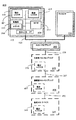
図1a、1b、2、3及び4は、本発明の様々な実施例を説明するためのシステム100、200、300及び400のブロック図を示す。プロセッサ130は、ホストバス120に接続される任意のプロセッサは表しているかもしれない。あるいは、プロセッサ130は、ホストバス120に接続される2つ以上のプロセッサを表しているかもしれない。
FIGS. 1 a, 1 b, 2, 3 and 4 show block diagrams of
システム100、200、300及び400は、例えば、ネットワークコントローラ、大容量記憶装置コントローラ、ディスプレイコントローラ、マルチメディアデバイス、通信デバイス、あるいはその他のデバイスとしてのホストバスデバイス110、210及び410を備える。ホストバスデバイス110、210及び410は、ホストバス120をモニタすることを可能にし、存在しない仮想PCIデバイス160を対象としたプロセッサ始動ホストバスサイクルをホストバスデバイス110が遮断できるよう、インタフェース112を介しホストバス120に接続されてもよい。
The
ホストバスデバイス110、210及び410は、ホストバスサイクルの追跡のためホストバス120に接続されたモニタ回路114を備えてもよい。モニタ回路114は、各ホストバスサイクルにおいて選択された情報を取得し、監視(snoop)あるいは遮断(intercept)される選択されたホストバスサイクルを特定する。リードサイクル(read cycle)は、データをホストバス120に転送するため選択されたホストバスデータ信号を駆動し、そして当該サイクルを終了させることにより遮断される。プロセッサ130により始動されたサイクルは、アクティブなプロセッサ130にホストバス120により利用されているプロトコルに従って、いつ当該サイクルを終了すべきかを通知することにより終了される。ライトサイクル(write cycle)は、ホストバス120のライトサイクルにおける選択されたホストバス120のデータ信号の値をラッチし、その後当該サイクルを終了させることにより遮断される。ホストバス120のサイクルは、選択されたホストバスサイクルの情報を読み出し、それを記憶装置115に保存することにより監視される。ここで、当該サイクルは典型的にはホストバス120に接続された他のデバイスにより終了させられる。
ホストバスデバイス110、210及び410は、記憶装置111のコンテンツがホストバス120を介しアクセス可能となるようホストバス120に接続される記憶装置111を備えてもよい。記憶装置111の様々な実施形態として、システム設定空間またはRAM(Random Access Memory)に備えられたレジスタ216、218及び417、あるいはシステムI/Oまたはメモリアドレス空間に備えられたレジスタやデータポートが含まれてもよい。
The
PCIプロトコルは、PCIデバイスが備えられる各PCIバスのある個数のアドレス可能なスロットを提供する。PCI−PCIブリッジは、2つのPCIバス間の転送パスを提供するPCIデバイスである。コンピュータプログラムは、典型的に、検出されたPCI−PCIブリッジの直後にある各PCIバスに一意的なバス番号を割り当てる。PCIバス番号とスロット番号の組み合わせは、設定空間を通じシステムにインストールされる任意のPCIデバイスの選択のため、コンピュータプログラムにより利用されるユニークな識別子を提供する。PCIアドレッシング及びルーティングプロトコルは、一般に、あるPCIデバイスがホスト−PCIブリッジと恐らく1つ以上のPCI−PCIブリッジを介し物理的にルーティングされ、ターゲットPCIデバイスが備えられるPCIバスにおけるサイクルを生成する物理階層バス構造を想定している。各PCIバスは、当該PCIバスとホストバスの間の物理的/仮想的データ転送パスにおける任意のPCIバスの後方にあると定義される。 The PCI protocol provides a certain number of addressable slots for each PCI bus with which a PCI device is provided. A PCI-PCI bridge is a PCI device that provides a transfer path between two PCI buses. The computer program typically assigns a unique bus number to each PCI bus that immediately follows a detected PCI-PCI bridge. The combination of PCI bus number and slot number provides a unique identifier used by the computer program for selection of any PCI device installed in the system through the configuration space. The PCI addressing and routing protocol is generally a physical hierarchy in which a PCI device is physically routed through a host-PCI bridge and possibly one or more PCI-PCI bridges to generate cycles on the PCI bus on which the target PCI device is equipped. A bus structure is assumed. Each PCI bus is defined to be behind any PCI bus in the physical / virtual data transfer path between the PCI bus and the host bus.
本明細書において、主(primary)PCIバス150は、バス番号が0で、ホスト−PCIブリッジの直後のバスであるかもしれない。しかし、PCIバス150はまた、仮想PCI装置150が後方に現れ、システムに複数の主PCIバスが存在するため、本発明による方法と適合したバス番号0の後方にある任意のPCIバスであってもよい。さらに、主PCIバス160は実際のPCIバスでもよいし、あるいは仮想的なものであってもよい。本明細書において、仮想的と論理的という2つの単語は、実際の物理的デバイスや構造を反映しない効果を有する1つ以上のプロセッサ130上で実行されるコンピュータプログラムの一面を指すものである。仮想PCIデバイス160は、論理的にはPCIバス151にあり、主PCIバス150を拡張したもの、あるいはそれの下位のものの1つ(すなわち、主PCIバス150の後方にあるバス)である。
In this specification, the
ホスト−PCIブリッジ140、240及び340は、選択されたホストバス120のサイクルの主PCIバス150及びそれの下位バス(subordinate bus)への解釈及びルーティングを容易にするかもしれない。ホスト−PCIブリッジ140、240及び340は、ホストバスインタフェース141、PCIバスインタフェース142、記憶装置145及び149、ホストバス120のサイクルを追跡する制御回路148を備え、各ホストバスサイクルに対し、当該ホストバスサイクルを実際の主PCIバス150にルーティングすべきかどうか判断するようにしてもよい。この判断のため、制御回路148は記憶装置145を参照し、主PCIバス150とその下位バスに割り当てられているアドレス空間を特定し、記憶装置149を参照し、仮想PCIデバイス160あるいは恐らく他の仮想デバイスに割り当てられているアドレス空間を特定する。記憶装置145と149は、バス番号、メモリアドレスレンジ、I/Oアドレスレンジあるいは他の同様の情報の形式で情報を保持している。記憶装置149における情報は、仮想PCIデバイス160(より複雑な設定では、仮想デバイスまたはバスのすべてあるいはその一部)に割り当てられているアドレスレンジを示すものであり、一般に、主PCIバス150及びそれの下位バスに割り当てられる記憶装置145におけるアドレス空間の一部であるかもしれない。仮想PCIデバイスを対象としたホストバスサイクルは、ホストバスデバイス110、210及び310による遮断が許されている。
Host-
ホストバス120がPentium3または4(登録商標)プロセッサを利用しているシステムでは、ホスト−PCIブリッジ140、240及び340は、すべてのホストバスサイクルに対し、ホストバスプロトコルに従いすべてのホストバスサイクルが完了したということを保証する応答装置であってもよく、ホストバスデバイス110は遮断を行う選択されたホストバスサイクルを要求してもよい。
In systems where the
仮想PCIデバイス160を対象とするホストバスサイクルの特定に必要な情報と、この情報の取得方法は、システムのバス構造に依存する。仮想PCIデバイス160の一意的なバスデバイス番号の組み合わせは、仮想PCIデバイス160が主PCIバス150上に論理的に設置されているシステム100のホストバスデバイス110とホスト−PCIブリッジの両方に、ハードウェア的に組み込まれるか、あるいはソフトウェア的に予めプログラムされる。
Information necessary for specifying a host bus cycle for the
システム100、200、300及び400が、複数のホストバスデバイス110、210及び410を備えること、あるいは各自がそこに統合された複数のホストバスデバイス110、210及び410を有する複数のプロセッサ130を備えることは、本発明による方法と適合している。本発明による方法は、各自が複数の仮想PCIデバイス160の1つと関連付けされる複数のホストバスデバイス110からなるシステム100に適用することができる。複数の仮想PCIデバイス160の1つを対象としたホストバス120のサイクルは、ホスト−PCIブリッジ140により主PCIバス150に転送されず、ホストバスデバイス110の1つが当該サイクルの遮断を許される。複数のホストバスデバイス110が、仮想PCIデバイスに割り当てられているシステムリソースを利用できるよう当該仮想PCIデバイス160に関連付けされる。その反対に、1つのホストバスデバイス110が複数の仮想PCIデバイス160に関連付けされてもよい。さらに、ホストバスデバイス110はPCIプロトコルに従い複数の昨日をサポートするよう構成されてもよい。複数のホストバスデバイス110が同一の仮想PCIデバイス160に対する遮断を行うことを防ぐための方策は、それに関連付けされた仮想PCIデバイス160を特定する一意的なバスデバイス番号の組み合わせにより、各ホストバスデバイス110をハードウェア的に組み込んだり、あるいはソフトウェア的に予めプログラムすることにより実行される。
The
図1aは、プロセッサ130とのホストバスインタフェースとは異なるインタフェース112を介しホストバスに接続されるホストバスデバイス110を示す。図1bは、プロセッサ130とホストバスデバイス110が、内部バス113及び共有ホストバスインタフェース112を介しホストバス120に接続されている本発明による方法と適合した他の構成を示す。図1bのシステムは、ホストバスデバイス110とプロセッサ130を1つの回路パッケージに統合することにより構成されうる。
FIG. 1 a shows a
図2は、図1に示されたシステム100の教示に従う本発明の一実施例を説明するシステム200を示す。システム200は、設定空間を介しアクセス可能な256の8ビット設定レジスタ268を有する、1つ以上のプロセッサ130において実行されるコンピュータプログラムの関し利用される仮想PCIデバイス160を備える。必要かつ関連性のある設定レジスタ268のみが実現される。PCIプロトコルによると、ユーザによる操作を必要とせず、システムマップ構成における仮想PCIデバイスを含む、コンピュータプログラムは仮想PCIデバイス160の検出、仮想デバイス160のシステムリソース要件を判断するためのベンダーとデバイスタイプの特定、完全なデバイス再配置の提供、バインディングの中断、インストール、設定及び起動を含む1つ以上の機能を達成するため、仮想設定レジスタ268へのアクセスを開始してもよい。
FIG. 2 shows a
ホストバスデバイス210は、本実施例において、PCIに準拠する設定レジスタ218からなるホストバス記憶装置111を備えてもよい。必要かつ関連性のあるレジスタ218のみが実現される。モニタ回路114は、ホストバスサイクルを追跡し、ホストバスデバイス設定レジスタ218にアクセスするため遮断及びリダイレクトを行う仮想設定レジスタ268を対象とするホストバスサイクルを特定する。この結果、プロセッサ130上で実行されるコンピュータプログラムは、仮想PCIデバイス160の設定レジスタ268を対象とするホストバスサイクルを始動させることにより、ホストバスデバイス設定レジスタ218にアクセスすることができる。このように、ホストバスデバイス210は、一般に利用可能なシステムリソースにPCIデバイスを割り当てる初期化及び設定処理に入る。
In this embodiment, the
設定サイクルは、PCIプロトコルにより与えられた2つのマッピング機構の1つを通じ、システム200において生成される。第1の機構は、典型的には、ホスト−PCIブリッジ240に含まれる設定アドレスレジスタ243と設定データレジスタ244のためにプロセッサI/Oスペースの2つの固定された場所が予約されるインデックス方式である。設定アドレスレジスタ243は、設定空間をイネーブルあるいはディスイネーブルにし、以降の設定サイクルが対象とするバス番号、デバイス番号、機能番号及びレジスタ番号を指定することにより、PCIデバイスと設定レジスタを特定するコンピュータプログラムにより書き込まれる。設定データレジスタ244を対象とした以降のDWORDリード・ライトホストバスサイクルは、典型的には、ホスト−PCIブリッジ240により、PCIに準拠した設定サイクルに変換およびルーティングされる。しかしながら、仮想PCIデバイス160の設置レジスタ268を対象としたホストバスサイクルは、PCIプロトコルにより予期されるように、ホスト−PCIブリッジ240によりルーティングされるよりも、ホストバスデバイス210により遮断される。
The setup cycle is generated in the
第1機構をサポートするシステム200は、監視により取得された選択情報を保持する記憶装置115に含まれるミラーレジスタ216を備えてもよい。設定アドレスレジスタ243を対象としたホストバス120のライトサイクルは、ホストバスデバイス210により監視されてもよいし、監視されたサイクルで転送されるデータは設定アドレスレジスタ243のコンテンツを反映するミラーレジスタ216に格納されてもよい。モニタ回路114は、仮想設定レジスタ268にアクセスする設定データレジスタ244を対象とした以降のDWORDホストバス120のサイクルを特定するため、ミラーレジスタ216を参照してもよい。これらの特定されたサイクルは、ホストバスデバイス210により遮断され、ホストバスデバイス210の対応する設定レジスタ218にアクセスするためリダイレクトされる。
The
また、システム200は、第2の機構をサポートするものであってもよい。この第2の機構では、典型的には、ホスト−PCIブリッジ240に配置される設定空間イネーブルレジスタ(図示せず)と転送レジスタ(図示せず)が、プロセッサI/Oアドレス空間における固定された場所にマップされる設定空間の4kバイトを指定するコンピュータプログラムにより書き込みされる。第2機構をサポートするよう設計されたシステム200は、設定空間イネーブルレジスタ(図示せず)と転送レジスタ(図示せず)を対象とした検索されたホストバスライトサイクルを格納するミラーレジスタ216を備えてもよい。仮想デバイスの設定レジスタ268を対象としたホストバスサイクルを特定するため、ミラーレジスタ216がモニタ回路114により参照されてもよい。特定されたサイクルは、ホストバスデバイス210により遮断され、ホストバスデバイス210の対応する設定レジスタ218にアクセスするようリダイレクトされる。
Further, the
PCIプロトコルに従って、設定レジスタは、割り込み、プロセッサメモリアドレス空間、プロセッサI/Oアドレス空間、及びROM(Read Only Memory)に予約されたプロセッサメモリアドレス空間のレンジであるROMアドレス空間を含むシステムリソースの割当を実行するコンピュータプログラムにより利用されてもよい。コンピュータプログラムは、仮想PCIデバイス160のシステム要件を判断し、選択された設定レジスタ268への書き込みにより仮想PCIデバイス160にリソースを割り当てるため、存在しない仮想設定レジスタ268へのアクセスを開始してもよい。コンピュータプログラムはまた、致命的なエラーを処理すると共に、内蔵されている自己診断テスト(BIST)の実行及びその状態の取得を行う仮想デバイスの設定レジスタ268にアクセスするようにしてもよい。
In accordance with the PCI protocol, the configuration register allocates system resources including an interrupt, a processor memory address space, a processor I / O address space, and a ROM address space that is a range of processor memory address space reserved in ROM (Read Only Memory). It may be used by a computer program that executes The computer program may determine the system requirements of the
選択的には、ホストバスデバイス設定レジスタ218は、例えば、仮想PCIデバイス260に割り当てられるメモリ空間またはI/O空間の1つ以上のレンジである特定のシステムリソースのリクエストを示すよう実現されてもよい。内部記憶装置111の一部は、コンピュータプログラムにより、ホストバス120を介したアクセスのため当該アドレス空間にマップされてもよい。コンピュータプログラムによるアドレス空間の仮想PCIデバイス160への割当後、この選択的実施例において、モニタ回路114は、ホストバスサイクルが仮想PCIデバイス160に割り当てられるメモリあるいはI/O空間を対象としているかどうか特定するため、適当な設定レジスタ218を参照するようにしてもよい。これら特定されたサイクルは、ホストバスデバイス210により遮断され、ホストバス記憶装置111にアクセスするようリダイレクトされてもよい。
Optionally, the host bus
ホストバスデバイス210とホスト−PCIブリッジ240は、仮想PCIデバイス160のバス番号とデバイス番号を把握するようにしてもよい。このような情報は、ハードウェア的に組み込まれてもよいし、ソフトウェア的に予めプログラムされてもよいし、あるいはシステムの初期化においてプログラムにより提供されるようにしてもよく、仮想PCIデバイス160の設定空間を対象としたホストバスサイクルの特定に利用される。ホスト−PCIブリッジ240は、仮想PCIデバイス160に割り当てられたアドレス空間を指定する仮想設定レジスタ268を対象とする選択されたホストナスライトサイクルを監視することにより、仮想PCIデバイス160に割り当てられたアドレス空間を把握ようにしてもよい。
The
図3は、システム100及び200の教示に従う本発明の一実施例を説明するシステム300を示す。システム300は、設定空間にアクセスする第1機構を実現したものである。システム300は、プロセッサ130上で実行されるコンピュータプログラムに対し、主PCIバス150上の配置として、そして主仮想PCIバス357へのブリッジとして利用される主仮想PCI−PCI(P−P)ブリッジ370から構成されてもよい。仮想PCIデバイス360は、プロセッサ130上で実行されるコンピュータプログラムに対して、主仮想バス357上の配置として利用されてもよい。
FIG. 3 shows a
本実施例において、ホストバスデバイス210とホスト−PCIブリッジ340は共に、主仮想PCI−PCIブリッジ370配置されているバス番号とデバイス番号を把握し、ホストバスデバイス210は仮想PCIデバイス360のデバイス番号を把握している。この情報は、初期化プログラムにより与えられてもよいし、ハードウェア的に組み込まれても、ソフトウェア的に予めプログラムされていてもよい。
In this embodiment, both the
ホスト−PCIブリッジ340は、本実施例において、例えば、プラグ・アンド・プレイ(登録商標)リソース割当プログラムのような、主PCIバス150にアドレス空間を割り当てるため、コンピュータプログラムにより書き込まれる、仮想デバイス160に割り当てられるすべてのアドレス空間を網羅する記憶装置149を備えてもよい。記憶装置149に格納される情報は、主PCIバス357の後方にある仮想バス(図示せず)のバス番号を含むものであってもよい。通常、バス番号は、主PCIバス357やその下位バスに割り当てられる設定空間を決定するのに十分な情報である。選択的に、記憶装置149には、主PCIバス357と下位バスに割り当てられるメモリ空間またはI/O空間が含まれてもよい。本実施例では、プラグ・アンド・プレイ(登録商標)プロトコルに従って、主PCIバス357に割り当てられたアドレス空間は、典型的には、選択的な下位バス(図示せず)と仮想PCIデバイス160に割り当てられたアドレス空間を網羅し、これにより、仮想PCIバス357と選択的な下位仮想バスを対象としたホストバスサイクルの特定のため、ホスト−PCIブリッジ340による容易かつ効率的復号化が可能となる。
In this embodiment, the host-
ホスト−PCIブリッジ340は、主仮想PCI−PCIブリッジ370の仮想設定レジスタ378を対象としたホストバスサイクルの特定、及びこれら特定されたサイクルのホスト−PCIブリッジ設定レジスタ347へのルーティングを実行するため、制御回路148により参照されるブリッジ設定レジスタ347を備えてもよい。本実施例において、制御回路148は、ホストバスサイクルを主PCIバス150にルーティングすべきか判断するため、ブリッジ設定レジスタ347及び記憶装置145と149を参照するようにしてもよい。
The host-
ホストバスデバイス210は、主仮想PCI−PCIブリッジ370の設定レジスタ378を対象としたホストバスサイクルを生成し、コンピュータプログラムにより主仮想PCIバス357に割り当てられたバス番号を取得し、この情報を監視により取得される選択された情報を保持する記憶装置115に格納するようにしてもよい。1つのホストバスデバイス210のみを有するシステムは、デバイス番号を仮想PCIデバイス160に任意に割り当ててもよい。複数のホストバスデバイス210を有するシステムは、ハードウェア的に組み込まれててもよいし、ソフトウェア的に予めプログラムされてもよいし、初期化プログラムにより格納されてもよい一意的なデバイス番号(すなわち、スロット番号)を各ホストバスデバイス210に与えるなど、各ホストバスデバイス210を相異なる仮想PCIデバイス360に関連付けるための機構を要するかもしれない。
The
図4は、図3に示されるシステム300の教示に従う本発明の一実施例を説明するためのシステム400を示す。ホストバスデバイス410は、ホストバスデバイス210と310に対し与えられた説明に従うものであってもよい。システム400は、設定空間にアクセスする第1機構を実現するものである。システム400はさらに、副(secondary)仮想PCIバス451に直接接する副仮想PCI−PCIブリッジ490を備える。副仮想PCI−PCIブリッジ490は、プロセッサ130上で実行されるコンピュータプログラムの観点から、主仮想PCIバス上の配置に利用され、仮想PCIデバイス160は副仮想PCIバス451に論理的に配置されてもよい。
FIG. 4 shows a
副仮想バス451は、主仮想PCIバス357に従属し、本実施例では、副仮想バス451と仮想PCIデバイス160に割り当てられるアドレス空間は、主仮想PCIバス357に割り当てられるアドレス空間内にある。ホスト−PCIブリッジ340は、主PCIバス150とその下位バスを対象とするホストバスサイクルの特定及びルーティングのため記憶装置145を参照し、主仮想バス357とその下位バスを対象とするホストバスサイクルの特定のため記憶装置149を参照する。主仮想バス357とその下位バスを対象とするホストバスサイクルは、主PCIバス450に転送されず、ホストバスデバイス410による遮断が許可される。ホスト−PCIブリッジ340は、ホストバスプロトコルに従い、遮断したホストバス430のサイクルを完了(すなわち終了)させることができる。
The secondary
ホストバスデバイス410は、ホストバスに接続され、プロセッサ130にアクセス可能な記憶装置111を備えてもよい。記憶装置111は、仮想PCIデバイス160の設定レジスタ268を対象とするホストナスサイクルによりアクセスされるデバイス設置レジスタ218を備えてもよい。さらに、記憶装置111は、仮想副PCI−PCIブリッジ490の仮想設定レジスタ497を対象としたホストバスサイクルによりアクセスされるブリッジ設定レジスタ417を備えてもよい。
The
本実施例では、システム300と同様に、ホストバスデバイス410とホスト−PCIブリッジ340は、主仮想PCI−PCIブリッジ370が配置されるバス番号とデバイス番号を把握している。この情報は、初期化プログラムにより提供されてもよいし、ハードウェア的に組み込まれていてもよいし、ソフトウェア的に予めプログラムされていてもよい。さらに、本実施例において、ホストバスデバイス410は、主仮想PCI−PCIブリッジ370の設定レジスタ378を対象としたホストバスサイクルを監視することによって、主仮想PCIバス357とその下位バスに割り当てられたバス番号を取得してもよい。単一のホストバスデバイス410からなるシステム400では、副仮想PCI−PCIブリッジ490のデバイス番号は任意に割り当てることができる。
In this embodiment, as in the
複数のホストナスデバイス410からなるシステムでは、例えば、関連付けされた副仮想PCI−PCIブリッジ490の一意的なデバイス番号を各ホストバスデバイス410に割り当てるような、各ホストバスデバイスを相異なる副仮想PCI−PCIブリッジ490に関連付けるための機構が必要となり、この割り当ては、ハードウェア的に組み込まれてもよいし、ソフトウェア的に予めプログラムされてもよいし、あるいは初期化プログラムにより実行されてもよい。各ホストバスデバイス410は、コンピュータプログラムによる書き込み後、関連付けされている副仮想PCI−PCIブリッジの直後の副仮想バス451に割り当てられているバス番号を決定するため、その内部設定レジスタ417を参照し、各仮想PCIデバイス460にデバイス番号を任意に割り当てる。この情報は、システム100に関して説明された方法と同様にして、仮想PCIデバイス160を対象としたホストバスサイクルの特定のため、モニタ回路114により参照されてもよい。各ホストバスデバイス410は、各々がそれに関連付けされた副仮想PCIバス451に論理的に配置される相異なる仮想デバイス160と関連付けされている複数の物理的なデバイスを備えてもよい。プラグ・アンド・プレイ(登録商標)プログラムは、典型的には、各副仮想PCI−PCIブリッジ490の後方に配置されたすべての仮想デバイス160に割り当てられるリソースを分類し、その結果、遮断されるサイクルの特定のため各ホストバスデバイス410によるホストバスサイクルの復号化が容易になる。例えば、単一のメモリアドレスレンジが、各デバイスに割り当てられた複数のレンジを網羅する副仮想PCI−PCIブリッジ490に割り当てられてもよい。
In a system composed of a plurality of
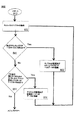
図5は、システム100、200、300及び400により利用され、モニタ回路114により実行される本発明による方法500を説明するフロー図を示す。スタートステップ510は、記憶装置とレジスタにデフォルト値を設定するホストバスのリセットである。各ホストバスサイクルに対し、以下の各ステップが実行される。獲得ステップ520は、ホストバスサイクルを待機し、カレントホストバスサイクルの対象を示す選択されたホストバスアドレスと制御信号の受信及びラッチングに関する処理である。次の評価ステップ540は、獲得した各サイクルを評価し、遮断ステップ550に進むか、監視ステップ560に進むか判断する。監視ステップ560は、選択されたホストバスデータ信号の受信及び格納に関する処理である。評価ステップ550は、獲得した各サイクルを評価し、カレントサイクルに対し処理を行わず、ステップ520に進み、次のホストバスサイクルを獲得するか、あるいはサイクルの遮断ステップ580に進み、ホストバス記憶装置111内の適当な場所にアクセス(すなわち、読み出し、または書き込み)するため、カレントホストナスサイクルをルーティングさせるかどうか判断する。ステップ540と550はパラレルに実行されてもよいし、何れか一方が先行して実行されてもよい。
FIG. 5 shows a flow diagram illustrating the
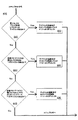
図6a及び図6bは、図4に示されたシステム400のモニタ回路114により実行される方法600を説明するフロー図を示す。スタートステップ610及び獲得ステップ620は、それぞれステップ510と520に関する説明と同様である。評価ステップ540及び監視ステップ560は、ステップ641、642、662及び664によりなされる。同様に、評価ステップ550及び遮断ステップ580は、ステップ643、644、645、682、684及び686によりなされる。評価ステップ641〜645はホストバスサイクルのアドレス段階において実質的にパラレルに実行され、監視ステップ662と664、あるいは遮断ステップ682、684と686が実行される場合、当該監視あるいは遮断ステップはホストバスサイクルのデータ段階において実行される。監視されたサイクルは、ホストバスデバイス410以外のデバイスにより完了させられ(例えば、終了させられ)、遮断されたサイクルはホストバスデバイス410により完了させられる。
6a and 6b show a flow diagram illustrating a
評価ステップ641では、獲得されたカレントホストバスサイクルが設定アドレスレジスタ243を対象としているか評価される。肯定的に評価されると、ステップ662に進み、獲得されたカレントサイクルにより転送されるデータが監視され、このデータの一部あるいは前部がミラーレジスタ216に格納される。否定的に評価されると、ステップ642に進む。
In an
評価ステップ642では、獲得されたホストバスサイクルが、主仮想PCI−PCIブリッジ370にバス番号を割り当てるため、特定の仮想設定レジスタ378を対象としているかどうか評価される。この評価が肯定されるには、(ミラーレジスタ216のコンテンツにより反映されるような)設定アドレスレジスタ243が、設定空間がイネーブルであることを示す値と、主仮想バス357に割り当てられるバス番号を指定する主仮想PCI−PCIブリッジ370の設定レジスタ378を現在指定している値を有することが要求される。また、肯定的な評価には、獲得されたサイクルが設定データレジスタ244を対象にしたリード/ライトホストバスサイクルであることが要求される。ステップ642において肯定的な評価がなされると、監視ステップ664に進み、カレントサイクルで転送される一部あるいはすべてのホストバス120のデータが記憶装置115にラッチ及び格納される。
In an
評価ステップ643では、カレントサイクルが副PCI−PCIブリッジ490の設定空間を対象としているかどうか評価される。この評価が肯定されるには、(ミラーレジスタ216のコンテンツにより反映されるような)設定アドレスレジスタ243が、設定空間がイネーブルであることを示す値と、副PCI−PCIブリッジ490の設定レジスタ497を現在指定している値を有することが要求される。また、肯定的な評価には、獲得されたサイクルが設定データレジスタ244を対象としたリード/ライトホストバスサイクルであることが要求される。ステップ643において肯定的な評価がなされると、遮断ステップ682に進み、カレントホストバスサイクルが副仮想PCI−PCIブリッジ490の設定レジスタ417にルーティングされる。ここで、評価される設定レジスタ417は、ミラーレジスタ216の現在のコンテンツにより決定される。
In an
評価ステップ644では、獲得したホストバスサイクルが仮想PCIデバイス160の設定空間を対象としているかどうか評価される。この評価が肯定されるには、(ミラーレジスタ216のコンテンツにより反映されるような)設定アドレスレジスタ243が、設定空間がイネーブルであることを示す値と、仮想PCIデバイス160の設定レジスタ268を現在指定している値を有することが要求される。また、獲得されたサイクルが設定データレジスタ244を対象にしたリード/ライトホストバスサイクルであることが要求される。ステップ644において肯定的な評価がなされると、遮断ステップ684に進み、ミラーレジスタ216のコンテンツにより示されるように、ホストバス設定レジスタ218にアクセスするようカレントホストバスサイクルはルーティングされる。
In an
評価ステップ645では、獲得されたホストバスサイクルが、コンピュータプログラムにより仮想PCIデバイス160に割り当てられたメモリまたはI/Oアドレス空間を対象としているどうかが評価される。仮想PCIデバイス460に割り当てられたメモリあるいはI/O空間を特定する設定レジスタ218が以前に設定されていない場合、評価結果は常に否定的なものとなる。PCI設定レジスタ218の現在のコンテンツにより決定されるように、仮想PCIデバイス160に割り当てられたアドレス空間が、獲得されたホストバスサイクル情報と比較される。カレントホストバスサイクルの対象が仮想PCIデバイス160に割り当てられたアドレス空間内のものである場合、ステップ686に進み、獲得されたホストバスサイクルのアドレス及び制御信号により示されるように、カレントホストバス420のサイクルが適当な内部記憶装置111にルーティングされる。
In an
ここで説明された機能が、本発明の意図を留める限り、説明された以外の物理的デバイスにおいて実現されうるということは当業者には理解されるであろう。 Those skilled in the art will appreciate that the functions described herein may be implemented in physical devices other than those described, so long as the intent of the present invention remains.
本発明はPCIシステムに適用したものとして説明されてきたが、ここで教示された方法は、ホストバス及び(PCIに準拠したバスに類似の)周辺バスを有する任意のシステムにより利用可能であり、システムのプロセッサ上で実行されるコンピュータプログラムに対し、周辺バスにおける配置として利用されるホストバスに接続されたデバイスを備えることにより効果が得られるということは当業者には理解されるであろう。 Although the present invention has been described as applied to a PCI system, the method taught herein can be used by any system having a host bus and a peripheral bus (similar to a PCI-compliant bus); Those skilled in the art will appreciate that for a computer program running on the processor of the system, it would be advantageous to have a device connected to a host bus that is utilized as an arrangement in the peripheral bus.
Claims (30)
1以上の機能を実行するよう前記インタフェースと接続され、仮想PCIデバイスとして出現し、前記host−to−PCIブリッジを介し前記ホストバスに接続されるPCIバス上に論理的に設けられるデバイスと、
前記ホストバスに接続される前記プロセッサの少なくとも1つにより開始されるホストバスサイクルを追跡するよう前記デバイスと前記インタフェースに接続され、前記仮想PCIデバイスを対象とするプロセッサにより開始されたホストバスサイクルを特定し、前記仮想PCIデバイスとして前記デバイスが前記host−to−PCIブリッジにアクセスする必要なく、前記仮想PCIデバイスを対象とする特定されたホストバスサイクルの1以上に応答することを可能にするよう1以上の制御信号を生成するモニタ回路と、
から構成される装置であって、
前記デバイスによる前記host−to−PCIブリッジへのアクセスは、前記ホストバスを介してのみ行われることを特徴とする装置。an interface for connecting directly to a host bus having one or more processors without being shared with host-to-PCI bridge,
A device logically provided on a PCI bus connected to the interface to perform one or more functions, appearing as a virtual PCI device, and connected to the host bus via the host-to-PCI bridge;
Host bus cycles initiated by a processor connected to the device and the interface and directed to the virtual PCI device to track host bus cycles initiated by at least one of the processors connected to the host bus. Identify and allow the device as the virtual PCI device to respond to one or more of the identified host bus cycles intended for the virtual PCI device without having to access the host-to-PCI bridge A monitor circuit for generating one or more control signals;
A device comprising:
The device is characterized in that access to the host-to-PCI bridge by the device is performed only via the host bus.
前記インタフェースと前記モニタ回路に接続され、前記仮想PCIデバイスにアドレス指定されたホストバスリードサイクルに係るデータを格納する第1ストレージを有し、
前記データは、前記host−to−PCIブリッジのホストインタフェースにアクセスすることなく、前記ホストバスリードサイクル中に前記第1ストレージから前記ホストバスに転送されることを特徴とする装置。The apparatus of claim 1, further comprising:
A first storage connected to the interface and the monitor circuit for storing data relating to a host bus read cycle addressed to the virtual PCI device;
The apparatus is characterized in that the data is transferred from the first storage to the host bus during the host bus read cycle without accessing the host interface of the host-to-PCI bridge.
前記インタフェースと前記モニタ回路に接続され、前記仮想PCIデバイスにアドレス指定されたホストバスライトサイクルに係るデータを格納する第2ストレージを有し、
前記データは、前記host−to−PCIブリッジのホストインタフェースにアクセスすることなく、前記ホストバスライトサイクル中に前記ホストバスから前記第2ストレージに転送されることを特徴とする装置。The apparatus of claim 2, further comprising:
A second storage connected to the interface and the monitor circuit for storing data relating to a host bus write cycle addressed to the virtual PCI device;
The apparatus is characterized in that the data is transferred from the host bus to the second storage during the host bus write cycle without accessing the host interface of the host-to-PCI bridge.
前記インタフェースに接続され、該インタフェースを介し前記ホストバス上で1以上のホストバスサイクルを開始可能なプロセッサを有することを特徴とする装置。The apparatus of claim 1, further comprising:
An apparatus comprising: a processor connected to the interface and capable of initiating one or more host bus cycles on the host bus via the interface.
前記デバイス、前記モニタ回路、前記第1ストレージ及び前記第2ストレージを前記インタフェースに接続する内部バスを有することを特徴とする装置。The apparatus of claim 3, further comprising:
An apparatus comprising: an internal bus connecting the device, the monitor circuit, the first storage, and the second storage to the interface.
前記デバイスは、1以上の他のデバイスに接続されるブリッジデバイスであり、前記host−to−PCIブリッジに接続されるPCIバスに論理的に設けられる仮想PCI−PCIブリッジとして出現することを特徴とする装置。The apparatus of claim 1, comprising:
The device is a bridge device connected to one or more other devices, and appears as a virtual PCI-PCI bridge logically provided on a PCI bus connected to the host-to-PCI bridge. Device to do.
前記仮想PCIデバイスを対象とする前記特定されたホストバスサイクルは、前記仮想PCIデバイスに割当てられたメモリアドレス空間を対象とするホストバスサイクルを有することを特徴とする装置。The apparatus of claim 1, comprising:
The apparatus characterized in that the identified host bus cycle targeted for the virtual PCI device comprises a host bus cycle targeted for a memory address space allocated to the virtual PCI device.
前記ホストバスに接続され、前記ホストバスからデータを受信するための前記制御信号の1以上に応答するミラーレジスタを有し、
前記モニタ回路は、設定アドレスレジスタを対象とするホストバスライトサイクルをさらに特定し、前記設定アドレスレジスタを対象とするものとして特定された前記ホストバスサイクルの期間中に前記ミラーレジスタに格納するため、前記ホストバスからデータを受信するための前記制御信号を生成する、
ことを特徴とする装置。The apparatus of claim 1, further comprising:
A mirror register connected to the host bus and responsive to one or more of the control signals for receiving data from the host bus;
The monitor circuit further identifies a host bus write cycle targeted at a set address register and stores it in the mirror register during the host bus cycle identified as targeted for the set address register, Generating the control signal for receiving data from the host bus;
A device characterized by that.
前記仮想PCIデバイスを対象とする前記特定されたホストバスサイクルは、前記仮想PCIデバイスに割当てられたI/Oアドレス空間に対するホストバスサイクルを有することを特徴とする装置。The apparatus of claim 1, comprising:
The apparatus characterized in that the identified host bus cycle intended for the virtual PCI device comprises a host bus cycle for an I / O address space allocated to the virtual PCI device.
前記第1ストレージは、複数の第1設定レジスタを有し、
前記特定されたホストバスサイクルは、前記仮想PCIデバイスに対し確保されている設定空間を対象とするホストバスサイクルを有することを特徴とする装置。The apparatus of claim 2, comprising:
The first storage has a plurality of first setting registers,
The specified host bus cycle includes a host bus cycle for a setting space reserved for the virtual PCI device.
前記仮想PCIデバイスは、仮想PCI−to−PCIブリッジの後方に配置され、
前記第1ストレージは、複数の第2設定レジスタを有し、
前記モニタ回路は、前記仮想PCI−to−PCIブリッジに割当てられた設定空間を対象とするホストバスサイクルをさらに特定し、
前記モニタ回路は、前記仮想PCI−to−PCIブリッジに割当てられた設定空間を対象とする前記特定されたホストバスリードサイクルの1以上において、1以上の前記データを前記ホストバスに伝送する複数の制御信号を生成する、
ことを特徴とする装置。The apparatus of claim 10, comprising:
The virtual PCI device is disposed behind a virtual PCI-to-PCI bridge,
The first storage has a plurality of second setting registers,
The monitor circuit further identifies a host bus cycle that targets a setting space allocated to the virtual PCI-to-PCI bridge;
The monitor circuit transmits a plurality of the data to the host bus in one or more of the specified host bus read cycles for the specified space assigned to the virtual PCI-to-PCI bridge. Generate control signals,
A device characterized by that.
プライマリPCIバスに割当てられた第1アドレス空間を指定するコンテンツを有する第1ストレージと、
1以上の機能を実行するよう前記インタフェースに接続され、仮想PCIデバイスとし出現し、前記プライマリPCIバスに接続されるPCIバス上に論理的に配置され、前記host−to−PCIブリッジへのアクセスが前記ホストバスを介してのみなされるデバイスと、
前記仮想PCIデバイスに割当てられる第2アドレス空間を指定するコンテンツを有する第2ストレージと、
前記第1ストレージと前記第2ストレージに接続され、プロセッサにより開始されたホストバスサイクルを追跡し、前記プライマリPCIバスにルーティングするホストバスサイクルを選択するようホストバスに接続する制御回路と、
から構成される装置であって、
前記ルーティングされたサイクルは、前記第2アドレス空間を対象とするホストバスサイクルを排除するため、前記第1ストレージと前記第2ストレージのコンテンツに基づき選択されることを特徴とする装置。an interface for connecting directly to a host bus without being shared with a host-to-PCI bridge;
A first storage having content specifying a first address space assigned to the primary PCI bus;
Connected to the interface to perform one or more functions, appearing as a virtual PCI device, logically located on a PCI bus connected to the primary PCI bus, and accessing the host-to-PCI bridge Devices made only via the host bus;
A second storage having content specifying a second address space allocated to the virtual PCI device;
A control circuit connected to the first bus and the second storage, connected to the host bus to track a host bus cycle initiated by a processor and to select a host bus cycle to route to the primary PCI bus;
A device comprising:
The apparatus is characterized in that the routed cycle is selected based on the contents of the first storage and the second storage to eliminate host bus cycles directed to the second address space.
前記第1及び第2アドレス空間は、メモリホストバスアドレス空間を含むことを特徴とする装置。The apparatus of claim 12, wherein
The apparatus of claim 1, wherein the first and second address spaces include a memory host bus address space.
前記第1及び第2アドレス空間は、ホストバスI/O空間を含むことを特徴とする装置。The apparatus of claim 12, wherein
The apparatus wherein the first and second address spaces include a host bus I / O space.
前記第1及び第2アドレス空間は、PCIに準拠した設定アドレス空間を含むことを特徴とする装置。The apparatus of claim 12, wherein
The apparatus according to claim 1, wherein the first and second address spaces include a set address space compliant with PCI.
前記仮想PCIデバイスは、仮想PCI−to−PCIブリッジであることを特徴とする装置。The apparatus of claim 12, wherein
The virtual PCI device is a virtual PCI-to-PCI bridge.
複数の設定レジスタと、
前記制御回路に接続され、前記仮想PCI−to−PCIブリッジが論理的に配備されるデバイス番号とバスを示すコンテンツを有する第3ストレージと、
を有し、
前記制御回路はさらに、前記バス及びデバイス番号に基づき、前記host−to−PCIブリッジのホストインタフェースにアクセスする必要なく前記複数の設定レジスタにルーティングするよう前記仮想PCI−to−PCIブリッジの設定アドレス空間を対象とするホストバスサイクルを選択することを特徴とする装置。The apparatus of claim 16, further comprising:
Multiple configuration registers,
A third storage connected to the control circuit and having a content indicating a device number and a bus on which the virtual PCI-to-PCI bridge is logically arranged;
Have
The control circuit further includes a setting address space of the virtual PCI-to-PCI bridge based on the bus and device number so as to route to the plurality of setting registers without having to access a host interface of the host-to-PCI bridge. Selecting a host bus cycle intended for
前記ホストバスにプライマリPCIバスを接続するhost−to−PCIブリッジと、
前記ホストバスに接続され、前記プライマリPCIバスに接続されたPCIバス上に論理的に配備される第1仮想PCIデバイスとして出現し、前記ホストバスをモニタし、前記第1仮想PCIデバイスを対象とするプロセッサにより開始されたホストバスサイクルを特定し、前記host−to−PCIブリッジにアクセスすることなく前記第1仮想PCIデバイスを対象とする特定されたサイクルを傍受し、前記host−to−PCIブリッジへの前記デバイスによるアクセスが前記ホストバスのみを介する第1ホストバスデバイスと、
から構成されるシステムであって、
前記host−to−PCIブリッジは、前記第1仮想PCIデバイスを対象とする前記host−to−PCIブリッジを介し接続される前記PCIバスに前記特定されたサイクルを転送しないことを特徴とするシステム。One or more processors connected to the host bus;
A host-to-PCI bridge connecting a primary PCI bus to the host bus;
Appears as a first virtual PCI device connected to the host bus and logically deployed on the PCI bus connected to the primary PCI bus, monitors the host bus, and targets the first virtual PCI device Identifying a host bus cycle initiated by a processor that intercepts the identified cycle intended for the first virtual PCI device without accessing the host-to-PCI bridge, and the host-to-PCI bridge A first host bus device through which the device accesses only via the host bus;
A system comprising:
The system, wherein the host-to-PCI bridge does not transfer the specified cycle to the PCI bus connected via the host-to-PCI bridge intended for the first virtual PCI device.
前記第1ホストバスデバイスは、複数の設定レジスタを有し、
前記傍受されたサイクルは、前記第1仮想PCIデバイスのため確保された設定空間を対象とするホストバスサイクルを有し、前記複数の設定レジスタにアクセスするようルーティングされる、
ことを特徴とするシステム。The system of claim 18, comprising:
The first host bus device has a plurality of setting registers,
The intercepted cycle has a host bus cycle directed to a configuration space reserved for the first virtual PCI device and is routed to access the plurality of configuration registers;
A system characterized by that.
前記第1ホストバスデバイスは、メモリ装置アレイを有し、
前記傍受されたサイクルは、前記第1仮想PCIデバイスに割当てられたメモリ空間を対象とするホストバスサイクルを有し、前記メモリ装置アレイにアクセスするようルーティングされる、
ことを特徴とするシステム。The system of claim 18, comprising:
The first host bus device has a memory device array;
The intercepted cycle has a host bus cycle directed to the memory space allocated to the first virtual PCI device and is routed to access the memory device array;
A system characterized by that.
前記ホストバスに接続され、前記プライマリPCIバスに接続されるPCIバス上に論理的に配備される第2仮想PCIデバイスとして出現する第2ホストバスデバイスを有し、
前記第1及び第2仮想PCIデバイスは、PCIバス番号とデバイス番号の一意的な組み合わせを有することを特徴とするシステム。The system of claim 18, further comprising:
A second host bus device that appears as a second virtual PCI device connected to the host bus and logically deployed on a PCI bus connected to the primary PCI bus;
The first and second virtual PCI devices have a unique combination of a PCI bus number and a device number.
前記第1仮想PCIデバイスは、プライマリ仮想PCI−to−PCIブリッジの後方に論理的に配置され、
前記プライマリ仮想PCI−to−PCIブリッジは、前記プライマリPCIバスの後方に論理的に配置され、
前記第1ホストバスデバイスは、前記プライマリ仮想PCI−to−PCIバスに割当てられたバス番号を決定するため、前記ホストバスを検索する、
ことを特徴とするシステム。The system of claim 18, comprising:
The first virtual PCI device is logically arranged behind a primary virtual PCI-to-PCI bridge,
The primary virtual PCI-to-PCI bridge is logically arranged behind the primary PCI bus,
The first host bus device searches the host bus to determine a bus number assigned to the primary virtual PCI-to-PCI bus;
A system characterized by that.
前記第1仮想PCIデバイスは、プライマリ仮想PCI−to−PCIブリッジの後方に論理的に配置される補助仮想PCI−to−PCIブリッジの後方に論理的に配置され、
前記第1ホストバスデバイスは、複数のブリッジ設定レジスタを有し、
前記傍受されたサイクルは、前記補助仮想PCI−to−PCIブリッジのために確保された設定空間を対象とするホストバスサイクルを有し、前記複数のブリッジ設定レジスタにアクセスするようルーティングされる、
ことを特徴とするシステム。The system of claim 22, wherein
The first virtual PCI device is logically disposed behind an auxiliary virtual PCI-to-PCI bridge that is logically disposed behind a primary virtual PCI-to-PCI bridge;
The first host bus device has a plurality of bridge setting registers,
The intercepted cycle has a host bus cycle directed to a configuration space reserved for the auxiliary virtual PCI-to-PCI bridge and is routed to access the plurality of bridge configuration registers;
A system characterized by that.
前記キャプチャされたサイクルが、プライマリPCIバスの後方のPCIバスに論理的に配置され、前記ホストバスにアクセスするため、host−to−PCIブリッジとインタフェースを共有し、前記host−to−PCIブリッジのホストインタフェースにアクセスする必要なく、前記ホストバスに直接接続されたホストバスデバイスを表す仮想PCIデバイスを対象としているか判断するステップと、
前記現在のサイクルが前記仮想PCIデバイスを対象としていると判断されると、前記host−to−PCIブリッジのホストインタフェースを介し前記プライマリPCIバスに前記サイクルをルーティングすることなく、前記現在のホストバスサイクルを傍受するステップと、
前記ホストバスデバイスが前記仮想PCIデバイスとして前記ホストバスサイクルに応答することを可能にするため、前記host−to−PCIブリッジのホストインタフェースを用いることなく前記傍受されたホストバスサイクルを前記ホストバスデバイスにルーティングするステップと、
から構成されることを特徴とする方法。Capturing a current host bus cycle initiated by a processor connected to the host bus;
The captured cycle is logically placed on the PCI bus behind the primary PCI bus, shares an interface with the host-to-PCI bridge to access the host bus, and the host-to-PCI bridge Determining whether a virtual PCI device representing a host bus device directly connected to the host bus is targeted without having to access a host interface;
If it is determined that the current cycle is intended for the virtual PCI device, the current host bus cycle without routing the cycle to the primary PCI bus via the host interface of the host-to-PCI bridge Intercepting and
In order to allow the host bus device to respond to the host bus cycle as the virtual PCI device, the intercepted host bus cycle is transferred to the host bus device without using the host interface of the host-to-PCI bridge. Routing to
A method comprising:
前記傍受は、前記ホストバスに接続されたストレージにアクセスするためのルーティングを含むことを特徴とする方法。25. The method of claim 24, comprising:
The method, wherein the intercept includes routing to access storage connected to the host bus.
前記傍受は、複数の設定レジスタ内のある位置にアクセスするためのルーティングを含むことを特徴とする方法。25. The method of claim 24, comprising:
The method, wherein the intercept includes routing to access a location in a plurality of configuration registers.
前記判断は、前記現在のサイクルが設定アドレスレジスタを対象とするライトサイクルであるか判断し、前記現在のサイクルが前記設定アドレスレジスタを対象とするライトサイクルである場合、前記ホストバスからデータを受信するよう前記現在のホストバスサイクルを検索し、前記データの一部またはすべてをミラーレジスタに書き込むことからなることを特徴とする方法。25. The method of claim 24, comprising:
The determination determines whether the current cycle is a write cycle intended for the setting address register, and receives data from the host bus when the current cycle is a write cycle intended for the setting address register. Retrieving the current host bus cycle to write and writing some or all of the data to a mirror register.
前記判断は、前記現在のサイクルが、バス番号が指定される仮想プライマリPCI−to−PCIブリッジの設定レジスタ内のある位置を対象とするライトサイクルであるか判断し、前記現在のサイクルが、バス番号が指定される仮想プライマリPCI−to−PCIブリッジの設定レジスタ内のある位置を対象とするライトサイクルである場合、前記ホストバスからデータを受信するよう前記現在のホストバスサイクルを検索し、前記データをストレージに書き込むことからなることを特徴とする方法。25. The method of claim 24, comprising:
The determination determines whether the current cycle is a write cycle intended for a position in a setting register of a virtual primary PCI-to-PCI bridge to which a bus number is specified, and the current cycle is a bus cycle. If the write cycle is for a location in the configuration register of the virtual primary PCI-to-PCI bridge to which the number is specified, the current host bus cycle is retrieved to receive data from the host bus, and A method characterized by comprising writing data to storage.
前記判断は、前記サイクルが仮想PCI−to−PCIブリッジの設定レジスタ内のある位置に対するものであるか判断し、前記サイクルが仮想PCI−to−PCIブリッジの設定レジスタ内のある位置に対するものである場合、複数のブリッジ設定レジスタ内のある位置にアクセスするようルーティングするため、前記現在のホストバスを傍受することからなることを特徴とする方法。25. The method of claim 24, comprising:
The determination is whether the cycle is for a location in the virtual PCI-to-PCI bridge configuration register and the cycle is for a location in the virtual PCI-to-PCI bridge configuration register. A method comprising: intercepting the current host bus to route to access a location in a plurality of bridge configuration registers.
前記仮想PCIデバイスは、仮想PCI−to−PCIブリッジであることを特徴とする方法。25. The method of claim 24, comprising:
The method of claim 1, wherein the virtual PCI device is a virtual PCI-to-PCI bridge.
Applications Claiming Priority (2)
| Application Number | Priority Date | Filing Date | Title |
|---|---|---|---|
| US09/896,395 US6823418B2 (en) | 2001-06-29 | 2001-06-29 | Virtual PCI device apparatus and method |
| PCT/US2002/019720 WO2003003225A1 (en) | 2001-06-29 | 2002-06-20 | Virtual pci device apparatus and method |
Publications (3)
| Publication Number | Publication Date |
|---|---|
| JP2004531838A JP2004531838A (en) | 2004-10-14 |
| JP2004531838A5 JP2004531838A5 (en) | 2006-01-05 |
| JP4657602B2 true JP4657602B2 (en) | 2011-03-23 |
Family
ID=25406131
Family Applications (1)
| Application Number | Title | Priority Date | Filing Date |
|---|---|---|---|
| JP2003509332A Expired - Fee Related JP4657602B2 (en) | 2001-06-29 | 2002-06-20 | Virtual PCI device apparatus and method |
Country Status (7)
| Country | Link |
|---|---|
| US (1) | US6823418B2 (en) |
| EP (1) | EP1399826B1 (en) |
| JP (1) | JP4657602B2 (en) |
| KR (1) | KR100837449B1 (en) |
| CN (1) | CN1302400C (en) |
| TW (1) | TWI244000B (en) |
| WO (1) | WO2003003225A1 (en) |
Families Citing this family (90)
| Publication number | Priority date | Publication date | Assignee | Title |
|---|---|---|---|---|
| US6918027B2 (en) | 2001-07-30 | 2005-07-12 | Hewlett-Packard Development Company, L.P. | System and method for in-system programming through an on-system JTAG bridge of programmable logic devices on multiple circuit boards of a system |
| US6883109B2 (en) * | 2001-07-30 | 2005-04-19 | Hewlett-Packard Development Company, L.P. | Method for accessing scan chains and updating EEPROM-resident FPGA code through a system management processor and JTAG bus |
| US6954929B2 (en) * | 2001-07-30 | 2005-10-11 | Hewlett-Packard Development Company, L.P. | Method for just-in-time updating of programming parts |
| US20040225783A1 (en) * | 2001-07-30 | 2004-11-11 | Erickson Michael John | Bus to multiple jtag bus bridge |
| US7389332B1 (en) | 2001-09-07 | 2008-06-17 | Cisco Technology, Inc. | Method and apparatus for supporting communications between nodes operating in a master-slave configuration |
| US6826628B2 (en) * | 2001-10-26 | 2004-11-30 | O2Micro International Limited | PCI-PCMCIA smart card reader |
| US7421478B1 (en) | 2002-03-07 | 2008-09-02 | Cisco Technology, Inc. | Method and apparatus for exchanging heartbeat messages and configuration information between nodes operating in a master-slave configuration |
| US6973525B2 (en) * | 2002-03-19 | 2005-12-06 | Dell Products L.P. | System and method for managing bus numbering |
| US7200610B1 (en) | 2002-04-22 | 2007-04-03 | Cisco Technology, Inc. | System and method for configuring fibre-channel devices |
| US7415535B1 (en) | 2002-04-22 | 2008-08-19 | Cisco Technology, Inc. | Virtual MAC address system and method |
| US7587465B1 (en) | 2002-04-22 | 2009-09-08 | Cisco Technology, Inc. | Method and apparatus for configuring nodes as masters or slaves |
| US7433952B1 (en) | 2002-04-22 | 2008-10-07 | Cisco Technology, Inc. | System and method for interconnecting a storage area network |
| US7165258B1 (en) | 2002-04-22 | 2007-01-16 | Cisco Technology, Inc. | SCSI-based storage area network having a SCSI router that routes traffic between SCSI and IP networks |
| US7188194B1 (en) | 2002-04-22 | 2007-03-06 | Cisco Technology, Inc. | Session-based target/LUN mapping for a storage area network and associated method |
| US7240098B1 (en) * | 2002-05-09 | 2007-07-03 | Cisco Technology, Inc. | System, method, and software for a virtual host bus adapter in a storage-area network |
| US7120837B1 (en) | 2002-05-09 | 2006-10-10 | Cisco Technology, Inc. | System and method for delayed error handling |
| US7117289B2 (en) * | 2002-09-30 | 2006-10-03 | Intel Corporation | Claiming cycles on a processor bus in a system having a PCI to PCI bridge north of a memory controller |
| US7831736B1 (en) | 2003-02-27 | 2010-11-09 | Cisco Technology, Inc. | System and method for supporting VLANs in an iSCSI |
| US7295572B1 (en) | 2003-03-26 | 2007-11-13 | Cisco Technology, Inc. | Storage router and method for routing IP datagrams between data path processors using a fibre channel switch |
| US7433300B1 (en) | 2003-03-28 | 2008-10-07 | Cisco Technology, Inc. | Synchronization of configuration data in storage-area networks |
| US7904599B1 (en) | 2003-03-28 | 2011-03-08 | Cisco Technology, Inc. | Synchronization and auditing of zone configuration data in storage-area networks |
| US7526527B1 (en) | 2003-03-31 | 2009-04-28 | Cisco Technology, Inc. | Storage area network interconnect server |
| US7451208B1 (en) | 2003-06-28 | 2008-11-11 | Cisco Technology, Inc. | Systems and methods for network address failover |
| US7243167B2 (en) | 2003-09-19 | 2007-07-10 | Intel Corporation | Managing peripheral device address space resources using a tunable bin-packing/knapsack algorithm |
| US7200687B2 (en) * | 2003-09-25 | 2007-04-03 | International Business Machines Coporation | Location-based non-uniform allocation of memory resources in memory mapped input/output fabric |
| US7437738B2 (en) * | 2003-11-12 | 2008-10-14 | Intel Corporation | Method, system, and program for interfacing with a network adaptor supporting a plurality of devices |
| US7376775B2 (en) * | 2003-12-29 | 2008-05-20 | Intel Corporation | Apparatus, system, and method to enable transparent memory hot plug/remove |
| US7484210B2 (en) * | 2004-02-17 | 2009-01-27 | Intel Corporation | Apparatus and method for a generic, extensible and efficient data manager for virtual peripheral component interconnect devices (VPCIDs) |
| US8868891B2 (en) | 2004-03-18 | 2014-10-21 | Intel Corporation | Method and apparatus to support booting despite deficient resources |
| US7461244B2 (en) | 2004-03-18 | 2008-12-02 | Intel Corporation | Method and apparatus to support booting despite deficient resources |
| TWI255405B (en) * | 2005-01-05 | 2006-05-21 | Via Tech Inc | Bus controller and controlling method for use in computer system |
| US7398337B2 (en) * | 2005-02-25 | 2008-07-08 | International Business Machines Corporation | Association of host translations that are associated to an access control level on a PCI bridge that supports virtualization |
| US7685335B2 (en) * | 2005-02-25 | 2010-03-23 | International Business Machines Corporation | Virtualized fibre channel adapter for a multi-processor data processing system |
| US7480742B2 (en) * | 2005-02-25 | 2009-01-20 | International Business Machines Corporation | Method for virtual adapter destruction on a physical adapter that supports virtual adapters |
| US20060195617A1 (en) * | 2005-02-25 | 2006-08-31 | International Business Machines Corporation | Method and system for native virtualization on a partially trusted adapter using adapter bus, device and function number for identification |
| US7376770B2 (en) * | 2005-02-25 | 2008-05-20 | International Business Machines Corporation | System and method for virtual adapter resource allocation matrix that defines the amount of resources of a physical I/O adapter |
| US7543084B2 (en) * | 2005-02-25 | 2009-06-02 | International Business Machines Corporation | Method for destroying virtual resources in a logically partitioned data processing system |
| US7398328B2 (en) * | 2005-02-25 | 2008-07-08 | International Business Machines Corporation | Native virtualization on a partially trusted adapter using PCI host bus, device, and function number for identification |
| US7546386B2 (en) * | 2005-02-25 | 2009-06-09 | International Business Machines Corporation | Method for virtual resource initialization on a physical adapter that supports virtual resources |
| US7464191B2 (en) * | 2005-02-25 | 2008-12-09 | International Business Machines Corporation | System and method for host initialization for an adapter that supports virtualization |
| US20060212870A1 (en) * | 2005-02-25 | 2006-09-21 | International Business Machines Corporation | Association of memory access through protection attributes that are associated to an access control level on a PCI adapter that supports virtualization |
| US7493425B2 (en) * | 2005-02-25 | 2009-02-17 | International Business Machines Corporation | Method, system and program product for differentiating between virtual hosts on bus transactions and associating allowable memory access for an input/output adapter that supports virtualization |
| US7386637B2 (en) * | 2005-02-25 | 2008-06-10 | International Business Machines Corporation | System, method, and computer program product for a fully trusted adapter validation of incoming memory mapped I/O operations on a physical adapter that supports virtual adapters or virtual resources |
| US20060193327A1 (en) * | 2005-02-25 | 2006-08-31 | International Business Machines Corporation | System and method for providing quality of service in a virtual adapter |
| US20060195848A1 (en) * | 2005-02-25 | 2006-08-31 | International Business Machines Corporation | System and method of virtual resource modification on a physical adapter that supports virtual resources |
| US20060195623A1 (en) * | 2005-02-25 | 2006-08-31 | International Business Machines Corporation | Native virtualization on a partially trusted adapter using PCI host memory mapped input/output memory address for identification |
| US7308551B2 (en) * | 2005-02-25 | 2007-12-11 | International Business Machines Corporation | System and method for managing metrics table per virtual port in a logically partitioned data processing system |
| US20060195618A1 (en) * | 2005-02-25 | 2006-08-31 | International Business Machines Corporation | Data processing system, method, and computer program product for creation and initialization of a virtual adapter on a physical adapter that supports virtual adapter level virtualization |
| US7870301B2 (en) * | 2005-02-25 | 2011-01-11 | International Business Machines Corporation | System and method for modification of virtual adapter resources in a logically partitioned data processing system |
| US7496790B2 (en) * | 2005-02-25 | 2009-02-24 | International Business Machines Corporation | Method, apparatus, and computer program product for coordinating error reporting and reset utilizing an I/O adapter that supports virtualization |
| US7475166B2 (en) * | 2005-02-28 | 2009-01-06 | International Business Machines Corporation | Method and system for fully trusted adapter validation of addresses referenced in a virtual host transfer request |
| US20060236016A1 (en) * | 2005-04-19 | 2006-10-19 | Tetrick R S | Method, system, and apparatus to support device configuration |
| US7356628B2 (en) * | 2005-05-13 | 2008-04-08 | Freescale Semiconductor, Inc. | Packet switch with multiple addressable components |
| US7334071B2 (en) * | 2005-05-25 | 2008-02-19 | Integrated Device Technology, Inc. | Expansion of cross-domain addressing for PCI-express packets passing through non-transparent bridge |
| US7644219B2 (en) * | 2005-06-30 | 2010-01-05 | Dell Products L.P. | System and method for managing the sharing of PCI devices across multiple host operating systems |
| US20070088874A1 (en) * | 2005-10-14 | 2007-04-19 | Hewlett-Packard Development Company, L.P. | Offload engine as processor peripheral |
| US20070136554A1 (en) * | 2005-12-12 | 2007-06-14 | Giora Biran | Memory operations in a virtualized system |
| US7428609B2 (en) * | 2005-12-29 | 2008-09-23 | Intel Corporation | Method and system to partition hardware resources between operating systems |
| US8423682B2 (en) | 2005-12-30 | 2013-04-16 | Intel Corporation | Address space emulation |
| US20070260910A1 (en) * | 2006-04-04 | 2007-11-08 | Vinit Jain | Method and apparatus for propagating physical device link status to virtual devices |
| JP4626582B2 (en) * | 2006-07-03 | 2011-02-09 | ソニー株式会社 | Card-type peripheral device and card communication system |
| US7945721B1 (en) * | 2006-08-11 | 2011-05-17 | Oracle America, Inc. | Flexible control and/or status register configuration |
| US7752376B1 (en) * | 2006-08-11 | 2010-07-06 | Oracle America, Inc. | Flexible configuration space |
| JP4810349B2 (en) * | 2006-08-11 | 2011-11-09 | 日本電気株式会社 | I / O apparatus and method |
| US20080052431A1 (en) * | 2006-08-22 | 2008-02-28 | Freking Ronald E | Method and Apparatus for Enabling Virtual Channels Within A Peripheral Component Interconnect (PCI) Express Bus |
| US7984454B2 (en) * | 2006-12-19 | 2011-07-19 | International Business Machines Corporation | Migration of single root stateless virtual functions |
| US20080192648A1 (en) * | 2007-02-08 | 2008-08-14 | Nuova Systems | Method and system to create a virtual topology |
| JP5119686B2 (en) * | 2007-03-06 | 2013-01-16 | 日本電気株式会社 | Information processing apparatus and setting method |
| US20080228971A1 (en) * | 2007-03-13 | 2008-09-18 | Rothman Michael A | Device modeling in a multi-core environment |
| CN101043510B (en) * | 2007-04-29 | 2012-03-07 | 中兴通讯股份有限公司 | PCI-E bus distributed system intra-board and inter-board data communication method |
| US20090043921A1 (en) * | 2007-08-09 | 2009-02-12 | Protip Roy | Method and System for Virtualization and Re-Direction of I/O Connections to Peripheral Devices |
| CN101387993B (en) * | 2007-09-14 | 2010-09-08 | 凹凸科技(中国)有限公司 | Method and system for dynamically collocating resource for equipment in computer system |
| US20090077297A1 (en) * | 2007-09-14 | 2009-03-19 | Hongxiao Zhao | Method and system for dynamically reconfiguring PCIe-cardbus controllers |
| US8250573B2 (en) * | 2007-12-27 | 2012-08-21 | Intel Corporation | Audio subsystem sharing in a virtualized environment |
| WO2009123627A1 (en) * | 2008-04-01 | 2009-10-08 | Hewlett Packard Development Company, L.P. | Reserving pci memory space for pci devices |
| US7743189B2 (en) * | 2008-05-05 | 2010-06-22 | International Business Machines Corporation | PCI function south-side data management |
| JP5180729B2 (en) * | 2008-08-05 | 2013-04-10 | 株式会社日立製作所 | Computer system and bus allocation method |
| CN101676894B (en) * | 2008-08-15 | 2011-08-17 | 北京北大众志微系统科技有限责任公司 | PCI virtualization device and method for non-PCI on-chip bus oriented to centralized address decoding |
| JP5401679B2 (en) * | 2009-02-19 | 2014-01-29 | 株式会社日立製作所 | Computer system, management method and management server |
| JP5074457B2 (en) * | 2009-06-04 | 2012-11-14 | 株式会社日立製作所 | Computer system, switch switching method, and PCI switch |
| US8762698B2 (en) | 2009-12-14 | 2014-06-24 | Intel Corporation | Virtual bus device using management engine |
| US8959253B2 (en) * | 2009-12-23 | 2015-02-17 | Intel Corporation | Virtualizing a powered down input/output device |
| US9852087B2 (en) | 2010-04-20 | 2017-12-26 | Avago Technologies General Ip (Singapore) Pte. Ltd. | Inline PCI-IOV adapter |
| US9396150B2 (en) | 2010-11-29 | 2016-07-19 | Hitachi, Ltd. | Computer system and method utilizing a PCIe switch to control transfer of packets |
| CN103514125B (en) * | 2012-06-25 | 2016-06-08 | 宏碁股份有限公司 | Main control electronic device and main control end operational approach |
| US9323706B2 (en) * | 2013-02-26 | 2016-04-26 | Red Hat Israel, Ltd. | Configuration snooping bridge |
| US20150026379A1 (en) * | 2013-03-14 | 2015-01-22 | Wei Yang | Generic method to build virtual pci device and virtual mmio device |
| US9286258B2 (en) | 2013-06-14 | 2016-03-15 | National Instruments Corporation | Opaque bridge for peripheral component interconnect express bus systems |
| CN111258930B (en) | 2014-10-05 | 2024-04-12 | 亚马逊技术股份有限公司 | Emulation endpoint configuration |
| US20170270062A1 (en) * | 2016-03-21 | 2017-09-21 | Intel Corporation | In-band retimer register access |
Family Cites Families (16)
| Publication number | Priority date | Publication date | Assignee | Title |
|---|---|---|---|---|
| US5526503A (en) * | 1993-10-06 | 1996-06-11 | Ast Research, Inc. | Virtual addressing buffer circuit |
| US5680592A (en) * | 1995-04-14 | 1997-10-21 | Nvidia Corporation | System using a plurality of state machines for translating commands intended for legacy bus devices to commands for local bus devices |
| US5659551A (en) * | 1995-05-31 | 1997-08-19 | International Business Machines Corporation | Programmable computer system element with built-in self test method and apparatus for repair during power-on |
| US5751975A (en) * | 1995-12-28 | 1998-05-12 | Intel Corporation | Method and apparatus for interfacing a device compliant to a first bus protocol to an external bus having a second bus protocol and for providing virtual functions through a multi-function intelligent bridge |
| GB2347533B (en) * | 1995-12-28 | 2000-11-08 | Intel Corp | A method and apparatus for interfacing a device compliant to first bus protocol to an external bus |
| US5796984A (en) * | 1996-01-26 | 1998-08-18 | Dell Usa, L.P. | Operating system independent apparatus and method for eliminating peripheral device functions |
| US5968139A (en) * | 1996-11-25 | 1999-10-19 | Micron Electronics, Inc. | Method of redirecting I/O operations to memory |
| US5930827A (en) * | 1996-12-02 | 1999-07-27 | Intel Corporation | Method and apparatus for dynamic memory management by association of free memory blocks using a binary tree organized in an address and size dependent manner |
| US5832246A (en) * | 1996-12-03 | 1998-11-03 | Toshiba America Information Systems, Inc. | Virtualization of the ISA bus on PCI with the existence of a PCI to ISA bridge |
| US6249521B1 (en) * | 1997-02-14 | 2001-06-19 | Advanced Micro Devices, Inc. | Method and apparatus for creating a port vector |
| WO1998043173A1 (en) * | 1997-03-24 | 1998-10-01 | Seiko Epson Corporation | Emulation system and information processor |
| US6516375B1 (en) * | 1999-11-03 | 2003-02-04 | Intel Corporation | Peripheral component interconnect (PCI) configuration emulation for hub interface |
| US6636904B2 (en) * | 1999-11-18 | 2003-10-21 | Hewlett-Packard Development Company, L.P. | Dynamic PCI device identification redirection on a configuration space access conflict |
| US6629157B1 (en) * | 2000-01-04 | 2003-09-30 | National Semiconductor Corporation | System and method for virtualizing the configuration space of PCI devices in a processing system |
| US20020073264A1 (en) * | 2000-12-08 | 2002-06-13 | Varghese George | Integrated co-processor configured as a PCI device |
| US6748512B2 (en) * | 2000-12-08 | 2004-06-08 | Intel Corporation | Method and apparatus for mapping address space of integrated programmable devices within host system memory |
-
2001
- 2001-06-29 US US09/896,395 patent/US6823418B2/en not_active Expired - Lifetime
-
2002
- 2002-06-17 TW TW091113154A patent/TWI244000B/en not_active IP Right Cessation
- 2002-06-20 JP JP2003509332A patent/JP4657602B2/en not_active Expired - Fee Related
- 2002-06-20 KR KR1020037017040A patent/KR100837449B1/en not_active IP Right Cessation
- 2002-06-20 CN CNB028131037A patent/CN1302400C/en not_active Expired - Fee Related
- 2002-06-20 WO PCT/US2002/019720 patent/WO2003003225A1/en active Application Filing
- 2002-06-20 EP EP02744509.7A patent/EP1399826B1/en not_active Expired - Lifetime
Also Published As
| Publication number | Publication date |
|---|---|
| EP1399826B1 (en) | 2017-10-25 |
| US20030005207A1 (en) | 2003-01-02 |
| JP2004531838A (en) | 2004-10-14 |
| CN1302400C (en) | 2007-02-28 |
| EP1399826A1 (en) | 2004-03-24 |
| US6823418B2 (en) | 2004-11-23 |
| CN1522415A (en) | 2004-08-18 |
| KR20040017818A (en) | 2004-02-27 |
| KR100837449B1 (en) | 2008-06-12 |
| WO2003003225A1 (en) | 2003-01-09 |
| TWI244000B (en) | 2005-11-21 |
Similar Documents
| Publication | Publication Date | Title |
|---|---|---|
| JP4657602B2 (en) | Virtual PCI device apparatus and method | |
| US5548730A (en) | Intelligent bus bridge for input/output subsystems in a computer system | |
| US5559965A (en) | Input/output adapter cards having a plug and play compliant mode and an assigned resources mode | |
| US6094699A (en) | Apparatus and method for coupling devices to a PCI-to-PCI bridge in an intelligent I/O controller | |
| JPH08249254A (en) | Multicomputer system | |
| US7421543B2 (en) | Network device, fiber channel switch, method for shared memory access control, and computer product | |
| EP0710376B1 (en) | Method for configuring multiple adapter cards on a bus | |
| US20050071514A1 (en) | Autonomic configuration of interconnection cable speeds | |
| US8615586B2 (en) | Discovery of logical images at storage area network endpoints | |
| JP2004531838A5 (en) | ||
| US20030196003A1 (en) | I/O bus abstraction for a cluster interconnection fabric | |
| JP2002539524A (en) | Apparatus and method for handling peripheral device interrupts | |
| CN101751352A (en) | Chipset support for binding and migrating hardware devices among heterogeneous processing units | |
| US5168559A (en) | Emulation system capable of complying with microcomputers having different on-chip memory capacities | |
| US6598105B1 (en) | Interrupt arbiter for a computing system | |
| US20090037609A1 (en) | Middle management of input/output in server systems | |
| US6901466B2 (en) | Apparatus for extending the available number of configuration registers | |
| CN116932451A (en) | Data processing method, host and related equipment | |
| US20090037617A1 (en) | Middle management of input/output in server systems | |
| US6108733A (en) | Method for extending the available number of configuration registers | |
| US20030135708A1 (en) | System, method and computer program product for mapping system memory in a multiple node information handling system | |
| US6243775B1 (en) | System for extending the available number of configuration registers | |
| EP1234235B1 (en) | Method and apparatus for remotely debugging computer software over a serial bus | |
| US5832277A (en) | System for arbitrating demand on memory during configuration of a computer add-on card | |
| US20040049618A1 (en) | Configuration of private devices and device functions |
Legal Events
| Date | Code | Title | Description |
|---|---|---|---|
| A621 | Written request for application examination |
Free format text: JAPANESE INTERMEDIATE CODE: A621 Effective date: 20050617 |
|
| A521 | Written amendment |
Free format text: JAPANESE INTERMEDIATE CODE: A523 Effective date: 20050831 |
|
| A977 | Report on retrieval |
Free format text: JAPANESE INTERMEDIATE CODE: A971007 Effective date: 20070822 |
|
| A131 | Notification of reasons for refusal |
Free format text: JAPANESE INTERMEDIATE CODE: A131 Effective date: 20070925 |
|
| A601 | Written request for extension of time |
Free format text: JAPANESE INTERMEDIATE CODE: A601 Effective date: 20071225 |
|
| A602 | Written permission of extension of time |
Free format text: JAPANESE INTERMEDIATE CODE: A602 Effective date: 20080107 |
|
| A521 | Written amendment |
Free format text: JAPANESE INTERMEDIATE CODE: A523 Effective date: 20080125 |
|
| A02 | Decision of refusal |
Free format text: JAPANESE INTERMEDIATE CODE: A02 Effective date: 20080219 |
|
| A01 | Written decision to grant a patent or to grant a registration (utility model) |
Free format text: JAPANESE INTERMEDIATE CODE: A01 |
|
| A61 | First payment of annual fees (during grant procedure) |
Free format text: JAPANESE INTERMEDIATE CODE: A61 Effective date: 20101222 |
|
| FPAY | Renewal fee payment (event date is renewal date of database) |
Free format text: PAYMENT UNTIL: 20140107 Year of fee payment: 3 |
|
| R150 | Certificate of patent or registration of utility model |
Free format text: JAPANESE INTERMEDIATE CODE: R150 |
|
| R250 | Receipt of annual fees |
Free format text: JAPANESE INTERMEDIATE CODE: R250 |
|
| R250 | Receipt of annual fees |
Free format text: JAPANESE INTERMEDIATE CODE: R250 |
|
| R250 | Receipt of annual fees |
Free format text: JAPANESE INTERMEDIATE CODE: R250 |
|
| LAPS | Cancellation because of no payment of annual fees |