JP4656828B2 - Method and apparatus for securing parts for manufacturing - Google Patents
Method and apparatus for securing parts for manufacturing Download PDFInfo
- Publication number
- JP4656828B2 JP4656828B2 JP2003330962A JP2003330962A JP4656828B2 JP 4656828 B2 JP4656828 B2 JP 4656828B2 JP 2003330962 A JP2003330962 A JP 2003330962A JP 2003330962 A JP2003330962 A JP 2003330962A JP 4656828 B2 JP4656828 B2 JP 4656828B2
- Authority
- JP
- Japan
- Prior art keywords
- clamp member
- fixture
- clamp
- tool
- component
- Prior art date
- Legal status (The legal status is an assumption and is not a legal conclusion. Google has not performed a legal analysis and makes no representation as to the accuracy of the status listed.)
- Expired - Fee Related
Links
Images


Classifications
-
- B—PERFORMING OPERATIONS; TRANSPORTING
- B23—MACHINE TOOLS; METAL-WORKING NOT OTHERWISE PROVIDED FOR
- B23Q—DETAILS, COMPONENTS, OR ACCESSORIES FOR MACHINE TOOLS, e.g. ARRANGEMENTS FOR COPYING OR CONTROLLING; MACHINE TOOLS IN GENERAL CHARACTERISED BY THE CONSTRUCTION OF PARTICULAR DETAILS OR COMPONENTS; COMBINATIONS OR ASSOCIATIONS OF METAL-WORKING MACHINES, NOT DIRECTED TO A PARTICULAR RESULT
- B23Q3/00—Devices holding, supporting, or positioning work or tools, of a kind normally removable from the machine
- B23Q3/02—Devices holding, supporting, or positioning work or tools, of a kind normally removable from the machine for mounting on a work-table, tool-slide, or analogous part
- B23Q3/06—Work-clamping means
- B23Q3/062—Work-clamping means adapted for holding workpieces having a special form or being made from a special material
- B23Q3/063—Work-clamping means adapted for holding workpieces having a special form or being made from a special material for holding turbine blades
-
- B—PERFORMING OPERATIONS; TRANSPORTING
- B25—HAND TOOLS; PORTABLE POWER-DRIVEN TOOLS; MANIPULATORS
- B25B—TOOLS OR BENCH DEVICES NOT OTHERWISE PROVIDED FOR, FOR FASTENING, CONNECTING, DISENGAGING OR HOLDING
- B25B5/00—Clamps
- B25B5/04—Clamps with pivoted jaws
-
- B—PERFORMING OPERATIONS; TRANSPORTING
- B25—HAND TOOLS; PORTABLE POWER-DRIVEN TOOLS; MANIPULATORS
- B25B—TOOLS OR BENCH DEVICES NOT OTHERWISE PROVIDED FOR, FOR FASTENING, CONNECTING, DISENGAGING OR HOLDING
- B25B5/00—Clamps
- B25B5/06—Arrangements for positively actuating jaws
-
- B—PERFORMING OPERATIONS; TRANSPORTING
- B25—HAND TOOLS; PORTABLE POWER-DRIVEN TOOLS; MANIPULATORS
- B25B—TOOLS OR BENCH DEVICES NOT OTHERWISE PROVIDED FOR, FOR FASTENING, CONNECTING, DISENGAGING OR HOLDING
- B25B5/00—Clamps
- B25B5/06—Arrangements for positively actuating jaws
- B25B5/061—Arrangements for positively actuating jaws with fluid drive
-
- B—PERFORMING OPERATIONS; TRANSPORTING
- B25—HAND TOOLS; PORTABLE POWER-DRIVEN TOOLS; MANIPULATORS
- B25B—TOOLS OR BENCH DEVICES NOT OTHERWISE PROVIDED FOR, FOR FASTENING, CONNECTING, DISENGAGING OR HOLDING
- B25B5/00—Clamps
- B25B5/14—Clamps for work of special profile
-
- Y—GENERAL TAGGING OF NEW TECHNOLOGICAL DEVELOPMENTS; GENERAL TAGGING OF CROSS-SECTIONAL TECHNOLOGIES SPANNING OVER SEVERAL SECTIONS OF THE IPC; TECHNICAL SUBJECTS COVERED BY FORMER USPC CROSS-REFERENCE ART COLLECTIONS [XRACs] AND DIGESTS
- Y10—TECHNICAL SUBJECTS COVERED BY FORMER USPC
- Y10S—TECHNICAL SUBJECTS COVERED BY FORMER USPC CROSS-REFERENCE ART COLLECTIONS [XRACs] AND DIGESTS
- Y10S269/00—Work holders
- Y10S269/909—Work holder for specific work
-
- Y—GENERAL TAGGING OF NEW TECHNOLOGICAL DEVELOPMENTS; GENERAL TAGGING OF CROSS-SECTIONAL TECHNOLOGIES SPANNING OVER SEVERAL SECTIONS OF THE IPC; TECHNICAL SUBJECTS COVERED BY FORMER USPC CROSS-REFERENCE ART COLLECTIONS [XRACs] AND DIGESTS
- Y10—TECHNICAL SUBJECTS COVERED BY FORMER USPC
- Y10T—TECHNICAL SUBJECTS COVERED BY FORMER US CLASSIFICATION
- Y10T29/00—Metal working
- Y10T29/49—Method of mechanical manufacture
- Y10T29/49826—Assembling or joining
- Y10T29/49895—Associating parts by use of aligning means [e.g., use of a drift pin or a "fixture"]
-
- Y—GENERAL TAGGING OF NEW TECHNOLOGICAL DEVELOPMENTS; GENERAL TAGGING OF CROSS-SECTIONAL TECHNOLOGIES SPANNING OVER SEVERAL SECTIONS OF THE IPC; TECHNICAL SUBJECTS COVERED BY FORMER USPC CROSS-REFERENCE ART COLLECTIONS [XRACs] AND DIGESTS
- Y10—TECHNICAL SUBJECTS COVERED BY FORMER USPC
- Y10T—TECHNICAL SUBJECTS COVERED BY FORMER US CLASSIFICATION
- Y10T29/00—Metal working
- Y10T29/49—Method of mechanical manufacture
- Y10T29/49998—Work holding
-
- Y—GENERAL TAGGING OF NEW TECHNOLOGICAL DEVELOPMENTS; GENERAL TAGGING OF CROSS-SECTIONAL TECHNOLOGIES SPANNING OVER SEVERAL SECTIONS OF THE IPC; TECHNICAL SUBJECTS COVERED BY FORMER USPC CROSS-REFERENCE ART COLLECTIONS [XRACs] AND DIGESTS
- Y10—TECHNICAL SUBJECTS COVERED BY FORMER USPC
- Y10T—TECHNICAL SUBJECTS COVERED BY FORMER US CLASSIFICATION
- Y10T29/00—Metal working
- Y10T29/53—Means to assemble or disassemble
- Y10T29/53961—Means to assemble or disassemble with work-holder for assembly
Description
本発明は、一般に、製造技術に関し、より具体的には、製造のために部品を固定する方法及び装置に関する。 The present invention relates generally to manufacturing technology, and more specifically to a method and apparatus for securing components for manufacturing.
部品の正確な製造は、該部品の製造時間を決定する重要な要因である。特に、部品がガスタービンエンジンのブレードである場合には、該ブレードの正確な製造は、これに続く該ブレードの修正、修理及び検査と並んで、ガスタービンエンジン全体の製造コストに影響を与える最も重要な要因の1つとすることができる。例えば、ガスタービンエンジンのブレードは、典型的にはブレードの先端及び中心部に沿って正確に機械加工された半径が要求される先端シュラウドを含む。この半径は、ブレードの外形の周りを基準とする基準点系を用いて確立される。より具体的には、基準点を確立するために、ブレードを製造中に堅固に保持して、ブレードの外形を歪めることなく、先端シュラウドが定位置に維持されるようにしなければならない。
少なくとも幾つかの周知の製造プロセスは、スズ・ビスマスのマトリクスに鋳造ガスタービンエンジンブレードをカプセル封入し、該鋳造ブレードからの基準点がマトリクスに移送されるようにするものである。しかしながら、そのようなマトリクスを用いることが、信頼性のある又は容易に繰り返し可能な正確な結果をもたらすとは限らない。さらに、マトリクスを用いることは、多数の固定具、機械及び/又はプロセスを要求することになる。さらに、マトリクスは、製造中のブレードを堅固に保持する程度を低下させるものであり、これは、該ブレードの製造時間を遅くさせることになる。 At least some known manufacturing processes encapsulate cast gas turbine engine blades in a matrix of tin and bismuth so that reference points from the cast blades are transferred to the matrix. However, using such a matrix does not necessarily yield accurate results that are reliable or easily repeatable. Further, using a matrix requires a large number of fixtures, machines and / or processes. Furthermore, the matrix reduces the degree to which the blade being manufactured is held firmly, which slows down the manufacturing time of the blade.
一態様において、製造のために部品を工具内に固定する方法が提供される。工具は、固定具、部品ロケータ、及びクランプ部材を含む。この方法は、部品ロケータを固定具に固定的に連結し、クランプ部材を該固定具に連結し、部品ロケータを用いて部品を工具内に配置して、部品が、製造のために固定具に位置させられるようにし、部品を、部品ロケータとクランプ部材との間で工具内に固定して、部品ロケータ、クランプ部材、及び部品が、固定具に対して定位置に固定的に取り付けられるようにし、部品ロケータ及びクランプ部材を用いて、部品を固定具に対して定位置に保持することを含む。 In one aspect, a method for securing a part in a tool for manufacturing is provided. The tool includes a fixture, a part locator, and a clamp member. In this method, a part locator is fixedly connected to a fixture, a clamping member is connected to the fixture, the part is placed in the tool using the part locator, and the part is attached to the fixture for manufacturing. And the component is fixed in the tool between the component locator and the clamp member so that the component locator, clamp member, and component are fixedly attached to the fixture in place. Using a component locator and a clamp member to hold the component in place relative to the fixture.
別の態様において、固定具と、該固定具に固定的に連結された部品ロケータとを含む工具が提供される。部品ロケータは、部品の製造中に、冷却媒体を部品に通すための少なくとも1つの冷却媒体ガイドを含む。工具は、さらに、固定具に連結されたクランプ部材を含む。部品ロケータ及びクランプ部材は、それらの間に部品を保持するように構成される。 In another aspect, a tool is provided that includes a fixture and a component locator fixedly coupled to the fixture. The part locator includes at least one coolant guide for passing coolant through the part during manufacture of the part. The tool further includes a clamp member coupled to the fixture. The part locator and the clamp member are configured to hold the part between them.
さらに別の態様において、製造のための部品を固定する装置が提供される。この装置は、固定具と、該固定具に固定的に連結された部品ロケータとを含む。部品ロケータは、中にに部品の少なくとも一部を受けて、該部品を固定具に対して位置決めするような大きさにされる。この装置は、さらに、固定具に回転可能に連結されたクランプ部材を含む。部品ロケータ及びクランプ部材は、それらの間に部品を保持するように構成される。 In yet another aspect, an apparatus for securing a part for manufacture is provided. The apparatus includes a fixture and a component locator fixedly coupled to the fixture. The component locator is sized to receive at least a portion of the component therein and position the component relative to the fixture. The apparatus further includes a clamp member rotatably coupled to the fixture. The part locator and the clamp member are configured to hold the part between them.
ここで用いられる「製造」及び「製造する」という用語は、あらゆる製造プロセスを含むことができる。例えば、製造プロセスは、研削、仕上げ、研磨、切削、機械加工、検査、及び/又は鋳造を含むことができる。上記の例は例示的なものに過ぎず、したがって「製造」及び「製造する」という用語の定義及び/又は意味を多少なりとも限定することを意図するものではない。さらに、ここで用いられる「部品」という用語は、製造プロセスが適用される如何なる物も含むことができる。さらに、本発明はガスタービンエンジンに関連して説明され、より具体的には、ガスタービンエンジンのタービンブレードと併せて用いることに関して説明されるが、本発明は、如何なる部品及び/又は如何なる製造プロセスにも適用することができることを理解されたい。したがって、本発明の実施は、タービンブレード又はガスタービンエンジンの他の部品の製造に限定されるものではない。 As used herein, the terms “manufacturing” and “manufacturing” can include any manufacturing process. For example, the manufacturing process can include grinding, finishing, polishing, cutting, machining, inspection, and / or casting. The above examples are exemplary only, and are thus not intended to limit in any way the definition and / or meaning of the terms “manufacturing” and “manufacturing”. Further, as used herein, the term “component” can include anything to which the manufacturing process applies. Further, although the present invention will be described in connection with a gas turbine engine, and more specifically with respect to use in conjunction with a turbine blade of a gas turbine engine, the present invention is not limited to any components and / or any manufacturing process. It should be understood that this can also be applied. Accordingly, the practice of the present invention is not limited to the manufacture of turbine blades or other parts of a gas turbine engine.
図1は、ガスタービンエンジン(図示せず)と併せて用いることができるタービンブレード10の斜視図である。一実施形態において、複数のタービンブレード10が、ガスタービンエンジンの高圧タービンロータブレードの段(図示せず)を形成する。各々のブレード10は、中空の翼型部12と、周知の方法において該翼型部12をロータディスク(図示せず)に装着するために用いられる一体のダブテール部14とを含む。或いは、ブレード10をディスク(図示せず)から半径方向外向きに延ばして、複数のブレード10がブリスク(図示せず)を形成するようにすることができる。
FIG. 1 is a perspective view of a
各々の翼型部12は、第1輪郭側壁16及び第2輪郭側壁18を含む。第1側壁16は凸状で、翼型部12の負圧側を定め、第2側壁18は凹状で、該翼型部12の圧力側を定める。側壁16及び18は、翼型部12の前縁20及びこれから軸方向に離れた後縁22で接合される。より具体的には、翼型部の後縁22は翼型部の前縁20から翼弦方向に間隔をもって、該前縁から下流側に配設される。第1及び第2側壁16及び18は、それぞれ、隣接するダブテール部14に位置させられたブレード付根24からスパン方向に長手方向すなわち半径方向外向きに翼型部の先端26まで延びる。一実施形態において、翼型部の先端26は、該翼型部の先端から半径方向外向きに、該翼型部12から離れる方向に延びる先端シュラウド28を含む。先端シュラウド28は、底面30を含む。
Each
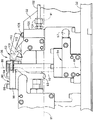
図2は、タービンブレード10を製造のために定位置に固定する固定具組立体50の側面図である。固定具組立体50は、製造プロセスのために用いられる固定具52と、該固定具52に連結されたダブテールクランプ組立体54と、該固定具52に連結された先端シュラウドクランプ組立体56とを含む。ダブテールクランプ組立体54及び先端シュラウドクランプ組立体56は、任意の適切な連結手段を用いて、固定具52に連結される。例えば、一実施形態において、少なくとも1つのダブテールクランプ組立体54及び先端シュラウドクランプ組立体56は、ネジ付きボルトとネジ付きナットとを用いて、固定具52に連結される。別の実施形態において、少なくとも1つのダブテールクランプ組立体54及び先端シュラウドクランプ組立体56は、ネジ付きボルトと固定具52内のネジ付き開口部とを用いて、該固定具52に連結される。製造プロセスを行う前に、鋳造タービンブレード10が固定具組立体50の中に垂直に搭載される。
FIG. 2 is a side view of a fixture assembly 50 that secures the
ダブテールクランプ組立体54は、ブレードのダブテール部14(図1に示す)が固定具52に対してブレード10の正確な製造が行われる位置に固定されるように、該ダブテール部14を位置合わせする。先端シュラウドクランプ組立体56は、ブレードの先端シュラウド28が固定具52に対してブレード10の正確な製造が行われる位置に維持されるように、該先端シュラウドを配置する。したがって、ダブテールクランプ組立体54及び先端シュラウドクランプ組立体56を用いることで、固定具組立体50が、固定具52に対して該ブレードの正確な製造が実現される位置にブレード10を配置し、取り付け及び保持することを容易にする。
The
図3は、ダブテールクランプ組立体54の斜視図である。ダブテールクランプ組立体54は、第1クランプ部材58と、第2クランプ部材60と、付勢機構62とを含む。図4は、図3の線4−4に沿って取ったダブテール第2クランプ部材の断面図であり、クランプ部材60を非クランプ位置で示している。第1クランプ部材58は、ダブテールクランプ組立体54に固定的に連結されて、該第1クランプ部材58が固定具52に対して動かないようにされる。より具体的には、第1クランプ部材58を、任意の適切な連結手段を用いて、ダブテールクランプ組立体54に固定的に連結する。例えば、一実施形態においては、第1クランプ部材58は、ネジ付きボルト及びネジ付きナットを用いて、ダブテールクランプ組立体54に連結される。別の実施形態においては、第1クランプ部材58は、ネジ付きボルト及びダブテールクランプ組立体54内のネジ付き穴を用いて、該ダブテールクランプ組立体54に連結される。
FIG. 3 is a perspective view of the
第2クランプ部材60は固定具52に回転可能に連結されて、該第2クランプ部材60が該固定具52に対して、回転軸64の周りで回転するようにされる。より具体的には、以下でより詳細に述べられるように、第2クランプ部材60は、回転軸64の周りに、「クランプ」位置(図5に示す)と「非クランプ」位置(図4に示す)との間で回転する。第2クランプ部材60は、任意の適切な手段を用いて、「クランプ」位置と「非クランプ」位置との間で回転させられる。例えば、図2ないし図5に示される例示的な実施形態において、第2クランプ部材60は、固定具組立体50の外側にある源から油圧流体供給ライン66及び供給ライン取付具67を介して供給される油圧流体を用いて駆動される。第2クランプ部材60が「クランプ」位置にあるとき、第1クランプ部材58及び第2クランプ部材60は、ダブテール部14を、ブレード10の正確な製造を実現する位置に固定的に取り付ける。
The
例示的な実施形態において、第2クランプ部材60は、任意の適切な方法で該第2クランプ部材に連結されたピン69を含む。ピン69は、任意の適切な方法によりダブテールクランプ組立体54、或いは固定具52に連結された第2クランプ付勢機構(図示せず)に連結される。第2クランプ付勢機構は、ピン69が軸64の周りで、第1クランプ部材58から離れる方向に回転するように該ピンを付勢する。ピン69及び第2クランプ付勢機構は、したがって、第2クランプ部材60が「クランプ」位置から「非クランプ」位置に回転するように該第2クランプ部材の付勢を助長する。代替的な実施形態においては、第2クランプ部材60はピン69を含まず、第2クランプ付勢機構が、該第2クランプ部材60を「クランプ」位置から「非クランプ」位置に直接付勢する。一実施形態において、第2クランプ付勢機構はばねである。
In the exemplary embodiment,
例示的な実施形態において、第2クランプ部材60は、さらに、該第2クランプ部材60を軸64に沿って貫通する半円筒形の開口部68を含み、ダブテールクランプ組立体54は、該ダブテールクランプ組立体54の表面72から外向きに該軸64の一部に沿って延びる半円筒形の突起70を含む。半円筒形の突起70は、表面72から延びるステム部分74と、該ステム部分74から延びる円筒形の部分76とを含む。円筒形の部分76は、半円筒形の開口部68内に受けられて、第2クランプ部材60が半円筒形の突起70により支持されるようになる。円筒形の部分76の直径d1は、半円筒形の開口部68の直径d2よりわずかに小さく、第2クランプ部材60が半円筒形の突起70及び軸64の周りを自由に回転できるようにされる。一実施形態において、直径d1は、直径d2より0.2インチ小さい。代替的な実施形態において(図示せず)、軸受(図示せず)が半円筒形の突起70と半円筒形の開口部68との間に位置させられて、第2クランプ部材60が該半円筒形の突起70及び軸64の周りで回転することを可能にする。第2クランプ部材60は、ここでは、例示的な方法でダブテールクランプ組立体54に回転可能に連結されるように図示され説明されているが、第2クランプ部材60を、任意の適切な方法で該ダブテールクランプ組立体54に回転可能に連結することができることは、理解されるであろう。例えば、代替的な実施形態において(図示せず)、第2クランプ部材60を、ダブテールクランプ組立体54と回転可能に連結されたロッド(図示せず)により、固定的に連結することができる。
In the exemplary embodiment, the
ここで述べられる例示的な実施形態において上述され、図2ないし図5に示されるように、第2クランプ部材60の「クランプ」位置と「非クランプ」位置との間の回転は、油圧流体により駆動される。より具体的には、ダブテールクランプ組立体54は、入口ポート80と、内部チャンバ(図示せず)と、ロッド82とを含む油圧シリンダ78を含む。入口ポート80は内部チャンバと流体連通し、かつ入口ポート供給ライン84と流体連通するように連結されており、入口ポート供給ラインは、供給ライン取付具67と流体連通するように連結される。供給ライン取付具67は、油圧流体供給ライン66と流体連通するように連結され、油圧流体供給ラインは、固定具組立体50の外側の油圧流体源と流体連通するように連結される。油圧シリンダ78の内部チャンバは、油圧シリンダ78の内部チャンバ内で、油圧シリンダ78の中心軸86に沿って摺動可能なピストン(図示せず)を含む。ロッド82がピストンに連結され、油圧シリンダの内部チャンバの一部から外方へ貫通し、油圧シリンダ78の開口部88を通って、第2クランプ部材60まで延びる。開口部88は、ロッド82と該開口部88との間を周方向に延びるシーリング手段(図示せず)を含み、これは油圧シリンダ78の内部チャンバのシーリングを助ける。ロッド82は、開口部88内で中心軸86に沿って移動可能である。
As described above in the exemplary embodiment described herein and illustrated in FIGS. 2-5, rotation of the
油圧シリンダ78の内部チャンバ内の油圧流体に圧力がかけられると、ピストンは、中心軸86に沿って第2クランプ部材60の方向に摺動し、これによりロッド82が開口部88を通り中心軸86に沿って、第2クランプ部材60の方向に移動するようになる。ロッド82が中心軸86に沿ってある距離を移動すると、ロッド82は第2クランプ部材60に接触し、ロッド82の中心軸86に沿った第2クランプ部材60の方向への移動を続けることにより、第2クランプ部材60が軸64の周りで、「非クランプ」位置から「クランプ」位置まで回転するようになる。油圧シリンダ78の内部チャンバから圧力が取り除かれると、開口部88内のロッド82の移動に起因する開口部88のためのシーリング手段の変形が該ロッド82を付勢して、開口部88内で中心軸86に沿って第2クランプ部材60から離れる方向に移動させる。さらに、第2クランプ付勢機構は、ピン69が軸64の周りで第1クランプ部材58から離れる方向に回転するように該ピンを付勢し、これにより第2クランプ部材60が軸64の周りで第1クランプ部材58から離れる方向に回転するようになる。したがって、油圧シリンダ78の内部チャンバ内の油圧流体から圧力が取り除かれると、第2クランプ部材60は、軸64の周りで、「クランプ」位置から「非クランプ」位置に回転するようになる。
When pressure is applied to the hydraulic fluid in the internal chamber of the
付勢機構62は、任意の適切な連結手段を用いてダブテールクランプ組立体54に固定的に連結される。一実施形態において、付勢機構62は、ネジ付きボルト及びネジ付きナットを用いてダブテールクランプ組立体54に連結される。別の実施形態において、付勢機構62は、ネジ付きボルト及びダブテールクランプ組立体54内のネジ付き穴を用いて連結される。ダブテール部14の少なくとも一部が付勢機構62の一部の中に受けられる。さらに、ダブテール部14の少なくとも一部が第1クランプ部材58の一部の中に受けられる。
The
ブレード10が固定具組立体50の中に軸89に沿って搭載される。ブレード10は、固定具組立体50の中に、軸89に垂直な軸91ではなく該軸89に沿って搭載されるため、中心軸64に沿ったロッド82の移動量を少なく維持することができる。ブレード10が固定具組立体50の中に搭載されると、ダブテール部14がダブテールクランプ組立体54内に受けられる。付勢機構62が変形して、ダブテール部14の一部が該付勢機構62の一部の中及び第1クランプ部材58の一部の中に受けられるようにする。ダブテール部14が付勢機構62内及び第1クランプ部材58内に受けられた後、該付勢機構62は該ダブテール部14を該第1クランプ部材58に対して付勢し、これにより該ダブテール部14が該第1クランプ部材58に対して固定されるようになる。ダブテール部14を第1クランプ部材58に対して固定することにより、付勢機構62が、該ダブテール部14を該第1クランプ部材58に対し摩擦的に連結させ、第2クランプ部材60によるクランプの前に、該付勢機構62の付勢のもとでダブテール部14が第1クランプ部材58に対して定位置に留まるようにする。
The
第1クランプ部材58に対して固定されたとき、付勢機構62は、ダブテール部14をブレード10の正確な製造が行われる位置に付勢し、第2クランプ部材が「非クランプ」位置にある間、該ダブテール部14をその位置に保持する。ダブテール部14が第1クランプ部材58に固定されると、第2クランプ部材60が「クランプ」位置に回転されて、該ダブテール部14をブレード10の製造のための定位置に固定的に取り付ける。
When fixed relative to the
付勢機構62は、ここでは例示的な方法で説明され図示されているが、該付勢機構62は、ダブテール部14を第1クランプ部材58に対して固定して、それによりブレード10の正確な製造が行われる位置にダブテール部14を位置合わせし、さらに第2クランプ部材が「非クランプ」位置にある間、ブレード10の正確な製造が行われる位置にダブテール部14を保持するような他のどのような適切な形状及び/又は形式の付勢機構であってもよいことが理解されるであろう。一実施形態において、付勢機構62はばねである。例えば、一実施形態において、付勢機構62はコイルばねである。別の実施形態において、付勢機構62は板ばねである。さらに別の実施形態において、付勢機構62は重ね板ばねである。
Although the
図5は、「クランプ」位置にあるダブテール第2クランプ部材60の断面図である。ブレード10の正確な製造を行わせるために、第2クランプ部材60が「非クランプ」位置(図4に示す)から「クランプ」位置(図5に示す)に回転されると同時に、ダブテール部14は、付勢機構62により第1クランプ部材58に対して固定される。一実施形態において、第2クランプ部材60の一部の形状は、ダブテール部14の外形に相補的な関係にあり、該ダブテール部14の少なくとも一部が該第2クランプ部材60の一部の中に受けられる。上述のように、油圧シリンダ78の内部チャンバに圧力がかけられると、ロッド82の作動が、第2クランプ部材60を「非クランプ」位置から「クランプ」位置に回転させる。
FIG. 5 is a cross-sectional view of the dovetail
第2クランプ部材60が「クランプ」位置にあるときには、ダブテール部14は第1クランプ部材58及び第2クランプ部材60と摩擦的に連結されて、該第2クランプ部材が「クランプ」位置にある間は、該ダブテール部14は該第1クランプ部材58、該第2クランプ部材60、及び固定具52に対して定位置に保持される。ダブテール部14の外形に対して相補的な形状にされた第2クランプ部材60の一部及び第1クランプ部材58の一部は、該ダブテール部14が該第2クランプ部材60内及び該第1クランプ部材58内に受けられたとき、該ダブテール部14が、該第1クランプ部材58と該第2クランプ部材60との間において、固定具52に対して定位置に固定的に取り付けられるように構成され、これによりブレード10の正確な製造が行われるようになる。より具体的には、第2クランプ部材60が「クランプ」位置にある間に、第1クランプ部材58及び該第2クランプ部材60によりダブテール14にかけられた力は、ブレード10の外形及び/又は形態を歪めることなく、該ブレード10の正確な製造が行われる定位置にダブテール部14を維持するのに十分である。
When the
再び図2を参照すると、先端シュラウドクランプ組立体56は、部品ロケータ90と、ここでは第3クランプ部材92と呼ばれるクランプ部材92と、該先端シュラウドクランプ組立体56に連結されたシュラウド作動支持レバー93とを含む。シュラウド作動支持レバー93は、ブレード10の製造中に該ブレード10の支持を助ける。部品ロケータ90は、該部品ロケータ90の表面96に複数の溝(図5には示されない)を含む冷却媒体ガイド94を含む。冷却媒体ガイド94は、ブレード10の製造中に、冷却媒体を冷却媒体源(図示せず)から該ブレード10に導く。代替的な実施形態において、冷却媒体ガイド94は、部品ロケータ90の本体98を貫通する複数の通路を含む。冷却媒体ガイド94は、該冷却媒体ガイド94がブレード10の製造中に冷却媒体を該ブレード10に導くように任意の方法で構成することができることが理解されるであろう。
Referring again to FIG. 2, the tip
部品ロケータ90は、該部品ロケータ90が固定具52に対して移動しないように、先端シュラウドクランプ組立体56に固定的に連結される。部品ロケータ90は、任意の適切な連結手段を用いて先端シュラウドクランプ組立体56に連結される。一実施形態において、部品ロケータ90は、ネジ付きボルト及びネジ付きナットを用いて先端シュラウドクランプ組立体56に連結される。別の実施形態において、部品ロケータ90は、ネジ付きボルト及び先端シュラウドクランプ組立体56におけるネジ付き穴を用いて、該先端シュラウドクランプ組立体56に連結される。部品ロケータ90の一部116(図6に示す)は、ブレード10の先端シュラウド28の外形に相補的に形成されて、該ブレード10の先端シュラウド28の少なくとも一部が該部品ロケータ90内に受けられるようにする。
The
第3クランプ部材92は、固定具52に回転可能に連結されており、該第3クランプ部材92が、固定具52に対して回転軸100の周りを「クランプ」位置(図2に示す)と「非クランプ」位置(図示せず)との間で回転するようになる。第3クランプ部材92が「クランプ」位置にあるとき、部品ロケータ90及び第3クランプ部材92は、ブレード10の製造中に、該ブレード10の正確な製造が行われる位置にブレードの先端シュラウドを固定的に取り付ける。例示的な実施形態において、第3クランプ部材92は、任意の適切な方法により第3クランプ部材に連結されたピン101を含む。ピン101は、任意の適切な方法により先端シュラウドクランプ組立体54或いは固定具52に連結された第3クランプ部材付勢機構(図示せず)と係合する。第3クランプ部材付勢機構は、ピン101が、軸100の周りで部品ロケータ90から離れる方向に回転するように該ピンを付勢する。ピン101及び第3クランプ部材付勢機構は、このように、第3クランプ部材92が「クランプ」位置から「非クランプ」位置に回転するように、第3クランプ部材を付勢することを助ける。代替的な実施形態において、第3クランプ部材92はピン101を含まず、第3クランプ部材付勢機構は、該第3クランプ部材92を「クランプ」位置から「非クランプ」位置に直接付勢する。一実施形態において、第3クランプ部材付勢機構はばねである。
The
「クランプ」位置と「非クランプ」位置との間の第3クランプ部材92の回転は、任意の適切な手段によって駆動される。例えば、図5に示され、ここで説明される例示的な実施形態において、第3クランプ部材92は、固定具組立体50の外側にある源から油圧流体供給ライン102及び供給ライン取付具104を通り、油圧シリンダ106に供給された油圧流体により駆動される。先端シュラウド組立体56は、油圧シリンダ106の内部チャンバ(図示せず)内のピストン(図示せず)に連結されたロッド108を含む。第3クランプ部材92を軸100の周りに回転させるように作動する油圧シリンダ106の作動は、油圧シリンダ78による第2クランプ部材60の作動とほぼ同様である。より具体的には、油圧シリンダ106の内部チャンバ内の油圧流体に圧力がかけられると、ロッド108は、第3クランプ部材92を、軸100の周りで、「非クランプ」位置から「クランプ」位置に回転させる。油圧シリンダ106の内部チャンバから圧力が取り除かれると、ロッド108は第3クランプ部材92から離れる方向に付勢され、第3クランプ部材付勢機構は、ピン101が、軸100の周りで部品ロケータ90から離れる方向に回転するように該ピンを付勢し、これにより、第3クランプ部材92が、軸100の周りで部品ロケータ90から離れる方向に回転するようになる。したがって、油圧シリンダ106の内部チャンバ内の油圧流体から圧力が取り除かれると、第3クランプ部材92は軸100の周りで、「クランプ」位置から「非クランプ」位置に回転されるようになる。
The rotation of the
例示的な実施形態において、第3クランプ部材92は、軸100に沿って該第3クランプ部材92を貫通する半円筒形の開口部110を含み、先端シュラウドクランプ組立体56は、該シュラウドクランプ組立体56の表面114から外向きに、軸100の一部に沿って延びる半円筒形の突起112を含む。半円筒形の突起112は、表面114から延び、半円筒形の開口部110内に受けられて、第3クランプ部材92が該半円筒形の突起112により支持されるようなる。半円筒形の突起112の直径は、半円筒形の開口部110の直径よりわずかに小さく、第3クランプ部材92が該半円筒形の突起112及び軸100の周りを自由に回転できるようにされる。一実施形態において、半円筒形の突起112の直径は、半円筒形の開口部110の直径より0.2インチ小さい。代替的な実施形態において(図示せず)、軸受(図示せず)が半円筒形の突起112と半円筒形の開口部110との間に位置させられて、第3クランプ部材92が該半円筒形の突起112及び軸100の周りで回転するのを助ける。第3クランプ部材92は、ここでは例示的な方法により、先端シュラウドクランプ組立体56に回転可能に連結されるように図示及び説明されているが、該第3クランプ部材92を、任意の適切な方法により、先端シュラウドクランプ組立体56に回転可能に連結することができることが理解されるであろう。
In the exemplary embodiment, the
図6は、冷却媒体ガイド94及び先端シュラウド部分116を含む部品ロケータ90の斜視図である。先端シュラウド部分116は、ブレードの先端シュラウド28の外形に対応して形成されて、該ブレードの先端シュラウド28が部品ロケータ90に対して取り付けられたとき、該先端シュラウド28は、固定具52に対して、ブレード10の正確な製造が行われる位置になる。一実施形態において、第3クランプ部材92の一部(図示せず)の形状は、ブレードの先端シュラウド28の外形に相補的な関係にあり、ブレードの先端シュラウドの少なくとも一部が、第3クランプ部材92の一部の中に受けられるようにされる。
FIG. 6 is a perspective view of a
ブレード10が固定具組立体50の中に軸89に沿って搭載される。ブレード10は、固定具組立体50の中に、軸89に垂直な軸91ではなく、該軸89に沿って搭載されるため、軸100に沿ったロッド108の移動量を少なく維持することができる。ブレード10が固定具組立体50に搭載されたとき、該ブレード10のブレード先端シュラウドが先端シュラウドクランプ組立体56内に受けられ、ダブテールクランプ組立体54が、固定具52に対してブレード10の正確な製造が行われる位置にダブテール部14を固定的に取り付ける。ブレード10が先端シュラウドクランプ組立体56の中に搭載されると、部品ロケータ90が、先端シュラウド28を、ブレード10の正確な製造が行われる位置に位置決めする。ブレード10のブレード先端シュラウドが部品ロケータ90により位置決めされた後、第3クランプ部材92が「非クランプ」位置から「クランプ」位置に回転されて、ブレード先端シュラウドを、該ブレード10の正確な製造が行われる定位置に固定的に取り付けるようになる。一実施形態においては、第2クランプ部材60は、第3クランプ部材92より前に、「クランプ」位置に回転される。別の実施形態においては、第3クランプ部材92は、第2クランプ部材60より前に「クランプ」位置に回転させられる。さらに別の実施形態においては、第3クランプ部材92及び第2クランプ部材60は、ほぼ同時に「クランプ」位置に回転される。
The
上述のように、ロッド108の作動は、第3クランプ部材92を「非クランプ」位置から「クランプ」位置に回転させる。第3クランプ部材92が「クランプ」位置にあるとき、先端シュラウド28は部品ロケータ90及び第3クランプ部材92と摩擦的に連結され、ブレード10の先端シュラウド28が、製造中に、部品ロケータ90、第3クランプ部材92、及び固定具52に対して定位置に留まるようにされる。ブレード10の先端シュラウド28の外形に対して相補的に形成された部品ロケータ90及びクランプ部材92の各部分は、該部品ロケータ90及び第3クランプ部材92のそれぞれに相補的に形成された部分の中に受けられる。さらに、製造中、シュラウド作動支持レバー93は、先端シュラウド28の底面30(図1に示す)に接触する。シュラウド作動支持レバー93は、底面30を支持することにより、ブレード10の正確な製造が行われる位置に先端シュラウド28を固定的に取り付けることを容易にする。より具体的には、シュラウド作動支持レバー93が、製造中に底面30を支持することにより、先端シュラウド28が曲がらないようにし、したがって、ブレード10の外形及び/又は形態を歪ませないようにする。
As described above, actuation of the
一実施形態において、先端シュラウド28は、該先端シュラウド28の外形を機械加工するために、クリープフィード研削盤を用いて製造される。先端シュラウドの外形が研削プロセスを用いて機械加工されるため、潤滑冷却媒体が、研削表面(図示せず)と研削されている先端シュラウド28の表面(図示せず)との間に導かれる。冷却媒体溝118は、冷却媒体の流れを固定具組立体50から研削表面と研削されている先端シュラウド28の表面との間のブレード10に導く。冷却媒体ガイド94は、ここでは冷却媒体溝118を含むように図示され説明されているが、該冷却媒体ガイド94は、例えば、ブレード10の製造中に、該冷却媒体ガイド94が研削表面と研削されている先端シュラウド28の表面との間のブレード10に冷却媒体を導く機能及び構造を含むように任意の方法で構成することができる。研削プロセスが完了すると圧力が取り除かれ、第3クランプ部材92が軸100の周りで、「クランプ」位置から「非クランプ」位置に回転されるようになる。
In one embodiment, the
固定具組立体50は、ブレード10の外形及び/又は形態を歪めることなく、製造されている表面に冷却媒体を供給しながら、製造中に該ブレード10を該ブレードの正確な製造が行われる位置に固定的に取り付ける。さらに、固定具組立体50は、ダブテール部14及び先端シュラウド28を含むブレード10を該ブレード10の正確な製造が行われる位置にオペレータからの最小の入力で位置合わせする。
The fixture assembly 50 is a position where the
上述の工具は費用効率が良く、製造中に部品を固定することに関して信頼性が高い。この工具は、ブレードのダブテール部及び先端シュラウドを製造中に固定することを可能にする。より具体的には、この工具は、ブレードの外形及び/又は形態を歪めることなく、該ブレードのダブテール部及び先端シュラウドを定位置に堅固に固定する。該工具は、さらに、製造中に、多数の機械、固定具及び/又はプロセスを用いることなく、ブレードのダブテール部及び先端シュラウドを固定することを容易にすることができる。ブレードは、一旦工具に連結されると自己配向することができるので、該工具は、オペレータからの最小の入力しか要求しない。その結果、該工具は、費用効率が良く信頼性のある方法で、製造費用を削減することを助長する。 The tools described above are cost effective and reliable with respect to securing parts during manufacture. This tool allows the blade dovetail and tip shroud to be secured during manufacture. More specifically, the tool securely fixes the blade dovetail and tip shroud in place without distorting the blade profile and / or configuration. The tool may further facilitate securing the blade dovetail and tip shroud during manufacture without using multiple machines, fixtures and / or processes. Since the blade can self-orient once connected to the tool, the tool requires minimal input from the operator. As a result, the tool helps reduce manufacturing costs in a cost-effective and reliable manner.
工具組立体の例示的な実施形態が詳細に上述されている。システムは、ここで説明された特定の実施形態に限定されるものではなく、むしろ各組立体の部品を、ここで説明された他の部品とは独立して別個に利用することができる。また、各々の工具組立体を、他の工具組立体の部品と組み合わせて用いることができる。 Exemplary embodiments of tool assemblies are described above in detail. The system is not limited to the specific embodiments described herein, but rather the components of each assembly can be utilized separately and independently of the other components described herein. Also, each tool assembly can be used in combination with parts of other tool assemblies.
本発明は、種々の特定の実施形態に関して説明されたが、当業者であれば、本発明を特許請求の範囲の思想及び範囲内にある修正形態と併せて実施することができることを理解するであろう。なお、特許請求の範囲に記載された符号は、理解容易のためであってなんら発明の技術的範囲を実施例に限縮するものではない。 While the invention has been described in terms of various specific embodiments, those skilled in the art will recognize that the invention can be practiced in conjunction with modifications that are within the spirit and scope of the claims. I will. In addition, the code | symbol described in the claim is for easy understanding, and does not limit the technical scope of an invention to an Example at all.
10 部品、ブレード
50 工具
52 固定具
58 第1クランプ部材
60 第2クランプ部材
62 付勢機構
90 部品ロケータ
92 クランプ部材
94 冷却媒体ガイド
118 溝
106 油圧シリンダ
DESCRIPTION OF
Claims (10)
固定具(52)と、
前記固定具に固定的に連結された部品ロケータ(90)と、
を備え、
前記部品ロケータ(90)は、前記第1の端部(28)と相補的な形状を有し、前記部品を前記固定具に対して所定の定位置とするために該部品(10)を前記工具(50)内に位置させ、
前記部品ロケータ(90)は、該部品ロケータ(90)を横切って延びる少なくとも1つの溝(118)を備える少なくとも1つの冷却媒体ガイド(94)を備えて前記部品の製造中に、冷却媒体を前記部品に通し、
前記工具は、前記固定具に連結された第3クランプ部材(92)を更に備え、
前記部品ロケータと前記クランプ部材とがそれらの間に前記部品を保持するように構成されており、
前記工具は、クランプ組立体(54)をさらに備え、
該クランプ組立体(54)は、前記固定具に固定された第1のクランプ部材(58)と、前記固定具に回転可能に取り付けられた第2のクランプ部材(60)とを備え、該第1及び第2のクランプ部材の間に前記部品の第2の端部(14)を固定する
ことを特徴とする工具(50)。 A tool (50) for fixing a component (10) comprising a first end (28) and a second end (14),
A fixture (52);
A component locator (90) fixedly coupled to the fixture;
With
The component locator (90) has a shape complementary to the first end (28), and the component (10) is placed in the predetermined position with respect to the fixture. Located in the tool ( 50 ),
The part locator (90) comprises at least one cooling medium guide (94) comprising at least one groove (118) extending across the part locator (90) to allow the cooling medium to pass during manufacture of the part. Through the parts,
The tool further comprises a third clamp member (92) connected to the fixture,
The component locator and the clamp member are configured to hold the component between them;
The tool further comprises a clamp assembly (54),
The clamp assembly (54) includes a first clamp member (58) fixed to the fixture, and a second clamp member (60) rotatably attached to the fixture. Tool (50), characterized in that the second end (14) of the part is fixed between the first and second clamping members.
前記第1の端部(28)が、底面(30)を備える先端シュラウドであり、前記第2の端部(14)がダブテール部であり、
前記工具は、前記先端シュラウドの前記底面(30)に接触して該底面を支持するシュラウド作動支持レバー(93)をさらに備えることを特徴とする請求項1乃至5のいずれか1項に記載の工具(50)。 Said part (10) is a turbine blade;
The first end (28) is a tip shroud with a bottom surface (30), and the second end (14) is a dovetail portion;
The said tool is further equipped with the shroud action | operation support lever (93) which contacts the said bottom face (30) of the said front-end | tip shroud, and supports this bottom face, The one of Claim 1 thru | or 5 characterized by the above-mentioned. Tool (50).
固定具(52)と、
前記固定具に固定的に連結された部品ロケータ(90)と、
を備え、
前記部品ロケータ(90)は、前記第1の端部(28)と相補的な形状を有し、前記部品を前記固定具に対して所定の定位置とするために該部品(10)を前記工具(50)内に位置させ、
前記装置は、前記固定具に連結された第3クランプ部材(92)を更に備え、
前記部品ロケータと前記クランプ部材とがそれらの間に前記部品を保持するように構成されており、
前記装置は、クランプ組立体(54)をさらに備え、
該クランプ組立体(54)は、前記固定具に固定された第1のクランプ部材(58)と、前記固定具に回転可能に取り付けられた第2のクランプ部材(60)とを備え、該第1及び第2のクランプ部材の間に前記部品の第2の端部(14)を固定する
ことを特徴とする装置(50)。 A device (50) for securing a part (10) comprising a first end (28) and a second end (14) for manufacturing,
A fixture (52);
A component locator (90) fixedly coupled to the fixture;
With
The component locator (90) has a shape complementary to the first end (28), and the component (10) is placed in the predetermined position with respect to the fixture. Located in the tool ( 50 ),
The apparatus further comprises a third clamping member (92) coupled to the fixture.
The component locator and the clamp member are configured to hold the component between them;
The apparatus further comprises a clamp assembly (54),
The clamp assembly (54) includes a first clamp member (58) fixed to the fixture, and a second clamp member (60) rotatably attached to the fixture. A device (50), characterized in that the second end (14) of the part is fixed between the first and second clamping members.
Applications Claiming Priority (1)
| Application Number | Priority Date | Filing Date | Title |
|---|---|---|---|
| US10/253,869 US7219408B2 (en) | 2002-09-24 | 2002-09-24 | Tool for securing a component |
Publications (3)
| Publication Number | Publication Date |
|---|---|
| JP2004114293A JP2004114293A (en) | 2004-04-15 |
| JP2004114293A5 JP2004114293A5 (en) | 2006-11-09 |
| JP4656828B2 true JP4656828B2 (en) | 2011-03-23 |
Family
ID=31977811
Family Applications (1)
| Application Number | Title | Priority Date | Filing Date |
|---|---|---|---|
| JP2003330962A Expired - Fee Related JP4656828B2 (en) | 2002-09-24 | 2003-09-24 | Method and apparatus for securing parts for manufacturing |
Country Status (3)
| Country | Link |
|---|---|
| US (2) | US7219408B2 (en) |
| EP (1) | EP1403003B1 (en) |
| JP (1) | JP4656828B2 (en) |
Families Citing this family (17)
| Publication number | Priority date | Publication date | Assignee | Title |
|---|---|---|---|---|
| US7334331B2 (en) * | 2003-12-18 | 2008-02-26 | General Electric Company | Methods and apparatus for machining components |
| US7966713B2 (en) * | 2006-05-17 | 2011-06-28 | The Boeing Company | Tooling head mounted structural positioning |
| DE102007011729B4 (en) * | 2007-03-10 | 2018-08-16 | MTU Aero Engines AG | Method and device for processing components of a gas turbine |
| US8151458B2 (en) * | 2008-02-21 | 2012-04-10 | United Technologies Corporation | Non-metallic cover for a fixture |
| KR101078551B1 (en) | 2010-02-18 | 2011-11-01 | 두산중공업 주식회사 | Jig in order to do clamp to dummy of bucket |
| GB201102799D0 (en) * | 2011-02-18 | 2011-04-06 | Rolls Royce Plc | Apparatus for immobilising a component during a machining operation |
| CN102975061B (en) * | 2012-10-08 | 2015-06-17 | 清华大学 | Precision machining technological equipment and machining method for blade of aviation engine |
| CN103028962A (en) * | 2012-11-30 | 2013-04-10 | 无锡透平叶片有限公司 | Method for improving positioning accuracy of blade and blade root of tenon tooth |
| US20140339751A1 (en) * | 2013-05-14 | 2014-11-20 | Asti Global Optoelectronics (Suzhou) LTD | Fixture for clamping workpiece |
| CN103846706B (en) * | 2014-03-20 | 2016-04-20 | 西北工业大学 | The special stretching device of a kind of blade parts milling |
| CN104190904A (en) * | 2014-08-01 | 2014-12-10 | 南京赛达机械制造有限公司 | Fixture special for steam turbine die forging blades |
| US10105804B2 (en) * | 2014-10-15 | 2018-10-23 | United Technologies Corporation | Fixture system and method for securing an airfoil during material removal operations |
| CN105415020B (en) * | 2016-01-22 | 2018-08-10 | 沈阳黎明航空发动机(集团)有限责任公司 | A kind of dismountable blade fixture of positioning surface |
| US10814445B2 (en) | 2016-05-09 | 2020-10-27 | Raytheon Technologies Corporation | Airfoil machining |
| JP6747946B2 (en) * | 2016-11-25 | 2020-08-26 | 三菱日立パワーシステムズ株式会社 | Electric discharge machining method and electric discharge machine |
| US10415403B2 (en) * | 2017-01-13 | 2019-09-17 | Rolls-Royce North American Technologies Inc. | Cooled blisk for gas turbine engine |
| CN114193186B (en) * | 2021-12-17 | 2023-03-14 | 成都市鸿侠科技有限责任公司 | Numerical control machining process and tool for split blade of aircraft engine |
Citations (4)
| Publication number | Priority date | Publication date | Assignee | Title |
|---|---|---|---|---|
| US3331166A (en) * | 1964-11-27 | 1967-07-18 | Brenning Albert | Jig for grinding turbine blades of jet engines |
| JP2000176766A (en) * | 1998-12-17 | 2000-06-27 | United Technol Corp <Utc> | Fitting tool for holding blank member and fitting method for blank member |
| US6231035B1 (en) * | 1999-11-03 | 2001-05-15 | General Electric Company | Workpiece fixture |
| JP2002277355A (en) * | 2001-01-09 | 2002-09-25 | General Electric Co <Ge> | Testing device for water flow |
Family Cites Families (25)
| Publication number | Priority date | Publication date | Assignee | Title |
|---|---|---|---|---|
| DE2538737C2 (en) | 1975-08-30 | 1985-02-28 | Michael Weinig Kg, 6972 Tauberbischofsheim | Tool grinding machine for profile tools |
| US4128929A (en) * | 1977-03-15 | 1978-12-12 | Demusis Ralph T | Method of restoring worn turbine components |
| US4142332A (en) | 1977-10-03 | 1979-03-06 | Clarke Edmond C | Drill grinding fixture |
| US4455787A (en) | 1981-11-02 | 1984-06-26 | United Technologies Corporation | Engine fan case grinder |
| US4607460A (en) * | 1985-04-18 | 1986-08-26 | Hauni-Werke Korber & Co. Kg | Grinding machine with a reciprocable column for work supporting devices |
| US4796877A (en) * | 1988-03-07 | 1989-01-10 | Crawford Fitting Company | Workpiece holder and saw guide device |
| DE8902380U1 (en) | 1989-03-01 | 1989-04-20 | Jankus, Werner, 4600 Dortmund, De | |
| US5097634A (en) | 1989-12-08 | 1992-03-24 | Hulme Jack R | Tool grinder apparatus and method |
| DE4129402A1 (en) * | 1991-09-04 | 1993-03-11 | Blohm Maschinenbau Gmbh | COOLING DEVICE FOR A GRINDING MACHINE |
| US5288209A (en) * | 1991-12-19 | 1994-02-22 | General Electric Company | Automatic adaptive sculptured machining |
| US5191711A (en) * | 1991-12-23 | 1993-03-09 | Allied-Signal Inc. | Compressor or turbine blade manufacture |
| US5494408A (en) | 1994-10-12 | 1996-02-27 | General Electric Co. | Bucket to wheel dovetail design for turbine rotors |
| US6186867B1 (en) * | 1996-04-30 | 2001-02-13 | United Technologies Corporation | Method for manufacturing precisely shaped parts |
| US6139412A (en) * | 1996-04-30 | 2000-10-31 | United Technologies Corporation | Fixture for manufacturing precisely shaped parts |
| US6017263A (en) * | 1996-04-30 | 2000-01-25 | United Technologies Corporation | Method for manufacturing precisely shaped parts |
| US6068541A (en) * | 1997-12-22 | 2000-05-30 | United Technologies Corporation | Method for using a fixture enabling more accurate machining of a part |
| JP2001009720A (en) * | 1999-06-22 | 2001-01-16 | Hitachi Seiki Co Ltd | Coolant supply method and device for grinding machine |
| US6237907B1 (en) | 1999-08-09 | 2001-05-29 | Joseph W. Lawrence | Method and apparatus for machining a radius or diameter feature at non symmetrical locations on a workpiece |
| US6065744A (en) | 1999-08-09 | 2000-05-23 | Lawrence; Joseph W. | Work holder precisely adjustable jaws |
| US6844515B2 (en) * | 2001-10-10 | 2005-01-18 | Brett Wayne Byrnes | Method and apparatus for turbine blade machining |
| US6652369B2 (en) * | 2001-12-13 | 2003-11-25 | General Electric Company | Fixture for clamping a gas turbine component and its use in shaping the gas turbine component |
| US6855033B2 (en) * | 2001-12-13 | 2005-02-15 | General Electric Company | Fixture for clamping a gas turbine component blank and its use in shaping the gas turbine component blank |
| US6821193B2 (en) * | 2002-03-27 | 2004-11-23 | Roger Kaye | Material positioning and shaping system apparatus |
| US6830240B2 (en) * | 2002-09-24 | 2004-12-14 | General Electric Company | Methods and apparatus for securing components for manufacture |
| US7761974B2 (en) * | 2005-01-19 | 2010-07-27 | Gm Global Technology Operations, Inc. | Reconfigurable fixture device and methods of use |
-
2002
- 2002-09-24 US US10/253,869 patent/US7219408B2/en not_active Expired - Fee Related
-
2003
- 2003-09-23 EP EP03255942.9A patent/EP1403003B1/en not_active Expired - Fee Related
- 2003-09-24 JP JP2003330962A patent/JP4656828B2/en not_active Expired - Fee Related
-
2007
- 2007-01-26 US US11/627,802 patent/US20070119040A1/en not_active Abandoned
Patent Citations (4)
| Publication number | Priority date | Publication date | Assignee | Title |
|---|---|---|---|---|
| US3331166A (en) * | 1964-11-27 | 1967-07-18 | Brenning Albert | Jig for grinding turbine blades of jet engines |
| JP2000176766A (en) * | 1998-12-17 | 2000-06-27 | United Technol Corp <Utc> | Fitting tool for holding blank member and fitting method for blank member |
| US6231035B1 (en) * | 1999-11-03 | 2001-05-15 | General Electric Company | Workpiece fixture |
| JP2002277355A (en) * | 2001-01-09 | 2002-09-25 | General Electric Co <Ge> | Testing device for water flow |
Also Published As
| Publication number | Publication date |
|---|---|
| JP2004114293A (en) | 2004-04-15 |
| EP1403003A3 (en) | 2008-12-03 |
| US7219408B2 (en) | 2007-05-22 |
| US20070119040A1 (en) | 2007-05-31 |
| US20040055134A1 (en) | 2004-03-25 |
| EP1403003B1 (en) | 2013-11-06 |
| EP1403003A2 (en) | 2004-03-31 |
Similar Documents
| Publication | Publication Date | Title |
|---|---|---|
| JP4572402B2 (en) | Method and apparatus for securing parts for manufacturing | |
| JP4656828B2 (en) | Method and apparatus for securing parts for manufacturing | |
| US7296331B2 (en) | Apparatus and method for centering a workpiece on a machine tool | |
| JP4698975B2 (en) | Fixing jig with integrated datum locator | |
| JP2007182875A (en) | Fixture, welding station, and method and device for processing blade | |
| CN201446257U (en) | Tension sleeve type numerical-control automatic jig | |
| US6994000B2 (en) | Fixture and locator device for supporting a rotatable member | |
| JPH06270002A (en) | Clamp connection device | |
| US20050249565A1 (en) | Method and device for chucking rotationally symmetrical bodies and configuration of the body to be chucked | |
| US9126272B2 (en) | Weld bead cutting device | |
| JP5295504B2 (en) | Method and apparatus for manufacturing components | |
| JP7053142B2 (en) | Portable mill tools and milling methods | |
| US5400491A (en) | Apparatus for repairing a combustion chamber assembly | |
| CN112935788B (en) | Butt joint guiding device of unit body with long shaft and technological method | |
| JP3213863U (en) | Processing machine support device and processing machine | |
| CN105798656A (en) | Positioning fixture for excircle machining of motor stator | |
| JP6767779B2 (en) | Chuck device and work chuck method | |
| JPS62166935A (en) | Support device for rotary tool | |
| CN218800475U (en) | Auxiliary supporting device for lathe | |
| CN213646688U (en) | Indexing positioning fixing device | |
| CN217045988U (en) | Grinding hole supporting clamp with spigot thin-wall gear | |
| CN210937553U (en) | High-precision and quick positioning tool for wire cutting | |
| JP2007276087A (en) | Spindle device | |
| CN117300651A (en) | Clamping device, machine tool, manufacturing apparatus and method for manufacturing a workpiece | |
| RU52753U1 (en) | BORING HEAD |
Legal Events
| Date | Code | Title | Description |
|---|---|---|---|
| A521 | Request for written amendment filed |
Free format text: JAPANESE INTERMEDIATE CODE: A523 Effective date: 20060921 |
|
| A621 | Written request for application examination |
Free format text: JAPANESE INTERMEDIATE CODE: A621 Effective date: 20060921 |
|
| A131 | Notification of reasons for refusal |
Free format text: JAPANESE INTERMEDIATE CODE: A131 Effective date: 20090602 |
|
| A601 | Written request for extension of time |
Free format text: JAPANESE INTERMEDIATE CODE: A601 Effective date: 20090831 |
|
| RD02 | Notification of acceptance of power of attorney |
Free format text: JAPANESE INTERMEDIATE CODE: A7422 Effective date: 20090831 |
|
| RD04 | Notification of resignation of power of attorney |
Free format text: JAPANESE INTERMEDIATE CODE: A7424 Effective date: 20090831 |
|
| A602 | Written permission of extension of time |
Free format text: JAPANESE INTERMEDIATE CODE: A602 Effective date: 20090903 |
|
| A521 | Request for written amendment filed |
Free format text: JAPANESE INTERMEDIATE CODE: A523 Effective date: 20091130 |
|
| A131 | Notification of reasons for refusal |
Free format text: JAPANESE INTERMEDIATE CODE: A131 Effective date: 20100706 |
|
| A521 | Request for written amendment filed |
Free format text: JAPANESE INTERMEDIATE CODE: A523 Effective date: 20100930 |
|
| TRDD | Decision of grant or rejection written | ||
| A01 | Written decision to grant a patent or to grant a registration (utility model) |
Free format text: JAPANESE INTERMEDIATE CODE: A01 Effective date: 20101130 |
|
| A01 | Written decision to grant a patent or to grant a registration (utility model) |
Free format text: JAPANESE INTERMEDIATE CODE: A01 |
|
| A61 | First payment of annual fees (during grant procedure) |
Free format text: JAPANESE INTERMEDIATE CODE: A61 Effective date: 20101221 |
|
| FPAY | Renewal fee payment (event date is renewal date of database) |
Free format text: PAYMENT UNTIL: 20140107 Year of fee payment: 3 |
|
| R150 | Certificate of patent or registration of utility model |
Free format text: JAPANESE INTERMEDIATE CODE: R150 |
|
| R250 | Receipt of annual fees |
Free format text: JAPANESE INTERMEDIATE CODE: R250 |
|
| LAPS | Cancellation because of no payment of annual fees |