JP4656397B2 - Powder container - Google Patents

Powder container Download PDF

Info

Publication number
JP4656397B2
JP4656397B2 JP2005104758A JP2005104758A JP4656397B2 JP 4656397 B2 JP4656397 B2 JP 4656397B2 JP 2005104758 A JP2005104758 A JP 2005104758A JP 2005104758 A JP2005104758 A JP 2005104758A JP 4656397 B2 JP4656397 B2 JP 4656397B2
Authority
JP
Japan
Prior art keywords
plate
lid
powder
substrate
storage chamber
Prior art date
Legal status (The legal status is an assumption and is not a legal conclusion. Google has not performed a legal analysis and makes no representation as to the accuracy of the status listed.)
Expired - Fee Related
Application number
JP2005104758A
Other languages
Japanese (ja)
Other versions
JP2006280620A (en
Inventor
茂雄 飯塚
Current Assignee (The listed assignees may be inaccurate. Google has not performed a legal analysis and makes no representation or warranty as to the accuracy of the list.)
Yoshino Kogyosho Co Ltd
Original Assignee
Yoshino Kogyosho Co Ltd
Priority date (The priority date is an assumption and is not a legal conclusion. Google has not performed a legal analysis and makes no representation as to the accuracy of the date listed.)
Filing date
Publication date
Application filed by Yoshino Kogyosho Co Ltd filed Critical Yoshino Kogyosho Co Ltd
Priority to JP2005104758A priority Critical patent/JP4656397B2/en
Publication of JP2006280620A publication Critical patent/JP2006280620A/en
Application granted granted Critical
Publication of JP4656397B2 publication Critical patent/JP4656397B2/en
Expired - Fee Related legal-status Critical Current
Anticipated expiration legal-status Critical

Links

Images

Description

本発明は粉体用容器に関する。   The present invention relates to a powder container.

薬粉の投与方法として、カプセル内に充填された薬粉を吸引式の投与器具により吸入する方法(例えば、特許文献1参照)が提案されており、或いはブリスタパックに収納した薬粉を吸入式投薬器により吸入する方法(例えば、特許文献2参照)が提案されている。   As a method for administering medicinal powder, there has been proposed a method of inhaling medicinal powder filled in a capsule with a suction-type administration device (see, for example, Patent Document 1) or inhaling medicinal powder contained in a blister pack. A method of inhaling with a dispenser (see, for example, Patent Document 2) has been proposed.

前者は、粉末化された医薬の投与器具であって、粉末化医薬を含有するカプセルを穿孔するための手段を備えたハウジングと、カプセルを収容するのに適し、その内部でカプセルが自由に回転して、粉末化医薬を放出することが可能な、概ね円筒形の収納室と、それを通過して粉末化医薬が収納室から吸引されることができる口金とからなり、前記収納室には、円筒形の側壁の周囲に間隔を置いて、3個の空気インレットが取り付けられている。   The former is a device for dispensing a powdered medicament, a housing with means for piercing the capsule containing the powdered medicament, and suitable for containing the capsule, in which the capsule can rotate freely And a generally cylindrical storage chamber capable of releasing the powdered medicine, and a base through which the powdered medicine can be sucked from the storage room. Three air inlets are attached at intervals around the cylindrical side wall.

また、後者には、膨出部が形成された底板と、該底板の表面側に設けられ前記膨出部を閉塞して薬粉収容部を画成する蓋板とからなり、前記膨出部を貫通して穿設される流入穴と流出穴との間に絞り通路を設けたブリスタパックが示されている。また、このブリスタパックを使用する吸引式投薬器として、投薬器本体のホルダ装着溝に着脱可能にして回転可能に円板状のホルダを装着し、該ホルダの表面に設けた嵌合凹部にブリスタパックを装着する如く構成し、投薬器本体には穴あけ具を押し込み可能に設けており、この穴あけ具により所定位置のブリスタパックを破断する如く構成し、更に、ブリスタパックを破断した破断部分と連通する流入側通気路及び流出側通気路を備え、流出側通気路先端に連通する吸入口から吸引する如く構成したものが示されている。
特表平3−505679号公報 特開2001−161788号公報
The latter includes a bottom plate formed with a bulging portion, and a lid plate provided on the surface side of the bottom plate to close the bulging portion and define a drug powder containing portion. A blister pack is shown in which a throttle passage is provided between an inflow hole and an outflow hole drilled through. In addition, as a suction type prescription device using this blister pack, a disk-shaped holder is detachably mounted in a holder mounting groove of the prescription device main body, and is rotatably mounted. It is configured so that the pack can be attached, and a punching tool is provided in the prescription device body so that the blister pack can be pushed in. The blister pack is configured to break the blister pack at a predetermined position. An inflow side air passage and an outflow side air passage that are configured to be sucked from a suction port that communicates with the front end of the outflow side air passage are shown.
Japanese National Patent Publication No. 3-505679 JP 2001-161788 A

上記した従来のカプセル或いはブリスタパックを使用する投与器具或いは吸引式投薬器は、いずれもカプセル或いはブリスタパックを穿孔することにより開封して収納薬粉を吸引する如く構成されている。そのため部分的にしか収納部を開口することが出来ず、また、穿孔した部分の壁部が内部にバリ状に押し込まれてそれらが薬粉の吸引時の障害物となって収納薬粉の吸引効率を低下させる虞れがあり、また、吸引効率を高めるためには吸引時間を長くしなければならないという問題が生じる。   Any of the above-described conventional administration devices or suction-type dispensers using capsules or blister packs are configured to open the capsules or blister packs by perforating them to suck the stored powder. Therefore, it is possible to open the storage part only partly, and the wall part of the perforated part is pushed into the inside in a burr shape, which becomes an obstacle when sucking the powder, and sucking the stored powder There is a risk that the efficiency may be lowered, and there is a problem that the suction time must be extended in order to increase the suction efficiency.

本発明は上記した点に鑑みてなされたもので、短時間で効率の良い粉体の吸引を行える粉体用容器を提案することを目的とするものであり、また、その構造も簡単であり、製造容易で安価に得られる粉体用容器を提案することを目的とするものである。   The present invention has been made in view of the above points, and has an object to propose a container for powder capable of efficiently sucking powder in a short time and has a simple structure. An object of the present invention is to propose a powder container that is easy to manufacture and can be obtained at low cost.

第1の手段として、頂板41をスライド可能に形成した本体21a と、該本体21a 上面を開閉可能に設けた蓋体21b とで内部に収納室Rを画成し、本体21a 上面を開閉可能な係止板21c を蓋体21b と併設し、収納室R内の粉体を吸口20から吸引する如く構成した吸引式の粉体投与器Bに使用する粉体用容器Aであって、粉体を収納する収納皿部2を凹設した基板3と、収納皿部2の開口部を閉塞して基板3上に剥離可能に固着した蓋板10と、蓋板10の先端部に延設した挟持部eとを備え、引き出した頂板41に凹設された嵌合凹部23に収納皿部2を挿入或いは嵌合させるとともに、蓋板10より起立させた挟持部eを蓋体21b と係止板21c との間に挟持した状態から、本体21a に対して頂板41を押し込むことで、蓋板10が剥離しつつ収納凹部2が収納室R内に移行することを特徴とする。 As a first means, a main body 21a in which a top plate 41 is formed to be slidable and a lid 21b in which the upper surface of the main body 21a is provided to be openable and closable to define a storage chamber R therein, and the upper surface of the main body 21a can be opened and closed. A powder container A for use in a suction-type powder administration device B configured such that a locking plate 21c is provided together with a lid 21b and powder in the storage chamber R is sucked from a suction port 20, The base plate 3 having the storage tray portion 2 for storing the storage plate, the lid plate 10 that is detachably fixed on the substrate 3 by closing the opening portion of the storage tray portion 2, and is extended to the tip of the lid plate 10. The holding tray part 2 is inserted or fitted into the fitting recess 23 provided in the pulled-out top plate 41, and the holding part e raised from the lid plate 10 is engaged with the lid 21b. When the top plate 41 is pushed into the main body 21a from the state sandwiched between the plate 21c and the cover plate 10 is peeled off, the storage recess 2 is moved into the storage chamber R. The features.

前記収納皿部2の形状としては種々採用できるが、球面状の凹部形態のものが好ましい。また、基板3及び蓋板10及び帯板部10a は、合成樹脂の単独フィルム又はシート或いは合成樹脂の積層フィルム又はシート或いは合成樹脂と金属との積層フィルム又はシート等により形成することができる。また、基板3に蓋板10を剥離可能に固着する手段としては、融着或いは接着剤,粘着剤による貼着等の適宜手段を採用することができる。   Various shapes can be adopted as the shape of the storage tray portion 2, but a spherical concave shape is preferable. The substrate 3, the cover plate 10, and the band plate portion 10 a can be formed of a single film or sheet of synthetic resin, a laminated film or sheet of synthetic resin, or a laminated film or sheet of synthetic resin and metal. In addition, as means for fixing the cover plate 10 to the substrate 3 in a peelable manner, appropriate means such as fusion or sticking with an adhesive or an adhesive can be employed.

の手段として、前記第1の手段に於いて、前記基板3を積層構造で構成した。 As a second means, and have at the first hand stage, constituted the substrate 3 in a stacked structure.

の手段として、前記第1の手段又は第2の手段のいずれか一つの手段に於いて、前記挟持部eが、蓋板10先端部より延設した蓋板延長部10b と、該蓋板延長部10b 裏面に固着した保護板部7とで構成した。 As a third means, in any one of the first means and the second means , the sandwiching portion e is a lid plate extension portion 10b extending from the front end portion of the lid plate 10, and the lid. The plate extension portion 10b is composed of a protective plate portion 7 fixed to the back surface.

前記基板3を積層構造で構成した場合には、その表面の層を形成する樹脂を適宜選択できるため、蓋板10との剥離性の良い樹脂の選択や、密閉性のよい蓋板10の固着ができる樹脂の選択を行える。   When the substrate 3 has a laminated structure, the resin for forming the surface layer can be selected as appropriate, so that the resin having good peelability from the lid plate 10 can be selected and the lid plate 10 having good sealing properties can be fixed. The resin that can be used can be selected.

本発明の粉体容器は、頂板41をスライド可能に形成した本体21a と、該本体21a 上面を開閉可能に設けた蓋体21b とで内部に収納室Rを画成し、本体21a 上面を開閉可能な係止板21c を蓋体21b と併設し、収納室R内の粉体を吸口20から吸引する如く構成した吸引式の粉体投与器Bに使用する粉体用容器Aであって、粉体を収納する収納皿部2を凹設した基板3と、収納皿部2の開口部を閉塞して基板3上に剥離可能に固着した蓋板10と、蓋板10の先端部に延設した挟持部eとを備え、引き出した頂板41に凹設された嵌合凹部23に収納皿部2を挿入或いは嵌合させるとともに、蓋板10より起立させた挟持部eを蓋体21b と係止板21c との間に挟持した状態から、本体21a に対して頂板41を押し込むことで、蓋板10が剥離しつつ収納凹部2が収納室R内に移行することを特徴とするものであり、短時間で効率良く収納粉体を使用できる利点がある。また、その粉体投与器への取り付け及び開封も極めて容易であり、取り扱い上も極めて便利となる。また、蓋板10先端部より延設した蓋板延長部10b と、該蓋板延長部10b 裏面に固着した保護板部7とで前記挟持部eを形成すれば、挟持部分が充分な肉厚となり、その固定がより確実に行えて外れる等の不都合をより確実に防止できる。 In the powder container of the present invention, a storage chamber R is defined inside a main body 21a in which a top plate 41 is slidably formed and a lid body 21b in which the upper surface of the main body 21a is openable. The upper surface of the main body 21a is opened and closed. A powder container A for use in a suction-type powder dosing device B constructed such that a possible locking plate 21c is provided together with a lid 21b and the powder in the storage chamber R is sucked from the suction port 20, A substrate 3 having a recessed receiving tray portion 2 for storing powder, a cover plate 10 that is closed on the substrate 3 so that the opening of the receiving tray portion 2 is closed, and extends to the tip of the cover plate 10. The holding plate part 2 is inserted into or fitted into the fitting recess 23 provided in the pulled-out top plate 41, and the holding part e raised from the cover plate 10 is connected to the lid body 21b. When the top plate 41 is pushed into the main body 21a from the state of being sandwiched between the locking plate 21c and the cover plate 10 is peeled off, the storage recess 2 is moved into the storage chamber R. And characterized in bets, it can be advantageously used in a short time efficiently storing powder. Moreover, the attachment to the powder administration device and the opening thereof are very easy, and the handling becomes very convenient. Moreover, if the said clamping part e is formed with the cover plate extension part 10b extended from the front-end | tip part of the cover plate 10, and the protective plate part 7 adhering to the back surface of this cover plate extension part 10b, a clamping part has sufficient thickness. Thus, it is possible to more reliably prevent inconveniences such as the fixing and disengagement.

以下、本発明の実施例の形態を図面を参照して説明する。   Hereinafter, embodiments of the present invention will be described with reference to the drawings.

図1乃至図3は本発明の粉体用容器Aの一例を示すもので、図4及び図5に一例を示す如き収納室R内の粉体を吸口20から吸引する如く構成した吸引式の粉体投与器Bに使用する。   FIGS. 1 to 3 show an example of the powder container A of the present invention, and a suction type constructed so as to suck the powder in the storage chamber R from the suction port 20 as shown in FIG. 4 and FIG. Used for powder dispenser B.

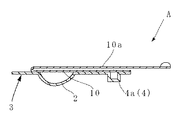
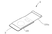
粉体用容器Aは、粉体を収納する収納皿部2を凹設した基板3と、前記収納皿部2の開口部を閉塞して基板3上に剥離可能に固着した蓋板10とを備えている。前記蓋板10の先端に蓋板10を剥離するための帯板部10a を延設している。この帯板部10a は、折り返し状態で、装着した粉体投与器Bの外方へ先端を突出する如く構成している。また、前記収納皿部2を前記収納室R内に収納した状態で粉体投与器に係合させる係合部4を設けている。   The powder container A includes a substrate 3 having a receiving tray portion 2 in which powder is stored, and a lid plate 10 that is detachably fixed on the substrate 3 by closing the opening of the storing tray portion 2. I have. A band plate portion 10a for peeling the cover plate 10 is extended at the tip of the cover plate 10. The band plate portion 10a is configured such that its tip protrudes outward from the powder dispenser B to which it is attached in a folded state. Moreover, the engaging part 4 which engages with a powder administration device in the state which accommodated the said storage tray part 2 in the said storage chamber R is provided.

図示例では、基板3は縦長矩形状をなし、中央部に半球状の収納皿部2を凹設しており、その後方位置に陥没状態で平面視四角形状の係合部4としての係合凸部4aを突設している。また、蓋板10は、前記収納皿部2の開口部を閉塞して基板3上面に剥離可能に固着させており、その先端に蓋板10と同じ幅の帯板部10a を延設している。また、基板3の上面の先端部を除いた部分に蓋板10を剥離可能に固着させている。そして、図3に示す如く、蓋板10の先端縁より後方へ帯板部10a を折り返した際に基板3後端縁より後方へ所定の長さ突設する如く構成している。ここでいう所定の長さは、前記した粉体投与器Bに装着した際に先端部が引っ張り可能に突出する程度をいう。   In the illustrated example, the substrate 3 has a vertically long rectangular shape, and a hemispherical storage tray portion 2 is recessed at the center, and is engaged as an engagement portion 4 having a rectangular shape in plan view in a depressed state at the rear position. The convex part 4a is projected. Further, the cover plate 10 closes the opening of the storage tray 2 and is fixed to the upper surface of the substrate 3 so as to be peeled off, and a band plate portion 10a having the same width as the cover plate 10 is extended to the tip thereof. Yes. Further, the cover plate 10 is detachably fixed to the portion of the upper surface of the substrate 3 except for the tip portion. Then, as shown in FIG. 3, when the band plate portion 10a is folded back from the front end edge of the lid plate 10, a predetermined length is projected rearward from the rear end edge of the substrate 3. The predetermined length here refers to the extent to which the tip portion protrudes so as to be able to be pulled when mounted on the powder administration device B described above.

粉体投与器Bは、ケース21と、前記吸口20とを備えている。   The powder administration device B includes a case 21 and the mouthpiece 20.

ケース21は、本体21a と蓋体21b とで内部に収納室Rを画成するとともに、該収納室Rと外部とを連通する通気路pを備えている。本体21a は、仕切壁22の後面下部より後方へ延設した下端開放の箱型をなしており、頂面の中央部に球面状の嵌合凹部23を凹設し、その後方に四角形状の係止凹部24を凹設している。更に一側面には係止突起25を突設している。   The case 21 includes a main body 21a and a lid 21b that define a storage chamber R therein, and a ventilation path p that communicates the storage chamber R with the outside. The main body 21a has a box shape with an open lower end that extends rearward from the lower rear surface of the partition wall 22. A spherical fitting recess 23 is formed at the center of the top surface, and a rectangular shape is formed at the rear. A locking recess 24 is provided. Furthermore, a locking projection 25 is provided on one side surface.

蓋体21b は中空箱型をなすとともに、本体21a の側面上部にヒンジ26を介して側面下部を回動可能に連結して本体21a の上面を開閉可能に設けており、ヒンジ26の反対側には、内面に係合突起27を突設した係合板を突設し、前記係合突起27を前記係止突起25と係脱可能に係合させて閉蓋状態を維持する如く構成している。また、下面の前端縁中央部から後方へ平面視半楕円形状の凹部28を凹設し、該凹部28とその下方の嵌合凹部23を含むケース本体21a 上面とで収納室Rを形成している。また、嵌合凹部23の後部上方に一端を開口して通気路pを設けている。この開口部分は蓋体21b 底面に設けた複数の透孔29として構成しており、通気路pの他端開口部分は蓋体21b の後面に設けた透孔30として構成している。従って、通気路pは透孔30から蓋体21b 内を通り透孔29を介して外部と収納室Rとを連通させている。   The lid 21b has a hollow box shape, and the lower side of the main body 21a is rotatably connected to the upper side of the main body 21a via a hinge 26 so that the upper surface of the main body 21a can be opened and closed. Is configured such that an engagement plate is provided with an engagement protrusion 27 protruding on the inner surface, and the engagement protrusion 27 is detachably engaged with the engagement protrusion 25 to maintain a closed state. . A recess 28 having a semi-elliptical shape in plan view is formed rearward from the center of the front edge of the lower surface, and a storage chamber R is formed by the recess 28 and the upper surface of the case body 21a including the fitting recess 23 below the recess 28. Yes. One end is opened above the rear part of the fitting recess 23 to provide a ventilation path p. This opening portion is configured as a plurality of through holes 29 provided on the bottom surface of the lid body 21b, and the other end opening portion of the air passage p is configured as a through hole 30 provided on the rear surface of the lid body 21b. Therefore, the ventilation path p passes through the inside of the lid 21b from the through hole 30 and communicates the outside and the storage chamber R through the through hole 29.

吸口20は前記仕切壁22の前面より前方へ突設した筒状をなし、その基端部を収納室R内と連通させている。図示例では仕切壁22に複数の透孔31を設けて連通させている。また、吸口20内中央部に軸線に沿う拡散棒32を設けている。この拡散棒32は前後方向中央部の左右にそれぞれ山型の突部32a を突設して、粉体の流れを拡散する如く構成している。   The suction port 20 has a cylindrical shape projecting forward from the front surface of the partition wall 22, and its base end communicates with the inside of the storage chamber R. In the illustrated example, a plurality of through holes 31 are provided in the partition wall 22 for communication. In addition, a diffusion rod 32 along the axis is provided at the center of the suction port 20. The diffusion rod 32 is configured to have a chevron-shaped protrusion 32a on the left and right sides of the central portion in the front-rear direction to diffuse the powder flow.

本件発明の粉体用容器Aをこの吸引式の粉体投与器Bに使用する場合について説明すると、まず、粉体投与器Bの蓋体21b をあけて粉体用容器Aを装着する。粉体用容器Aは、帯板部10a を折り返した状態でその収納皿部2を本体21a の嵌合凹部23に挿入或いは嵌合させるとともに、係合凸部4aを係止凹部24に嵌合させて設置する。次いで蓋体21b を閉じ、その係合突起27を係止突起25に係合させる。この際帯板部10a の先端部はケース21外方に突設している。次に、ケース21から突出した部分の帯板部10a を引っ張ると、固着部分が剥離して蓋板10が基板3から剥がれ、取り除くことができ、その際収納皿部2の上端開口部が開放される。尚、蓋板10はフィルム或いはシート等で形成された薄肉のものであるため、本体21a と蓋体21b との間に隙間がなくても引き出すことは可能であるが、必要であれば、蓋板10を通す小間隙を本体21a 及び/又は蓋体21b を凹ますことにより形成しても良い。次いで、吸口20を口に含んで吸い込めば、外気が通気路pを通り収納室R内に導入されるとともに、収納室R内の粉体を各透孔31を介して吸口20内を通り、吸引することができる。使用後は蓋体21b を開いて残った基板3を取り除く。   The case where the powder container A of the present invention is used in this suction-type powder administration device B will be described. First, the lid 21b of the powder administration device B is opened and the powder container A is mounted. The powder container A is inserted or fitted into the fitting recess 23 of the main body 21a with the band plate portion 10a folded, and the engaging convex portion 4a is fitted into the locking recess 24. To install. Next, the lid 21b is closed, and the engaging protrusion 27 is engaged with the locking protrusion 25. At this time, the front end portion of the belt plate portion 10a protrudes outward from the case 21. Next, when the band plate portion 10a protruding from the case 21 is pulled, the fixing portion is peeled off and the lid plate 10 is peeled off from the substrate 3 and can be removed. At this time, the upper end opening of the storage tray portion 2 is opened. Is done. Since the lid plate 10 is a thin wall formed of a film or sheet, it can be pulled out even if there is no gap between the main body 21a and the lid body 21b. A small gap passing through the plate 10 may be formed by denting the main body 21a and / or the lid 21b. Next, if the suction port 20 is sucked into the mouth, outside air is introduced into the storage chamber R through the ventilation path p, and the powder in the storage chamber R passes through the suction port 20 through the through holes 31. Can be aspirated. After use, the lid 21b is opened and the remaining substrate 3 is removed.

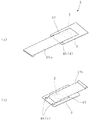
図6は他の実施形態を示すもので、本例に於ける粉体用容器Aは、その係止部4の形態が相違するものであり、基板3の前方に係止部4としての一対の係合孔4bを穿設している。その他の構成は基本的に図1の例と同様である。具体的には、後述する粉体投与器の本体21a 頂面に当接載置される大きさの矩形状の基板3を備え、基板3の中央部には半球状の収納皿部2を凹設している。蓋板10は、基板3より横幅が短い縦長矩形状をなしており、収納皿部2の開口部を閉塞して基板3上面の左右方向中央部に、先端部を残して剥離可能に固着させている。また、蓋板10の先端部に折り返し可能に帯板部10a を延設している。   FIG. 6 shows another embodiment, and the powder container A in this example is different in the form of the engaging portion 4, and a pair as the engaging portion 4 is provided in front of the substrate 3. The engagement hole 4b is formed. Other configurations are basically the same as those in the example of FIG. Specifically, a rectangular substrate 3 having a size to be placed in contact with the top surface of a main body 21a of a powder dosing device, which will be described later, is provided, and a hemispherical storage dish portion 2 is recessed at the center of the substrate 3. Has been established. The cover plate 10 has a vertically long rectangular shape whose width is shorter than that of the substrate 3, and closes the opening of the storage tray 2 so that it can be peeled and fixed at the center in the left-right direction on the upper surface of the substrate 3. ing. Further, a band plate portion 10a is extended at the front end portion of the lid plate 10 so as to be folded back.

本例の粉体用容器Aを使用する粉体投与器Bの一例として、図7及び図8に示す如き粉体投与器Bが挙げられる。この場合は粉体用容器Aを、その蓋板10が下方を向く如く収納室R内に収納係止させている。本例に於けるケース21も本体21a と蓋体21b とからなり、本体21a は、仕切壁22の裏面下部より後方へ突設した中空箱型で、頂面の中央部には平面視四角形状の粉体溜まり用の凹部33を凹設し、その前部には粉体溜まり用の凹部33と連設して粉体溜まり用の凹部33より浅い平面視台形状の連結凹部34を設けており、この連結凹部34と粉体溜まり用の凹部33及び蓋体21b 内部とで収納室Rを構成している。また、収納室Rは仕切壁22に設けた多数の透孔31を介して吸口20内と連通させている。また、粉体溜まり用の凹部33の後壁部分には通気路pの一端を透孔29として開口しており、この通気路pは各凹部の下方を通り、本体下面先端部に透孔30として他端を開口している。この場合の本体21a は頂面を形成する部分を別部材で構成している。   As an example of the powder administration device B using the powder container A of this example, there is a powder administration device B as shown in FIGS. In this case, the powder container A is stored and locked in the storage chamber R so that the cover plate 10 faces downward. The case 21 in this example also comprises a main body 21a and a lid 21b. The main body 21a is a hollow box shape projecting rearward from the lower part of the rear surface of the partition wall 22, and has a square shape in plan view at the center of the top surface. A concave portion 33 for storing the powder is provided, and a connecting concave portion 34 having a trapezoidal shape in plan view shallower than the concave portion 33 for storing the powder is provided in front of the concave portion 33 for storing the powder. The connecting recess 34, the recess 33 for storing powder, and the inside of the lid 21b constitute a storage chamber R. The storage chamber R communicates with the inside of the suction port 20 through a large number of through holes 31 provided in the partition wall 22. In addition, one end of the air passage p is opened as a through hole 29 in the rear wall portion of the concave portion 33 for storing powder, and this air passage p passes through the lower portion of each concave portion and has a through hole 30 at the tip of the lower surface of the body. The other end is opened. In this case, the main body 21a has a portion forming the top surface as a separate member.

蓋体21b はヒンジ26を介して開閉可能に本体21a に連結しており、前面及び下面を開放した箱型をなしており、頂壁の中央部には粉体用容器Aの底部が嵌合する上方へ突設する凹み35を設けており、その前部の頂壁裏面からは一対の係止筒36を垂設している。また、吸口20は図4の例と同様に仕切壁22の前面より前方へ突設している。   The lid 21b is connected to the main body 21a through a hinge 26 so as to be openable and closable. The lid 21b has a box shape with the front and bottom surfaces open, and the bottom of the powder container A is fitted in the center of the top wall. A recess 35 projecting upward is provided, and a pair of locking cylinders 36 are suspended from the back of the top wall of the front portion. Further, the suction port 20 protrudes forward from the front surface of the partition wall 22 as in the example of FIG.

本例の粉体用容器Aを使用して吸引式の粉体投与器Bを利用する場合について説明すると、まず、粉体投与器Bの蓋体21b をあけて粉体用容器Aを装着する。粉体用容器Aは、例えば、帯板部10a を折り返した状態で、各係合孔4bを蓋体21b の係止筒36の先端部に嵌合し、その底部を前記凹み35に位置させて蓋体21b に装着した後蓋体21b を閉じることにより、蓋板10を下方を向けた状態で装着する。この際、収納皿部2の下方に粉体溜まり用の凹部33が位置する。次に、ケース21から突出した帯板部10a を引っ張ると、固着部分が剥離して蓋板10が基板3から剥がれ、取り除くことができ、その際収納皿部2内の粉体が粉体溜まり用の凹部33内に落下する。次いで、吸口20を口に含んで吸い込めば、外気が通気路pを通り収納室R内に導入されるとともに、収納室R内の粉体を各透孔31及び吸口20を介して吸引することができる。   The case of using the suction type powder administration device B using the powder container A of this example will be described. First, the lid 21b of the powder administration device B is opened and the powder container A is mounted. . In the powder container A, for example, in a state in which the band plate portion 10a is folded, each engagement hole 4b is fitted to the distal end portion of the locking cylinder 36 of the lid 21b, and its bottom portion is positioned in the recess 35. Then, after the lid body 21b is mounted, the lid body 21b is closed to mount the lid plate 10 facing downward. At this time, the concave portion 33 for storing powder is located below the storage tray portion 2. Next, when the band plate portion 10a protruding from the case 21 is pulled, the adhering portion is peeled off, and the lid plate 10 is peeled off from the substrate 3 and can be removed. Falls into the recess 33 for use. Next, when the suction port 20 is sucked into the mouth, the outside air is introduced into the storage chamber R through the ventilation path p, and the powder in the storage chamber R is sucked through the through holes 31 and the suction ports 20. be able to.

図9は更に他の実施形態を示すもので、本例に於ける粉体用容器Aは、その係止部4の形態が相違するものであり、基板3の先端部両側に係止部4としての一対の係合突片4cを突設している。その他の構成は基本的に図1の例と同様である。この場合に対応する粉体投与器としては、例えば、図1の粉体投与器Bの本体21a 両側に各係合突部4aが摺動嵌合可能な一対の凹溝を設けて、その先端部分を堅嵌め状態となる如く小縦幅に形成して粉体用容器Aを係止固定する等が挙げられる。   FIG. 9 shows still another embodiment. The powder container A in this example is different in the form of the engaging part 4, and the engaging part 4 is provided on both sides of the front end part of the substrate 3. A pair of engaging protrusions 4c is provided as a protrusion. Other configurations are basically the same as those in the example of FIG. As a powder dispenser corresponding to this case, for example, a pair of concave grooves in which the respective engaging projections 4a can be slidably fitted are provided on both sides of the main body 21a of the powder dispenser B in FIG. For example, the powder container A may be locked and fixed by forming the portion with a small vertical width so as to be in a tightly fitted state.

図10は更に他の実施形態を示すもので、基板3を積層構造で形成した例を示す。図示例では、基板3を表面層3a及び下面層3bの二層で構成しており、表面層3aは縦方向の長さを下面層3bより短く形成して下面層3bの先端部が露出する如く積層されている。また、蓋板10を表面層3a上に固着する如く構成している。更に係合部4として係合凸部4aを採用している。この場合には表面層3aに表面円滑性の樹脂を採用したり、或いは蓋板10との剥離性の良い材質を選ぶ等の樹脂の選択を行える。尚、この積層構造は他の係合部4の形態にも採用できる。   FIG. 10 shows still another embodiment and shows an example in which the substrate 3 is formed in a laminated structure. In the illustrated example, the substrate 3 is composed of two layers, a surface layer 3a and a lower surface layer 3b. The surface layer 3a is formed to have a shorter length in the vertical direction than the lower surface layer 3b, and the tip of the lower surface layer 3b is exposed. Are stacked as shown. Further, the cover plate 10 is configured to be fixed on the surface layer 3a. Furthermore, the engaging convex part 4a is employ | adopted as the engaging part 4. FIG. In this case, it is possible to select a resin such as adopting a resin having a smooth surface for the surface layer 3a, or selecting a material having good peelability from the lid plate 10. Note that this laminated structure can also be adopted in the form of the other engaging portions 4.

図11及び図12は更に他の実施形態を示すもので、粉体投与器に装着する際に挟持させて蓋板10を剥離させるための挟持部eを、蓋板10の先端部に延設した例である。この場合の粉体用容器Aは、基板3に凹設した収納皿部2の開口部を閉塞して剥離可能に蓋板10を固着し、また、先端部には後述する粉体投与器の蓋体と係止板との間に起立状態で挟持させる挟持部eを設けている。図示例に於いて挟持部eは、蓋板10の先端部より延設した蓋板延長部10b と、該蓋板延長部10b 裏面に固着した保護板部7とで構成している。また、保護板部は基板40と薄肉の破断部8で連結している。破断部8の形態は薄肉に限らず細棒状の連結形態であっても、ミシン目形態であっても良く、また、破断部を設けずに独立した保護板部を設けても良い。基板3は縦長矩形状をなし、中央部に半球状の収納皿部2を凹設している。また、蓋板10は収納皿部2の開口部を閉塞して基板3上面に剥離可能に固着させており、蓋板10先端より延設した蓋板延長部10b の下面には略同形状の保護板部7を固着している。尚、挟持部eは、前記した保護板部を設けたものに限らず、単に蓋板延長部10b のみで構成しても良く、或いは、蓋板延長部部分を肉厚に形成したものであっても良い。

FIG. 11 and FIG. 12 show still another embodiment. A clamping portion e for clamping and peeling the lid plate 10 when attached to the powder administration device is extended to the distal end portion of the lid plate 10. This is an example. In this case, the container A for powders closes the opening of the storage dish part 2 provided in the base plate 3 so that the cover plate 10 can be peeled off. A clamping part e is provided between the lid and the locking plate so as to be clamped in an upright state. In the illustrated example, the sandwiching portion e is composed of a lid plate extension portion 10b extending from the front end portion of the lid plate 10 and a protective plate portion 7 fixed to the back surface of the lid plate extension portion 10b. Further, the protective plate portion 7 is connected to the substrate 40 by a thin broken portion 8. The form of the breaking part 8 is not limited to a thin wall, but may be a thin rod-like connection form or a perforation form, or an independent protective plate part may be provided without providing a breaking part. The substrate 3 has a vertically long rectangular shape, and a hemispherical storage tray 2 is recessed in the center. Further, the cover plate 10 closes the opening of the storage tray 2 and is fixed to the upper surface of the substrate 3 so as to be peeled off. The lower surface of the cover plate extension 10b extending from the tip of the cover plate 10 has substantially the same shape. The protective plate portion 7 is fixed. Note that the clamping portion e is not limited to the one provided with the protective plate portion described above, and may be configured only by the cover plate extension portion 10b, or the cover plate extension portion portion is formed thick. May be.

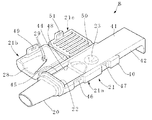
本例の粉体用容器Aを使用する粉体投与器Bの一例として、図13乃至図16に示す如き粉体投与器Bが挙げられる。   An example of a powder administration device B that uses the powder container A of this example is a powder administration device B as shown in FIGS.

ケース21は、本体21a 及び該本体21a 上面を開閉可能に設けた蓋体21b とで内部に収納室Rを画成するとともに、該収納室と外部とを連通する通気路pを備えている。また、本体21a は蓋体21b の後方へ延設するとともに、その頂板をスライド可能に形成し、更に、本体21a 上面を開閉可能な係止板を蓋体21b と併設している。図示例に於いて本体21a は、仕切壁22の後面下部より後方へ突設するとともに、底壁の両側よりそれぞれ側壁を立設した形態の半管状の支持壁部40と、該支持壁部上端開口部を閉塞してスライド可能に嵌合させた頂板41とで構成している。頂板41はその周縁部から下方へ垂壁部42を垂設し、後縁の垂壁部は指掛け部43として下方へより長く垂設している。また、垂壁部42の両側先端部に摺動突起44を突設し、該摺動突起44を前記支持壁部40内面両側に凹設した案内溝45に摺動可能に嵌合させている。また、頂板41の前部には球面状の嵌合凹部23を凹設している。更に、一側面に所定間隔離れて形成した一対の凹部内にそれぞれ蓋体用の第1係止突起46及び係止板用の第2係止突起47を突設している。   The case 21 includes a main body 21a and a lid body 21b that is provided so that the upper surface of the main body 21a is openable and closable, and includes a ventilation path p that communicates the storage chamber with the outside. The main body 21a extends rearward from the lid 21b, and its top plate is slidably formed. Further, a locking plate capable of opening and closing the upper surface of the main body 21a is provided together with the lid 21b. In the illustrated example, the main body 21a has a semi-tubular support wall portion 40 that protrudes rearward from the lower rear surface of the partition wall 22 and has side walls erected from both sides of the bottom wall, and an upper end of the support wall portion. The top plate 41 is slidably fitted with the opening closed. The top plate 41 has a hanging wall part 42 suspended downward from the peripheral edge thereof, and the trailing wall part of the rear edge is suspended downward longer as a finger hanging part 43. Sliding projections 44 project from the front end portions on both sides of the vertical wall portion 42, and the sliding projections 44 are slidably fitted into guide grooves 45 that are recessed on both sides of the inner surface of the support wall portion 40. . Further, a spherical fitting recess 23 is provided in the front portion of the top plate 41. Further, a first locking projection 46 for the lid and a second locking projection 47 for the locking plate are respectively provided in a pair of recesses formed on the one side surface at a predetermined interval.

蓋体21b は中空箱型をなし、本体21a の側面上部に第1ヒンジ48を介して側面下部を回動可能に連結して本体21a の上面を開閉可能に設けており、第1ヒンジ48の反対側には、内面に第1係合突起49を突設した係合板を垂設し、該第1係合突起49を前記第1係止突起46と係脱可能に係合させて閉蓋状態を維持する如く構成している。また、下面の前端縁中央部から後方へ平面視半楕円形状の凹部28を凹設し、該凹部28とその下方の前記嵌合凹部23を含む本体21a 上面とで収納室Rを形成している。また、嵌合凹部23の後部上方に一端を開口して通気路pを設けている。この開口部分は蓋体21b の前記凹部28の後壁面に設けた複数の透孔29として構成しており、通気路pの他端開口部分は蓋体21b の後面に設けた透孔30として構成している。従って通気路pは透孔30から蓋体21b 内を通り透孔29を介して、外部と収納室Rとを連通させている。尚、蓋体21b は下面を形成する部分を別部材で構成している。   The lid body 21b has a hollow box shape, and the lower surface of the main body 21a is rotatably connected to the upper surface of the main body 21a via the first hinge 48 so that the upper surface of the main body 21a can be opened and closed. On the opposite side, an engagement plate having a first engagement protrusion 49 projecting from the inner surface is suspended, and the first engagement protrusion 49 is detachably engaged with the first engagement protrusion 46 to close the lid. It is configured to maintain the state. Further, a concave part 28 having a semi-elliptical shape in plan view is provided rearward from the central part of the front edge of the lower surface, and a storage chamber R is formed by the concave part 28 and the upper surface of the main body 21a including the fitting concave part 23 below the concave part 28. Yes. One end is opened above the rear part of the fitting recess 23 to provide a ventilation path p. This opening portion is configured as a plurality of through holes 29 provided in the rear wall surface of the recess 28 of the lid 21b, and the other end opening portion of the air passage p is configured as a through hole 30 provided in the rear surface of the lid body 21b. is doing. Therefore, the air passage p allows the outside and the storage chamber R to communicate with each other through the through hole 30 through the inside of the lid 21b. Note that the lid 21b is formed of a separate member at the portion forming the lower surface.

係止板21c は蓋体21b の後方の本体21a の側面上部に第2ヒンジ50を介して側面下部を回動可能に連結して本体21a の上面を開閉可能に設けており、第2ヒンジ50の反対側には、内面に第2係合突起51を突設した係合板を垂設し、該第2係合突起51を前記第2係止突起47と係脱可能に係合させて係止状態を維持する如く構成している。係止板21c と蓋体21b との間は粉体用容器Aの端部を挟持できる程度の隙間を設けている。   The locking plate 21c is pivotally connected to the upper part of the side surface of the main body 21a behind the lid 21b via the second hinge 50 so that the upper surface of the main body 21a can be opened and closed. On the opposite side, an engagement plate having a second engagement projection 51 projecting from the inner surface is suspended, and the second engagement projection 51 is detachably engaged with the second engagement projection 47 to engage. The stop state is maintained. A gap is provided between the locking plate 21c and the lid 21b so as to sandwich the end of the powder container A.

吸口20は前記仕切壁22の前面より前方へ突設した筒状をなし、その基端部を収納室R内と連通させている。図示例では仕切壁22に複数の透孔31を設けて収納室R内と連通させている。   The suction port 20 has a cylindrical shape projecting forward from the front surface of the partition wall 22, and its base end communicates with the inside of the storage chamber R. In the illustrated example, a plurality of through holes 31 are provided in the partition wall 22 to communicate with the interior of the storage chamber R.

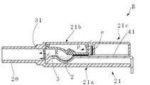
上記の如く構成した吸引式の粉体投与器Bを使用する場合について説明すると、まず、図14に示す如く、粉体投与器Bの蓋体21b を閉じ、係止板21c を開いた状態で頂板41を後方所定位置まで引き出し、嵌合凹部23に収納皿部2を挿入或いは嵌合させるとともに、挟持部eを起立させて蓋体21b 後面に当接させて粉体用容器Aを装着する。次いで図15に示す如く、係止板21c を閉じてその第2係合突起51を第2係止突起47に係合させるとともに、蓋体21b 後面と係止板21c 前面とで挟持部eを挟持固定する。次に、図16に示す如く、頂板41を押し込んで蓋板10と頂板41前部とで収納室Rを画成する。この際粉体用容器Aの蓋板10は挟持部eが固定されているため頂板41の押し込みに伴って破断部8が切断されるとともに、順次基板3から剥がれて最終的に収納皿部2の開口部を開放する。蓋板10の後端部は剥がれずにそのまま基板3上に固着状態にあり、また、剥がれた部分は固着部分の上に折り返した状態で残存する。次いで、吸口20を口に含んで吸い込めば、外気が通気路pを通り収納室R内に導入されるとともに、収納室R内の粉体を各透孔31及び吸口20内を介して吸引することができる。   The case where the suction type powder administration device B configured as described above is used will be described. First, as shown in FIG. 14, the lid 21b of the powder administration device B is closed and the locking plate 21c is opened. The top plate 41 is pulled back to a predetermined position, and the storage tray portion 2 is inserted or fitted into the fitting recess 23, and the holding portion e is erected and brought into contact with the rear surface of the lid 21b to mount the powder container A. . Next, as shown in FIG. 15, the locking plate 21c is closed and the second engaging projection 51 is engaged with the second locking projection 47, and the clamping portion e is formed between the rear surface of the lid 21b and the front surface of the locking plate 21c. Clamp and fix. Next, as shown in FIG. 16, the top plate 41 is pushed in, and the storage chamber R is defined by the lid plate 10 and the front portion of the top plate 41. At this time, since the cover plate 10 of the powder container A has the clamping portion e fixed, the breaking portion 8 is cut as the top plate 41 is pushed, and is sequentially peeled off from the substrate 3 and finally the storage plate portion 2. Open the opening. The rear end portion of the lid plate 10 is not peeled off and is fixed to the substrate 3 as it is, and the peeled portion remains on the fixed portion in a folded state. Next, if the suction port 20 is sucked into the mouth, outside air is introduced into the storage chamber R through the ventilation path p, and the powder in the storage chamber R is sucked through the through holes 31 and the suction port 20. can do.

本発明粉体用容器の縦断面図である。(実施例1)It is a longitudinal cross-sectional view of this invention powder container. Example 1 本発明粉体用容器の斜視図である。(実施例1)It is a perspective view of the container for powders of the present invention. Example 1 本発明粉体用容器の斜視図である。(実施例1)It is a perspective view of the container for powders of the present invention. Example 1 本発明粉体用容器を粉体投与器に装着する際の斜視図である。(実施例1)It is a perspective view at the time of mounting | wearing the powder container with this invention powder container. Example 1 本発明粉体用容器を粉体投与器に装着した際の縦断面図である。(実施例1)It is a longitudinal cross-sectional view at the time of mounting | wearing the powder administration device with the powder container of the present invention. Example 1 本発明粉体用容器の斜視図である。(実施例2)It is a perspective view of the container for powders of the present invention. (Example 2) 本発明粉体用容器を粉体投与器に装着する際の平面図である。(実施例2)It is a top view at the time of mounting | wearing the powder container with this invention powder container. (Example 2) 本発明粉体用容器を粉体投与器に装着した際の縦断面図である。(実施例2)It is a longitudinal cross-sectional view at the time of mounting | wearing the powder administration device with the powder container of the present invention. (Example 2) 本発明粉体用容器の斜視図である。(実施例3)It is a perspective view of the container for powders of the present invention. Example 3 本発明粉体用容器の斜視図である。(実施例4)It is a perspective view of the container for powders of the present invention. (Example 4) 本発明粉体用容器の斜視図である。(実施例5)It is a perspective view of the container for powders of the present invention. (Example 5) 本発明粉体用容器の縦断面図である。(実施例5)It is a longitudinal cross-sectional view of this invention powder container. (Example 5) 本発明粉体用容器を使用する粉体投与器の斜視図である。(実施例5)It is a perspective view of the powder administration device which uses the container for powders of the present invention. (Example 5) 本発明粉体用容器を粉体投与器に装着する際の斜視図である。(実施例5)It is a perspective view at the time of mounting | wearing the powder container with this invention powder container. (Example 5) 本発明粉体用容器を粉体投与器に装着する際の斜視図である。(実施例5)It is a perspective view at the time of mounting | wearing the powder container with this invention powder container. (Example 5) 本発明粉体用容器を粉体投与器に装着した際の斜視図である。(実施例5)It is a perspective view at the time of mounting | wearing the powder container with the container for powder of this invention. (Example 5)

符号の説明Explanation of symbols

2…収納皿部,3…基板,4…係合部,4a…係合凸部,4b…係合孔,10…蓋板,
10a …帯板部,24…係止凹部,36…係止筒,A…粉体用容器,
B…吸引式の粉体投与器,R…収納室,p…挟持部
2 ... storage tray part, 3 ... substrate, 4 ... engagement part, 4a ... engagement convex part, 4b ... engagement hole, 10 ... lid plate,
10a ... strip plate part, 24 ... locking recess, 36 ... locking cylinder, A ... powder container,
B ... Suction type powder administration device, R ... Storage room, p ... Nipping part

Claims (3)

頂板(41)をスライド可能に形成した本体(21a) と、該本体(21a) 上面を開閉可能に設けた蓋体(21b) とで内部に収納室(R) を画成し、本体(21a) 上面を開閉可能な係止板(21c) を蓋体(21b) と併設し、収納室(R) 内の粉体を吸口(20)から吸引する如く構成した吸引式の粉体投与器(B) に使用する粉体用容器(A) であって、粉体を収納する収納皿部(2) を凹設した基板(3) と、収納皿部(2) の開口部を閉塞して基板(3) 上に剥離可能に固着した蓋板(10)と、蓋板(10)の先端部に延設した挟持部(e) とを備え、引き出した頂板(41)に凹設された嵌合凹部(23)に収納皿部(2) を挿入或いは嵌合させるとともに、蓋板(10)より起立させた挟持部(e) を蓋体(21b) と係止板(21c) との間に挟持した状態から、本体(21a) に対して頂板(41)を押し込むことで、蓋板(10)が剥離しつつ収納凹部(2) が収納室(R) 内に移行することを特徴とする粉体用容器。 And a body formed top plate (41) slidably (21a), defining the body (21a) upper surface openably provided a lid (21b) and de storage chamber inside the (R), the body (21a ) A suction-type powder administration device ( 21c) that can be opened and closed with the lid (21b) and configured to suck the powder in the storage chamber (R ) from the suction port (20) ( a powder container for use in B) (a), storage pan for accommodating the powder and (2) substrate (3) having recessed and closes the opening of the housing pan (2) The lid plate (10) is detachably fixed on the substrate (3) , and the clamping portion (e) is extended to the tip of the lid plate (10) , and is recessed in the drawn top plate (41). The storage tray (2) is inserted or fitted into the fitting recess (23), and the clamping portion (e) raised from the lid plate (10 ) is placed between the lid (21b) and the locking plate (21c) . When the top plate (41) is pushed into the main body (21a) from the state of being sandwiched therebetween, the cover recess (2) moves into the storage chamber (R) while the cover plate (10) is peeled off. And a container for powder. 前記基板(3) を積層構造で構成してなる請求項1に記載の粉体用容器。 2. The powder container according to claim 1, wherein the substrate (3) is constituted by a laminated structure. 前記挟持部(e) が、蓋板(10)先端部より延設した蓋板延長部(10b) と、該蓋板延長部(10b) 裏面に固着した保護板部(7) とで構成してなる請求項1又は請求項2のいずれか一項に記載の粉体用容器。 The clamping portion (e) is, cover plate (10) cover plate extension which is extended from the tip portion and (10b), constitute de lid plate extensions (10b) protective plate fixed to the back surface (7) The powder container according to any one of claims 1 and 2.
JP2005104758A 2005-03-31 2005-03-31 Powder container Expired - Fee Related JP4656397B2 (en)

Priority Applications (1)

Application Number Priority Date Filing Date Title
JP2005104758A JP4656397B2 (en) 2005-03-31 2005-03-31 Powder container

Applications Claiming Priority (1)

Application Number Priority Date Filing Date Title
JP2005104758A JP4656397B2 (en) 2005-03-31 2005-03-31 Powder container

Publications (2)

Publication Number Publication Date
JP2006280620A JP2006280620A (en) 2006-10-19
JP4656397B2 true JP4656397B2 (en) 2011-03-23

Family

ID=37403135

Family Applications (1)

Application Number Title Priority Date Filing Date
JP2005104758A Expired - Fee Related JP4656397B2 (en) 2005-03-31 2005-03-31 Powder container

Country Status (1)

Country Link
JP (1) JP4656397B2 (en)

Families Citing this family (27)

* Cited by examiner, † Cited by third party
Publication number Priority date Publication date Assignee Title
US9006175B2 (en) 1999-06-29 2015-04-14 Mannkind Corporation Potentiation of glucose elimination
WO2003080149A2 (en) 2002-03-20 2003-10-02 Mannkind Corporation Inhalation apparatus
JP5078014B2 (en) 2004-08-20 2012-11-21 マンカインド コーポレイション Catalytic reaction of diketopiperazine synthesis.
HUE026797T2 (en) 2004-08-23 2016-07-28 Mannkind Corp Diketopiperazine salts for drug delivery
KR20120060245A (en) 2005-09-14 2012-06-11 맨카인드 코포레이션 Method of drug formulation based on increasing the affinity of crystalline microparticle surfaces for active agents
EP2497484A3 (en) 2006-02-22 2012-11-07 MannKind Corporation A method for improving the pharmaceutic properties of microparticles comprising diketopiperazine and an active agent
US8485180B2 (en) 2008-06-13 2013-07-16 Mannkind Corporation Dry powder drug delivery system
EP3281663B8 (en) 2008-06-13 2022-09-21 MannKind Corporation Breath powered dry powder inhaler for drug delivery
US9364619B2 (en) 2008-06-20 2016-06-14 Mannkind Corporation Interactive apparatus and method for real-time profiling of inhalation efforts
TWI494123B (en) 2008-08-11 2015-08-01 Mannkind Corp Use of ultrarapid acting insulin
US8314106B2 (en) 2008-12-29 2012-11-20 Mannkind Corporation Substituted diketopiperazine analogs for use as drug delivery agents
CA2754595C (en) 2009-03-11 2017-06-27 Mannkind Corporation Apparatus, system and method for measuring resistance of an inhaler
WO2010144789A2 (en) 2009-06-12 2010-12-16 Mannkind Corporation Diketopiperazine microparticles with defined specific surface areas
CA2778698A1 (en) 2009-11-03 2011-05-12 Mannkind Corporation An apparatus and method for simulating inhalation efforts
AU2011271097B2 (en) 2010-06-21 2014-11-27 Mannkind Corporation Dry powder drug delivery system and methods
CN105667994B (en) 2011-04-01 2018-04-06 曼金德公司 Blister package for pharmaceutical kit
WO2012174472A1 (en) 2011-06-17 2012-12-20 Mannkind Corporation High capacity diketopiperazine microparticles
KR20140095483A (en) 2011-10-24 2014-08-01 맨카인드 코포레이션 Methods and compositions for treating pain
JP6218747B2 (en) * 2011-12-16 2017-10-25 インドシス リミテッド Drug unit dose cartridge and delivery device
DK2872205T3 (en) 2012-07-12 2017-02-27 Mannkind Corp DRY POWDER FORMAL ADMINISTRATION SYSTEM
WO2014066856A1 (en) 2012-10-26 2014-05-01 Mannkind Corporation Inhalable influenza vaccine compositions and methods
KR102499439B1 (en) 2013-03-15 2023-02-13 맨카인드 코포레이션 Microcrystalline diketopiperazine compositions and methods
WO2015010092A1 (en) 2013-07-18 2015-01-22 Mannkind Corporation Heat-stable dry powder pharmaceutical compositions and methods
JP2016530930A (en) 2013-08-05 2016-10-06 マンカインド コーポレイション Ventilation device and method
WO2015148905A1 (en) 2014-03-28 2015-10-01 Mannkind Corporation Use of ultrarapid acting insulin
US10561806B2 (en) 2014-10-02 2020-02-18 Mannkind Corporation Mouthpiece cover for an inhaler
ES2955977T3 (en) * 2017-09-19 2023-12-11 Iconovo Ab Dry powder inhaler comprising a housing with a first housing part and a second housing part

Citations (4)

* Cited by examiner, † Cited by third party
Publication number Priority date Publication date Assignee Title
JPH08503910A (en) * 1992-09-30 1996-04-30 アール.ピー.シェーラー コーポレーション Blister pack with stepped end and use of the step
JPH11510412A (en) * 1995-08-10 1999-09-14 アストラ・アクチエボラーグ Inhaler
JP2001046469A (en) * 1999-08-11 2001-02-20 Takeda Chem Ind Ltd Blister pack
WO2003082389A1 (en) * 2002-03-29 2003-10-09 Dimitrios Pentafragas Dry powder inhaler

Patent Citations (5)

* Cited by examiner, † Cited by third party
Publication number Priority date Publication date Assignee Title
JPH08503910A (en) * 1992-09-30 1996-04-30 アール.ピー.シェーラー コーポレーション Blister pack with stepped end and use of the step
JPH11510412A (en) * 1995-08-10 1999-09-14 アストラ・アクチエボラーグ Inhaler
JP2001046469A (en) * 1999-08-11 2001-02-20 Takeda Chem Ind Ltd Blister pack
WO2003082389A1 (en) * 2002-03-29 2003-10-09 Dimitrios Pentafragas Dry powder inhaler
JP2005521483A (en) * 2002-03-29 2005-07-21 ペンタフラガス、ディミトリオス Dry powder inhaler

Also Published As

Publication number Publication date
JP2006280620A (en) 2006-10-19

Similar Documents

Publication Publication Date Title
JP4656397B2 (en) Powder container
US9604759B2 (en) Pouch container
US4384649A (en) Dispensing package
SI9620082A (en) Inhaler for administering medicaments from blister packs
JP4875157B2 (en) Acupuncture packaging containers
JP6765385B2 (en) Hearing aid battery package
BRPI0609319A2 (en) ophthalmic lens packaging with internal drainage element
US20070062843A1 (en) Face mask packaging, dispensing system, and method
US20130015197A1 (en) Button Cell Battery Dispenser Package
JP2008535002A (en) Ophthalmic lens package
JP2008535023A (en) Snap-lift contact lens container
JP2012516725A (en) Device for storing and providing drug wafer and method of use
JP4475530B2 (en) Suction powder dispenser
JP4582582B2 (en) Powder aspirator
KR20170017715A (en) Packaging bag for sandwich
JP4711286B2 (en) Suction powder dispenser
US6640995B2 (en) Contact lens dispensing system
KR20070110131A (en) Contact lens package
JP3828698B2 (en) Blister pack
WO2008063037A1 (en) The opening of beverage vessel with stopper
JP4317612B2 (en) Interdental brush housing case
JP5014735B2 (en) Suction dispenser
US6571956B2 (en) Ear piercing cartridge and clutch holder kit
WO2006057600A1 (en) Container unit for containing and dispensing tablets arranged in blister packs
JP2006282245A (en) Wet material storing container, and wet tissue packaging body

Legal Events

Date Code Title Description
A621 Written request for application examination

Free format text: JAPANESE INTERMEDIATE CODE: A621

Effective date: 20070927

A131 Notification of reasons for refusal

Free format text: JAPANESE INTERMEDIATE CODE: A131

Effective date: 20091224

A977 Report on retrieval

Free format text: JAPANESE INTERMEDIATE CODE: A971007

Effective date: 20091224

A521 Written amendment

Free format text: JAPANESE INTERMEDIATE CODE: A523

Effective date: 20100218

A131 Notification of reasons for refusal

Free format text: JAPANESE INTERMEDIATE CODE: A131

Effective date: 20100317

A521 Written amendment

Free format text: JAPANESE INTERMEDIATE CODE: A523

Effective date: 20100517

TRDD Decision of grant or rejection written
A01 Written decision to grant a patent or to grant a registration (utility model)

Free format text: JAPANESE INTERMEDIATE CODE: A01

Effective date: 20101215

A01 Written decision to grant a patent or to grant a registration (utility model)

Free format text: JAPANESE INTERMEDIATE CODE: A01

A61 First payment of annual fees (during grant procedure)

Free format text: JAPANESE INTERMEDIATE CODE: A61

Effective date: 20101215

FPAY Renewal fee payment (event date is renewal date of database)

Free format text: PAYMENT UNTIL: 20140107

Year of fee payment: 3

R150 Certificate of patent or registration of utility model

Free format text: JAPANESE INTERMEDIATE CODE: R150

Ref document number: 4656397

Country of ref document: JP

Free format text: JAPANESE INTERMEDIATE CODE: R150

LAPS Cancellation because of no payment of annual fees