JP4655902B2 - Cooling module - Google Patents
Cooling module Download PDFInfo
- Publication number
- JP4655902B2 JP4655902B2 JP2005338043A JP2005338043A JP4655902B2 JP 4655902 B2 JP4655902 B2 JP 4655902B2 JP 2005338043 A JP2005338043 A JP 2005338043A JP 2005338043 A JP2005338043 A JP 2005338043A JP 4655902 B2 JP4655902 B2 JP 4655902B2
- Authority
- JP
- Japan
- Prior art keywords
- shroud
- air flow
- heat exchanger
- curved surface
- blower
- Prior art date
- Legal status (The legal status is an assumption and is not a legal conclusion. Google has not performed a legal analysis and makes no representation as to the accuracy of the status listed.)
- Expired - Fee Related
Links
Images

Description
本発明は、熱交換器とシュラウドとを一体に組み付けたクーリングモジュールに関する。 The present invention relates to a cooling module in which a heat exchanger and a shroud are assembled together.
従来より、冷媒を冷却するコンデンサ、エンジン冷却水を冷却するラジエータ、コンデンサおよびラジエータに冷却空気を流通させる送風機、コンデンサおよびラジエータを通過する空気流をガイドするシュラウド等から構成されるクーリングモジュールが知られている。(例えば、特許文献1参照)。 Conventionally, there has been known a cooling module including a condenser for cooling the refrigerant, a radiator for cooling the engine cooling water, a blower for circulating cooling air to the condenser and the radiator, a shroud for guiding the air flow passing through the condenser and the radiator, and the like. ing. (For example, refer to Patent Document 1).
このようなクーリングモジュールにおいて、図4に示すように、シュラウドJ4をコンデンサJ1側まで延長し、ラジエータJ2とコンデンサJ1とをシュラウドJ4で繋ぐレイアウトがある。このとき、振動や熱膨張による干渉を防止するために、シュラウドJ4はコンデンサJ1およびラジエータJ2と隙間を設けて組み付けられている。
しかしながら、上記レイアウトのクーリングモジュールにおいて、送風機J3が作動してシュラウドJ4の空気流れ上流側の端部J41とコンデンサJ1のモジュレータJ13との隙間J14から冷却風が流入する際に、シュラウドJ4の空気流れ上流側の端部J41のエッジ部において冷却風の流れが乱され、騒音が発生するという問題がある。 However, in the cooling module having the above layout, when the blower J3 is activated and cooling air flows from the gap J14 between the upstream end J41 of the shroud J4 and the modulator J13 of the condenser J1, the air flow of the shroud J4. There is a problem that the flow of the cooling air is disturbed at the edge portion of the upstream end portion J41 and noise is generated.
本発明は、上記点に鑑み、送風機作動時の騒音を低減することができるクーリングモジュールを提供することを目的とする。 An object of this invention is to provide the cooling module which can reduce the noise at the time of fan operation | movement in view of the said point.
上記目的を達成するため、請求項1に記載の発明では、通過する空気と熱媒体との熱交換を行うコア部(11)を有する熱交換器(1)と、熱交換器(1)の空気流れ下流側に配置され、熱交換器(1)に空気を供給する送風機(3)と、送風機(3)を保持するとともに、熱交換器(1)から送風機(3)に至る空気通路を形成するシュラウド(4)とを備え、
送風機(3)は熱交換器(1)よりも車両後方側に配置され、
シュラウド(4)の空気流れ上流側の端部(41、42)は、熱交換器(1)のうちコア部(11)の側方に配置される側方部(12a、13)の最前面よりも車両後方側に位置しており、
シュラウド(4)の空気流れ上流側の端部(41、42)と側方部(12a、13)との間には、隙間(14、15)が設けられており、
シュラウド(4)は、空気流れ下流側から空気流れ上流側へ向かって車両幅方向寸法が次第に拡大する形状であり、
シュラウド(4)の空気流れ上流側部分は、側方部(12a、13)の表面に沿って車両前方側に延びており、
シュラウド(4)の空気流れ上流側の端部(41、42)には、車両幅方向に広がる曲面が形成されており、
隙間(14、15)は、空気流れ上流側に向かって車両幅方向に広がっていることを特徴としている。
In order to achieve the above object, according to the first aspect of the present invention , a heat exchanger (1) having a core portion (11) for performing heat exchange between air passing through and a heat medium, and a heat exchanger (1). disposed in the air flow downstream side, the heat exchanger (1) for supplying air to the blower (3) and holds the blower (3), an air passage extending heat exchanger (1) to the blower (3) A shroud (4) forming
The blower (3) is disposed on the vehicle rear side of the heat exchanger (1),
The air flow upstream end portions (41, 42) of the shroud (4) are the forefront surfaces of the side portions (12a, 13) arranged on the side of the core portion (11) in the heat exchanger (1). Is located behind the vehicle,
A gap (14 , 15 ) is provided between the end (41 , 42 ) of the air flow upstream side of the shroud (4) and the side part (12a, 13) ,
The shroud (4) has a shape in which the dimension in the vehicle width direction gradually increases from the air flow downstream side toward the air flow upstream side,
The air flow upstream portion of the shroud (4) extends to the vehicle front side along the surface of the side portions (12a, 13),
A curved surface extending in the vehicle width direction is formed at the end (41 , 42 ) of the air flow upstream side of the shroud (4),
Gap (14, 15) is that towards the air flow upstream side extends in the vehicle width direction as a feature.
これにより、隙間(14、15)から流入する空気は、シュラウド(4)の空気流れ上流側の端部(41、42)に形成された車両幅方向に広がる曲面に沿ってスムーズにガイドされるため、送風機(3)作動時の騒音を低減することが可能となる。 Thereby, the air flowing in from the gaps (14 , 15 ) is smoothly guided along the curved surface extending in the vehicle width direction formed at the end (41 , 42 ) on the upstream side of the air flow of the shroud (4). Therefore, it becomes possible to reduce noise during operation of the blower (3).
具体的には、請求項2に記載の発明のように、請求項1に記載のクーリングモジュールにおいて、曲面を、シュラウド(4)の空気流れ上流側の端部(41、42)の板面が、空気流れ上流側に向かって車両幅方向に広がる湾曲面をなすことにより構成してもよい。 Specifically, as in the invention according to claim 2, in the cooling module according to claim 1, the curved surface has a plate surface of the end portion (41 , 42 ) on the upstream side of the air flow of the shroud (4). In addition, a curved surface that extends in the vehicle width direction toward the upstream side of the air flow may be formed.
また、請求項3に記載の発明では、請求項1または2に記載のクーリングモジュールにおいて、側方部(12a、13)における前記シュラウド(4)の前記曲面に対向する部位には、前記シュラウド(4)側に突出する曲面が形成されていることを特徴としている。 Moreover, in invention of Claim 3, in the cooling module of Claim 1 or 2, the site | part which opposes the said curved surface of the said shroud (4) in a side part (12a, 13) WHEREIN: The said shroud ( that 4) curved surface convex toward the side is formed is set to feature.
これにより、隙間(14、15)から流入する空気は、シュラウド(4)の空気流れ上流側の端部(41、42)に形成された曲面に沿ってスムーズにガイドされるとともに、熱交換器(1)の側方部(12a、13)に形成された曲面に沿ってスムーズにガイドされるため、送風機(3)作動時の騒音をより低減することが可能となる。 Thereby, the air flowing in from the gaps (14 , 15 ) is smoothly guided along the curved surface formed at the end (41 , 42 ) on the upstream side of the air flow of the shroud (4), and the heat exchanger. Since it is smoothly guided along the curved surface formed on the side portions (12a, 13) of (1) , it becomes possible to further reduce noise during operation of the blower (3).
また、具体的には、請求項4に記載の発明のように、請求項1ないし3のいずれか1つに記載のクーリングモジュールにおいて、側方部は、熱交換器(1)の付属部品(13)により構成してもよい。
そして、請求項5に記載の発明のように、請求項4に記載のクーリングモジュールにおいて、熱交換器を、冷凍サイクル内を循環する冷媒と空気とを熱交換して冷媒を凝縮させるコンデンサ(1)とし、付属部品(13)は、コンデンサ(1)により凝縮された冷媒を気液分離するモジュレータ(13)であり、このモジュレータ(13)の表面形状によりシュラウド(4)側に突出する曲面を構成してもよい。
Specifically, as in the invention according to claim 4, in the cooling module according to any one of claims 1 to 3, the side portion is an accessory part of the heat exchanger (1) ( 13).
And like invention of Claim 5, in the cooling module of Claim 4, the condenser (1 which heat-exchanges the refrigerant | coolant and air which circulate in the refrigerating cycle, and condenses a refrigerant | coolant in a heat exchanger. ), And the accessory part (13) is a modulator (13) that separates the refrigerant condensed by the condenser (1) into a gas-liquid separator , and a curved surface that protrudes toward the shroud (4) by the surface shape of the modulator (13). It may be configured.
なお、上記各手段の括弧内の符号は、後述する実施形態に記載の具体的手段との対応関係を示すものである。 In addition, the code | symbol in the bracket | parenthesis of each said means shows the correspondence with the specific means as described in embodiment mentioned later.
(第1実施形態)
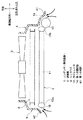
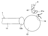
以下、本発明の第1実施形態について図1および図2に基づいて説明する。本第1実施形態のクーリングモジュールは車両用であり、このクーリングモジュールは、通常、車両の前端部に搭載される。図1は本第1実施形態に係るクーリングモジュールを示す斜視図で、図2は図1のA−A断面図である。なお、図1において、ラジエータ2、送風機3およびシュラウド4は図示を省略している。
(First embodiment)
Hereinafter, a first embodiment of the present invention will be described with reference to FIGS. 1 and 2. The cooling module of the first embodiment is for a vehicle, and this cooling module is usually mounted at the front end of the vehicle. FIG. 1 is a perspective view showing a cooling module according to the first embodiment, and FIG. 2 is a cross-sectional view taken along line AA of FIG. In FIG. 1, the radiator 2, the blower 3, and the shroud 4 are not shown.
図1および図2に示すように、本実施形態のクーリングモジュールは、図示しない冷凍サイクル内を循環する冷媒と外気とを熱交換して冷媒を冷却するコンデンサ1と、図示しないエンジン(内燃機関)の冷却水と外気とを熱交換させて冷却水を冷却するラジエータ2と、コンデンサ1およびラジエータ2に冷却風を送風する送風機3と、送風機3を保持するとともに、送風機3により誘起される空気流がコンデンサ1およびラジエータ2に流れるように空気流をガイドするシュラウド4とを備えている。なお、コンデンサ1が本発明の熱交換器に相当しており、冷媒が熱媒体に相当している。 As shown in FIGS. 1 and 2, the cooling module of the present embodiment includes a condenser 1 that cools the refrigerant by exchanging heat between the refrigerant circulating in the refrigeration cycle (not shown) and the outside air, and an engine (internal combustion engine) (not shown). The radiator 2 that cools the cooling water by exchanging heat between the cooling water and the outside air, the blower 3 that blows cooling air to the condenser 1 and the radiator 2, and the air flow induced by the blower 3 while holding the blower 3. Is provided with a shroud 4 for guiding the air flow so that the air flows to the condenser 1 and the radiator 2. The capacitor 1 corresponds to the heat exchanger of the present invention, and the refrigerant corresponds to the heat medium.
コンデンサ1およびラジエータ2等は、共通のラジエータサポート5を介して車両ボディ(図示せず)に組み付けられている。ラジエータサポート5は、文献によってはフロントエンドパネルまたはキャリアとも呼ばれる。 The capacitor 1, the radiator 2, and the like are assembled to a vehicle body (not shown) via a common radiator support 5. The radiator support 5 is also called a front end panel or a carrier in some literature.
コンデンサ1は、ラジエータサポート5のうち最上流部(最前方部)に配置され、コンデンサ1の下流側にラジエータ2が配置されている。また、ラジエータ2の下流側に、送風機3が配置されている。 The capacitor 1 is disposed at the most upstream portion (frontmost portion) of the radiator support 5, and the radiator 2 is disposed downstream of the capacitor 1. A blower 3 is disposed on the downstream side of the radiator 2.
コンデンサ1は、冷媒が流通する複数本のチューブ1aおよびコルゲート状に形成されて空気と冷媒との熱交換を促進するフィン1bからなる金属製(例えば、アルミニウム合金製)のコア部11を有している。チューブ1aの長手方向両端側には、全てのチューブ1aに連通するとともに、チューブ1aへの冷媒の分配を行う第1のヘッダタンク12aと、チューブ1aからの冷媒の集合を行う第2のヘッダタンク12bが設けられている。
Capacitor 1 has a plurality of
第2のヘッダタンク12bには、コア部11から流出した冷媒を気相冷媒と液相冷媒とに分離するモジュレータ13が一体に構成されている。モジュレータ13は、第2のヘッダタンク12bの外面側方(コア部11と反対側の部位)に配置され、一体に接合されている。
The
本第1実施形態では、チューブ1aの長手方向は水平方向に延びており、第1、第2のヘッダタンク12a、12bはコア部11の水平方向両端部に配置されている。また、第1、第2のヘッダタンク12a、12bはそれぞれ楕円筒状に形成されており、モジュレータ13は円筒状に形成されている。
In the first embodiment, the longitudinal direction of the
また、図1および図2ではラジエータ2の具体的構成の図示を省略しているが、ラジエータ2もコンデンサ1と同様に、冷却水が流通する複数本のチューブおよびコルゲート状に形成されて空気と冷媒との熱交換を促進するフィンからなる金属製(例えば、アルミニウム合金製)のコア部、およびチューブの長手方向両端側に配設されて各チューブに連通する金属製(例えば、アルミニウム合金製)または樹脂製(例えば、ガラス繊維入りナイロン)のヘッダタンク等から構成されている。また、ヘッダタンクは、与えられる配置スペースの形態に応じてコア部の上下両側あるいは左右両側に配置されている。 1 and FIG. 2, the specific configuration of the radiator 2 is not shown, but the radiator 2 is also formed in the form of a plurality of tubes and corrugates through which cooling water flows, like the condenser 1. Metal (for example, aluminum alloy) core portion made of fins for promoting heat exchange with the refrigerant, and metal (for example, aluminum alloy) disposed on both ends in the longitudinal direction of the tube and communicating with each tube Or it is comprised from the header tank etc. made from resin (for example, nylon containing glass fiber). Moreover, the header tank is arrange | positioned at the up-and-down both sides or left and right both sides of the core part according to the form of the arrangement | positioning space given.
シュラウド4は、樹脂製(例えば、ガラス繊維入りポリプロピレン)であって、コンデンサ1およびラジエータ2と送風機3との隙間を閉塞して送風機3にて誘起された空気流がコンデンサ1およびラジエータ2を迂回して流れることを防止する機能と、送風機3を支持する機能とを有している。 The shroud 4 is made of resin (for example, polypropylene containing glass fiber), and the air flow induced in the blower 3 by closing the gap between the condenser 1 and the radiator 2 and the blower 3 bypasses the condenser 1 and the radiator 2. And a function of supporting the blower 3.
図2に示すように、シュラウド4は、ラジエータ1よりもコンデンサ1側まで延長されている。より詳細には、車両幅方向におけるモジュレータ13が配置された側では、シュラウド4はモジュレータ13の表面に沿うように車両前方側まで延長されている。シュラウド4の車両前方(空気流れ上流)側の端部(以下、第1の端部41という)とモジュレータ13との間には、第1の隙間14が設けられている。
As shown in FIG. 2, the shroud 4 is extended from the radiator 1 to the capacitor 1 side. More specifically, on the side where the
シュラウド4における第1の端部41は、モジュレータ13側に突出するとともに車両幅方向に広がる曲面形状になっている。この曲面形状は、第1の端部41の板面が空気流れ上流側に向かって車両幅方向に広がる湾曲面をなすことにより形成されている。また、モジュレータ13は円筒状であるため、シュラウド4の第1の端部41側に突出する曲面形状を有している。このため、シュラウド4の第1の端部41とモジュレータ13との隙間が車両幅方向の外側に向かって大きくなっている、すなわち、第1の隙間14は空気流れ上流側に向かって車両幅方向に広がるベルマウス形状になっている。
The
一方、車両幅方向におけるモジュレータ13が配置されていない、すなわち第1のヘッダタンク12aが配置された側では、シュラウド4は第1のヘッダタンク12aに対向する部位まで延長されている。シュラウド4の車両前方(空気流れ上流)側の端部(以下、第2の端部42という)と第1のヘッダタンク12aとの間には第2の隙間15が設けられている。
On the other hand, on the side where the
シュラウド4における第2の端部42は、第1のヘッダタンク12a側に突出するとともに車両幅方向に広がる曲面形状になっている。この曲面形状は、第2の端部42の板面が空気流れ上流側に向かって車両幅方向に広がる湾曲面をなすことにより形成されている。また、第1のヘッダタンク12aは楕円筒状であるため、シュラウド4の第2の端部42側に突出する曲面形状を有している。このため、第2の隙間15は、空気流れ上流側に向かって車両幅方向に広がるベルマウス形状になっている。
The
以上説明したように、モジュレータ13に対向するシュラウド4の第1の端部41を曲面形状に形成することで、第1の隙間14から送風機3に流入する空気は、第1の端部41の曲面形状に沿ってスムーズにガイドされる。これにより、送風機3作動時の騒音を低減することが可能となる。
As described above, by forming the
さらに本実施形態では、第1の端部41に対向するモジュレータ13の表面が曲面に成っているため、第1の隙間14から送風機3に流入する空気は、モジュレータ13の表面形状に沿ってスムーズにガイドされる。これにより、送風機3作動時の騒音をより低減することが可能となる。
Furthermore, in this embodiment, since the surface of the
また、シュラウド4の第2の端部42を曲面形状に形成することで、第2の隙間15から送風機3に流入する空気は、第2の端部42の曲面形状に沿ってスムーズにガイドされるとともに、第1のヘッダタンク12aの表面形状に沿ってスムーズにガイドされる。これにより、送風機3作動時の騒音をさらに低減することが可能となる。
Further, by forming the
(第2実施形態)
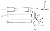
次に、本発明の第2実施形態について図3に基づいて説明する。本第2実施形態は、上記第1実施形態に比較して、シュラウド4の第1の端部41の形状が異なるものである。上記第1実施形態と同様の部分については同一の符号を付して説明を省略する。
(Second Embodiment)
Next, a second embodiment of the present invention will be described with reference to FIG. The second embodiment is different from the first embodiment in the shape of the
図3は、本第2実施形態係るクーリングモジュールの要部を示す拡大断面図である。図3に示すように、シュラウド4の第1の端部41は、コンデンサ1と反対側に屈曲する屈曲部41aを有している。また、屈曲部41aとモジュレータ13との間には、第1の隙間14が設けられている。
FIG. 3 is an enlarged cross-sectional view showing a main part of the cooling module according to the second embodiment. As shown in FIG. 3, the
屈曲部41aにおけるモジュレータ13に対向する部位は、先端に向かって厚みが減少する曲面形状、すなわちR形状(円弧曲面状)に形成されている。具体的には、屈曲部41aにおけるモジュレータ13に対向する部位は、角が丸くなっている。このとき、モジュレータ13の表面も曲面形状になっているため、第1の隙間14は湾曲面をなして広がるベルマウス形状になっている。
A portion of the
以上説明したように、シュラウド4における第1の端部41の屈曲部41aを先端に向かって厚みが減少する曲面形状に形成することで、第1の隙間14から送風機3に流入する空気は、屈曲部41aの曲面形状に沿ってスムーズにガイドされるとともに、モジュレータ13の表面形状に沿ってスムーズにガイドされる。これにより、送風機3作動時の騒音を低減することが可能となる。
As described above, the air flowing into the blower 3 from the
(他の実施形態)
なお、上記各実施形態では、熱交換器としてコンデンサ1を適用した例を説明したが、これに限らず、他の種類の熱交換器を適用してもよい。
(Other embodiments)
In each of the above embodiments, an example in which the capacitor 1 is applied as a heat exchanger has been described.
なお、上記各実施形態では、モジュレータ13を円筒状に形成し、第1、第2のヘッダタンク12a、12bを楕円筒状に形成したが、これらの形状に限らず、例えば角柱状等、他の形状に形成してもよい。
In each of the above embodiments, the
1…コンデンサ(熱交換器)、3…送風機、4…シュラウド、13…モジュレータ、14…第1の隙間、41…第1の端部。 DESCRIPTION OF SYMBOLS 1 ... Condenser (heat exchanger), 3 ... Blower, 4 ... Shroud, 13 ... Modulator, 14 ... 1st clearance, 41 ... 1st edge part.
Claims (5)
前記熱交換器(1)の空気流れ下流側に配置され、前記熱交換器(1)に空気を供給する送風機(3)と、
前記送風機(3)を保持するとともに、前記熱交換器(1)から前記送風機(3)に至る空気通路を形成するシュラウド(4)とを備え、
前記送風機(3)は前記熱交換器(1)よりも車両後方側に配置され、
前記シュラウド(4)の空気流れ上流側の端部(41、42)は、前記熱交換器(1)のうち前記コア部(11)の側方に配置される側方部(12a、13)の最前面よりも車両後方側に位置しており、
前記シュラウド(4)の空気流れ上流側の端部(41、42)と前記側方部(12a、13)との間には、隙間(14、15)が設けられており、
前記シュラウド(4)は、空気流れ下流側から空気流れ上流側へ向かって車両幅方向寸法が次第に拡大する形状であり、
前記シュラウド(4)の空気流れ上流側部分は、前記側方部(12a、13)の表面に沿って車両前方側に延びており、
前記シュラウド(4)の空気流れ上流側の端部(41、42)には、車両幅方向に広がる曲面が形成されており、
前記隙間(14、15)は、空気流れ上流側に向かって車両幅方向に広がっていることを特徴とするクーリングモジュール。 A heat exchanger (1) having a core (11) for exchanging heat between the passing air and the heat medium;
A blower (3) disposed on the downstream side of the air flow of the heat exchanger (1) and supplying air to the heat exchanger (1) ;
Holds the blower (3), and a shroud (4) for forming an air passage leading to the blower (3) from the heat exchanger (1),
The blower (3) is disposed on the vehicle rear side of the heat exchanger (1),
The air flow upstream end portions (41, 42) of the shroud (4) are side portions (12a, 13) arranged on the side of the core portion (11) in the heat exchanger (1). Is located on the rear side of the vehicle from the forefront,
A gap (14 , 15 ) is provided between the end (41 , 42 ) of the air flow upstream side of the shroud (4) and the side part (12a, 13) ,
The shroud (4) has a shape in which the vehicle width direction dimension gradually increases from the air flow downstream side toward the air flow upstream side,
The air flow upstream portion of the shroud (4) extends to the vehicle front side along the surface of the side portion (12a, 13),
A curved surface extending in the vehicle width direction is formed at the end (41 , 42 ) on the upstream side of the air flow of the shroud (4),
The said clearance gap (14 , 15 ) is a cooling module characterized by spreading in the vehicle width direction toward the air flow upstream.
前記付属部品(13)は、前記コンデンサ(1)により凝縮された前記冷媒を気液分離するモジュレータ(13)であり、
前記モジュレータ(13)の表面形状により前記シュラウド(4)側に突出する曲面が構成されていることを特徴とする請求項4に記載のクーリングモジュール。 The heat exchanger is a condenser (1) for exchanging heat between the refrigerant circulating in the refrigeration cycle and air to condense the refrigerant,
The accessory part (13) is a modulator (13) for gas-liquid separation of the refrigerant condensed by the condenser (1) ,
Cooling module according to claim 4, characterized in that curved surface convex toward the shroud (4) side is constituted by the surface shape before Symbol modulator (13).
Priority Applications (1)
| Application Number | Priority Date | Filing Date | Title |
|---|---|---|---|
| JP2005338043A JP4655902B2 (en) | 2005-11-24 | 2005-11-24 | Cooling module |
Applications Claiming Priority (1)
| Application Number | Priority Date | Filing Date | Title |
|---|---|---|---|
| JP2005338043A JP4655902B2 (en) | 2005-11-24 | 2005-11-24 | Cooling module |
Publications (2)
| Publication Number | Publication Date |
|---|---|
| JP2007147092A JP2007147092A (en) | 2007-06-14 |
| JP4655902B2 true JP4655902B2 (en) | 2011-03-23 |
Family
ID=38208713
Family Applications (1)
| Application Number | Title | Priority Date | Filing Date |
|---|---|---|---|
| JP2005338043A Expired - Fee Related JP4655902B2 (en) | 2005-11-24 | 2005-11-24 | Cooling module |
Country Status (1)
| Country | Link |
|---|---|
| JP (1) | JP4655902B2 (en) |
Families Citing this family (1)
| Publication number | Priority date | Publication date | Assignee | Title |
|---|---|---|---|---|
| US20110061405A1 (en) * | 2009-09-16 | 2011-03-17 | Keihin Corporation | Vehicular air conditioner equipped with vehicle shutter device, and failure determining method for vehicle shutter device |
Citations (4)
| Publication number | Priority date | Publication date | Assignee | Title |
|---|---|---|---|---|
| JPH01162033U (en) * | 1988-05-06 | 1989-11-10 | ||
| JPH0777044A (en) * | 1993-08-31 | 1995-03-20 | Caterpillar Inc | Low noise cooler |
| JPH11129935A (en) * | 1997-10-29 | 1999-05-18 | Aisin Seiki Co Ltd | Front end module for vehicle |
| JP2002303467A (en) * | 2001-04-03 | 2002-10-18 | Denso Corp | Mounting cooling structure for liquid receiver integrated refrigerant condenser |
-
2005
- 2005-11-24 JP JP2005338043A patent/JP4655902B2/en not_active Expired - Fee Related
Patent Citations (4)
| Publication number | Priority date | Publication date | Assignee | Title |
|---|---|---|---|---|
| JPH01162033U (en) * | 1988-05-06 | 1989-11-10 | ||
| JPH0777044A (en) * | 1993-08-31 | 1995-03-20 | Caterpillar Inc | Low noise cooler |
| JPH11129935A (en) * | 1997-10-29 | 1999-05-18 | Aisin Seiki Co Ltd | Front end module for vehicle |
| JP2002303467A (en) * | 2001-04-03 | 2002-10-18 | Denso Corp | Mounting cooling structure for liquid receiver integrated refrigerant condenser |
Also Published As
| Publication number | Publication date |
|---|---|
| JP2007147092A (en) | 2007-06-14 |
Similar Documents
| Publication | Publication Date | Title |
|---|---|---|
| JP5821795B2 (en) | Heat exchanger | |
| JP2000220983A (en) | Fin for heat exchanger | |
| JP2002372389A (en) | Heat exchanger | |
| JP2006284107A (en) | Heat exchanger | |
| JP2005188799A (en) | Heat exchanger for vehicle | |
| JP2008155739A (en) | Air guide for vehicle | |
| JP2007101158A (en) | Heat exchanger | |
| JP4655902B2 (en) | Cooling module | |
| JP2009109183A (en) | Tube for heat exchanger | |
| JP2008069756A (en) | Cooling system for vehicle | |
| JP4592992B2 (en) | Heat exchanger | |
| JP2007315619A (en) | Heat exchanger | |
| JP2007024334A (en) | Heat exchanger | |
| JP2005321151A (en) | Heat exchanger | |
| JP4665706B2 (en) | Cooling module | |
| JP5187047B2 (en) | Tube for heat exchanger | |
| JP2005156000A (en) | Heat exchanger | |
| JP5115263B2 (en) | Motorcycle heat exchanger | |
| JP2007003183A (en) | Heat exchanger | |
| JP4613832B2 (en) | Heat exchanger | |
| JP2006162136A (en) | Duplex heat exchanger | |
| JP2007055522A (en) | Front lower structure of vehicle | |
| JP2007170317A (en) | Cooling module | |
| JP2005083647A (en) | Core structure of heat exchanger | |
| JP6787301B2 (en) | Heat exchanger tube and heat exchanger |
Legal Events
| Date | Code | Title | Description |
|---|---|---|---|
| A621 | Written request for application examination |
Free format text: JAPANESE INTERMEDIATE CODE: A621 Effective date: 20071212 |
|
| A977 | Report on retrieval |
Free format text: JAPANESE INTERMEDIATE CODE: A971007 Effective date: 20100610 |
|
| A131 | Notification of reasons for refusal |
Free format text: JAPANESE INTERMEDIATE CODE: A131 Effective date: 20100727 |
|
| A521 | Written amendment |
Free format text: JAPANESE INTERMEDIATE CODE: A523 Effective date: 20100917 |
|
| TRDD | Decision of grant or rejection written | ||
| A01 | Written decision to grant a patent or to grant a registration (utility model) |
Free format text: JAPANESE INTERMEDIATE CODE: A01 Effective date: 20101130 |
|
| A01 | Written decision to grant a patent or to grant a registration (utility model) |
Free format text: JAPANESE INTERMEDIATE CODE: A01 |
|
| A61 | First payment of annual fees (during grant procedure) |
Free format text: JAPANESE INTERMEDIATE CODE: A61 Effective date: 20101213 |
|
| FPAY | Renewal fee payment (event date is renewal date of database) |
Free format text: PAYMENT UNTIL: 20140107 Year of fee payment: 3 |
|
| R151 | Written notification of patent or utility model registration |
Ref document number: 4655902 Country of ref document: JP Free format text: JAPANESE INTERMEDIATE CODE: R151 |
|
| FPAY | Renewal fee payment (event date is renewal date of database) |
Free format text: PAYMENT UNTIL: 20140107 Year of fee payment: 3 |
|
| R250 | Receipt of annual fees |
Free format text: JAPANESE INTERMEDIATE CODE: R250 |
|
| R250 | Receipt of annual fees |
Free format text: JAPANESE INTERMEDIATE CODE: R250 |
|
| R250 | Receipt of annual fees |
Free format text: JAPANESE INTERMEDIATE CODE: R250 |
|
| S802 | Written request for registration of partial abandonment of right |
Free format text: JAPANESE INTERMEDIATE CODE: R311802 |
|
| R350 | Written notification of registration of transfer |
Free format text: JAPANESE INTERMEDIATE CODE: R350 |
|
| R250 | Receipt of annual fees |
Free format text: JAPANESE INTERMEDIATE CODE: R250 |
|
| R250 | Receipt of annual fees |
Free format text: JAPANESE INTERMEDIATE CODE: R250 |
|
| R250 | Receipt of annual fees |
Free format text: JAPANESE INTERMEDIATE CODE: R250 |
|
| LAPS | Cancellation because of no payment of annual fees |