JP4655876B2 - Vehicle indicator instrument - Google Patents
Vehicle indicator instrument Download PDFInfo
- Publication number
- JP4655876B2 JP4655876B2 JP2005307532A JP2005307532A JP4655876B2 JP 4655876 B2 JP4655876 B2 JP 4655876B2 JP 2005307532 A JP2005307532 A JP 2005307532A JP 2005307532 A JP2005307532 A JP 2005307532A JP 4655876 B2 JP4655876 B2 JP 4655876B2
- Authority
- JP
- Japan
- Prior art keywords
- pointer
- light
- dial
- instrument
- vehicle
- Prior art date
- Legal status (The legal status is an assumption and is not a legal conclusion. Google has not performed a legal analysis and makes no representation as to the accuracy of the status listed.)
- Expired - Fee Related
Links
Images


Classifications
-
- B—PERFORMING OPERATIONS; TRANSPORTING
- B60—VEHICLES IN GENERAL
- B60K—ARRANGEMENT OR MOUNTING OF PROPULSION UNITS OR OF TRANSMISSIONS IN VEHICLES; ARRANGEMENT OR MOUNTING OF PLURAL DIVERSE PRIME-MOVERS IN VEHICLES; AUXILIARY DRIVES FOR VEHICLES; INSTRUMENTATION OR DASHBOARDS FOR VEHICLES; ARRANGEMENTS IN CONNECTION WITH COOLING, AIR INTAKE, GAS EXHAUST OR FUEL SUPPLY OF PROPULSION UNITS IN VEHICLES
- B60K2360/00—Indexing scheme associated with groups B60K35/00 or B60K37/00 relating to details of instruments or dashboards
- B60K2360/60—Structural details of dashboards or instruments
- B60K2360/68—Features of instruments
- B60K2360/698—Pointers of combined instruments
- B60K2360/6992—Light conducting pointers
Landscapes
- Details Of Measuring Devices (AREA)
- Instrument Panels (AREA)
Description
本発明は、たとえば自動車等の車両の運転席に設置される車両用指針計器に関するものであり、特に指針が発光表示される発光指針を備えるものに関する。 The present invention relates to a vehicular pointer instrument installed in a driver's seat of a vehicle such as an automobile, for example, and particularly relates to a vehicular pointer instrument provided with a light emitting pointer on which a pointer is displayed.
従来の車両用指針計器として、文字盤の表面側に配置された導光性指針を、文字盤にその端部から光を入射する光源からの光により文字盤を介して照明する構造のものがある(特許文献1参照)。 As a conventional indicating instrument for a vehicle, the placed light-guiding pointer on the surface side of the dial, those with light from a light source incident light from the end portion on the face of the structure to be illuminated through the dial Yes (see Patent Document 1).
この車両用指針計器においては、導光性指針の底面に導光性指針の長手方向に長さを有する溝部を設け、この溝部が光源からの光を反射して視認される。特に溝部の底部に対応する線状部分が溝部の他の部分よりも高輝度に見える。すなわち明るく光る線が指針として視認される。
上述の従来の車両用指針計器において、導光性指針の長手方向に直交する方向の断面形状は略長方形を成している。導光性指針の回動角度位置によっては、視認者から導光性指針の側面が見える。このとき、導光性指針の底面に設けられた溝部の壁面が導光性指針の側面を透かして見えると、指針として視認される輝線のほかに、それと平行にやや幅の広い明るい線が同時に見えることになり、車両用指針計器の見映えが低下する。 In the above-described conventional pointer instrument for a vehicle, the cross-sectional shape in the direction orthogonal to the longitudinal direction of the light guide pointer is substantially rectangular. Depending on the rotation angle position of the light guide pointer, the side of the light guide pointer can be seen by the viewer. At this time, if the wall surface of the groove provided on the bottom surface of the light guide pointer is seen through the side surface of the light guide pointer, in addition to the bright line visible as the pointer, a bright line that is slightly wider in parallel with it As a result, the appearance of the pointer instrument for the vehicle is degraded.
ところで、明るく光って見える部分の幅を広げて指針としての視認性を高めるためには、導光性指針の底面に設けられた溝の幅を広げる必要がある。この場合、溝部の縁が導光性指針の側面に接近することになり、溝部の壁面が導光性指針の側面を透かしてより一層見え易くなり、したがって、車両用指針計器の見映えが一層低下する可能性がある。 By the way, in order to widen the width of the brightly shining portion and increase the visibility as a pointer, it is necessary to increase the width of the groove provided on the bottom surface of the light guide pointer. In this case, the edge of the groove portion approaches the side surface of the light guide pointer, and the wall surface of the groove portion becomes easier to see through the side surface of the light guide pointer, and thus the appearance of the vehicle pointer instrument is further improved. May be reduced.
本発明は、上記の問題点に鑑みなされたもので、車両用指針計器の構成に工夫を凝らして、指針の視認性が良好、且つ斬新な見映えの車両用指針計器を提供することを目的とする。 The present invention has been made in view of the above-mentioned problems, and has been devised for the configuration of a pointer instrument for a vehicle, and an object thereof is to provide a pointer instrument for a vehicle with good visibility of the pointer and a novel appearance. And
本発明は上記目的を達成する為、以下の技術的手段を採用する。 In order to achieve the above object, the present invention employs the following technical means.
本発明の請求項1に記載の車両用指針計器は、文字盤と、光源と、文字盤に沿いその表面側にて回動可能に支持される導光性材質からなる指針とを備えた車両用指針計器であって、指針は、その底面に指針の長手方向に沿って形成された光反射部と底面と反対側の面である前面に光反射部に対向して設けられた凸レンズ部と、前面の幅方向における凸レンズ部の両側に設けられた遮光部とを備え、光源からの光を文字盤の前面側且つ文字盤の指針の回動範囲外から文字盤に沿って指針の側面に向けて照射する導光板であって、指針の回動範囲外において文字盤の前面側へリング状に突き出した部分に円筒面状の出射面を有し、光源からの光を出射面の全域から文字盤の表面に沿って文字盤の中心に向けて出射して、指針の側面に入射させる導光板が、設けられることを特徴としている。 According to a first aspect of the present invention, there is provided a vehicular pointer instrument including a dial, a light source, and a pointer made of a light guide material that is rotatably supported on the surface side along the dial. A pointer instrument for a pointer, a light reflecting portion formed along a longitudinal direction of the pointer on a bottom surface thereof, and a convex lens portion provided on a front surface which is a surface opposite to the bottom surface, facing the light reflecting portion; A light-shielding portion provided on both sides of the convex lens portion in the width direction of the front surface, and the light from the light source is directed to the side surface of the dial along the dial from the front side of the dial and outside the rotation range of the dial of the dial A light guide plate that emits light toward the front surface of the dial face outside the turning range of the pointer, and has a cylindrical surface to emit light from the entire surface of the light exit surface. A guide that exits along the surface of the dial toward the center of the dial and enters the side of the pointer. Plates, is characterized in that it is provided.
このような構成によれば、光反射部の幅を小さくして光反射部が指針の側面を透かして見えることを防止しつつ、凸レンズ部で光反射部の拡大虚像を結像させて視認させることで発光指針の幅を広げて指針としての視認性高めることができる。また、凸レンズ部の両側に設けた遮光部により指針の発光部分の輪郭をくっきりと際立たせることができるので、車両指針計器の見映えを斬新なものにできる。 According to such a configuration, the light reflecting portion is reduced in width to prevent the light reflecting portion from seeing through the side surface of the pointer, and an enlarged virtual image of the light reflecting portion is formed on the convex lens portion to be visually recognized. Thus, the width of the light emission pointer can be widened to improve the visibility as a pointer. Further, it is possible to highlight To clear the contours of the light emitting portion of the pointer by the light shielding portion provided on both sides of the convex lens portion, the appearance of the vehicle indicating instrument to those novel.
本発明の請求項2に記載の車両用指針計器は、指針の前面における幅寸法は底面における幅寸法よりも大きく且つ視認方向から見て底面の幅方向の輪郭線は前面の幅方向の輪郭線の内側に位置することを特徴としている。
In the vehicular pointer instrument according to
このような構成によれば、指針の長手方向に直交する方向の断面形状は視認者側が長辺且つ文字盤側が短辺の台形となる。このため、指針の側面は、従来の車両指針計器のような文字盤に対する垂直面ではなく、指針の前面から底面に向かうに連れて幅方向内側に向かって傾斜する斜面となる。したがって、指針の側面は指針の回動角度によらず視認者からはほとんど見えなくなる。すなわち、光反射部が指針の側面を透かして見えることを確実に防止することができる。 According to such a configuration, the cross-sectional shape in the direction orthogonal to the longitudinal direction of the pointer is a trapezoid having a long side on the viewer side and a short side on the dial side. Therefore, the side surface of the guide is not a plane perpendicular to the face, such as a conventional vehicle indicating instrument, a surface inclined inward in the width direction taken to toward the bottom surface from the front of the pointer. Therefore, the side surface of the pointer is hardly visible to the viewer regardless of the rotation angle of the pointer. That is, it is possible to reliably prevent the light reflecting portion from being seen through the side surface of the pointer.
本発明の請求項3に記載の車両用指針計器は、光反射部は底面に設けられた凹部であることを特徴としている。 In the vehicular pointer instrument according to claim 3 of the present invention, the light reflecting portion is a recess provided on the bottom surface.
このような構成によれば、指針に入射した光は凹部の壁面で反射し、その反射光が指針として視認されるので、指針の見映えをきらきらと輝くような見映えとして、車両用指針計器の見映えを斬新なものにできる。 According to such a configuration, the light incident on the pointer is reflected by the wall surface of the recess, and the reflected light is visually recognized as the pointer. Therefore, the pointer instrument for the vehicle can be seen as if the appearance of the pointer shines brightly. The appearance of can be made novel.
本発明の請求項4に記載の車両用指針計器は、光反射部は底面に設けられた拡散反射層であることを特徴としている。
The pointer instrument for a vehicle according to
このような構成によれば、指針に入射した光は拡散反射層で反射し、その反射光が指針として視認されるので、指針の見映えを全体が均一な明るさのソフトな見映えとして、車両用指針計器の見映えを斬新なものにできる。 According to such a configuration, the light incident on the pointer is reflected by the diffuse reflection layer, and the reflected light is visually recognized as the pointer, so that the appearance of the pointer is a soft appearance with uniform brightness as a whole, Appearance of the pointer instrument for vehicles can be made novel.
本発明の請求項5に記載の車両用指針計器は、光源は文字盤の背後に配置され光源が発する光の一部は文字盤の透過照明に用いられることを特徴としている。 The pointer instrument for a vehicle according to claim 5 of the present invention is characterized in that a light source is disposed behind the dial and a part of light emitted from the light source is used for transmitted illumination of the dial.
このような構成によれば、指針および文字盤を共通の光源からの光で照明することにより、車両用指針計器の部品点数、コストを低減することができる。 According to such a configuration, the number of parts and the cost of the pointer instrument for a vehicle can be reduced by illuminating the pointer and the dial with light from a common light source.
以下、本発明による車両用指針計器を、自動車に搭載されるコンビネーションメータに適用した場合を例に図面に基づいて説明する。 Hereinafter, an example in which the pointer instrument for a vehicle according to the present invention is applied to a combination meter mounted on an automobile will be described with reference to the drawings.
(第1実施形態)
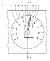
図1は、本発明の第1実施形態によるコンビネーションメータ1の部分正面図である。図1においては、タコメータT部を示している。
(First embodiment)
FIG. 1 is a partial front view of a
図2は、図1中のII−II線断面図である。図2において、左側が運転席側であり、コンビネーションメータ1は、左方から視認される。
2 is a cross-sectional view taken along line II-II in FIG. In FIG. 2, the left side is the driver's seat side, and the
図3は、図2中のIII−III線断面図である。 3 is a cross-sectional view taken along line III-III in FIG.
図4は、図3中のIV矢視図である。 4 is a view taken along arrow IV in FIG.
図5は、本発明の第1実施形態によるコンビネーションメータ1の電気回路構成を説明する模式図である。
FIG. 5 is a schematic diagram for explaining an electric circuit configuration of the
コンビネーションメータ1は、自動車の運転席前方の運転者から視認可能な位置に設置されている。タコメータTは、このコンビネーションメータ1内に形成され、当該自動車のエンジン回転速度を指針の回動角度により指示するものである。
The
以下に、コンビネーションメータ1の構成、すなわちタコメータTの構成について説明する。
Below, the structure of the
タコメータTは、大きくは、文字盤2、発光ダイオード4からの光を導いて文字盤3および指針7を照明する導光板3、指針7を回転させるムーブメント6等から構成されている。
Tachometer T is large,
文字盤2は、透光性材質、たとえば無色透明のポリカーボネート樹脂あるいはアクリル樹脂等の薄板から、図1に示すように、円形に形成されている。文字盤2は、エンジン回転速度を表す表示意匠としての「1」、「2」等の数字2aおよび目盛2b備えている。数字2aおよび目盛2bは、文字盤2の表面2c(図2において左側の面)に印刷あるいはホットスタンプ等を施すことにより形成されている。すなわち、数字2aおよび目盛2b以外の部分に不透光性着色層あるいは半透光性着色層を設けると共に、数字2aおよび目盛2bを透明なままとする、あるいは半透光性着色層を設ける等の処理を施してある。これにより、文字盤2の裏側に配置される後述する発光ダイオード4が点灯されると、それが発する光により文字盤2は透過照明されて、数字2aおよび目盛2bが発光表示される。文字盤2の中央部には、後述するムーブメント6のシャフト6aあるいは指針7のボス部を挿通させるための貫通孔2dが設けられている。指針7の回動範囲はこの貫通孔2dとほぼ同軸上の円形(正確には扇型)となるが、文字盤2の外周は、上述した指針7の回動範囲の外側に位置している。
The
文字盤2の背後には、図2に示すように、光源である発光ダイオード4が配置されている。発光ダイオード4としては、たとえば発光色が白色の白色発光ダイオードが用いられている。
As shown in FIG. 2, a
文字盤2の背後には、図2に示すように、発光ダイオード4が発する光を文字盤2の前面側且つ文字盤2の指針7の回動範囲外へ導いて文字盤2の表面2cに沿って指針7の側面7eに向けて照射すると同時に、発光ダイオード4が発する光を文字盤2の裏面に導いて文字盤2を透過照明する導光板3が配置されている。導光板3は、たとえば無色透明のポリカーボネート樹脂あるいはアクリル樹脂等から、文字盤2と同心上の円盤状に形成されている。導光板3の外周側は、図2に示すように、文字盤2の前面側にリング状に突き出しており、この突き出し部分には、図2に示すように、出射面3bが形成されている。出射面3bは円筒面状に形成され、その直径は文字盤2の直径とほぼ等しく形成されている。すなわち、文字盤2の外周縁が円筒面状の出射面3bに嵌合している。導光板3の裏面、つまり文字盤2と反対側の面の中央部付近には、図2に示すように、発光ダイオード4が発する光を導光板3内へ導入する受光部3aが設けられている。受光部3aは、本発明の第1実施形態によるコンビネーションメータ1においては、略球面状に形成されている。これにより、発光ダイオード4が発する光の大部分を導光体3の反射面3cに導くことができる。受光部3aは、発光ダイオード4に対向して設けられている。発光ダイオード4から発せられた光は、図2中において矢印で示すように進行して、導光体3内を経て、一部は出射面3bから出射し文字盤2の表面2cに沿って文字盤2の中心に向けて進行する。また、一部は導光体3内で反射を繰り返して文字盤2の文字2aおよび目盛2bから出射してこれらを透過照明する。受光部3aの個数、つまり発光ダイオード4の個数は、文字盤2の全ての文字2aおよび目盛2bが均一な明るさで発光表示され、且つ出射面3bから文字盤2の中心に向けて出射する光量が円筒面状の出射面3bの全域に亘って均一であるように設定されている。
Behind the
すなわち、本発明の第1実施形態によるコンビネーションメータ1では、発光ダイオード4を、指針7の照明と文字盤2の照明との両方の用途に利用している。
That is, in the
文字盤2の背後には、図2に示すように、指針7を回動させるムーブメント6が配置されている。ムーブメント6は、ステッピングモータ、あるいは交差コイル式回転機等の電気アクチュエータからなり、外部からの電気信号(タコメータTの場合は、エンジンの回転速度信号)に対応した角度だけシャフト6aを回動させるものである。ムーブメント6のシャフト6aの先端には、図2に示すように、指針7が固定されている。
A
指針7は、透光性材料、たとえばアクリル樹脂等により形成されている。指針7は、図2に示すように、ボス部7hを介してムーブメント6のシャフト6aに固定されている。
The
指針7の文字盤2側の面である底面7aには、図3に示すように、指針7の長手方向(図1において上下方向、図3においては紙面垂直方向)に沿って形成された光反射部としての反射面7bが設けられている。反射面7bは、図3に示すように、2面設けられている。すなわち、底面7aに断面V字上の凹部を設け、その2つの壁面が反射面7bとなっている。上述した導光板3の出射面3bから出射し文字盤2の表面2cに沿って進行してきた光が指針7の側面7eから指針7内に入射すると、図3中に矢印で示すように、この光は反射面7bで反射して図3中における上方に進行する。これにより、反射面7bが明るく発光して視認される。
The bottom 7a is a surface of the
指針7の文字盤2と反対側の面である前面7cには、図3に示すように、反射面7bに対向して設けられた凸レンズ部である凸レンズ面7dが設けられている。反射面7bは、運転者の視認方向、すなわち図3における上下方向において、凸レンズ面7dの焦点Fと凸レンズ面7dとの間に配置されている。これにより、運転者が指針7を見たときに、すなわち、図3において指針7の上方から指針7を見たときに、指針7の背後に結像された反射面7bの拡大虚像を視認する。
The front 7c is a surface opposite to the
指針7の前面7cにおいて、凸レンズ面7dの両側には、図3に示すように、遮光部である遮光層8が設けられている。遮光層8は、たとえば遮光性塗料をホットスタンプあるいは印刷等により施して形成されている。本発明の第1実施形態によるコンビネーションメータ1においては、艶消し黒色層が施されている。これにより、指針7、すなわち反射面7bの拡大虚像の輪郭をくっきりと際立たせることができるので、車両指針計器の見映えを斬新なものにできる。
On the
指針7において、図3に示すように、前面7cの幅寸法W2は底面7aの幅寸法W1よりも大きく形成されている。同時に、視認方向から見て(図3の上方から見て)底面7aの幅方向の輪郭線7gは、図4に示すように、前面7cの輪郭線7fの内側に位置している。これにより、指針7の断面形状は、図3に示すように、視認者側が長辺且つ文字盤2側が短辺の台形となる。したがって、指針7の側面7eは、従来の車両指針計器のような文字盤に対する垂直面ではなく、指針7の前面7cから底面7aに向かうに連れて幅方向内側に向かって傾斜する斜面となっている。指針7の断面形状を上述したような形状としたことにより、指針7の側面7eは指針7の回動角度によらず視認者からはほとんど見えなくなる。
In the
発光ダイオード4、ムーブメント6は、図2に示すように、文字盤2の裏側(図2において右側)に配置されたプリント基板5に実装されている。プリント基板5は、たとえばガラスエポキシ基板等からなり、タコメータTを含むコンビネーションメータ1の電気回路部を形成している。
As shown in FIG. 2, the
プリント基板5には、発光ダイオード4の点灯・消灯制御、ムーブメント6の駆動制御を行なうコントローラ10が実装されている。コントローラ10は、たとえばマイクロコンピュータ等から構成されている。
On the printed circuit board 5, a
以上説明した、文字盤2、外周リング3、導光板3、プリント基板5、ムーブメント6等は、図2に示すように、樹脂材料から成形されるケーシング11内に収容保持されている。
Described above, the
また、文字盤2の前面側には、図2に示すように、略枠状の見返し板12が装着され、さらに見返し板12の先端部には透明カバー13が装着されている。見返し板12は、たとえば樹脂材料から形成されている。透明カバー13は、透明な樹脂の薄板あるいはガラス等から形成されている。見返し板12および透明カバー13は、コンビネーションメータ1の見映えを整えると同時に、コンビネーションメータ1内部への埃、水分等の侵入を防止している。
Further, as shown in FIG. 2, a substantially frame-shaped facing
一方、ケーシング11の背後には、図2に示すように、ロアカバー14が装着されている。ロアカバー14は、たとえば樹脂材料から形成されている。
On the other hand, a
次に、以上説明した、本発明の第1実施形態によるコンビネーションメータ1の電気回路構成および作動について、図5に基づいて説明する。
Next, the electrical circuit configuration and operation of the
図4の電気回路構成図に示すように、コントローラ10には、バッテリ17から電力が常時供給されている。また、コントローラ10は、イグニッションスイッチ16が、その作動状態(ONまたはOFF)を検出可能に接続されている。
As shown in the electric circuit configuration diagram of FIG. 4, power is constantly supplied from the
コントローラ10には、当該自動車のエンジン回転速度を検出するエンジン回転センサ15が検出信号を入力可能に接続されている。
An
一方、コントローラ10には、その制御対象である、発光ダイオード4、ムーブメント6が接続されている。
On the other hand, the
(1)イグニッションスイッチ16がONされた場合。
(1) When the
運転者によりイグニッションスイッチ16がONされると、コントローラ10はイグニッションスイッチ16がONされたことを検知して、コンビネーションメータ1の表示制御作動を開始する。
When the
コントローラ10は、発光ダイオード4を点灯させ、同時に、エンジン回転センサ15からの検出信号に基づきムーブメント6を駆動してシャフト6aを所定角度、すなわち当該自動車のエンジン回転速度に対応する角度に回動させる。これにより、文字盤2の文字2aおよび目盛2bが発光ダイオード4からの光により透過照明されて発光表示される。同時に、指針7、数字2aおよび目盛2bによってエンジン回転速度が指示される。
The
(2)イグニッションスイッチ16がOFFされた場合。
(2) When the
運転者によりイグニッションスイッチ16がOFFされると、コントローラ10は、そのことを検知して、発光ダイオード4を消灯状態させる。同時に、コントローラ10は、ムーブメント6の駆動を停止する。
When the
次に、本発明の第1実施形態によるコンビネーションメータ1の特徴である指針7の形状が視認性におよぼす作用効果について説明する。
Next, the operation and effect of the shape of the
本発明の第1実施形態によるコンビネーションメータ1の指針7においては、底面7aに設けた反射面7bを前面7cに設けた凸レンズ面7dを透して視認する構成としている。すなわち、運転者は、凸レンズ面7dの背後に結像される反射面7bの拡大虚像を視認する。これにより、指針7としての良好な視認性を確保しつつ反射面7dの大きさ、特には指針7の幅方向寸法を必要最小限度に小さくできるので、従来の車両用指針計器において指針の側面を透して反射部が見えてしまい、車両用指針計器の見映えが低下するという不具合を防止できる。
In the
本発明の第1実施形態によるコンビネーションメータ1の指針7においては、前面7cの幅寸法W2を底面7aの幅寸法W1よりも大きく形成し、且つ視認方向から見て底面7aの幅方向の輪郭線7gを前面7cの輪郭線7fの内側に位置させている。すなわち、指針7の断面形状を視認者側が長辺且つ文字盤2側が短辺の台形としている。このため、指針7の側面7eは、従来の車両指針計器のような文字盤に対する垂直面ではなく、指針7の前面7cから底面7aに向かうに連れて幅方向内側に向かって傾斜する斜面となっており、指針7の回動角度によらず視認者からはほとんど見えなくなる。言い換えると、運転者が指針7を見たときに、側面7eを透して反射面7dが見えることがない。これにより、従来の車両用指針計器において指針の側面を透して反射部が見えてしまい、車両用指針計器の見映えが低下するという不具合を確実に防止できる。
In the
本発明の第1実施形態によるコンビネーションメータ1の指針7においては、前面7cの凸レンズ面7dの両側に遮光層8を設けている。これにより、指針7、すなわち反射面7bの拡大虚像の輪郭をくっきりと際立たせることができるので、コンビネーションメータ1の見映えを斬新なものにできる。
In the
(第2実施形態)
図6は、本発明の第2実施形態によるコンビネーションメータ1の部分拡大図であり、図1中のIII−III線断面図に相当する。
(Second Embodiment)
FIG. 6 is a partially enlarged view of the
本発明の第2実施形態によるコンビネーションメータ1は、本発明の第1実施形態によるコンビネーションメータ1に対して、指針7が備える光反射部の構成を変更している。本発明の第2実施形態によるコンビネーションメータ1では、光反射部として底面7aに、図6に示すように、反射層7jを設けている。反射層7jは、白色塗料をホットスタンプあるいは印刷等により施して指針7の長手方向に延びる帯状に形成されている。
The
導光板3の出射面3bから出射し文字盤2の表面2cに沿って進行してきた光が指針7の側面7eから指針7内に入射すると、この光は反射層7jで反射して図6における上方に向かって、つまり視認者に向かって進行する。したがって、本発明の第2実施形態によるコンビネーションメータ1においても、運転者は、指針7の背後に結像された反射層7jの拡大虚像を視認する。
When light that has exited from the
本発明の第2実施形態によるコンビネーションメータ1においても、本発明の第1実施形態によるコンビネーションメータ1の場合と同様の効果、すなわち、側面7eを透して反射面7dが見えることをなくして、従来の車両用指針計器において指針の側面を透して反射部が見えて車両用指針計器の見映えが低下するという不具合を確実に防止できる、という効果が得られる。
Also in the
なお、以上説明した本発明の第1実施形態によるコンビネーションメータ1においては、光反射部として底面7aに2つの反射面7bを設けているが、反射面7bの個数を2つに限る必要はなく、3つ以上でもよい。たとえば、底面7aに設ける凹部の断面形状をコ字状として凹部の3つの壁面を反射面7bとしてもよい。さらに、反射面7bの形状を平面とする必要はなく、たとえば、底面7aに設ける凹部の断面形状を半円形状として、反射面7bを1つの円筒面としてもよい。
In the
また、以上説明した本発明の第2実施形態によるコンビネーションメータ1においては、反射層7jを白色塗料層としているが、白色に限る必要はなく、たとえば銀色、黄色あるいは朱色等であってもよい。さらには、反射層7jを塗料層に限る必要はなく、たとえばシボ面として形成する、あるいは他の材質、たとえば金属の薄板等を貼付してもよい。
Moreover, in the
また、以上説明した本発明の第1、第2実施形態によるコンビネーションメータ1においては、指針7の前面7cの遮光層8を黒色層としているが、黒色に限る必要はなく他の色であってもよい。さらには、他の材質たとえば金属の薄板等を貼付してもよい。
Moreover, in the
また、以上説明した本発明の第1、第2実施形態によるコンビネーションメータ1においては、文字2b、目盛3aおよび指針7照明用の光源として発光ダイオード4を用いているが、他の種類の光源、たとえば電球、放電管、ELパネル等を用いても良い。
In the above first aspect of the present invention described, in the
また、以上説明した本発明の第1、第2実施形態によるコンビネーションメータ1においては、発光ダイオード4を、文字2b、目盛3aおよび指針7照明用の共通の光源として用いているが、導光体3を分割して、発光ダイオード4を指針7の照明のみに用いて、文字盤2の照明用に新たな光源を設置してもよい。
The first of the present invention described above, in the
また、以上説明した本発明の第1、第2実施形態によるコンビネーションメータ1においては、指針計器をタコメータTとしているが、他の計器、たとえば走行速度を指示するスピードメータあるいは残存燃料量を表示する燃料計等としてもよい。
Further, in the
1 コンビネーションメータ(車両用指針計器)
2 文字盤
2a 数字
2b 目盛
2c 表面
2d 貫通孔
3 導光板
3a 受光部
3b 出射面
3c 反射面
4 発光ダイオード(光源)
5 プリント基板
6 ムーブメント
6a シャフト
7 指針
7a 底面
7b 反射面(光反射部、凹部)
7c 前面
7d 凸レンズ部
7e 側面
7f 輪郭線
7g 輪郭線
7h ボス部
7j 反射層(光反射部)
8 遮光層(遮光部)
9 遮光キャップ
10 コントローラ
11 ケーシング
12 見返し板
13 透明カバー
14 ロアカバー
15 エンジン回転センサ
16 イグニッションスイッチ
17 バッテリ
F 焦点
T タコメータ
W1 幅寸法
W2 幅寸法
1 Combination meter (vehicle pointer instrument)
2
5 Printed
8 Shading layer (shading part)
9
Claims (5)
光源と、
前記文字盤に沿いその表面側にて回動可能に支持される導光性材質からなる指針とを備えた車両用指針計器であって、
前記指針は、その底面に前記指針の長手方向に沿って形成された光反射部と前記底面と反対側の面である前面に前記光反射部に対向して設けられた凸レンズ部と、
前記前面の幅方向における前記凸レンズ部の両側に設けられた遮光部とを備え、
前記光源からの光を文字盤の前面側且つ前記文字盤の前記指針の回動範囲外から前記文字盤に沿って前記指針の側面に向けて照射する導光板であって、前記指針の回動範囲外において前記文字盤の前面側へリング状に突き出した部分に円筒面状の出射面を有し、前記光源からの光を前記出射面の全域から前記文字盤の表面に沿って前記文字盤の中心に向けて出射して、前記指針の側面に入射させる導光板が、設けられることを特徴とする車両用指針計器。 Dial,
A light source;
A pointer instrument for a vehicle comprising a pointer made of a light guide material supported rotatably on the surface side along the dial,
The pointer is a light reflecting portion formed along the longitudinal direction of the pointer on the bottom surface thereof, and a convex lens portion provided on the front surface which is a surface opposite to the bottom surface, facing the light reflecting portion;
A light shielding portion provided on both sides of the convex lens portion in the width direction of the front surface,
A light guide plate that irradiates light from the light source toward the side of the pointer along the dial from the front side of the dial and out of the range of rotation of the pointer of the dial. Outside the range, the dial has a cylindrical exit surface that protrudes in a ring shape toward the front side of the dial, and light from the light source extends from the entire exit surface along the surface of the dial. A guide instrument for a vehicle, characterized in that a light guide plate that emits toward the center of the guide and enters the side face of the pointer is provided .
Priority Applications (1)
| Application Number | Priority Date | Filing Date | Title |
|---|---|---|---|
| JP2005307532A JP4655876B2 (en) | 2005-10-21 | 2005-10-21 | Vehicle indicator instrument |
Applications Claiming Priority (1)
| Application Number | Priority Date | Filing Date | Title |
|---|---|---|---|
| JP2005307532A JP4655876B2 (en) | 2005-10-21 | 2005-10-21 | Vehicle indicator instrument |
Publications (2)
| Publication Number | Publication Date |
|---|---|
| JP2007114116A JP2007114116A (en) | 2007-05-10 |
| JP4655876B2 true JP4655876B2 (en) | 2011-03-23 |
Family
ID=38096435
Family Applications (1)
| Application Number | Title | Priority Date | Filing Date |
|---|---|---|---|
| JP2005307532A Expired - Fee Related JP4655876B2 (en) | 2005-10-21 | 2005-10-21 | Vehicle indicator instrument |
Country Status (1)
| Country | Link |
|---|---|
| JP (1) | JP4655876B2 (en) |
Families Citing this family (1)
| Publication number | Priority date | Publication date | Assignee | Title |
|---|---|---|---|---|
| JP5182216B2 (en) * | 2009-05-18 | 2013-04-17 | 株式会社デンソー | Vehicle display device |
Family Cites Families (3)
| Publication number | Priority date | Publication date | Assignee | Title |
|---|---|---|---|---|
| JPS5966198U (en) * | 1982-10-25 | 1984-05-02 | 日本精機株式会社 | Pointer illumination device |
| JPS62184418U (en) * | 1986-05-15 | 1987-11-24 | ||
| JP2959440B2 (en) * | 1995-06-30 | 1999-10-06 | 日本精機株式会社 | Indicating instrument |
-
2005
- 2005-10-21 JP JP2005307532A patent/JP4655876B2/en not_active Expired - Fee Related
Also Published As
| Publication number | Publication date |
|---|---|
| JP2007114116A (en) | 2007-05-10 |
Similar Documents
| Publication | Publication Date | Title |
|---|---|---|
| JP5851471B2 (en) | Pointer-type instrument | |
| JP4853212B2 (en) | Display device | |
| JP4977403B2 (en) | Vehicle display device | |
| JP4437550B2 (en) | Vehicle indicator instrument | |
| JP5045403B2 (en) | Pointer instrument | |
| JP2007212311A (en) | Pointer instrument | |
| JP4835380B2 (en) | Display device | |
| JP4175308B2 (en) | Vehicle indicator instrument | |
| JP4858228B2 (en) | Pointer instrument | |
| JP4675746B2 (en) | Instrument dial | |
| JP4075843B2 (en) | Vehicle indicator instrument | |
| JP4655876B2 (en) | Vehicle indicator instrument | |
| JP2006118892A (en) | Pointer instrument | |
| JP4600234B2 (en) | Vehicle instrument | |
| JP4218604B2 (en) | Vehicle indicator instrument | |
| JP4667896B2 (en) | Pointer instrument | |
| JP4655900B2 (en) | Vehicle instrument | |
| JP4661719B2 (en) | Instrument | |
| JP5245683B2 (en) | Instrument | |
| JP4933069B2 (en) | Vehicle indicator instrument | |
| JP2007017410A (en) | Luminescence pointer for measuring instrument and measuring instrument provided with it | |
| JP2007256194A (en) | Pointer instrument for vehicle | |
| JP2005345287A (en) | Pointer meter | |
| JP5513166B2 (en) | Vehicle display device | |
| JP2006113024A (en) | Pointing instrument |
Legal Events
| Date | Code | Title | Description |
|---|---|---|---|
| A621 | Written request for application examination |
Free format text: JAPANESE INTERMEDIATE CODE: A621 Effective date: 20071115 |
|
| A977 | Report on retrieval |
Free format text: JAPANESE INTERMEDIATE CODE: A971007 Effective date: 20100212 |
|
| A131 | Notification of reasons for refusal |
Free format text: JAPANESE INTERMEDIATE CODE: A131 Effective date: 20100316 |
|
| A521 | Request for written amendment filed |
Free format text: JAPANESE INTERMEDIATE CODE: A523 Effective date: 20100507 |
|
| TRDD | Decision of grant or rejection written | ||
| A01 | Written decision to grant a patent or to grant a registration (utility model) |
Free format text: JAPANESE INTERMEDIATE CODE: A01 Effective date: 20101130 |
|
| A01 | Written decision to grant a patent or to grant a registration (utility model) |
Free format text: JAPANESE INTERMEDIATE CODE: A01 |
|
| A61 | First payment of annual fees (during grant procedure) |
Free format text: JAPANESE INTERMEDIATE CODE: A61 Effective date: 20101213 |
|
| FPAY | Renewal fee payment (event date is renewal date of database) |
Free format text: PAYMENT UNTIL: 20140107 Year of fee payment: 3 |
|
| FPAY | Renewal fee payment (event date is renewal date of database) |
Free format text: PAYMENT UNTIL: 20140107 Year of fee payment: 3 |
|
| R250 | Receipt of annual fees |
Free format text: JAPANESE INTERMEDIATE CODE: R250 |
|
| LAPS | Cancellation because of no payment of annual fees |