JP4655324B2 - Vibration motor, positioning device, and vibration motor control method - Google Patents
Vibration motor, positioning device, and vibration motor control method Download PDFInfo
- Publication number
- JP4655324B2 JP4655324B2 JP2000080749A JP2000080749A JP4655324B2 JP 4655324 B2 JP4655324 B2 JP 4655324B2 JP 2000080749 A JP2000080749 A JP 2000080749A JP 2000080749 A JP2000080749 A JP 2000080749A JP 4655324 B2 JP4655324 B2 JP 4655324B2
- Authority
- JP
- Japan
- Prior art keywords
- vibrator
- vibration
- drive signal
- input
- relative motion
- Prior art date
- Legal status (The legal status is an assumption and is not a legal conclusion. Google has not performed a legal analysis and makes no representation as to the accuracy of the status listed.)
- Expired - Lifetime
Links
Images


Description
【0001】
【発明の属する技術分野】
本発明は、振動モータ、位置決め装置および振動モータの制御方法に関する。具体的には、本発明は、駆動信号が入力されて振動を発生する振動子を備える振動モータと、例えば光ファイバ等の情報伝送路の切換装置に適用するのに好適な、例えば超音波モータ等の振動モータを用いた位置決め装置と、振動モータの制御方法とに関する。
【0002】
【従来の技術】
一般的に、例えば直流サーボモータ等のサーボモータを位置決め装置の駆動源として用いて位置決め対象物を目標位置に位置決めするには、目標位置との位置偏差を基にサーボループを構成することにより、位置偏差を0とするようにモータの駆動制御を行う。そして、位置偏差が0となった時点で、サーボ制御を行ったまま、モータの駆動を停止する。この際に、サーボモータの停止位置が外乱により変動すると、発生した位置偏差を直ちに零とするべくモータが動作する。このため、サーボモータを用いた位置決め装置では、位置決め対象物が目標位置の極近傍に存在しているにもかかわらず、常に電力を消費することになる。
【0003】
一方、振動モータは、一般的に、2種の圧電素子に、互いの位相が(π/2)異なるとともに所定の周波数を有する連続波からなる2相の駆動信号(交流電圧)をそれぞれ入力することによって、これらの圧電素子が装着された弾性体に位相が異なる2つの定在波を励振し、これらの定在波が合成されて弾性体の駆動力取出部に発生した楕円運動を利用して、駆動力取出部に加圧接触する相対運動部材を摩擦駆動する。この種の振動モータとして、超音波の振動域を利用した超音波モータが知られているため、以降の説明ではこの超音波モータを例にとる。
【0004】
この超音波モータは、目標位置に停止した後は、圧電素子への電気入力を停止するだけでドリフトもなく、さらに外力にも乱されずにその位置で停止し続けるという、いわゆる自己保持性を有する。このため、この超音波モータを位置決め装置の駆動源として用いることが有望視されている。
【0005】
超音波モータを位置決め装置の駆動源として用いて位置決め対象物を目標位置に位置決めするには、従来のサーボモータの制御がそのまま流用されていた。
【0006】
【発明が解決しようとする課題】
しかし、従来のサーボモータの制御をそのまま超音波モータに流用すると、位置偏差が零に収束するようにフィードバック制御が行われるため、目標位置の近傍では位置偏差が振動的に増減し、目標位置から所定の距離の範囲に設定された位置決め許容範囲に入るための時間が長時間化してしまう。
【0007】
図11は、従来のサーボモータの制御をそのまま超音波モータに流用した場合の、指令位置、位置決め対象物の検出速度および位置偏差(指令位置と現位置との偏差)と、時間との関係の一例を示すグラフである。
【0008】
図11にグラフで示すように、超音波モータが時刻t0 に起動され、指令位置に追従しながら位置決め対象物は目標位置へ向けて移動し、時刻t1 で位置決め許容範囲P内に存在するにもかかわらず、サーボ制御のため、超音波モータは時刻t2 、t3 およびt4 において目標位置を通過し、この振動が減衰した時刻t5 において、ようやく位置決め許容範囲Pに停止する。このため、位置決め許容範囲に達した時から(t5 −t1 )時間が経過するまでの停止時間が長時間化してしまう。停止時間の長時間化は、位置決め装置、例えば光ファイバ切換端子駆動装置の重要な技術課題である。
【0009】
本発明の目的は、目標位置に短時間で停止することができる例えば超音波モータ等の振動モータと、その制御方法と、この振動モータを用いて位置決め対象物を目標位置に短時間で停止させることができる位置決め装置とを提供することである。
【0010】
【課題を解決するための手段】
本発明は、振動モータの振動子又は相対運動部材が、目標位置から所定の距離の範囲に設定された位置決め許容範囲に達した時以降にもサーボ制御を継続するのではなくて、振動子への駆動信号の入力を禁止することにより、上述した課題を解決できるという新規かつ重要な知見に基づくものである。
【0011】
請求項1の発明は、駆動信号を入力されて振動を発生する振動子と、この振動子に加圧接触して相対運動を発生する相対運動部材と、相対運動部材又は振動子に固定され、相対運動に伴って駆動される可動部が、目標停止位置から所定の距離の範囲に設定された位置決め許容範囲に達した時以降であり、かつ、可動部の速度が、振動子への駆動信号の入力を停止した際に発生する機械的振動によって変位する振動子又は相対運動部材の振幅が位置決め許容範囲以下となる速度に低下した時以降に、振動子への駆動信号の入力を禁止する駆動制御装置とを備えることを特徴とする振動モータを提供する。
【0012】
請求項2の発明は、請求項1に記載された振動モータにおいて、駆動制御装置が、振動子への前記駆動信号の入力を停止した際に発生する機械的振動によって変位する振動子又は相対運動部材の振幅が位置決め許容範囲の1/2となる速度に低下した時以降に、振動子への前記駆動信号の入力を禁止することを特徴とする。
【0014】
請求項3の発明では、請求項1又は請求項2に記載された振動モータと、この振動モータにより駆動される可動ステージとを備えることを特徴とする位置決め装置である。
【0015】
請求項4の発明では、駆動信号を入力されて振動を発生する振動子又はこの振動子に加圧接触して相対運動を発生する相対運動部材に固定され、前記の相対運動に伴って駆動される可動部が、目標停止位置から所定の距離の範囲に設定された位置決め許容範囲に達した時以降であり、かつ、可動部の速度が、振動子への駆動信号の入力を停止した際に発生する機械的振動によって変位する振動子又は相対運動部材の振幅が位置決め許容範囲以下となる速度に低下した時以降に、振動子への駆動信号の入力を禁止することを特徴とする振動モータの制御方法を提供する。
さらに、請求項5の発明は、請求項4に記載された振動モータの制御方法において、振動子への駆動信号の入力を停止した際に発生する機械的振動によって変位する振動子又は相対運動部材の振幅が位置決め許容範囲の1/2となる速度に低下した時以降に、振動子への駆動信号の入力を禁止することを特徴とする。
【0016】
【発明の実施の形態】
(第1実施形態)
以下、本発明にかかる振動モータを用いた位置決め装置の実施の形態を、添付図面を参照しながら詳細に説明する。なお、以降の実施の形態の説明では、振動モータとして超音波の振動域を利用した超音波モータを用いるとともに、本発明にかかる位置決め装置を、光ファイバの切換装置に適用した場合を例にとる。
【0017】
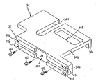
図1は、本実施形態の位置決め装置30を、一部が透視されるとともに簡略化された状態で示す斜視図である。また、図2は図1におけるA矢視図であり、図3は図1におけるB矢視図である。
【0018】
図1〜図3にそれぞれ示すように、本実施形態の位置決め装置30は、超音波モータ33と可動ステージ34とを有する。以下、本実施形態の位置決め装置30のこれらの構成要素について、順次説明する。
【0019】
〔超音波モータ33〕
超音波モータ33は、振動子31、移動子32及び振動子固定部材42を有する。以下、これらについて順次説明する。
【0020】
(i)振動子31
図4は、本実施形態における振動子31及び移動子32それぞれの構成を示す斜視図である。また、図5は、振動子31の説明図であり、図5(A)は上面図、図5(B)は側面図、図5(C)は振動子31に発生する二つの異なる振動L1及びB4それぞれの波形例を示す説明図である。
【0021】
図1〜図5にそれぞれ示すように、本実施形態で用いる振動子31は、弾性体35と、弾性体35の一方の平面に装着された圧電体36とを備える。
弾性体35は、例えば鉄鋼、ステンレス鋼、リン青銅又はエリンバー材等といった共振先鋭度が大きな金属材料により構成されることが望ましく、矩形平板状に形成される。また、弾性体35の各部の寸法は、発生する1次の縦振動L1及び4次の屈曲振動B4それぞれの固有振動数fL1、f B4が略一致するように、設定される。
【0022】
弾性体35の一方の平面には、圧電体36が例えば接着により装着される。また、弾性体35の他方の平面には、弾性体35の幅方向に2本の溝部が相対運動方向(図2、図4及び図5それぞれにおける左右方向)に関して所定距離だけ離れて設けられる。これらの溝部に、横断面形状が矩形である各棒型の、高分子材等を主成分とした摺動部材が嵌め込まれて装着され、突起状に突出して装着される。高分子材としては、PTFE、ポリイミド樹脂、ポリアセタール、PPSさらにはPEEK等の高分子材料が例示される。
【0023】
そして、この摺動部材が駆動力取出部37a、37bとして機能する。したがって、弾性体35はこれら摺動部材からなる駆動力取出部37a、37bを介して移動子32に加圧接触する。
【0024】
また、図3に示すように、各駆動力取出部37a、37bは、いずれも、振動子31の幅方向に二つに分割され、分割されたそれぞれの駆動力取出部37a、37a’、37b、37b’が振動子31の幅方向の端部側に配置される。このように、本実施形態では、各駆動力取出部37a、37bは、それぞれが2個の摺動材により構成される。
【0025】
これらの駆動力取出部37a、37bは、図5(B)及び図5(C)に示すように、弾性体35に発生する4次の屈曲振動B4の4つの腹位置l1 〜l4 のうちの外側に位置する二つの腹位置l1 、l4 に一致する位置にそれぞれ設けられる。なお、駆動力取出部37a、37bは、屈曲振動B4の二つの腹位置l1 、l4 に正確に一致する位置に設けられる必要はなく、これらの腹位置l1 、l4 の近傍に設けられていてもよい。
【0026】
圧電体36は、本実施形態ではPZT(チタンジルコン酸鉛)からなる一枚の薄板状の圧電素子により構成される。この圧電体36には、図4及び図5に示すように、A相の駆動信号VA が入力される入力領域36a、36cと、A相の駆動信号とは位相が約(π/2)ずれたB相の駆動信号VB が入力される入力領域36b、36dとが形成される。各入力領域36a〜36dは、いずれも、図5(A)〜図5(C)に示すように、弾性体35に発生する屈曲振動B4の5つの節位置n1 〜n5 により区画された4つの領域に連続して形成される。すなわち、駆動信号の入力により変形する各入力領域36a〜36dが、いずれも、不動点である節位置n1 〜n5 を跨がない。そのため、入力領域36a〜36dの変形が節位置n1 〜n5 によって抑制されることがない。これにより、各入力領域36a〜36dに入力された電気エネルギを最大の効率で弾性体35の変形、すなわち機械エネルギへ変換することができる。
【0027】
また、屈曲振動B4の節位置n2 、n4 には、振動子31が発生する縦振動L1により電気エネルギを出力する検出領域36p、36p’が設けられる。これにより、振動子31が発生する縦振動L1の振動状態がモニタされる。
【0028】
そして、図4、図5(A)及び図5(B)に示すように、各入力領域36a〜36dと各検出領域36p、36p’とは、それぞれの表面を、銀電極38a〜38d、38p、38p’により覆われる。これにより、各入力領域36a〜36dへ独立して駆動信号を入力したり、各検出領域36p、36p’から独立して検出信号を出力することができる。なお、図面を簡略化して理解を容易にするため、図1〜図3では、いずれも、銀電極38a〜38d、38p、38p’は省略してある。
【0029】
各銀電極38a〜38dには、電気エネルギの授受を行うためのリード線39a〜39dが半田付けされて接続され、また、銀電極38p、38p’には、同じくリード線(図示しない。)が半田付けされて接続されている。
【0030】
なお、本実施形態では、図5(A)に示すように、振動子31はその平面の中央部を中心として点対称となるように、形成される。これにより、各駆動力取出部37a、37a’、37b、37b’に発生する楕円運動を略同じ形状とすることができ、相対運動方向の反転に伴う駆動差が殆ど解消される。
【0031】
図7を参照しながら後述するように、位置決め装置30の駆動制御装置61から、圧電体36の入力領域36a、36cには、縦振動L1及び屈曲振動B4それぞれの固有振動数に略一致した周波数を有するA相の駆動信号VA が入力される。また、入力領域36b、36dには、A相の駆動信号とは(π/2)の位相差を有するB相の駆動信号VB が入力される。すると、図5(C)に示すように、弾性体35には、相対運動方向(図5における左右方向)へ振動する第1の振動である1次の縦振動L1と、この相対運動方向に直交する上下方向、すなわち振動子31と移動子32との加圧方向に平行な方向へ振動する第2の振動である4次の屈曲振動B4とが同時に発生する。
【0032】
発生した縦振動L1と屈曲振動B4とは合成されて、駆動力取出部37a、37a’と駆動力取出部37b、37b’とには、図5(B)に例示するように、互いの位相がπずれた楕円運動がそれぞれ発生する。これにより、振動子31は加圧接触する移動子32との間で、縦振動L1の振動方向への相対的な直線運動を発生する。なお、相対運動方向を逆向きにするには、B相の駆動信号が、A相の駆動信号に対して(−π/2)の位相差を有するように設定すればよい。
【0033】
このように、本実施形態の振動子31は、相対運動の方向へ振動する第1の振動である縦振動L1と、この第1の振動の振動方向と直交する方向へ振動する第2の振動である屈曲振動B4とを励振することにより、移動子32との間で直線的な相対運動を発生する、いわゆる異形モード縮退型の振動子である。
【0034】
(ii)移動子32
図1〜図5にそれぞれ示すように、本実施形態では、振動子31との間で相対運動を行う相対運動部材として、移動子32を用いる。図6は、移動子32及び可動ステージ34を抽出して示す斜視図である。
【0035】
移動子32は、ステンレス鋼、銅合金又はアルミニウム合金等からなっており、可動ステージ34の移動子取付面34aに3本の平小ねじ40により固定される。
【0036】
本実施形態では、図6に示すように、移動子32の振動子31との当接面のうちで、駆動力取出部37a、37a’及び駆動力取出部37b、37b’のいずれにも接触しない十字型の非接触部41cは、駆動力取出部37a、37a’及び駆動力取出部37b、37b’のいずれかに接触する接触部41a、41a’、41b、41b’よりも、肉薄に形成されている。これにより、移動子32の振動子31との当接面は、図1〜図4及び図6に示すように、十字型の溝状に形成される。すなわち、移動子32の振動子31との当接面の四隅部には、突起部41a〜41b’がそれぞれ形成される。なお、本実施形態では、後述するように、移動子32の振動子31との当接面に十字型の溝を形成しているが、この溝の部分を節に振動し難いようになっている。なぜなら、移動子32は、断面2次モーメントが大きいL型の断面形状を有する可動ステージ34の移動子取付面34aに装着されているため、移動子32には曲げ変形に伴った屈曲振動は発生しない。
【0037】
移動子32は、図1〜図3を参照しながら後述するように、振動子固定部材42により加圧支持された振動子31の駆動力取出部37a、37a’と駆動力取出部37b、37b’とに、突起部41a〜41b’を介して適当な加圧力で加圧接触して配置される。
【0038】
これにより、振動子31を起動すると、移動子32は、駆動力取出部37a、37a’と駆動力取出部37b、37b’とに互いの位相がπだけずれてそれぞれ発生した楕円運動によって、突起部41a〜41b’を介して駆動される。このため、移動子32は、後述するベース基板60上に固定されたリニアガイド55によって直線的に案内される可動ステージ34とともに、直線的に駆動される。このように、本実施形態では、固定配置された振動子31によって移動子32が直線的に駆動される。
【0039】
本実施形態では、移動子32の振動子31との当接面に十字型の溝が形成されることにより、位置決め装置30の移動系の一部をなす移動子32の軽量化が図られている。これにより、移動子32とともに移動する可動ステージ34の整定時間が短縮化される。
【0040】
また、移動子32の振動子31との接触面に、振動子31との接触状態を良好にするためにラップ加工による鏡面仕上を施す場合、本実施形態では、突起部41a〜41b’の底面だけにこのラップ加工を施せばよい。このため、ラップ加工の面積が低減され、ラップ加工による鏡面仕上の加工時間を短縮化することができる。
【0041】
さらに、突起部41a〜41b’それぞれは、いずれも振動子31よりも相当質量が小さいため、これら突起部41a〜41b’それぞれの固有振動数は、振動子31の超音波の振動数(例えば50kHZ程度)よりも高くなる。このため、振動子31が発生する振動が駆動力取出部37a、37a’及び駆動力取出部37b、37b’を介して突起部41a〜41b’に伝播されても、突起部41a〜41b’はいずれも、駆動を害するような振動(低周波の振動)が発生し難くなる。このため、振動子31が発生した振動により可動ステージ34が振動することも、抑制される。このため、可動ステージ34の振動が抑制され、可動ステージ34を高精度で位置決めすることができる。
【0042】
(iii)振動子固定部材42
図1〜図3に示すように、本実施形態の振動モータ30は、振動子固定部材42を有する。振動子固定部材42は、L型の水平断面形状を有するブロック体であり、アルミニウム合金やステンレス鋼等の金属材料からなる。この振動子固定部材42は、振動子支持部材43と振動子加圧部材44とを備える。
【0043】
図1〜図3に示すように、振動子支持部材43は、アルミニウム合金やステンレス鋼等の金属材料からなる薄板状部材であり、板厚の小さな屈曲部43aと、板厚が大きな支持部43bとを有する。屈曲部43aの一方の端部には二つの貫通孔が設けられており、振動子支持部材43は、これらの貫通孔をそれぞれ貫通する固定ねじ43cによって、振動子固定部材42の端面に固定される。
【0044】
また、支持部43bの振動子11側の平面には、ステンレス鋼製の二つの支持ピン45a、45bが、例えば接着や溶接等の適宜手段により固定される。そして、支持ピン45a、45bは、振動子11の両側面の長手方向の略中央部に形成された半円上の二つの切欠き部31a、31b(図5(A)参照。)に嵌め込まれて、例えば接着や溶接等の適宜手段により固定される。
【0045】
なお、振動子31の一方の平面に装着された圧電体36と支持部43bとの間には、例えばプラスチック等からなる絶縁部材46が挟まれた状態で配置されており、入力領域36b及び36cの短絡が防止される。
【0046】
振動子31は、振動子支持部材43によって、相対運動の方向(図2における左右方向)について拘束されるとともに、屈曲部43aが円弧状に屈曲変位することにより加圧方向(図2における上下方向)へ略直線的に微小に変位できるように、支持される。
【0047】
一方、図1〜図3に示すように、振動子加圧部材44は、四隅部に加圧用突起47a〜47dを有する板材である。加圧用突起47a〜47dを振動子加圧部材44の四隅部に配置したのは、電極38a〜38d、38p、38p’とリード線39a〜39dとの半田付けの盛り上がり部との干渉を防止するためである。加圧用突起47a及び47cは、振動子31に発生する屈曲振動B4の節位置n2 の位置と一致する位置に、また、加圧用突起47b及び47dは、振動子31に発生する屈曲振動B4の節位置n4 の位置と一致する位置に、それぞれ設けられて、振動子31に当接する。つまり、加圧用突起47a〜47dは、いずれも、屈曲振動B4の節位置n2 、n4 を跨ぐ位置に形成されている。
【0048】
また、振動子支持部材43の屈曲部43aには貫通孔43dが設けられており、振動子加圧部材44の加圧用突起47b及び47dは、いずれも、この貫通孔43dを貫通して振動子31に装着された圧電体36に当接する。これにより、振動子支持部材43と、振動子加圧部材44との接触が防止される。
【0049】
図2に示すように、振動子固定部材42の振動子加圧部材44側の平面の略中央部に設けられた収容孔42aには、加圧力発生部材48が装着される。本実施形態では、加圧力発生部材48としてコイルばねを用いた。なお、振動子固定部材42の加圧力発生部材48との当接部には、ねじ部材49がねじ止めされており、ねじ部材49のねじ込み深さを調節することにより、加圧力発生部材48が発生する加圧力を適宜調節できるように構成されている。
【0050】
加圧力発生部材48が発生した加圧力により、振動子加圧部材44は振動子31の方向へ付勢される。これにより、加圧用突起47a〜47dにより振動子31は、駆動力取出部37a〜37b’を介して、移動子32の突起部41a〜41b’と適宜加圧力で加圧接触する。
【0051】
振動子固定部材42は、2本の取付けねじ42bによってベース基板60に固定される。これにより、振動子31及び移動子32は、ベース基板60の表面から一定距離だけ離れて支持される。
【0052】
このように、本実施形態では、振動子支持部材43及び振動子加圧部材44を備える振動子固定部材42により、振動子31が支持される。
すなわち、本実施形態の超音波モータ33は、駆動力取出部を有する振動子31と、駆動力取出部を介して振動子31に加圧接触することによりこの振動子31との間で直線的な相対運動を行う移動子32と、振動子31を移動子32に加圧接触させる振動子固定部材42とを有する。
【0053】
なお、本実施形態では、振動子固定部材42に中継基板50が固定されている。中継基板50は、リード線39と、位置決め装置30の駆動制御装置61に接続されるリード線51とを接続し、駆動制御装置61からの駆動信号を圧電体36に入力する。また、この中継基板50を、例えばガラス、アルミナ、セラミック又はシリコーン等の熱伝導度が小さい絶縁材料により構成した場合には、この中継基板50に温度センサ(図示しない。)を設けて駆動時の振動子31の近辺の環境温度を検出し、この検出値を駆動制御装置61からの駆動信号のフィードバック制御因子とすることにより、より正確な制御を行うことができる。
【0054】
〔可動ステージ34〕
図1〜図3及び図6に示すように、本実施形態の位置決め装置30は、可動ステージ34を有する。
【0055】
可動ステージ34は、例えばアルミニウム合金のような軽金属材料により軽量に構成される。本実施形態では、この可動ステージ34は、移動子32が固定される第1の平面である移動子取付面34aと、移動子取付面34aと略直交する第2の平面である搭載面34bとを有し、図3に示すように、L字状に屈曲して形成される。このため、図3に示すように、相対運動の方向に対しての垂直な面を断面として見たときの断面二次モーメントが大きく、摺動面における曲げに対する剛性が高い。したがって、移動子取付面34aは、振動子31が発生する第2の振動である屈曲振動B4による加圧力を垂直に受けても、変形し難い。
【0056】
移動子取付面34aは、図6に示すように、移動子32を装着するための3本の平小ねじ40をネジ止めするためのネジ穴以外は何も設けられず、一様な面とされている。
【0057】
一方、搭載面34bは、振動子31及び移動子32の加圧方向、すなわち屈曲振動B4の振動方向と平行な方向へ向けて延設されている。
この搭載面34bの下面の略中央部には、4本のねじ52によってガイド53が固定される。ガイド53は、ベース基板60に相対運動の方向と平行な方向へ向けて敷設されたレール54に嵌合し、レール54とともにリニアガイド55を構成する。このため、可動ステージ34は、リニアガイド55により相対運動の方向と平行な方向へ移動自在に支持される。
【0058】
搭載面34bには、光ファイバ56aの切換端子56が搭載される。この切換端子56は、例えば樹脂材料により直方体状に形成され、入力側の光ファイバ56aの端部を貫通させた状態で固定されて、装着される。
【0059】
本実施形態では、光ファイバ56aとして、中心部に設けられた屈折率がn1 であるコアと、コアの外周に設けられた屈折率がn2 (n2 <n1 )のクラッディングと、クラッディングの外周に設けられたコアやクラッディングに比較して格段に光吸収の多い材料からなるジャケットとを有するステップ形光ファイバを用いた。
【0060】
また、ベース基板60に固定された支持台57に、4本の光ファイバ58aそれぞれの4つの切換端子58が、光ファイバ56aの切換端子56と同じ設置高さになるようにして搭載される。各切換端子58は、いずれも、例えば樹脂材料により直方体状に形成され、4本の光ファイバ58aの端部をそれぞれ貫通させた状態で固定されて、装着される。切換端子58それぞれの一つの端面には、各光ファイバ58aの端面が同一平面をなして、配置される。この光ファイバ58aは、光ファイバ56aと同様に、ステップ形光ファイバである。
【0061】
なお、図1〜図3では、図面を簡略化して理解を容易にするために、切換端子58が4つ並設された場合を示すが、本発明はこれに限られるものではなく、2つ、3つ又は5つ以上の切換端子が並設された場合にも、同様に適用される。
【0062】
なお、ベース基板60には、透過型のエンコーダ59の検出部を構成する発光部59a及び受光部59bが、可動ステージ34の縦フランジ34cに固定されたスケール部59cを挟んで、対向して配置される。このエンコーダ59により、可動ステージ34の現位置が検出される。検出値は、位置決め装置30の駆動制御装置61へ出力され、超音波モータ33の駆動が制御される。
【0063】
本実施形態では、可動ステージ34を、移動子取付面34a及び搭載面34bによりL字状に屈曲して形成することにより、剛性を高めてある。また、搭載面34bが移動子取付面34aに対して垂直に張り出している構造である。このため、搭載面34bに、軽量化のための切欠き部や中空部を設けても、移動子取付面34aの曲げ剛性を充分に保つことができ、振動モータ33のクラッチ機能による衝撃を受けても、移動子取付面34aが変形することに起因した振動が、搭載面34bに生じ難い(特に曲げ)構造である。したがって、本実施形態では、搭載面34bのうちで、切換端子56の搭載部及びガイド53装着部以外の部分、すなわち、受光部59bの上方に位置する部分と、発光部59aと支持台57との間とに、それぞれ中空部34d、切欠き部34eをそれぞれ設けてある。このため、本実施形態によれば、振動モータ33のクラッチ機能に起因した振動を可動ステージ34に生じることなく、可動ステージ34を軽量化することができる。
【0064】
なお、本実施形態では、図1〜図3及び図6に示すように、中空部34d及び切欠き部34eを、いずれも、リニアガイド55の装着部に関して振動子取付面34aと反対側に位置する可動ステージ34の平面に設けてあるため、可動ステージ34の重心位置を、リニアガイド55のレール54の直上に近づけることができる。これにより、停止の直前における可動ステージ34に作用するヨー慣性モーメントを低減できる。このため、本実施形態によれば、可動ステージ34をその重心回りに回転する変位を生じることなく停止でき、可動ステージ34の位置決め精度を向上できる。
【0065】
このように、可動ステージ34は、移動子32に固定されて振動子31と移動子32との加圧方向に略平行な方向へ向けて延設されるとともに、リニアガイド55により振動子31と移動子32との相対運動の方向と略平行な方向へ直線的に移動自在に支持される。
【0066】
図7は、本実施形態の位置決め装置30の駆動制御装置61の一例を示すブロック図である。また、図8は、この駆動制御装置61のCPU62のフローチャートである。
【0067】
駆動制御装置61のCPU62は、図8におけるステップ(以下、「S」と略記する。)1において上位指令装置63から目標位置、動作条件(加減速度や最高速度等)の指令を入力される。また、CPU62は、目標位置とエンコーダ59のカウンタ68からのカウント値との偏差に基づいてディジタル信号を出力する。そして、S2に移行する。
【0068】
S2において、CPU62は、エンコーダ59の検出値に基づいて、目標位置と現在位置との差である移動量を算出する。そして、S3に移行する。
S3において、CPU62は、S2において算出した移動量を、S1において入力された動作条件(加減速度や最高速度等)で移動した場合の動作速度プロファイルを設定する。
【0069】
図9は、設定された動作速度プロファイルおよび指令位置の一例を示すグラフである。図9にグラフにより示すように、S3において、時間に対する指令位置が決定される。そして、S4に移行する。
【0070】
S4において、CPU62は、駆動周波数を初期値f0 (共振周波数よりも高周波側)に設定し、図7におけるD/A変換器64にディジタル信号を出力する。D/A変換器64は、ディジタル信号をアナログ電圧信号に変換して、VCO65に出力する。VCO65は、D/A変換器64から入力されるアナログ電圧信号の電圧値に対応した二つの周波信号を発生し、増幅器66Aおよび移相器67に出力する。移相器67は、入力された周波信号の位相を(±π/2)ずらす。そして.増幅器66AからA相の駆動信号が入力領域36a、36cの銀電極38a、38cへ印加され、また、増幅器66BからB相の駆動信号が入力領域36b、36dの銀電極38b、38dへ印加される。これにより、振動子31は励振し、駆動力取出部37a〜37b’を介して加圧接触する移動子32と、この移動子32に固定された可動ステージ34とを、ともに直線的に駆動する。
【0071】
S5において、CPU62は、カウンタ68を介してエンコーダ59により可動ステージ34の駆動開始が確認されるまで、駆動周波数を低周波側へΔfずつ掃引する。そして、駆動開始が確認された後、S6に移行する。
【0072】
S6において、CPU62は、エンコーダ59の検出値に基づいて、各時点における指令位置と検出位置との偏差である偏差eを算出する。そして、S7に移行する。
【0073】
S7において、CPU62は、制御ゲインαを任意に設定し、S6において算出した偏差eに基づいて、駆動周波数fを設定する。そして、駆動周波数fを変更しながら偏差eが零となるように速度を変更する。そして、S8に移行する。なお、駆動周波数fを決定する方法は、これに限られず、偏差eを基にして、任意の式が設定可能である。
【0074】
S8において、CPU62は、検出位置が予め設定した位置決め許容範囲に到達したことを確認する。そして、到達していない場合にはS6に移行し、到達した場合にはS9に移行する。すなわち、S8においては、可動ステージ34が目標位置から所定の距離の範囲に設定された位置決め許容範囲に達したことが確認される。
【0075】
S9において、CPU62は、検出速度が予め設定した停止速度に到達したことを確認する。
ここで、超音波モータ33により駆動される可動ステージ34の停止時の運動を、粘性減衰力が作用するばね−質量系の1自由度系の振動に置き換えて考えると、質量をmとし、ばね定数をkとし、粘性減衰係数をcとすると、運動方程式は、(c/m) =2μ、p =√(k/m) とすると、下記(1)式となる。
【0076】
x''+2μx' +p2x=0 ・・・・・・・(1)
この(1)式を解くと、その解は、μ<0の場合、下記(2)式として与えられる。
【0077】
【数1】

【0078】
そして、S10において、CPU62は、振動子31への駆動信号の入力、すなわち駆動電圧の印加を禁止する信号を出力する。本実施形態では、駆動電源を遮断することにより、振動子31への駆動信号の入力を停止した。これにより、可動ステージ34は初期振幅aの減衰振動を行いながら停止する。しかし、可動ステージ34は位置決め許容範囲を逸脱しない。
【0079】
この本実施形態の位置決め装置30によれば、以下に列記する効果が奏せられる。
(1)可動ステージ34を、振動子31と移動子32との加圧方向に略平行な方向へ向けて延設された状態で移動子32に固定したため、振動子固定部材42、振動子31、移動子32及び可動ステージ34をいずれもこの方向について並設して配置できる。このため、ベース基板60に直交する方向に関する位置決め装置30の寸法をできるだけ抑制できる。このため、小型であることから小さな設置スペースにも設置することができる位置決め装置30を提供できる。
【0080】
(2)移動子32のうちの駆動力取出部37a〜37b’との非接触部41cの厚さを、駆動力取出部37a〜37b’との接触部41a〜41b’の厚さよりも小さくしたため、移動子32を軽量化できる。また、可動ステージ34に、中空部34d及び切欠き部34eを形成したため、可動ステージ34を軽量化できる。したがって、これらの相乗的効果により、移動子32及び可動ステージ34をともに軽量化でき、可動ステージ34の整定時間を短縮化することができる。
【0081】
(3)移動子32のうちの駆動力取出部37a〜37b’との非接触部41cの厚さを、駆動力取出部37a〜37b’との接触部41a〜41b’の厚さよりも小さくしたため、突起部41a〜41b’へのラップ加工の加工時間を低減できる。
【0082】
(4)移動子32のうちの駆動力取出部37a〜37b’との非接触部41cの厚さを、駆動力取出部37a〜37b’との接触部41a〜41b’の厚さよりも小さくしたため、振動子31が発生した振動に起因して可動ステージ34が振動することを抑制できる。また、可動ステージ34に、移動子32に固定される振動子取付け面34aと搭載面34bとを設けたため、搭載面34bに中空部34d及び切欠き部34eを形成しても、振動子31が発生した振動に起因して可動ステージ34が振動することを抑制できる。さらに、中空部34d及び切欠き部34eを、いずれも、リニアガイド55の装着部に関して振動子取付面34aと反対側に位置する可動ステージ34の平面に設けることにより、可動ステージ34をその重心回りに回転する変位を生じることなく停止できる。したがって、これらの相乗的効果により、可動ステージ34の位置決め精度を向上できる。
【0083】
(5)図10は、本実施形態により、可動ステージ34が目標位置の近傍に到達した時点で超音波モータ33の振動子31に対する駆動信号の入力を停止した場合に、可動ステージ34の検出速度および位置偏差(指令位置と現位置との偏差)と、時間との関係の一例を示すグラフである。
【0084】
図10にグラフで示すように、本超音波モータ33が時刻t0 に起動され、指令位置に追従しながら目標位置へ向けて移動し、駆動制御装置61から、位置決め許容範囲Pに到達するとともに所定の停止速度に低下した時刻t1 に、超音波モータ33の振動子31への駆動信号の入力を禁止する信号が出力される。この際、可動ステージ34に発生する振動は、位置決め許容範囲を逸脱しない振幅aの振動であるため、可動ステージ34は時刻t2 を経て、時刻t3 において、目標位置に停止する。
【0085】
このように、本実施形態では、可動ステージ34が、目標位置から所定の距離の範囲に設定された位置決め許容範囲に達した時以降にも、サーボ制御を継続するのではなくて、振動子31への駆動信号の入力を禁止するため、位置決め対象物である可動ステージ34および切換端子56を目標位置に短時間で停止させることができる。
【0086】
このため、本実施形態によれば、所望の目標位置に短時間で停止することができる例えば超音波モータ33と、その制御方法と、この超音波モータ33を用いて位置決め対象物である可動ステージ34および切換端子56を目標位置に短時間で停止させることができる位置決め装置30とを、いずれも提供することができる。
【0087】
また、さらに駆動信号の入力停止時までに、可動ステージ34の移動速度を十分に小さくしているため、停止時における可動ステージ34の振動振幅が十分小さくなっており、可動ステージ34の振動により信号停止時以降の可動ステージ34の移動は許容位置決め範囲から逸脱することはない。また、完全に可動ステージ34の振動が停止した時以降も超音波モータ33の自己保持力により可動ステージ34は動かないため駆動信号を入力する必要はない。
【0088】
(変形形態)
実施形態の説明では、振動モータが超音波モータである場合を例にとった。しかし、本発明は超音波モータには限定されず、超音波以外の他の振動域を利用した振動モータについても、等しく適用される。
【0089】
また、実施形態の説明では、本発明にかかる位置決め装置を光ファイバの切換装置に適用した場合を例にとった。しかし、本発明は光ファイバの切換装置には限定されず、各種の位置決め装置についても等しく適用される。
【0090】
また、実施形態の説明では、振動子と移動子との間で発生する相対運動の方向と略平行な方向へ振動する第1の振動である1次の縦振動と、振動子と移動子との加圧方向と略平行な方向へ振動する第2の振動である4次の屈曲振動とを励振する異形モード縮退型の振動子を用いた場合を例にとった。しかし、本発明で用いる振動子は縦振動及び屈曲振動それぞれの振動の次数には限定されない。例えば、1次の縦振動と2次の屈曲振動とを励振する振動子や、1次の縦振動と6次の屈曲振動とを励振する振動子、さらには3次の縦振動と8次の屈曲振動とを励振する振動子等も、同様に用いることができる。
【0091】
また、本発明で用いる振動子は、縦振動及び屈曲振動の組合せにも限定されず、この組合せ以外の異形モード縮退型の振動子や、同形モード縮退型の振動子であっても、同様に適用することができる。
【0092】
また、実施形態の説明では、振動子が圧電体を備える場合を例にとった。しかし、本発明は圧電体には限定されず、例えば電歪素子等の電気エネルギ及び機械エネルギの相互変換素子であれば、等しく適用することができる。
【0093】
また、実施形態の説明では、振動子が4つの駆動力取出部を有する場合を例にとった。しかし、本発明はこの形態には限定されず、例えば、弾性体の幅方向に2つの駆動力取出部が相対運動方向に関して所定距離だけ離れて設けられた場合であっても、等しく適用される。この場合、移動子の駆動力取出部との接触部は矩形の平面形状を呈することから、移動子の振動子との当接面には、各実施形態のような十字型の溝は形成されず、矩形平面形状の溝部が相対運動の方向の略中心部に形成される。
【0094】
また、実施形態の説明では、移動ステージに切欠き部及び中空部がともに形成された場合を例にとった。しかし、本発明はこの形態には限定されず、切欠き部及び中空部の一方が形成されていてもよい。
【0095】
また、実施形態の説明では、偏差が位置決め許容範囲に入り、かつ所定の速度に低下したタイミングで振動子への駆動信号の入力が禁止される場合を例にとった。しかし、本発明はこのタイミングには限定されず、このタイミング以降に振動子への駆動信号の入力を禁止するようにしてもよい。
【0096】
また、実施形態の説明では、偏差が位置決め許容範囲に入り、かつ所定の速度に低下したタイミングで振動子への駆動信号の入力が禁止される場合を例にとった。しかし、本発明はこの形態には限定されず、位置決め許容範囲へ到達した時点における速度が充分に小さく抑制されている場合には、所定の速度に低下していなくとも、位置決め許容範囲に入ったタイミングで、振動子への駆動信号の入力を禁止するようにしてもよい。
【0097】
また、実施形態の説明では、駆動電源を遮断することにより、駆動電圧の印加を禁止することとしたが、本発明はこの形態には限定されず、駆動電圧の印加を禁止できる手段であれば、いかなる手段であってもよい。
【0098】
また、実施形態の説明では、振動子を固定配置し、相対運動部材を可動ステージに設けた場合を例にとったが、本発明はこの形態には限定されず、例えば、相対運動部材を固定配置し、振動子を可動ステージに設けてもよい。
【0099】
さらに、各実施形態は、本発明を具現化した一例を示したものであり、本発明の作用効果を奏する範囲で様々な変形が可能である。
【0100】
【発明の効果】
本発明により、所望の停止位置に短時間で停止することができる例えば超音波モータ等の振動モータと、その制御方法と、この振動モータを用いて位置決め対象物を目標位置に短時間で停止させることができる位置決め装置とを提供できた。
【図面の簡単な説明】
【図1】実施形態の位置決め装置を、一部が透視されるとともに簡略化された状態で示す斜視図である。
【図2】図1におけるA矢視図である。
【図3】図1におけるB矢視図である。
【図4】実施形態における振動子及び移動子それぞれの構成を示す斜視図である。
【図5】実施形態における振動子の説明図であり、図5(A)は上面図、図5(B)は側面図、図5(C)は振動子に発生する二つの異なる振動L1及びB4それぞれの波形例を示す説明図である。
【図6】実施形態における移動子及び可動ステージを抽出して示す斜視図である。
【図7】実施形態の位置決め装置の駆動制御装置の一例を示すブロック図である。
【図8】実施形態の位置決め装置の駆動制御装置のCPUのフローチャートである。
【図9】実施形態において設定された動作速度プロファイルおよび指令位置の一例を示すグラフである。
【図10】実施形態により、可動ステージが目標位置の近傍に到達した時点で超音波モータの振動子に対する駆動信号の入力を停止した場合に、可動ステージの検出速度および位置偏差(指令位置と現位置との偏差)と、時間との関係の一例を示すグラフである。
【図11】従来のサーボモータの制御をそのまま超音波モータに流用した場合の、指令位置、位置決め対象物の検出速度および位置偏差(指令位置と現位置との偏差)と、時間との関係の一例を示すグラフである。
【符号の説明】
30 位置決め装置
31 振動子
32 移動子
33 超音波モータ
34 可動ステージ
61 駆動制御装置[0001]
BACKGROUND OF THE INVENTION
The present invention relates to a vibration motor, a positioning device, and a control method for the vibration motor. Specifically, the present invention is suitable for application to a vibration motor including a vibrator that receives a drive signal and generates vibration, and an information transmission path switching device such as an optical fiber, for example, an ultrasonic motor. The present invention relates to a positioning device using a vibration motor such as the above, and a control method of the vibration motor.
[0002]
[Prior art]
Generally, in order to position a positioning object at a target position using a servo motor such as a DC servo motor as a driving source of a positioning device, a servo loop is configured based on a positional deviation from the target position. Motor drive control is performed so that the positional deviation is zero. When the position deviation becomes zero, the motor drive is stopped while the servo control is being performed. At this time, if the stop position of the servo motor fluctuates due to disturbance, the motor operates to immediately make the generated position deviation zero. For this reason, in a positioning device using a servo motor, power is always consumed even though the positioning target is present in the immediate vicinity of the target position.
[0003]
On the other hand, a vibration motor generally inputs two-phase drive signals (alternating voltage) composed of continuous waves having different phases (π / 2) and having a predetermined frequency to two types of piezoelectric elements. Thus, two standing waves having different phases are excited in the elastic body to which these piezoelectric elements are mounted, and the elliptical motion generated in the driving force extraction portion of the elastic body by combining these standing waves is utilized. Thus, the relative motion member in pressure contact with the driving force extraction portion is friction driven. As this type of vibration motor, an ultrasonic motor using an ultrasonic vibration region is known, and this ultrasonic motor is taken as an example in the following description.
[0004]
After stopping at the target position, this ultrasonic motor has a so-called self-holding property that only stops the electrical input to the piezoelectric element, does not drift, and continues to stop at that position without being disturbed by external force. Have. For this reason, it is considered promising to use this ultrasonic motor as a driving source of the positioning device.
[0005]
In order to position an object to be positioned at a target position using an ultrasonic motor as a drive source of a positioning device, the control of a conventional servo motor is used as it is.
[0006]
[Problems to be solved by the invention]
However, if the conventional servo motor control is applied to the ultrasonic motor as it is, feedback control is performed so that the position deviation converges to zero, so that the position deviation vibrates in the vicinity of the target position. It takes a long time to enter the positioning tolerance set in the predetermined distance range.
[0007]
FIG. 11 shows the relationship between the command position, the detection speed of the positioning object and the position deviation (deviation between the command position and the current position), and time when the control of the conventional servo motor is directly applied to the ultrasonic motor. It is a graph which shows an example.
[0008]
As shown in the graph of FIG. 0 The positioning object moves toward the target position while following the command position, and the time t 1 The ultrasonic motor is at time t because of servo control despite being within the positioning tolerance P. 2 , T Three And t Four At the time t when the vibration is attenuated Five Then, it finally stops within the positioning allowable range P. For this reason, from the time when the positioning allowable range is reached (t Five -T 1 ) The stop time until the time elapses becomes longer. Increasing the stop time is an important technical problem of a positioning device, for example, an optical fiber switching terminal driving device.
[0009]
An object of the present invention is to, for example, a vibration motor such as an ultrasonic motor that can be stopped at a target position in a short time, a control method thereof, and a positioning object to be stopped at a target position in a short time using the vibration motor. It is to provide a positioning device that can.
[0010]
[Means for Solving the Problems]
The present invention does not continue servo control after the vibrator or relative motion member of the vibration motor reaches the positioning allowable range set in the range of the predetermined distance from the target position. This is based on a new and important finding that the above-described problem can be solved by prohibiting the input of the drive signal.
[0011]
The invention according to claim 1 is a vibrator that receives a drive signal to generate vibration, a relative motion member that generates a relative motion by pressurizing and contacting the vibrator, A movable part fixed to the relative motion member or vibrator and driven by relative motion Is after the positioning allowable range set in the range of the predetermined distance from the target stop position, and movable part When the speed of the vibrator decreases to a speed at which the amplitude of the vibrator or relative motion member that is displaced by mechanical vibration generated when the input of the drive signal to the vibrator is stopped falls below the allowable positioning range, the vibrator A vibration motor comprising: a drive control device that prohibits input of a drive signal to the motor.
[0012]
According to a second aspect of the present invention, in the vibration motor according to the first aspect, the drive control device includes: The amplitude of the vibrator or the relative motion member displaced by the mechanical vibration generated when the input of the drive signal to the vibrator is stopped becomes 1/2 of the positioning allowable range. The drive signal is prohibited from being input to the vibrator after the speed is reduced.
[0014]
Claim 3 In the invention of Claim 1 or claim 2 A positioning apparatus comprising: the vibration motor described in 1); and a movable stage driven by the vibration motor.
[0015]
According to a fourth aspect of the present invention, a vibrator that generates a vibration upon receiving a drive signal or a relative motion member that generates a relative motion by being in pressure contact with the vibrator. A movable part that is fixed to and driven by the relative movement Is after the positioning allowable range set in the range of the predetermined distance from the target stop position, and movable part When the speed of the vibrator decreases to a speed at which the amplitude of the vibrator or relative motion member that is displaced by mechanical vibration generated when the input of the drive signal to the vibrator is stopped falls below the allowable positioning range, the vibrator Provided is a vibration motor control method characterized by prohibiting input of a drive signal to the motor.
Furthermore, the invention according to
[0016]
DETAILED DESCRIPTION OF THE INVENTION
(First embodiment)
Embodiments of a positioning device using a vibration motor according to the present invention will be described below in detail with reference to the accompanying drawings. In the following description of the embodiments, an ultrasonic motor using an ultrasonic vibration region is used as the vibration motor, and the positioning device according to the present invention is applied to an optical fiber switching device. .
[0017]
FIG. 1 is a perspective view showing a
[0018]
As shown in FIGS. 1 to 3, the
[0019]
[Ultrasonic motor 33]
The
[0020]
(I)
FIG. 4 is a perspective view showing the configuration of each of the
[0021]
As shown in FIGS. 1 to 5, the
The
[0022]
A
[0023]
And this sliding member functions as drive
[0024]
Further, as shown in FIG. 3, each of the driving
[0025]
As shown in FIGS. 5B and 5C, these driving
[0026]
In the present embodiment, the
[0027]
Further, the node position n of the bending vibration B4 2 , N Four Are provided with
[0028]
As shown in FIG. 4, FIG. 5 (A) and FIG. 5 (B), the
[0029]
[0030]
In this embodiment, as shown in FIG. 5A, the
[0031]
As will be described later with reference to FIG. 7, from the
[0032]
The generated longitudinal vibration L1 and bending vibration B4 are combined, and the driving
[0033]
As described above, the
[0034]
(Ii)
As shown in FIGS. 1 to 5, in this embodiment, a moving
[0035]
The
[0036]
In the present embodiment, as shown in FIG. 6, of the contact surface of the moving
[0037]
As will be described later with reference to FIGS. 1 to 3, the moving
[0038]
As a result, when the
[0039]
In the present embodiment, by forming a cross-shaped groove on the contact surface of the moving
[0040]
In addition, in the present embodiment, when the
[0041]
Further, since each of the
[0042]
(Iii)
As shown in FIGS. 1 to 3, the
[0043]
As shown in FIGS. 1 to 3, the
[0044]
Further, two
[0045]
In addition, an insulating member 46 made of, for example, plastic is sandwiched between the
[0046]
The
[0047]
On the other hand, as shown in FIGS. 1 to 3, the
[0048]
Further, the bending
[0049]
As shown in FIG. 2, a pressurizing
[0050]
The
[0051]
The
[0052]
Thus, in this embodiment, the
That is, the
[0053]
In the present embodiment, the
[0054]
[Movable stage 34]
As shown in FIGS. 1 to 3 and 6, the
[0055]
The
[0056]
As shown in FIG. 6, the moving
[0057]
On the other hand, the mounting
A
[0058]
A switching
[0059]
In the present embodiment, the refractive index provided at the center of the
[0060]
In addition, the four
[0061]
1 to 3 show a case where four
[0062]
A
[0063]
In the present embodiment, the rigidity is enhanced by forming the
[0064]
In this embodiment, as shown in FIGS. 1 to 3 and 6, both the
[0065]
As described above, the
[0066]
FIG. 7 is a block diagram illustrating an example of the
[0067]
The CPU 62 of the
[0068]
In S <b> 2, the CPU 62 calculates a movement amount that is a difference between the target position and the current position based on the detection value of the
In S3, the CPU 62 sets an operation speed profile when the movement amount calculated in S2 is moved under the operation condition (acceleration / deceleration, maximum speed, etc.) input in S1.
[0069]
FIG. 9 is a graph showing an example of the set operation speed profile and command position. As shown by the graph in FIG. 9, in S3, the command position with respect to time is determined. Then, the process proceeds to S4.
[0070]
In S4, the CPU 62 sets the drive frequency to the initial value f. 0 The digital signal is outputted to the D /
[0071]
In S <b> 5, the CPU 62 sweeps the drive frequency to the low frequency side by Δf until the start of driving of the
[0072]
In S <b> 6, the CPU 62 calculates a deviation e that is a deviation between the command position and the detected position at each time point based on the detection value of the
[0073]
In S7, the CPU 62 arbitrarily sets the control gain α, and sets the drive frequency f based on the deviation e calculated in S6. Then, the speed is changed so that the deviation e becomes zero while changing the driving frequency f. Then, the process proceeds to S8. Note that the method for determining the drive frequency f is not limited to this, and an arbitrary expression can be set based on the deviation e.
[0074]
In S8, the CPU 62 confirms that the detection position has reached a preset positioning allowable range. If not reached, the process proceeds to S6, and if reached, the process proceeds to S9. That is, in S8, it is confirmed that the
[0075]
In S9, the CPU 62 confirms that the detection speed has reached a preset stop speed.
Here, when the motion at the stop of the
[0076]
x ″ + 2μx ′ + p 2 x = 0 (1)
When this equation (1) is solved, the solution is given as the following equation (2) when μ <0.
[0077]
[Expression 1]
[0078]
In S <b> 10, the CPU 62 outputs a drive signal input to the
[0079]
According to the
(1) Since the
[0080]
(2) Because the thickness of the
[0081]
(3) Because the thickness of the
[0082]
(4) Because the thickness of the
[0083]
(5) FIG. 10 shows the detection speed of the
[0084]
As shown in the graph of FIG. 10, the
[0085]
As described above, in this embodiment, the
[0086]
Therefore, according to the present embodiment, for example, the
[0087]
Further, since the moving speed of the
[0088]
(Deformation)
In the description of the embodiment, the case where the vibration motor is an ultrasonic motor is taken as an example. However, the present invention is not limited to an ultrasonic motor, and is equally applicable to a vibration motor that uses a vibration region other than ultrasonic waves.
[0089]
In the description of the embodiment, the case where the positioning device according to the present invention is applied to an optical fiber switching device is taken as an example. However, the present invention is not limited to an optical fiber switching device, and is equally applicable to various positioning devices.
[0090]
In the description of the embodiment, the primary longitudinal vibration which is the first vibration that vibrates in a direction substantially parallel to the direction of the relative motion generated between the vibrator and the moving element, and the vibrator and the moving element. An example of using a deformed mode degenerative type vibrator that excites fourth-order bending vibration, which is the second vibration that vibrates in a direction substantially parallel to the pressure direction, is taken. However, the vibrator used in the present invention is not limited to the vibration orders of longitudinal vibration and bending vibration. For example, vibrators that excite primary longitudinal vibrations and secondary bending vibrations, vibrators that excite primary longitudinal vibrations and sixth-order flexural vibrations, and third-order longitudinal vibrations and eighth-order vibrations. A vibrator or the like that excites bending vibration can be used similarly.
[0091]
Further, the vibrator used in the present invention is not limited to the combination of longitudinal vibration and bending vibration, and even if it is a deformed mode degenerate vibrator other than this combination or a homomorphic mode degenerate vibrator Can be applied.
[0092]
In the description of the embodiment, the case where the vibrator includes a piezoelectric body is taken as an example. However, the present invention is not limited to a piezoelectric body, and can be equally applied to an interconversion element of electrical energy and mechanical energy such as an electrostrictive element.
[0093]
In the description of the embodiment, the case where the vibrator has four driving force extraction units has been taken as an example. However, the present invention is not limited to this form, and for example, the present invention is equally applicable even when two driving force extraction portions are provided in the width direction of the elastic body by a predetermined distance with respect to the relative motion direction. . In this case, since the contact portion of the moving element with the driving force extracting portion has a rectangular planar shape, a cross-shaped groove as in each embodiment is formed on the contact surface of the moving element with the vibrator. Instead, a rectangular planar groove is formed at a substantially central portion in the direction of relative motion.
[0094]
Further, in the description of the embodiment, the case where both the cutout portion and the hollow portion are formed on the moving stage is taken as an example. However, the present invention is not limited to this form, and one of the cutout portion and the hollow portion may be formed.
[0095]
Further, in the description of the embodiment, the case where the input of the drive signal to the vibrator is prohibited at the timing when the deviation enters the positioning allowable range and decreases to a predetermined speed is taken as an example. However, the present invention is not limited to this timing, and input of a drive signal to the vibrator may be prohibited after this timing.
[0096]
Further, in the description of the embodiment, the case where the input of the drive signal to the vibrator is prohibited at the timing when the deviation enters the positioning allowable range and decreases to a predetermined speed is taken as an example. However, the present invention is not limited to this form, and when the speed at the time when the positioning allowable range is reached is sufficiently small, even if the speed is not reduced to a predetermined speed, the positioning allowable range is entered. Input of a drive signal to the vibrator may be prohibited at the timing.
[0097]
In the description of the embodiment, the application of the drive voltage is prohibited by cutting off the drive power supply. However, the present invention is not limited to this embodiment, and any means that can prohibit the application of the drive voltage is used. Any means may be used.
[0098]
Further, in the description of the embodiment, the case where the vibrator is fixedly arranged and the relative motion member is provided on the movable stage is taken as an example, but the present invention is not limited to this mode, and for example, the relative motion member is fixed. The vibrator may be provided on the movable stage.
[0099]
Furthermore, each embodiment shows an example that embodies the present invention, and various modifications are possible within the scope of the effects of the present invention.
[0100]
【The invention's effect】
According to the present invention, a vibration motor such as an ultrasonic motor that can be stopped at a desired stop position in a short time, a control method thereof, and a positioning object is stopped at a target position in a short time using the vibration motor. Positioning device capable of being provided.
[Brief description of the drawings]
FIG. 1 is a perspective view showing a positioning device of an embodiment in a partially transparent state and a simplified state.
FIG. 2 is a view taken in the direction of arrow A in FIG.
FIG. 3 is a view taken in the direction of arrow B in FIG. 1;
FIG. 4 is a perspective view showing the configuration of each of a vibrator and a mover in the embodiment.
5A and 5B are explanatory diagrams of the vibrator, in which FIG. 5A is a top view, FIG. 5B is a side view, and FIG. 5C is two different vibrations L1 generated in the vibrator; It is explanatory drawing which shows the example of each waveform of B4.
FIG. 6 is a perspective view showing a moving element and a movable stage in the embodiment extracted.
FIG. 7 is a block diagram illustrating an example of a drive control device of the positioning device according to the embodiment.
FIG. 8 is a flowchart of the CPU of the drive control device of the positioning device of the embodiment.
FIG. 9 is a graph showing an example of an operation speed profile and a command position set in the embodiment.
FIG. 10 shows the detection speed and position deviation (command position and current position) of the movable stage when the input of the drive signal to the transducer of the ultrasonic motor is stopped when the movable stage reaches the vicinity of the target position according to the embodiment. It is a graph which shows an example of the relationship between (deviation from a position) and time.
FIG. 11 shows the relationship between the command position, the detection speed and position deviation of the object to be positioned (deviation between the command position and the current position), and time when the conventional servo motor control is directly applied to the ultrasonic motor. It is a graph which shows an example.
[Explanation of symbols]
30 Positioning device
31 vibrator
32 Mover
33 Ultrasonic motor
34 Movable stage
61 Drive control device
Claims (5)
該振動子に加圧接触して相対運動を発生する相対運動部材と、
前記相対運動部材又は前記振動子に固定され、前記相対運動に伴って駆動される可動部が、目標停止位置から所定の距離の範囲に設定された位置決め許容範囲に達した時以降であり、かつ、前記可動部の速度が、前記振動子への前記駆動信号の入力を停止した際に発生する機械的振動によって変位する前記振動子又は前記相対運動部材の振幅が前記位置決め許容範囲以下となる速度に低下した時以降に、前記振動子への前記駆動信号の入力を禁止する駆動制御装置とを備えることを特徴とする振動モータ。A vibrator that receives a drive signal and generates vibration;
A relative motion member that pressurizes and contacts the vibrator to generate relative motion;
After the movable part fixed to the relative motion member or the vibrator and driven in accordance with the relative motion reaches a positioning allowable range set in a range of a predetermined distance from a target stop position, and The speed of the movable part is a speed at which the amplitude of the vibrator or the relative motion member that is displaced by the mechanical vibration generated when the input of the drive signal to the vibrator is stopped is less than the positioning tolerance. A vibration motor comprising: a drive control device that prohibits input of the drive signal to the vibrator after the time of decrease.
を特徴とする請求項1に記載された振動モータ。In the drive control device, the amplitude of the vibrator or the relative motion member that is displaced by mechanical vibration generated when input of the drive signal to the vibrator is stopped is ½ of the positioning allowable range. 2. The vibration motor according to claim 1, wherein input of the drive signal to the vibrator is prohibited after the speed is reduced.
該振動モータにより駆動される可動ステージとを備えること
を特徴とする位置決め装置。A vibration motor according to claim 1 or 2,
And a movable stage driven by the vibration motor.
を特徴とする振動モータの制御方法。 A movable part that is fixed to a vibrator that generates vibration upon input of a drive signal or a relative movement member that generates pressure by contact with the vibrator and that is driven by the relative movement is a target stop position. Mechanical vibration that occurs after the positioning allowable range set in the range of a predetermined distance is reached and when the speed of the movable portion stops the input of the drive signal to the vibrator An input of the drive signal to the vibrator is prohibited after the amplitude of the vibrator or the relative motion member that is displaced by the pressure decreases to a speed that is less than or equal to the allowable positioning range. Control method.
を特徴とする請求項4に記載された振動モータの制御方法。After the time when the amplitude of the vibrator or the relative motion member that is displaced by mechanical vibration generated when the input of the drive signal to the vibrator is stopped is reduced to a speed that is ½ of the positioning allowable range. The method for controlling a vibration motor according to claim 4, further comprising prohibiting input of the drive signal to the vibrator.
Priority Applications (1)
| Application Number | Priority Date | Filing Date | Title |
|---|---|---|---|
| JP2000080749A JP4655324B2 (en) | 2000-03-22 | 2000-03-22 | Vibration motor, positioning device, and vibration motor control method |
Applications Claiming Priority (1)
| Application Number | Priority Date | Filing Date | Title |
|---|---|---|---|
| JP2000080749A JP4655324B2 (en) | 2000-03-22 | 2000-03-22 | Vibration motor, positioning device, and vibration motor control method |
Publications (2)
| Publication Number | Publication Date |
|---|---|
| JP2001268955A JP2001268955A (en) | 2001-09-28 |
| JP4655324B2 true JP4655324B2 (en) | 2011-03-23 |
Family
ID=18597809
Family Applications (1)
| Application Number | Title | Priority Date | Filing Date |
|---|---|---|---|
| JP2000080749A Expired - Lifetime JP4655324B2 (en) | 2000-03-22 | 2000-03-22 | Vibration motor, positioning device, and vibration motor control method |
Country Status (1)
| Country | Link |
|---|---|
| JP (1) | JP4655324B2 (en) |
Families Citing this family (4)
| Publication number | Priority date | Publication date | Assignee | Title |
|---|---|---|---|---|
| JP3673745B2 (en) | 2001-10-01 | 2005-07-20 | キヤノン株式会社 | Control device and method thereof, recording device and control method thereof |
| JP2011221596A (en) * | 2010-04-05 | 2011-11-04 | Taiheiyo Cement Corp | Positioning device and positioning method for positioning stage |
| JP5709631B2 (en) * | 2011-04-26 | 2015-04-30 | キヤノン株式会社 | Vibration wave motor |
| CN110587552B (en) * | 2019-09-09 | 2023-08-11 | 辽宁工业大学 | Rotary moving workbench |
Citations (7)
| Publication number | Priority date | Publication date | Assignee | Title |
|---|---|---|---|---|
| JPH01259770A (en) * | 1988-04-05 | 1989-10-17 | Oki Electric Ind Co Ltd | Hunting preventing system |
| JPH07274552A (en) * | 1994-04-01 | 1995-10-20 | Nikon Corp | Linear motor |
| JPH09131938A (en) * | 1995-11-09 | 1997-05-20 | Brother Ind Ltd | Recording device |
| JPH10150786A (en) * | 1996-11-19 | 1998-06-02 | Nikon Corp | Vibration actuator and its control method |
| JPH1118460A (en) * | 1997-06-23 | 1999-01-22 | Canon Inc | Driving system for oscillatory wave device, and optical device |
| JPH11356070A (en) * | 1998-06-08 | 1999-12-24 | Minolta Co Ltd | Drive unit using electromechanical transducing element and driving circuit therefor |
| JP2003108229A (en) * | 2001-10-01 | 2003-04-11 | Canon Inc | Control apparatus, control method, recording apparatus and its control method |
-
2000
- 2000-03-22 JP JP2000080749A patent/JP4655324B2/en not_active Expired - Lifetime
Patent Citations (7)
| Publication number | Priority date | Publication date | Assignee | Title |
|---|---|---|---|---|
| JPH01259770A (en) * | 1988-04-05 | 1989-10-17 | Oki Electric Ind Co Ltd | Hunting preventing system |
| JPH07274552A (en) * | 1994-04-01 | 1995-10-20 | Nikon Corp | Linear motor |
| JPH09131938A (en) * | 1995-11-09 | 1997-05-20 | Brother Ind Ltd | Recording device |
| JPH10150786A (en) * | 1996-11-19 | 1998-06-02 | Nikon Corp | Vibration actuator and its control method |
| JPH1118460A (en) * | 1997-06-23 | 1999-01-22 | Canon Inc | Driving system for oscillatory wave device, and optical device |
| JPH11356070A (en) * | 1998-06-08 | 1999-12-24 | Minolta Co Ltd | Drive unit using electromechanical transducing element and driving circuit therefor |
| JP2003108229A (en) * | 2001-10-01 | 2003-04-11 | Canon Inc | Control apparatus, control method, recording apparatus and its control method |
Also Published As
| Publication number | Publication date |
|---|---|
| JP2001268955A (en) | 2001-09-28 |
Similar Documents
| Publication | Publication Date | Title |
|---|---|---|
| JP4860862B2 (en) | Piezoelectric drive excited by longitudinal and flexural waves | |
| US7109639B2 (en) | Vibration-type driving device, control apparatus for controlling the driving of the vibration-type driving device, and electronic equipment having the vibration-type driving device and the control apparatus | |
| JP4261964B2 (en) | Vibration type driving device and control system | |
| JP5229704B2 (en) | Optical scanning device | |
| US5783899A (en) | Ultrasonic vibration motor and method for performing coarse and fine movements | |
| JP5765993B2 (en) | Vibration type driving device | |
| IL265085A (en) | Ultrasonic motor | |
| JP4655324B2 (en) | Vibration motor, positioning device, and vibration motor control method | |
| JPH11271480A (en) | Stage utilizing ultrasonic motor and electronic equipment and printing device using it | |
| KR20050113236A (en) | Ultrasonic float-up device | |
| JP4714722B2 (en) | Stage using piezoelectric actuator and electronic equipment using this stage | |
| JPH06233560A (en) | Ultrasonic actuator | |
| JP2001265442A (en) | Driving motor, positioning device and method for controlling vibration motor | |
| US10419676B2 (en) | Vibration-type actuator that drives vibrating body in combination of two bending vibration modes, and electronic apparatus | |
| JP2010107572A (en) | Optical scanner | |
| JP2000324865A (en) | Vibrating motor and optical fiber switch | |
| JP5239382B2 (en) | Optical reflection element | |
| JP2001222323A (en) | Positioning device using vibration motor | |
| JP2001235692A (en) | Positioning device | |
| JP6095490B2 (en) | Ultrasonic motor | |
| JP2006075944A (en) | Actuator | |
| JP2001231275A (en) | Positioning device using vibration actuator | |
| JP2006067706A (en) | Actuator | |
| JP2001314093A (en) | Vibration actuator and stage using the same | |
| JP2001033714A (en) | Information transmission path changeover device |
Legal Events
| Date | Code | Title | Description |
|---|---|---|---|
| A621 | Written request for application examination |
Free format text: JAPANESE INTERMEDIATE CODE: A621 Effective date: 20070319 |
|
| A977 | Report on retrieval |
Free format text: JAPANESE INTERMEDIATE CODE: A971007 Effective date: 20091029 |
|
| A131 | Notification of reasons for refusal |
Free format text: JAPANESE INTERMEDIATE CODE: A131 Effective date: 20091110 |
|
| A521 | Written amendment |
Free format text: JAPANESE INTERMEDIATE CODE: A523 Effective date: 20100112 |
|
| A131 | Notification of reasons for refusal |
Free format text: JAPANESE INTERMEDIATE CODE: A131 Effective date: 20100427 |
|
| A521 | Written amendment |
Free format text: JAPANESE INTERMEDIATE CODE: A523 Effective date: 20100628 |
|
| TRDD | Decision of grant or rejection written | ||
| A01 | Written decision to grant a patent or to grant a registration (utility model) |
Free format text: JAPANESE INTERMEDIATE CODE: A01 Effective date: 20101130 |
|
| A01 | Written decision to grant a patent or to grant a registration (utility model) |
Free format text: JAPANESE INTERMEDIATE CODE: A01 |
|
| A61 | First payment of annual fees (during grant procedure) |
Free format text: JAPANESE INTERMEDIATE CODE: A61 Effective date: 20101213 |
|
| FPAY | Renewal fee payment (event date is renewal date of database) |
Free format text: PAYMENT UNTIL: 20140107 Year of fee payment: 3 |
|
| R150 | Certificate of patent or registration of utility model |
Ref document number: 4655324 Country of ref document: JP Free format text: JAPANESE INTERMEDIATE CODE: R150 Free format text: JAPANESE INTERMEDIATE CODE: R150 |
|
| FPAY | Renewal fee payment (event date is renewal date of database) |
Free format text: PAYMENT UNTIL: 20140107 Year of fee payment: 3 |
|
| R250 | Receipt of annual fees |
Free format text: JAPANESE INTERMEDIATE CODE: R250 |
|
| R250 | Receipt of annual fees |
Free format text: JAPANESE INTERMEDIATE CODE: R250 |
|
| R250 | Receipt of annual fees |
Free format text: JAPANESE INTERMEDIATE CODE: R250 |
|
| R250 | Receipt of annual fees |
Free format text: JAPANESE INTERMEDIATE CODE: R250 |
|
| R250 | Receipt of annual fees |
Free format text: JAPANESE INTERMEDIATE CODE: R250 |
|
| R250 | Receipt of annual fees |
Free format text: JAPANESE INTERMEDIATE CODE: R250 |
|
| R250 | Receipt of annual fees |
Free format text: JAPANESE INTERMEDIATE CODE: R250 |
|
| EXPY | Cancellation because of completion of term |