JP4652955B2 - Coating film transfer tool - Google Patents
Coating film transfer tool Download PDFInfo
- Publication number
- JP4652955B2 JP4652955B2 JP2005336173A JP2005336173A JP4652955B2 JP 4652955 B2 JP4652955 B2 JP 4652955B2 JP 2005336173 A JP2005336173 A JP 2005336173A JP 2005336173 A JP2005336173 A JP 2005336173A JP 4652955 B2 JP4652955 B2 JP 4652955B2
- Authority
- JP
- Japan
- Prior art keywords
- transfer
- reel
- bobbin
- take
- supply
- Prior art date
- Legal status (The legal status is an assumption and is not a legal conclusion. Google has not performed a legal analysis and makes no representation as to the accuracy of the status listed.)
- Active
Links
- 239000011248 coating agent Substances 0.000 title claims description 58
- 238000000576 coating method Methods 0.000 title claims description 58
- 238000004804 winding Methods 0.000 claims description 35
- 230000005540 biological transmission Effects 0.000 description 11
- 238000010586 diagram Methods 0.000 description 9
- 210000000078 claw Anatomy 0.000 description 7
- 239000011347 resin Substances 0.000 description 6
- 229920005989 resin Polymers 0.000 description 6
- 239000003292 glue Substances 0.000 description 3
- 238000006073 displacement reaction Methods 0.000 description 2
- 238000000465 moulding Methods 0.000 description 2
- 230000002093 peripheral effect Effects 0.000 description 2
- 239000002609 medium Substances 0.000 description 1
- 238000000034 method Methods 0.000 description 1
- 229920006267 polyester film Polymers 0.000 description 1
- 230000001681 protective effect Effects 0.000 description 1
- 238000007665 sagging Methods 0.000 description 1
- 239000006163 transport media Substances 0.000 description 1
Images


Classifications
-
- B—PERFORMING OPERATIONS; TRANSPORTING
- B65—CONVEYING; PACKING; STORING; HANDLING THIN OR FILAMENTARY MATERIAL
- B65H—HANDLING THIN OR FILAMENTARY MATERIAL, e.g. SHEETS, WEBS, CABLES
- B65H37/00—Article or web delivery apparatus incorporating devices for performing specified auxiliary operations
- B65H37/002—Web delivery apparatus, the web serving as support for articles, material or another web
- B65H37/005—Hand-held apparatus
- B65H37/007—Applicators for applying coatings, e.g. correction, colour or adhesive coatings
-
- F—MECHANICAL ENGINEERING; LIGHTING; HEATING; WEAPONS; BLASTING
- F02—COMBUSTION ENGINES; HOT-GAS OR COMBUSTION-PRODUCT ENGINE PLANTS
- F02M—SUPPLYING COMBUSTION ENGINES IN GENERAL WITH COMBUSTIBLE MIXTURES OR CONSTITUENTS THEREOF
- F02M27/00—Apparatus for treating combustion-air, fuel, or fuel-air mixture, by catalysts, electric means, magnetism, rays, sound waves, or the like
- F02M27/04—Apparatus for treating combustion-air, fuel, or fuel-air mixture, by catalysts, electric means, magnetism, rays, sound waves, or the like by electric means, ionisation, polarisation or magnetism
- F02M27/045—Apparatus for treating combustion-air, fuel, or fuel-air mixture, by catalysts, electric means, magnetism, rays, sound waves, or the like by electric means, ionisation, polarisation or magnetism by permanent magnets
-
- B—PERFORMING OPERATIONS; TRANSPORTING
- B43—WRITING OR DRAWING IMPLEMENTS; BUREAU ACCESSORIES
- B43L—ARTICLES FOR WRITING OR DRAWING UPON; WRITING OR DRAWING AIDS; ACCESSORIES FOR WRITING OR DRAWING
- B43L19/00—Erasers, rubbers, or erasing devices; Holders therefor
- B43L19/0056—Holders for erasers
- B43L19/0068—Hand-held holders
-
- F—MECHANICAL ENGINEERING; LIGHTING; HEATING; WEAPONS; BLASTING
- F02—COMBUSTION ENGINES; HOT-GAS OR COMBUSTION-PRODUCT ENGINE PLANTS
- F02B—INTERNAL-COMBUSTION PISTON ENGINES; COMBUSTION ENGINES IN GENERAL
- F02B51/00—Other methods of operating engines involving pretreating of, or adding substances to, combustion air, fuel, or fuel-air mixture of the engines
- F02B51/04—Other methods of operating engines involving pretreating of, or adding substances to, combustion air, fuel, or fuel-air mixture of the engines involving electricity or magnetism
-
- F—MECHANICAL ENGINEERING; LIGHTING; HEATING; WEAPONS; BLASTING
- F02—COMBUSTION ENGINES; HOT-GAS OR COMBUSTION-PRODUCT ENGINE PLANTS
- F02B—INTERNAL-COMBUSTION PISTON ENGINES; COMBUSTION ENGINES IN GENERAL
- F02B51/00—Other methods of operating engines involving pretreating of, or adding substances to, combustion air, fuel, or fuel-air mixture of the engines
- F02B51/06—Other methods of operating engines involving pretreating of, or adding substances to, combustion air, fuel, or fuel-air mixture of the engines involving rays or sound waves
-
- F—MECHANICAL ENGINEERING; LIGHTING; HEATING; WEAPONS; BLASTING
- F02—COMBUSTION ENGINES; HOT-GAS OR COMBUSTION-PRODUCT ENGINE PLANTS
- F02M—SUPPLYING COMBUSTION ENGINES IN GENERAL WITH COMBUSTIBLE MIXTURES OR CONSTITUENTS THEREOF
- F02M27/00—Apparatus for treating combustion-air, fuel, or fuel-air mixture, by catalysts, electric means, magnetism, rays, sound waves, or the like
- F02M27/06—Apparatus for treating combustion-air, fuel, or fuel-air mixture, by catalysts, electric means, magnetism, rays, sound waves, or the like by rays, e.g. infrared and ultraviolet
-
- Y—GENERAL TAGGING OF NEW TECHNOLOGICAL DEVELOPMENTS; GENERAL TAGGING OF CROSS-SECTIONAL TECHNOLOGIES SPANNING OVER SEVERAL SECTIONS OF THE IPC; TECHNICAL SUBJECTS COVERED BY FORMER USPC CROSS-REFERENCE ART COLLECTIONS [XRACs] AND DIGESTS
- Y10—TECHNICAL SUBJECTS COVERED BY FORMER USPC
- Y10T—TECHNICAL SUBJECTS COVERED BY FORMER US CLASSIFICATION
- Y10T156/00—Adhesive bonding and miscellaneous chemical manufacture
- Y10T156/12—Surface bonding means and/or assembly means with cutting, punching, piercing, severing or tearing
- Y10T156/1348—Work traversing type
-
- Y—GENERAL TAGGING OF NEW TECHNOLOGICAL DEVELOPMENTS; GENERAL TAGGING OF CROSS-SECTIONAL TECHNOLOGIES SPANNING OVER SEVERAL SECTIONS OF THE IPC; TECHNICAL SUBJECTS COVERED BY FORMER USPC CROSS-REFERENCE ART COLLECTIONS [XRACs] AND DIGESTS
- Y10—TECHNICAL SUBJECTS COVERED BY FORMER USPC
- Y10T—TECHNICAL SUBJECTS COVERED BY FORMER US CLASSIFICATION
- Y10T156/00—Adhesive bonding and miscellaneous chemical manufacture
- Y10T156/17—Surface bonding means and/or assemblymeans with work feeding or handling means
- Y10T156/1788—Work traversing type and/or means applying work to wall or static structure
- Y10T156/1795—Implement carried web supply
-
- Y—GENERAL TAGGING OF NEW TECHNOLOGICAL DEVELOPMENTS; GENERAL TAGGING OF CROSS-SECTIONAL TECHNOLOGIES SPANNING OVER SEVERAL SECTIONS OF THE IPC; TECHNICAL SUBJECTS COVERED BY FORMER USPC CROSS-REFERENCE ART COLLECTIONS [XRACs] AND DIGESTS
- Y10—TECHNICAL SUBJECTS COVERED BY FORMER USPC
- Y10T—TECHNICAL SUBJECTS COVERED BY FORMER US CLASSIFICATION
- Y10T156/00—Adhesive bonding and miscellaneous chemical manufacture
- Y10T156/18—Surface bonding means and/or assembly means with handle or handgrip
Description
本発明は、樹脂テープまたは紙テープの表面に糊剤が設けられる転写テープを供給ボビンに巻装してなり、糊の貼付や誤字の修正に用いられる塗布膜転写具の構成に関するものである。 The present invention relates to a configuration of a coating film transfer tool that is formed by winding a transfer tape having a paste on a surface of a resin tape or paper tape around a supply bobbin, and used for pasting glue or correcting typographical errors.
従来より、糊の貼付や誤字の修正に用いる塗布膜転写具が提案されている。このような塗布膜転写具の構成としては、未使用の転写テープが巻装される供給ボビンが装着される供給リールと、供給ボビンから引き出されて使用された使用済み転写テープが巻着される巻取ボビンが装着される巻取リールと、前記供給リールと巻取リールとを連動させるリール連動手段とを備えており、供給リールの軸部には供給リールと巻取リールのテープ搬送量の差を吸収し、転写テープの緊張を一定に保つスリップ機構が設けられたものが一般的であった。 Conventionally, a coating film transfer tool used for pasting glue or correcting typographical errors has been proposed. As a configuration of such a coating film transfer tool, a supply reel on which a supply bobbin around which an unused transfer tape is wound is mounted, and a used transfer tape drawn out from the supply bobbin and used are wound around. A take-up reel on which a take-up bobbin is mounted; and reel interlocking means for linking the supply reel and the take-up reel. A slip mechanism that absorbs the difference and keeps the tension of the transfer tape constant is generally provided.
そして、これに使用される転写テープとしては、搬送媒体となる樹脂テープまたは紙テープの表面に、このテープ表面から容易に剥離可能な転写膜が設けられるものが使用され、この転写テープは、樹脂または紙製の供給ボビンに巻装して提供されていた。 And as the transfer tape used for this, what is provided with a transfer film that can be easily peeled off from the tape surface is used on the surface of a resin tape or paper tape as a transport medium. It was provided wrapped on a paper supply bobbin.
このような塗布膜転写具では、転写ヘッドに対して転写テープが懸架されずにたるんでいた場合、転写テープを転写対象に適正に押圧できず、塗布膜を転写できないため、転写テープのたるみは供給リール又は巻取リールや、それらに直結された回転部材(巻取りフランジ)などを回転させて転写テープを巻取り、転写テープを緊張させてたるみを解消していた(特許文献1参照)。 In such a coating film transfer tool, if the transfer tape is slack without being suspended from the transfer head, the transfer tape cannot be properly pressed against the transfer target, and the coating film cannot be transferred. The supply reel or the take-up reel or a rotary member (winding flange) directly connected to the reel is rotated to take up the transfer tape, and the transfer tape is tensioned to eliminate sagging (see Patent Document 1).
しかしながら、転写テープのたるみが生じるたびに、供給リール又は巻取リールや、それらに直結された回転部材などを回転させて転写テープを巻取るのは、使用者にとって煩わしい作業であった。 However, every time the transfer tape sags, it is troublesome for the user to take up the transfer tape by rotating the supply reel or the take-up reel or a rotary member directly connected to the reel.
また、転写テープのたるみは、転写ヘッドが常時露出している構成の塗布膜転写具では顕著に発生するため、転写テープ自体の保護も目的とした転写ヘッドを保護する保護部材を備えた塗布膜転写具も開発されてはいるが、転写テープのたるみ解消にそれほど有効な結果をもたらす構成とはならなかった。 Further, since the sag of the transfer tape is noticeably generated in a coating film transfer tool having a configuration in which the transfer head is always exposed, the coating film provided with a protective member for protecting the transfer head for the purpose of protecting the transfer tape itself. Although a transfer tool has been developed, it has not become a configuration that has a very effective result in eliminating the sag of the transfer tape.
本発明は、以上の問題点に鑑みてなされたものであって、その目的は、未使用時に転写テープを保護しつつ、使用時にたるみが生じないように構成した塗布膜転写具を提供することにある。 The present invention has been made in view of the above problems, and an object of the present invention is to provide a coating film transfer tool configured to protect the transfer tape when not in use and prevent slack during use. It is in.
上記課題を解決するための、請求項1記載の発明に係る塗布膜転写具は、転写テープが巻装され、回転可能な供給ボビンと、その供給ボビンを装着し、回転可能な供給リールと、前記供給ボビンから引き出されて使用された転写テープが巻着され、転写テープを巻き取る方向にだけ回転可能な巻取ボビンと、転写テープを巻き取る方向に対して前記巻取ボビンと連動して回転する巻取リールと、前記供給リールと前記巻取リールとを連動させるリール連動手段と、転写テープを被転写面に圧接させて当該転写テープを走行させることにより塗布膜の転写を行うための転写ヘッドと、がケースに含まれた塗布膜転写具であって、前記転写ヘッドを摺動させて、前記転写を行うために前記転写テープに当接させて前記ケースから突出させ、さらに、前記ケース内に収納させるスライド機構と、前記供給ボビンと前記供給リールとの間に介在し、前記転写ヘッドを突出させる摺動動作が前記スライド機構により行われたとき、前記供給ボビンと前記供給リールとの連動を解除し、前記転写時における前記転写テープの走行により、転写テープを供給する方向に前記供給ボビンが回転するときは、その方向に前記供給リールと前記供給ボビンとを連動して回転させるスリップ機構とを備え、さらに、前記スライド機構は、前記転写ヘッドを収納する摺動動作をさせたとき、前記供給リールに係合して当該供給リールを逆回転させることを特徴とする。
In order to solve the above problems, a coating film transfer tool according to the invention described in
上記課題を解決するための、請求項2記載の発明に係る塗布膜転写具は、請求項1に記載の塗布膜転写具において、前記供給ボビンから引き出された転写テープを張架し、前記巻取リールに至らせる張架部材が設けられ、前記スライド機構は、前記張架部材によって張架された転写テープを前記転写ヘッドで懸架させて前記ケース外に突出させることを特徴とする。 In order to solve the above-mentioned problems, a coating film transfer tool according to a second aspect of the present invention is the coating film transfer tool according to the first aspect, in which the transfer tape drawn from the supply bobbin is stretched and the winding film is transferred. A tension member that reaches the take-up reel is provided, and the slide mechanism is characterized in that the transfer tape stretched by the tension member is suspended by the transfer head and protrudes out of the case.
上記課題を解決するための、請求項3記載の発明に係る塗布膜転写具は、請求項2に記載の塗布膜転写具において、前記供給ボビン及び前記巻取ボビンを前記供給リール及び前記巻取リールの前記ケース内における配設位置に対応させて前記張架部材と共に一体に組み合わせたユニットを構成し、そのユニットが前記ケース内に着脱可能とされたことを特徴とする。 In order to solve the above-mentioned problem, the coating film transfer tool according to the invention described in claim 3 is the coating film transfer tool according to claim 2, wherein the supply bobbin and the winding bobbin are connected to the supply reel and the winding reel. A unit that is integrally combined with the tension member corresponding to the arrangement position of the reel in the case is configured, and the unit is detachable from the case.
上記課題を解決するための、請求項4記載の発明に係る塗布膜転写具は、請求項1に記載の塗布膜転写具において、前記スライド機構は、前記転写ヘッドを前記ケースから突出させる摺動動作をさせたときに前記転写ヘッドを固定し、前記転写ヘッドを前記ケース内に収納する摺動動作をさせたときに前記固定を解除する固定機構を有することを特徴とする。
In order to solve the above-mentioned problem, the coating film transfer tool according to the invention described in
上記課題を解決するための、請求項5記載の発明に係る塗布膜転写具は、請求項1に記載の塗布膜転写具において、前記転写ヘッドを収納する摺動動作が行われ、前記供給リールの逆回転に伴って前記巻取リールが転写テープを巻き取る方向と逆方向の回転をしたときに、前記巻取リールが前記巻取ボビンに回転を伝達しない構造を有することを特徴とする。
In order to solve the above-mentioned problem, the coating film transfer tool according to the invention described in claim 5 is the coating film transfer tool according to
本発明によれば、スライド機構を設けたので、未使用時に転写テープを保護しつつ、使用時にたるみが生じないように構成した塗布膜転写具を提供することができる。 According to the present invention, since the slide mechanism is provided, it is possible to provide a coating film transfer tool configured to protect the transfer tape when not in use and prevent slack during use.
次に、本発明に係る塗布膜転写具につき、好適な実施形態を挙げて、図面を参照しながら、以下詳細に説明する。 Next, the coating film transfer tool according to the present invention will be described in detail below with reference to the drawings, taking preferred embodiments.
(全体構成の概要)
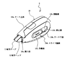
図1は、本発明に係る塗布膜転写具の一実施形態における外観の構成を示す斜視図である。図1に示すように、本実施形態の塗布膜転写具1のケース10(筐体)として機能するケース上部10aとケース下部10bは組立可能に形成されており、その内部には、搬送テープの表面に糊剤等からなる転写層が設けられる転写テープTを巻装して構成されるテープユニット4が内蔵される。前記搬送テープは、転写層を搬送する媒体として機能する。
(Overview of overall configuration)
FIG. 1 is a perspective view showing an external configuration of an embodiment of a coating film transfer tool according to the present invention. As shown in FIG. 1, a case upper part 10a and a case lower part 10b that function as a case 10 (housing) of the coating
本発明に係る塗布膜転写具は、転写テープTを懸架する転写ヘッド5を備えており、使用者が、スライドノブなどで構成される作動部101をケース10の開口部10c方向及びその反対方向に向かってスライドさせることにより、転写ヘッド5をケース10から突出させたり、ケース10の内部に収納させたりすることができる。使い方としては、作動部101を摺動させて、転写ヘッド5で転写テープを懸架し、その懸架させた当接部分を紙面などの被転写面(転写対象)に圧接して移動(転写テープを走行)させることにより、転写面が前記被転写面に転写される。この「転写」動作では、供給ボビン21から転写テープTが引き出されることとなる。
The coating film transfer tool according to the present invention includes a transfer head 5 for suspending a transfer tape T, and the user moves the operation unit 101 configured by a slide knob or the like in the direction of the opening 10c of the
なお、本実施形態の説明では、転写ヘッド5をケース10の開口部10cから外へ突出させる方向を「突出方向」とし、転写ヘッド5をケース10の内側に収納する方向を「収納方向」として説明する。
In the description of the present embodiment, the direction in which the transfer head 5 protrudes from the opening 10c of the
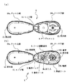
図2は、本実施形態における塗布膜転写具1の分解斜視図である。図2に示すように、塗布膜転写具1は、ケース上部10a及びケース下部10bとからなるケース10に、転写テープTを巻装した供給ボビン21及び転写テープTを巻き取るための巻取ボビン31を内蔵したテープユニット4と、供給ボビン21に係合して回転を伝達させる供給リール2と、巻取ボビン31に係合して回転を伝達させる巻取リール3と、転写ヘッド5と、その転写ヘッド5に連結され、ケース10の内外を摺動動作させると共に、その摺動動作に応じて、テープユニット4に内蔵される供給ボビン21及び巻取ボビン31に対する回転伝達を制御するスライド機構とから構成される。
FIG. 2 is an exploded perspective view of the coating
図3は、本実施形態における塗布膜転写具1を構成するケース上部10a及びケース下部10bの構成を示す図である。図3に示すように、塗布膜転写具1は、矩形をなす開口部10c(図1参照)を、一辺とコの字形状とに分けるようにケース上部10a及びケース下部10bがヒンジ部11で連結されている。また、収納方向におけるヒンジ部11に対向する端部には、ヒンジ部11によって互いに回動可能なケース上部10aとケース下部10bとを係止し、固着させる係合部12,12が設けられている。
FIG. 3 is a view showing the configuration of the case upper part 10a and the case lower part 10b constituting the coating
テープユニット4を着脱する際には、ケース下部10bを固定した状態で、係合部12,12を解除し、ヒンジ部11を軸として、突出方向にケース上部10aを回動させてケース上部10a及びケース下部10bを開いた状態にして行う。一方、テープユニット4をケース下部10bに装着した後は、再びヒンジ部11を軸として、ケース上部10aを収納方向に回動させて重ね合わされたケース上部10aとケース下部10bとを係合部12,12で係止し、固着させる。
When attaching or detaching the
(テープユニットの構成)
図4は、本実施形態におけるテープユニット4の構成を示す側面図であり、図4(a)は、ケース下部10bに対向する側の側面図であり、図4(b)は、ケース上部10aに対向する側の側面図である。なお、テープユニット4は、図4(a)に示す側の面をケース下部10bに対して対向させ、取り付けるものとする。
(Tape unit configuration)
FIG. 4 is a side view showing the configuration of the
テープユニット4は、図4に示すように、転写テープTを巻装した供給ボビン21、及びその供給ボビン21から引き出されて使用された使用済み転写テープTを巻着するための巻取ボビン31を並列に配設し、2枚の樹脂プレート40で挟んだ態様をなしている。そのため、転写テープTを全て使い終わった際に、このテープユニット4を取り外して新しいものと交換することが可能であり、転写テープTの交換作業が容易となっている。
As shown in FIG. 4, the
供給ボビン21及び巻取ボビン31は、共に樹脂成型して円筒状に形成される。また、転写テープTとしては、ポリエステルフィルム等の樹脂テープからなる搬送テープの表面に糊剤から成る転写層を搬送テープ表面から剥離可能に設けたものが使用されている。なお、搬送テープには紙テープを使用することも可能である。 Both the supply bobbin 21 and the take-up bobbin 31 are formed into a cylindrical shape by resin molding. In addition, as the transfer tape T, a transfer tape made of a paste is provided on the surface of a transport tape made of a resin tape such as a polyester film so as to be peelable from the surface of the transport tape. It is also possible to use a paper tape as the transport tape.
また、テープユニット4には、供給ボビン21から引き出された転写テープTを巻取ボビン31へ至らせる前に張架させる張架部材41が形成されており、この張架部材41は、テープユニット4をケース10に収納した際に、ケース10内に収納状態となっている転写ヘッド5とケース10の開口部10cとの間に転写テープTが張架されるように構成される。例えば、ケース10に収納した際に開口部10cが位置する方向に突出し、供給ボビン21及び巻取ボビン31の回転軸に直交する方向(転写テープTが走行する方向)に対をなす1対の張架部材41として構成される。
Further, the
なお、本実施形態において、ケース下部10bに装着される側からみて、転写テープTは、供給ボビン21に対して右巻きで巻装されており、巻取ボビン31に対しては左巻きで巻装されている。従って、本実施形態の説明中、転写時の動作(供給ボビン21から転写テープTが供給される動作)において、供給ボビン21及び供給リール2、又は巻取ボビン31及び巻取リール3が回転する方向(右回り)を「正回転(方向)」と表現し、その反対方向に供給ボビン21(供給リール2)又は巻取リール3が回転する場合には「逆回転(方向)」と表現する。 In the present embodiment, when viewed from the side to be attached to the bottom case 10b, the transfer tape T is wound in a right-handed with respect to the supply bobbin 21, winding the left winding for the winding bobbin 31 It is disguised. Accordingly, during the description of the present embodiment, the supply bobbin 21 and the supply reel 2 or the take-up bobbin 31 and the take-up reel 3 rotate during the transfer operation (operation in which the transfer tape T is supplied from the supply bobbin 21). The direction (clockwise) is expressed as “forward rotation (direction)”, and when the supply bobbin 21 (supply reel 2) or the take-up reel 3 rotates in the opposite direction, it is expressed as “reverse rotation (direction)”. .
また、本実施形態におけるテープユニット4では、巻取ボビン31は逆回転しないように構成されているものとする。
Moreover, in the
(供給リールの構成)
供給リール2も樹脂成型して形成されており、その周縁に形成された歯車2aと、テープユニット4に内蔵される供給ボビン21に対して係合するスリップ機構付きクラッチ22とを有する。
(Composition of supply reel)
The supply reel 2 is also formed by resin molding, and has a gear 2 a formed on the periphery thereof, and a clutch 22 with a slip mechanism that engages with a supply bobbin 21 built in the
供給リール2は、ケース下部10bに立設される軸部10dに緩挿されて回転自在に取り付けられている。供給リール2の周縁に形成された歯車2aは、リール連動歯車6と噛合されている。このリール連動歯車6が、本請求項にいうリール連動手段である。
The supply reel 2 is loosely inserted into a shaft portion 10d erected on the case lower portion 10b and is rotatably attached. A gear 2 a formed on the peripheral edge of the supply reel 2 is meshed with the
また、供給リール2のケース下部10b側の面には、歯車2aよりも小さな径の歯車2bが形成されており、後述する歯車103と噛合可能とされている。 A gear 2b having a diameter smaller than that of the gear 2a is formed on the surface of the supply reel 2 on the case lower part 10b side, and can be engaged with a gear 103 described later.
(リール連動歯車の構成)
リール連動歯車6は、ケース下部10bに立設される軸部10eに緩挿されて回転自在に取り付けられており、供給リール2の歯車2a及び巻取リール3の歯車3aと噛合されている。この歯車6を設けることにより、供給リール2と巻取リール3とが連動され、同方向に回転可能とされる。
(Configuration of reel interlocking gear)
The
なお、本実施形態において、「連動」とは、供給リール2及び巻取リール3と、これらに噛合しているリール連動歯車6との動作関係のように、一方の回転が他方の回転にそのまま伝達されることを指す。従って、転写動作における巻取ボビン31と巻取リール3とは正回転方向に「連動」しているが、転写ヘッド5を突出させる動作を行った場合には、前述したスリップ機構により、意図的に供給ボビン21の回転と供給リール2の回転とが異なるようにしたため、供給ボビン21の回転がそのまま供給リール2に伝達されず、「連動」が解除された状態といえる。
In the present embodiment, “interlocking” means that one rotation is directly changed to the other rotation as in the operation relationship between the supply reel 2 and the take-up reel 3 and the
(巻取リールの構成)
図5は、本実施形態において巻取リール3と巻取ボビン31との連動によって構成される巻取機構の構成を示す図であって、図5(a)はケース下部10bに対向する側の巻取リール3の斜視図、図5(b)はケース上部10aに対向する側の巻取リール3の斜視図、図5(c)は、巻取リール3に係合される巻取ボビン31を備えたテープユニットの斜視図である。
(Configuration of take-up reel)
FIG. 5 is a diagram showing a configuration of a winding mechanism configured by interlocking the winding reel 3 and the winding bobbin 31 in the present embodiment, and FIG. 5A is a side of the case facing the case lower part 10b. FIG. 5B is a perspective view of the take-up reel 3 on the side facing the case upper portion 10 a, and FIG. 5C is a take-up bobbin 31 engaged with the take-up reel 3. It is a perspective view of a tape unit provided with.
巻取リール3は、ケース下部10bに立設される軸部10fに緩挿されて回転自在に取り付けられており、図5(a)に示す巻取リール3の周縁部に設けられる歯車3aがリール連動歯車6と噛合されている。
The take-up reel 3 is loosely inserted into a
また、図5(b)に示すように、巻取リール3の内周には、ケース上部10aに向かって先端部分が起立した係合爪3bが形成される。 Further, as shown in FIG. 5B, an engaging claw 3b is formed on the inner periphery of the take-up reel 3 with its tip portion standing up toward the case upper portion 10a.
さらに、図5(c)に示すように、巻取ボビン31の内縁部には、当該巻取ボビン31が正回転するときに係合爪3bに係合し、巻取リール3が逆回転するときには、係合爪3bが係合されずに空転する形状に形成された係止リブ31aが設けられる。 Further, as shown in FIG. 5C, the inner edge of the take-up bobbin 31 is engaged with the engaging claw 3b when the take-up bobbin 31 rotates forward, and the take-up reel 3 rotates reversely. In some cases, a locking rib 31a is provided that is formed in a shape that idles without being engaged with the engaging claw 3b.
従って、ケース10にテープユニット4を装着した際、巻取リール3に巻取ボビン31が装着され、初期状態としては、係止リブ31aと係合爪3bとが係合した状態に置かれる。
Therefore, when the
そして、巻取ボビン31又は巻取リール3が正回転するときには、巻取リール3と巻取ボビン31が連動して正回転方向に回転し、巻取リール3が逆回転するときには、巻取ボビン31は停止したまま、巻取リール3だけが逆回転することとなる。 When the take-up bobbin 31 or the take-up reel 3 rotates in the forward direction, the take-up reel 3 and the take-up bobbin 31 rotate in the forward rotation direction in conjunction with each other, and when the take-up reel 3 rotates in the reverse direction, the take-up bobbin. While 31 is stopped, only the take-up reel 3 rotates in the reverse direction.
なお、本実施形態においては、巻取リール3に装着される巻取ボビン31に使用済み転写テープTを巻着する構成を示したが、本発明はこれに限定されるものではなく、巻取リール3に直接転写テープTを巻着する構成とすることも可能である。 In the present embodiment, the configuration in which the used transfer tape T is wound around the winding bobbin 31 attached to the winding reel 3 is shown, but the present invention is not limited to this, and the winding is not limited to this. A configuration in which the transfer tape T is directly wound around the reel 3 is also possible.
(スリップ機構の構成)
スリップ機構(スリップ機構付きクラッチ22)は、供給リール2においてテープユニット4に対向する面側に形成された収納突起22aに、供給ボビン21に対して係合する軸部22bが収納されてなる。
(Slip mechanism configuration)
The slip mechanism (clutch 22 with slip mechanism) is configured such that a shaft protrusion 22 b that engages with the supply bobbin 21 is stored in a storage protrusion 22 a formed on the surface side of the supply reel 2 that faces the
収納突起22a内に軸部22bを収納した供給リール2は、軸部22b及び供給リール2に共通の嵌合孔(図示せず)をケース下部10bに立設される軸部10dに嵌挿させて軸部10dに回転可能に軸支される。 The supply reel 2 in which the shaft portion 22b is stored in the storage protrusion 22a has a fitting hole (not shown) common to the shaft portion 22b and the supply reel 2 fitted into the shaft portion 10d erected on the case lower portion 10b. And is rotatably supported by the shaft portion 10d.
そして、供給ボビン21の回転がこのスリップ機構(スリップ機構付きクラッチ22)を介して供給リール2に伝達可能となっている。 The rotation of the supply bobbin 21 can be transmitted to the supply reel 2 via this slip mechanism (clutch 22 with a slip mechanism).
このようにして、本実施形態のスリップ機構(スリップ機構付きクラッチ22)は、収納突起22a及び軸部22bによる摩擦クラッチとして、供給ボビン21から引き出される転写テープTの引き出し量と巻取ボビン31に巻着される使用済み転写テープTの巻取り量を等しくすると共に、転写テープTの緊張を一定に保つ働きをしている。 In this manner, the slip mechanism (clutch 22 with slip mechanism) of the present embodiment serves as a friction clutch by the storage protrusion 22a and the shaft portion 22b, and the pulling amount of the transfer tape T drawn from the supply bobbin 21 and the take-up bobbin 31. The winding amount of the used transfer tape T to be wound is made equal, and the tension of the transfer tape T is kept constant.
また、本実施形態のスリップ機構(スリップ機構付きクラッチ22)は、後述する転写ヘッド5のスライド動作や転写動作に伴って、供給ボビン21から転写テープTが引き出されたときに機能するものである。 Further, the slip mechanism (clutch 22 with slip mechanism) of the present embodiment functions when the transfer tape T is pulled out from the supply bobbin 21 in accordance with a slide operation or transfer operation of the transfer head 5 described later. .
具体的には、転写ヘッド5を突出させる動作を行ったときには、転写テープTが転写ヘッド5に引っ張られることによって、供給ボビン21及び/又は巻取ボビン31から転写テープTが引き出されなければならなくなる。ここで、巻取ボビン31は、正回転方向にしか回転しないので回転せず、それに伴って巻取リール3、リール連動歯車6及び供給リール2も回転しないので、供給ボビン21から転写テープTが引き出されるために、供給リール2に対して供給ボビン21が正回転方向に滑って回転する機構である。
Specifically, when the operation of projecting the transfer head 5 is performed, the transfer tape T must be pulled out from the supply bobbin 21 and / or the take-up bobbin 31 by the transfer tape T being pulled by the transfer head 5. Disappear. Here, since the take-up bobbin 31 rotates only in the forward rotation direction, it does not rotate, and accordingly, the take-up reel 3, the
また、転写操作のときには、巻取ボビン31に巻着される使用済み転写テープTの巻取り量が転写テープTの引き出し量を超過するように機能することにより、転写テープTの弛みが防止されており、転写テープTの緊張が必要以上に高まる前に、収納突起22aに対して軸部22bが滑動して転写テープTの張力を下げることにより、転写テープTの切断が防止されると共に転写テープの緊張が略一定に保たれている。 Further, during the transfer operation, the transfer tape T is prevented from slacking by functioning so that the winding amount of the used transfer tape T wound around the winding bobbin 31 exceeds the pull-out amount of the transfer tape T. Then, before the tension of the transfer tape T is increased more than necessary, the shaft portion 22b slides with respect to the storage protrusion 22a to reduce the tension of the transfer tape T, thereby preventing the transfer tape T from being cut and transferring. The tension of the tape is kept almost constant.
ここで、本実施形態のスリップ機構としてスリップ機構付きクラッチ22を構成する軸部22bの形状は、供給ボビン21が正回転したときに、大きなトルク(収納突起22aに対して滑りにくい)でその回転を供給リール2に伝達し、供給リール2が逆回転したときには、小さなトルク(収納突起22aに対して滑りやすい)でその回転を供給ボビン21に伝達する構造とされている。 Here, the shape of the shaft portion 22b that constitutes the clutch 22 with the slip mechanism as the slip mechanism of the present embodiment is such that when the supply bobbin 21 rotates in the forward direction, it rotates with a large torque (not slippery with respect to the storage protrusion 22a). Is transmitted to the supply reel 2, and when the supply reel 2 rotates in the reverse direction, the rotation is transmitted to the supply bobbin 21 with a small torque (sliding easily with respect to the storage protrusion 22 a).
(転写ヘッドの構成)
転写ヘッド5は、供給リール2及び巻取リール3と同じ回転軸をなすローラー51を前方に備え、このローラー51が供給ボビン21から引き出され、巻取ボビン31に巻着される転写テープTをその途中で懸架し、使用時には回転して転写テープTの走行を滑らかなものにする役割をなす。
(Configuration of transfer head)
The transfer head 5 includes a
(スライド機構の構成)
本発明の特徴部分であるスライド機構100は、ケース下部10bの内面に対して摺動するように設置されて、先端部に転写ヘッド5を固定した連結部102を中心に構成されている。そして、転写ヘッド5をケース10の開口部10cから突出及び収納させる連結部102と、その連結部102を使用者が操作するために、ケース下部10bを介してその外面に形成された摺動溝10h(図1参照)に沿って摺動するように設置された作動部101と、転写ヘッド5が使用状態からケース10内に収納されるときに連結部102の伝達部102bのラック状ギア構造に噛み合って、摺動変位に応じて供給リール2を回転させる歯車103と、作動部101を操作して(スライドさせて)ケース10の開口部10cから転写ヘッド5を突出させて、塗布膜転写具1を使用状態としたときに転写ヘッド5を固定すると共に、作動部101を操作して(スライドさせて)使用状態とされた転写ヘッド5をケース10の内部に収納する動作を補助するバネ部104とを有してなる。
(Configuration of slide mechanism)
The slide mechanism 100, which is a characteristic part of the present invention, is configured so as to slide with respect to the inner surface of the case lower part 10b, and is configured around a connecting part 102 in which the transfer head 5 is fixed to the tip part. Then, a connecting portion 102 for projecting and storing the transfer head 5 from the opening 10c of the
連結部102は、中央部分に貫通孔102aが形成された平板形状をなし、突出方向の端部に転写ヘッド5が設置されている。連結部102は、前述した軸部10d及び軸部10eが貫通孔102aに嵌挿されるように設置されており、結果として連結部102は、ケース下部10bと供給リール2及び巻取リール3とに挟まれるようにして「突出方向」及び「収納方向」に摺動することとなる。
The connecting portion 102 has a flat plate shape in which a through hole 102a is formed in the central portion, and the transfer head 5 is installed at an end portion in the protruding direction. The connecting portion 102 is installed so that the shaft portion 10d and the
また、連結部102の貫通孔102aの内縁部には、鋸歯形状の伝達部102bが形成されており、貫通孔102aを通してケース下部10bに形成された長円形状の凹部10gに遊嵌された歯車103が伝達部102bに噛合されている。この歯車103は、凹部10gが「突出方向」及び「収納方向」に長径を有する長円形状をなすことにより、「突出方向」及び「収納方向」に摺動可能となっている。 Further, a serrated transmission portion 102b is formed at the inner edge portion of the through hole 102a of the connecting portion 102, and a gear that is loosely fitted into an oval concave portion 10g formed in the case lower portion 10b through the through hole 102a. 103 is engaged with the transmission portion 102b. The gear 103 is slidable in the “protruding direction” and the “accommodating direction” by forming the recess 10 g into an oval shape having a long diameter in the “projecting direction” and the “accommodating direction”.
図6(a)に示すように、バネ部104は、ケース下部10bに形成された摺動溝10h(図1参照)に収納されて、ケース下部10bを介して連結部102に接続されている。また、バネ部104は、摺動溝10hの側壁部に形成された係止溝10iに係合する係合片104aが収納方向に開形状で2つ設けられている。 As shown in FIG. 6A, the spring portion 104 is housed in a sliding groove 10h (see FIG. 1) formed in the case lower portion 10b, and is connected to the connecting portion 102 via the case lower portion 10b. . Moreover, the spring part 104 is provided with two engagement pieces 104a that are engaged with a locking groove 10i formed on the side wall of the sliding groove 10h in an open shape in the storage direction.
係合片104aにはそれぞれ、作動部101が設置される面側に突起部104bが設けられている。 Each of the engagement pieces 104a is provided with a protrusion 104b on the surface side where the operation unit 101 is installed.
図6(b)に示すように、作動部101には、係合片104a(バネ部104)に対向する面に係合溝101aが形成され、この係合溝101aに突起部104bが嵌合している。
As shown in FIG. 6B, the operating portion 101 is formed with an engaging
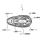
次に、本発明に係る塗布膜転写具の一実施形態における動作について、図面を参照して以下に説明する。図7〜図11は、本実施形態における動作を説明するための図であり、図7は、本実施形態における転写ヘッド収納時の塗布膜転写具の透過斜視図、図8は、本実施形態における転写ヘッド収納時の塗布膜転写具の透過側面図、図9は、本実施形態における転写ヘッド突出時の塗布膜転写具の透過斜視図、図10は、本実施形態における転写ヘッド突出時の塗布膜転写具の透過側面図、図11は、本実施形態におけるスライド機構の一部をなす固定機構の動作を示す側面図である。 Next, the operation in one embodiment of the coating film transfer tool according to the present invention will be described below with reference to the drawings. 7 to 11 are diagrams for explaining the operation in this embodiment. FIG. 7 is a transparent perspective view of the coating film transfer tool when the transfer head is housed in this embodiment. FIG. 8 is this embodiment. 9 is a transparent side view of the coating film transfer tool when the transfer head is housed in FIG. 9, FIG. 9 is a transparent perspective view of the coating film transfer tool when the transfer head projects in the present embodiment, and FIG. 10 is a diagram when the transfer head projects in the present embodiment. FIG. 11 is a side view showing the operation of the fixing mechanism forming a part of the slide mechanism in the present embodiment.
図7及び図8に示すように、転写ヘッド5をケース10内に収納した状態の塗布膜転写具1では、作動部101が摺動溝10hの収納方向端部近傍にあって、供給ボビン21が装着された供給リール2と、巻取ボビン31が装着された巻取リール3と、供給リール2の回転を巻取リール3に伝達するリール連動歯車6とが静止状態である。
As shown in FIGS. 7 and 8, in the coating
また、供給ボビン21から引き出された転写テープTは、テープユニット4における突出方向端部に形成された張架部材41,41に張架されて巻取ボビン31に巻装されている。張架部材41,41で張架された転写テープTは、開口部10cの内側を覆うように位置される。
Further, the transfer tape T pulled out from the supply bobbin 21 is stretched around
ここで、使用者によって作動部101が摺動溝10hに沿って突出方向に摺動されたとき、図9及び図10に示すように、連結部102を介して作動部101に連結された転写ヘッドは、張架部材41,41に挟まれた態様でケース10の外部に突出する。
Here, when the operating part 101 is slid in the protruding direction along the sliding groove 10h by the user, the transfer connected to the operating part 101 via the connecting part 102 as shown in FIGS. The head protrudes to the outside of the
従って、張架部材41,41によって張架された転写テープTを、ローラー51(図2参照)に懸架させた状態で転写ヘッド5はケース10の外部に突出することになる。
Accordingly, the transfer head 5 protrudes outside the
このとき、ケース10の内部では、巻取ボビン31が逆回転しない構造となっているため、上述した係止リブ31a及び係合爪3bが係合したまま巻取リール3に回転が伝達されず、リール連動歯車6及び供給リール2も固定されるので、転写ヘッド5のローラー51に懸架された転写テープTは、スリップ機構により供給リール2に対して滑りながら正回転する供給ボビン21から転写ヘッド5が突出した移動変位に応じた長さだけ引き出されることとなる。
At this time, since the winding bobbin 31 does not reversely rotate inside the
なお、この転写ヘッド5の突出動作では、巻取ボビン31が逆回転しないので、リール連動歯車6を介した供給リール2も逆回転しない。
In this projecting operation of the transfer head 5, the take-up bobbin 31 does not rotate reversely, so the supply reel 2 via the
従って、供給リール2と供給ボビン21とを連結しているスリップ機構付きクラッチ22は、供給ボビン21に係合している軸部22bが収納突起22aに対して滑りながら回転することになる。 Accordingly, the clutch 22 with the slip mechanism connecting the supply reel 2 and the supply bobbin 21 rotates while the shaft portion 22b engaged with the supply bobbin 21 slides with respect to the storage protrusion 22a.
ケース10の外部に突出させた転写ヘッド5は、使用状態となり、ケース10の内部に不意に収納されないように固定される。この固定機構について図11(a)〜(c)を参照して以下に説明する。
The transfer head 5 protruding outside the
前述したように、転写ヘッド5は、連結部102を介してバネ部104及び作動部101に接続されている。従って、ケース下部10bに形成された摺動溝10hと、この摺動溝10h内を摺動するバネ部104と、このバネ部104を制御する作動部101によって前記固定機構が構成されている。 As described above, the transfer head 5 is connected to the spring portion 104 and the operating portion 101 via the connecting portion 102. Therefore, the fixing mechanism is constituted by the sliding groove 10h formed in the case lower part 10b, the spring part 104 sliding in the sliding groove 10h, and the operating part 101 for controlling the spring part 104.
図11(a)〜(f)は、本実施形態におけるスライド機構の一部である固定機構の動作を示す図であり、当該図は、ケース下部10bに形成された摺動溝10h及びその摺動溝10hの側面部に形成された係止溝10iに対する作動部101及びバネ部104の動作を示したものである。 FIGS. 11A to 11F are views showing the operation of a fixing mechanism which is a part of the sliding mechanism in the present embodiment, and this figure shows the sliding groove 10h formed in the case lower part 10b and its sliding. The operation | movement of the action | operation part 101 and the spring part 104 with respect to the locking groove 10i formed in the side part of the dynamic groove 10h is shown.
図11(a)に示すように、摺動溝10hに収納されたバネ部104の係合片104a,104aは、転写ヘッド5が本体10の内部に収納されている状態では、収納方向側の1対の係止溝10iにそれぞれ係合されている。
As shown in FIG. 11A, the engaging pieces 104a and 104a of the spring portion 104 housed in the sliding groove 10h are located on the housing direction side when the transfer head 5 is housed inside the
使用者が作動部101を突出方向に摺動させたとき、図11(b)に示すように、係合片104a,104aは収納方向に開形状(収納方向に開いた「ハ」の字形状)をなしているので、各係合片104a,104aはスムーズに係止溝10iから離脱する。 When the user slides the operating portion 101 in the protruding direction, as shown in FIG. 11 (b), the engagement pieces 104a and 104a are open in the storage direction ("C" shape open in the storage direction). ), The engaging pieces 104a and 104a are smoothly detached from the locking groove 10i.
そして、作動部101を突出方向に摺動させて、転写ヘッド5が完全にケース10の外部に突出したとき、図11(c)に示すように、各係合片104a,104aは突出方向側の1対の係止溝10iにそれぞれ係合されることになる。
When the operation unit 101 is slid in the protruding direction and the transfer head 5 is completely protruded outside the
前述したように、係合片104a,104aは収納方向に開形状をなしているので、各係合片104a,104aは突出方向側の1対の係止溝10iから離脱しにくい状態となり、バネ部104は収納方向に対して固定された状態となる結果、連結部102を介して転写ヘッド5も固定されることとなる。 As described above, since the engagement pieces 104a and 104a are open in the storage direction, the engagement pieces 104a and 104a are not easily detached from the pair of locking grooves 10i on the protruding direction side, and the springs As a result of the portion 104 being fixed in the storage direction, the transfer head 5 is also fixed via the connecting portion 102.
転写ヘッド5を本体10から突出させた状態で、塗布膜転写具1は使用状態となる。この使用時では、転写対象に対してケース下部10bを左側にして、転写テープTが懸架された転写ヘッド5を転写対象に押しつけ、手前に引くようにする(転写テープTを走行させる)ことで供給ボビン21が正回転し、その回転がスリップ機構付きクラッチ22及び供給リール2を介してリール連動歯車6に伝わり、巻取リール3を経て巻取ボビン31が正回転することによって使用済みの転写テープTを巻装することとなる。
With the transfer head 5 protruding from the
このときも、スリップ機構付きクラッチ22によって、供給ボビン21から引き出される転写テープTの量と巻取ボビン31に巻着される転写テープTの量とがほぼ同量に保たれると共に、転写テープTの緊張度合いが一定に維持されている。 Also at this time, the amount of the transfer tape T pulled out from the supply bobbin 21 and the amount of the transfer tape T wound around the take-up bobbin 31 are kept substantially equal by the clutch 22 with a slip mechanism, and the transfer tape. The degree of T tension is kept constant.
その後、塗布膜転写具1の使用が終了し、転写ヘッド5を再びケース10の内部に収納する際には、使用者が作用部101を収納方向に摺動させることによって、作用部101に接続されたバネ部104及び連結部102を介して転写ヘッド5がケース10の内部に収納されることとなるが、このとき、本発明のスライド機構は、転写ヘッド5のケース10内部への収納と同時に転写テープTの適正な収納も実現させる。
Thereafter, when the use of the coating
具体的には、まず、前述した転写ヘッド5の突出動作では、連結部102が突出方向に摺動するのに伴って、伝達部102bに噛合された歯車103が供給リール2の歯車2bから離されて、歯車2bとの噛合が解除された状態とされている。これは、凹部10gが突出方向及び収納方向に長径を有する長円形状をなしていることで歯車103が突出方向に移動することに起因する。 Specifically, first, in the protrusion operation of the transfer head 5 described above, the gear 103 engaged with the transmission portion 102b is separated from the gear 2b of the supply reel 2 as the connecting portion 102 slides in the protrusion direction. Thus, the meshing with the gear 2b is released. This is because the gear 103 moves in the protruding direction because the concave portion 10g has an oval shape having a long diameter in the protruding direction and the storing direction.
従って、転写ヘッド5の収納動作を行った場合、それに伴う連結部102の収納方向への摺動によって、歯車103が凹部10gの長軸方向に沿って収納方向に摺動し、歯車2bと噛合する。 Accordingly, when the storing operation of the transfer head 5 is performed, the gear 103 slides in the storing direction along the major axis direction of the recess 10g due to the sliding of the connecting portion 102 in the storing direction, and meshes with the gear 2b. To do.
そして、転写ヘッド5の収納動作が続行され、連結部102の収納方向への摺動によって、歯車103は伝達部(ラック状ギア)102bに噛合して正回転し、この歯車103に噛合した供給リール2の歯車2bが逆回転する。そうすると、リール連動歯車6を介して巻取リール3も逆回転する。ここで、逆回転時には係止リブ31aに対して、係合爪3bは係止されない形状としているので、巻取リール3が逆回転しても、その回転は巻取ボビン31には伝達されない。
Then, the storing operation of the transfer head 5 is continued, and the gear 103 is meshed with the transmission unit (rack-shaped gear) 102b by the sliding of the connecting unit 102 in the storing direction, so that the supply is meshed with the gear 103. The gear 2b of the reel 2 rotates in the reverse direction. Then, the take-up reel 3 also rotates in reverse via the
よって、転写ヘッド5の収納動作に連動して、連結部102に形成された伝達部102b及び歯車103を介して供給リール2が逆回転し、供給ボビン21により、転写ヘッド5の突出動作で引き出された転写テープTを巻取って、張架部材41,41で張架された転写テープTを、開口部10cの内側を覆うように初期の位置(図7参照)に戻すことができる。
Accordingly, in conjunction with the storing operation of the transfer head 5, the supply reel 2 rotates reversely via the transmission portion 102 b and the gear 103 formed in the connecting portion 102, and is pulled out by the supply bobbin 21 by the protruding operation of the transfer head 5. The transferred transfer tape T is wound up, and the transfer tape T stretched by the stretching
なお、凹部10gの長径の長さは、歯車2bとの噛合を解除でき、かつ転写ヘッド5の収納動作を行った場合に可及的速やかに歯車2bと噛合することができる程度に設計される。 Note that the length of the major axis of the recess 10g is designed such that the engagement with the gear 2b can be released and the engagement with the gear 2b can be performed as quickly as possible when the storing operation of the transfer head 5 is performed. .
このときも、スリップ機構付きクラッチ22によって、転写テープTの緊張度合いが一定に維持されている。なお、一方側が固定された(回転しない)巻取ボビン31によって引っ張られた転写テープTの他方側を供給ボビン21の逆回転動作によって引っ張りすぎたとしても、前述したように、軸部22bの形状は、装着された供給リール2が逆回転しているときには収納突起22aに対して滑りやすい形状となっているので、転写テープTの張力がある程度以上になっても、供給リール2に対して供給ボビン21が滑るので、転写テープTが過剰に引っ張られ、破損することはない。 Also at this time, the tension of the transfer tape T is kept constant by the clutch 22 with the slip mechanism. Even if the other side of the transfer tape T pulled by the take-up bobbin 31 fixed on one side (not rotated) is pulled too much by the reverse rotation operation of the supply bobbin 21, as described above, the shape of the shaft portion 22b Has a shape that is slippery with respect to the storage protrusion 22a when the mounted supply reel 2 is rotating in the reverse direction, so that even if the tension of the transfer tape T exceeds a certain level, the supply reel 2 is supplied. Since the bobbin 21 slips, the transfer tape T is pulled excessively and is not damaged.
次に、転写ヘッド5の収納動作における前記固定機構の動作について、図11(c)〜(f)を参照して以下に説明する。 Next, the operation of the fixing mechanism in the storing operation of the transfer head 5 will be described below with reference to FIGS.
転写ヘッド5がケース10の外部に突出しているときは、図11(c)に示すように、各係合片104a,104aは突出方向側の1対の係止溝10iにそれぞれ係合されている。
When the transfer head 5 protrudes outside the
ここで、転写ヘッド5の収納動作を開始することは、作動部101を収納方向に摺動することを意味する。また、係合片104a,104aに設けられた突起部104bは作動部101の係合溝101aに係合しており、それら係合溝101aの形状は、収納方向に開形状(収納方向に開いた「ハ」の字形状)をなしている。
Here, starting the storing operation of the transfer head 5 means sliding the operation unit 101 in the storing direction. Further, the engaging pieces 104a, the protrusion 104b provided on 104a is engaged with the engaging
すなわち、転写ヘッド5の収納動作を開始すると、突起部104bは作動部101の係合溝101aの形状に沿って、係合片104a,104aを互いに近づけさせるように働き、係合片104a,104aは突出方向側の1対の係止溝10iから離脱し、転写ヘッド5の固定が解除されることとなる。
That is, when starting the storing operation of the transfer head 5, the projection portion 104b along the shape of the engaging
そして、引き続き作動部101を収納方向に摺動させると、図11(e)に示すように、係合片104a,104aは摺動溝10hの側面に沿って摺動し、転写ヘッド5が完全にケース10の内部に収納されたとき、図11(f)に示すように、各係合片104a,104aは再び、収納方向側の1対の係止溝10iにそれぞれ係合されることになる。 When the operating portion 101 is continuously slid in the storage direction, the engaging pieces 104a and 104a slide along the side surfaces of the sliding groove 10h as shown in FIG. 11 (f), the engaging pieces 104a and 104a are again engaged with the pair of locking grooves 10i on the storing direction side, respectively. Become.
以上説明したように、本発明によれば、スライド機構を設けたので、未使用時に転写テープを保護しつつ、使用時にたるみが生じないように構成した塗布膜転写具を提供することができる。 As described above, according to the present invention, since the slide mechanism is provided, it is possible to provide a coating film transfer tool configured to protect the transfer tape when not in use and prevent slack during use.
また、スライド機構に加え、供給リールにスリップ機構を備えたので、転写ヘッドの突出動作/収納動作を繰り返しても転写テープのたるみを解消し、常に適正な使用準備状態とすることができる。 In addition to a slide mechanism, so with a slip mechanism to the supply reel can be repeat protruding operation / storage operation of the transfer head to eliminate the slack of the transfer tape is always proper use ready .
1 塗布膜転写具
10 ケース
10a ケース上部
10b ケース下部
10c 開口部
10d 軸部
10e 軸部
10f 軸部
10g 凹部
10h 摺動溝
10i 係止溝
11 ヒンジ部
12 係合部
2 供給リール
21 供給ボビン
2a 歯車
2b 歯車
22 スリップ機構付きクラッチ
22a 収納突起
22b 軸部
3 巻取リール
3a 歯車
3b 係合爪
31 巻取ボビン
31a 係止リブ
4 テープユニット
4a テープユニット上部
4b テープユニット下部
41 張架部材
5 転写ヘッド
51 ローラー
6 リール連動歯車
101 作動部(スライドノブ)
101a 係合溝
102 連結部
102a 貫通孔
102b 伝達部
103 歯車
104 バネ部
104a 係合片
104b 突起部
T 転写テープ
DESCRIPTION OF
101a engaging groove 102 connecting portion 102a through hole 102b transmitting portion 103 gear 104 spring portion 104a engaging piece 104b projecting portion T transfer tape
Claims (5)
その供給ボビンを装着し、回転可能な供給リールと、
前記供給ボビンから引き出されて使用された転写テープが巻着され、転写テープを巻き取る方向にだけ回転可能な巻取ボビンと、
転写テープを巻き取る方向に対して前記巻取ボビンと連動して回転する巻取リールと、
前記供給リールと前記巻取リールとを連動させるリール連動手段と、
転写テープを被転写面に圧接させて当該転写テープを走行させることにより塗布膜の転写を行うための転写ヘッドと、がケースに含まれた塗布膜転写具であって、
前記転写ヘッドを摺動させて、前記転写を行うために前記転写テープに当接させて前記ケースから突出させ、さらに、前記ケース内に収納させるスライド機構と、
前記供給ボビンと前記供給リールとの間に介在し、前記転写ヘッドを突出させる摺動動作が前記スライド機構により行われたとき、前記供給ボビンと前記供給リールとの連動を解除し、前記転写時における前記転写テープの走行により、転写テープを供給する方向に前記供給ボビンが回転するときは、その方向に前記供給リールと前記供給ボビンとを連動して回転させるスリップ機構とを備え、
さらに、前記スライド機構は、前記転写ヘッドを収納する摺動動作をさせたとき、前記供給リールに係合して当該供給リールを逆回転させることを特徴とする塗布膜転写具。 A transfer bobbin around which a transfer tape is wound and rotatable;
The supply bobbin is mounted and a rotatable supply reel,
A take-up bobbin that is wound around the transfer tape drawn out from the supply bobbin and is rotatable only in the direction of winding the transfer tape;
A take-up reel that rotates in conjunction with the take-up bobbin with respect to the winding direction of the transfer tape;
Reel interlocking means for interlocking the supply reel and the take-up reel;
A transfer head for transferring the coating film by causing the transfer tape to contact the surface to be transferred and running the transfer tape, and a coating film transfer tool included in the case,
A slide mechanism that slides the transfer head, abuts against the transfer tape to perform the transfer, protrudes from the case, and is housed in the case;
When the sliding mechanism is interposed between the supply bobbin and the supply reel and causes the transfer head to protrude, the linkage between the supply bobbin and the supply reel is released and the transfer is performed. A slip mechanism for rotating the supply reel and the supply bobbin in conjunction with the supply bobbin when the transfer bobbin rotates in the direction in which the transfer tape is supplied by running the transfer tape in
Furthermore, the slide mechanism engages with the supply reel and rotates the supply reel in reverse when the slide mechanism is slid to house the transfer head.
前記スライド機構は、前記張架部材によって張架された転写テープを前記転写ヘッドで懸架させて前記ケース外に突出させることを特徴とする請求項1に記載の塗布膜転写具。 A tension member is provided to stretch the transfer tape drawn from the supply bobbin and reach the take-up reel,
2. The coating film transfer tool according to claim 1, wherein the slide mechanism causes the transfer tape stretched by the stretch member to be suspended by the transfer head and to protrude out of the case. 3.
Priority Applications (9)
| Application Number | Priority Date | Filing Date | Title |
|---|---|---|---|
| JP2005336173A JP4652955B2 (en) | 2005-11-21 | 2005-11-21 | Coating film transfer tool |
| TW095106743A TWI354628B (en) | 2005-11-21 | 2006-03-01 | Coating film transfer tool |
| SG200601409-6A SG132565A1 (en) | 2005-11-21 | 2006-03-03 | Coating film transfer tool |
| KR1020060022588A KR101196952B1 (en) | 2005-11-21 | 2006-03-10 | Coating film transfer tool |
| CNB2006100570496A CN100522776C (en) | 2005-11-21 | 2006-03-13 | No title available |
| US11/375,208 US7571754B2 (en) | 2005-11-21 | 2006-03-15 | Coating film transfer tool |
| DE102006011929.0A DE102006011929B4 (en) | 2005-11-21 | 2006-03-15 | Transfer device for cover layer |
| FR0606250A FR2893604A1 (en) | 2005-11-21 | 2006-07-10 | TOOL FOR TRANSFERRING COATED FILM |
| HK07108284.1A HK1100434A1 (en) | 2005-11-21 | 2007-07-30 | Coating film transfer tool |
Applications Claiming Priority (1)
| Application Number | Priority Date | Filing Date | Title |
|---|---|---|---|
| JP2005336173A JP4652955B2 (en) | 2005-11-21 | 2005-11-21 | Coating film transfer tool |
Publications (3)
| Publication Number | Publication Date |
|---|---|
| JP2007136959A JP2007136959A (en) | 2007-06-07 |
| JP2007136959A5 JP2007136959A5 (en) | 2009-01-15 |
| JP4652955B2 true JP4652955B2 (en) | 2011-03-16 |
Family
ID=37989625
Family Applications (1)
| Application Number | Title | Priority Date | Filing Date |
|---|---|---|---|
| JP2005336173A Active JP4652955B2 (en) | 2005-11-21 | 2005-11-21 | Coating film transfer tool |
Country Status (9)
| Country | Link |
|---|---|
| US (1) | US7571754B2 (en) |
| JP (1) | JP4652955B2 (en) |
| KR (1) | KR101196952B1 (en) |
| CN (1) | CN100522776C (en) |
| DE (1) | DE102006011929B4 (en) |
| FR (1) | FR2893604A1 (en) |
| HK (1) | HK1100434A1 (en) |
| SG (1) | SG132565A1 (en) |
| TW (1) | TWI354628B (en) |
Families Citing this family (26)
| Publication number | Priority date | Publication date | Assignee | Title |
|---|---|---|---|---|
| JP4305507B2 (en) * | 2006-12-18 | 2009-07-29 | ソニー株式会社 | Imaging device and camera |
| JP4810683B2 (en) * | 2007-04-17 | 2011-11-09 | コクヨ株式会社 | Transfer tool |
| JP5211339B2 (en) * | 2007-07-27 | 2013-06-12 | コクヨ株式会社 | Transfer tool |
| JP5103201B2 (en) * | 2008-01-18 | 2012-12-19 | プラス株式会社 | Coating film transfer tool |
| MY149390A (en) * | 2008-03-04 | 2013-08-30 | Widetech Mfg Sdn Bhd | Retractable correction tape dispenser |
| JP5493504B2 (en) * | 2008-07-30 | 2014-05-14 | ぺんてる株式会社 | Film transfer tool |
| JP5350997B2 (en) * | 2009-11-26 | 2013-11-27 | プラス株式会社 | Coating film transfer tool |
| JP2011110786A (en) * | 2009-11-26 | 2011-06-09 | Plus Corp | Application-film transfer tool |
| JP5691166B2 (en) * | 2009-12-08 | 2015-04-01 | コクヨ株式会社 | Transfer tool |
| TWI403424B (en) | 2010-10-21 | 2013-08-01 | Sdi Corp | A push-button-locked film transponder |
| CN102463804B (en) * | 2010-11-09 | 2015-05-06 | 顺德工业股份有限公司 | Thin film transfer device with push button locking function |
| JP5157021B2 (en) * | 2011-01-05 | 2013-03-06 | 順▲徳▼工業股▲分▼有限公司 | Thin film transfer tool with positionable button |
| JP6257068B2 (en) * | 2013-02-18 | 2018-01-10 | 株式会社トンボ鉛筆 | Film transfer tool |
| JP6235806B2 (en) * | 2013-06-18 | 2017-11-22 | ゼネラル株式会社 | Transfer tool |
| JP6348345B2 (en) * | 2014-06-12 | 2018-06-27 | プラス株式会社 | Coating film transfer tool |
| JP6470091B2 (en) * | 2015-04-14 | 2019-02-13 | プラス株式会社 | Intrusion structure and coating film transfer tool |
| CN104773016B (en) * | 2015-04-16 | 2017-04-05 | 泉州市一扬文化用品有限公司 | A kind of mantle pushes away nozzle correction tape |
| CN204687662U (en) * | 2015-05-21 | 2015-10-07 | 泉州市一扬文化用品有限公司 | A kind of flexible pen type correction tape |
| JP6778012B2 (en) * | 2016-05-09 | 2020-10-28 | プラス株式会社 | Coating film transfer tool |
| CN109414951B (en) * | 2016-06-24 | 2020-08-07 | 株式会社蜻蜓铅笔 | Horizontal drawing type coating transfer tool |
| JP6780191B2 (en) * | 2016-07-29 | 2020-11-04 | フジコピアン株式会社 | Coating film transfer tool |
| JP6899591B2 (en) | 2016-08-20 | 2021-07-07 | フジコピアン株式会社 | Coating film transfer tool |
| JP6916508B2 (en) * | 2016-11-15 | 2021-08-11 | プラス株式会社 | Coating film transfer tool |
| CN110809522B (en) | 2017-07-04 | 2022-06-21 | 株式会社蜻蜓铅笔 | Coating film transfer tool |
| JP7095856B2 (en) * | 2017-07-04 | 2022-07-05 | 株式会社トンボ鉛筆 | Coating film transfer tool |
| JP2021194888A (en) * | 2020-06-17 | 2021-12-27 | コクヨ株式会社 | Transfer tool |
Citations (4)
| Publication number | Priority date | Publication date | Assignee | Title |
|---|---|---|---|---|
| JPH0789665A (en) * | 1993-07-02 | 1995-04-04 | Pelikan Ag | Hand holding type tool to transfer film from carrier tape to substrate |
| JPH0859058A (en) * | 1994-08-12 | 1996-03-05 | General Kk | Interlocking mechanism of transferring device |
| JP2001316031A (en) * | 2000-05-08 | 2001-11-13 | Tombow Pencil Co Ltd | Refill type coating film transfer means |
| JP2003103994A (en) * | 2001-09-28 | 2003-04-09 | Plus Stationery Corp | Coating film transfer gadget and method for replacing coating film transfer tape |
Family Cites Families (9)
| Publication number | Priority date | Publication date | Assignee | Title |
|---|---|---|---|---|
| US5316613A (en) * | 1991-09-06 | 1994-05-31 | Minnesota Mining And Manufacturing Company | Definite length transfer adhesive dispenser |
| DE4220843C1 (en) * | 1992-06-25 | 1993-08-05 | Citius Buerotechnik Gmbh, 8906 Gersthofen, De | |
| US5507908A (en) * | 1994-06-02 | 1996-04-16 | Chinon Industries, Incorporated | Coloring apparatus |
| JP3306464B2 (en) * | 1994-12-26 | 2002-07-24 | ユニオンケミカー株式会社 | Transfer device |
| JPH10264591A (en) * | 1997-03-26 | 1998-10-06 | Tombow Pencil Co Ltd | Coating tool |
| JPH11170770A (en) * | 1997-12-05 | 1999-06-29 | Kotobuki:Kk | Film transfer utensil |
| DE19824552A1 (en) * | 1998-06-03 | 1999-12-09 | Henkel Kgaa | Handheld device for transferring a film from a carrier tape to a substrate |
| EP1201588B1 (en) * | 2000-10-30 | 2004-10-27 | Société BIC | Hand-held device for applying a film of for example adhesive or covering or coloured material onto a substrate |
| US6550518B1 (en) * | 2001-12-18 | 2003-04-22 | Chong-Z International Co. | Film-tape eraser with retractable dispensing head |
-
2005
- 2005-11-21 JP JP2005336173A patent/JP4652955B2/en active Active
-
2006
- 2006-03-01 TW TW095106743A patent/TWI354628B/en active
- 2006-03-03 SG SG200601409-6A patent/SG132565A1/en unknown
- 2006-03-10 KR KR1020060022588A patent/KR101196952B1/en active IP Right Grant
- 2006-03-13 CN CNB2006100570496A patent/CN100522776C/en not_active Expired - Fee Related
- 2006-03-15 DE DE102006011929.0A patent/DE102006011929B4/en active Active
- 2006-03-15 US US11/375,208 patent/US7571754B2/en not_active Expired - Fee Related
- 2006-07-10 FR FR0606250A patent/FR2893604A1/en active Pending
-
2007
- 2007-07-30 HK HK07108284.1A patent/HK1100434A1/en not_active IP Right Cessation
Patent Citations (4)
| Publication number | Priority date | Publication date | Assignee | Title |
|---|---|---|---|---|
| JPH0789665A (en) * | 1993-07-02 | 1995-04-04 | Pelikan Ag | Hand holding type tool to transfer film from carrier tape to substrate |
| JPH0859058A (en) * | 1994-08-12 | 1996-03-05 | General Kk | Interlocking mechanism of transferring device |
| JP2001316031A (en) * | 2000-05-08 | 2001-11-13 | Tombow Pencil Co Ltd | Refill type coating film transfer means |
| JP2003103994A (en) * | 2001-09-28 | 2003-04-09 | Plus Stationery Corp | Coating film transfer gadget and method for replacing coating film transfer tape |
Also Published As
| Publication number | Publication date |
|---|---|
| CN1970315A (en) | 2007-05-30 |
| TW200720109A (en) | 2007-06-01 |
| US7571754B2 (en) | 2009-08-11 |
| KR101196952B1 (en) | 2012-11-05 |
| SG132565A1 (en) | 2007-06-28 |
| FR2893604A1 (en) | 2007-05-25 |
| JP2007136959A (en) | 2007-06-07 |
| CN100522776C (en) | 2009-08-05 |
| KR20070053597A (en) | 2007-05-25 |
| DE102006011929B4 (en) | 2017-07-13 |
| US20070113987A1 (en) | 2007-05-24 |
| HK1100434A1 (en) | 2007-09-21 |
| DE102006011929A1 (en) | 2007-05-24 |
| TWI354628B (en) | 2011-12-21 |
Similar Documents
| Publication | Publication Date | Title |
|---|---|---|
| JP4652955B2 (en) | Coating film transfer tool | |
| US8297328B2 (en) | Coating film transfer tool | |
| US6206072B1 (en) | Film-transferring device | |
| WO2016103766A1 (en) | Coating film transfer tool | |
| KR100697954B1 (en) | Coating film transfer tool | |
| JP5747143B2 (en) | Transfer tool | |
| TW201544342A (en) | Tape cartridge and tape printing device | |
| JP3520138B2 (en) | Coating film transfer tool and transfer tape refilling method in coating film transfer tool | |
| US8256975B2 (en) | Coating film transfer tool | |
| WO2011070935A1 (en) | Transfer device | |
| TWI678293B (en) | Film transfer tool | |
| WO2011070934A1 (en) | Transfer tool | |
| TWI523769B (en) | Coating film transfer tool | |
| JP2004299249A (en) | Coating film-transferring tool | |
| JP5515077B2 (en) | Transfer tool | |
| JP3778643B2 (en) | Film transfer tool | |
| EP3643656A1 (en) | Film transfer tool | |
| JPH0718676Y2 (en) | Tape holding structure for coating film transfer tool | |
| JP2021169352A (en) | Tape dispenser | |
| US1253078A (en) | Film-winding device for cameras. | |
| JP2018202766A (en) | Headless Dispenser | |
| JPS63203125A (en) | Adhesive tape cleaner | |
| JP2001209099A (en) | Cartridge lid lock mechanism of camera | |
| JPH0776452A (en) | Coating film transferring instrument | |
| JPH08244319A (en) | Ink ribbon cassette |
Legal Events
| Date | Code | Title | Description |
|---|---|---|---|
| A521 | Request for written amendment filed |
Free format text: JAPANESE INTERMEDIATE CODE: A523 Effective date: 20081119 |
|
| A621 | Written request for application examination |
Free format text: JAPANESE INTERMEDIATE CODE: A621 Effective date: 20081119 |
|
| RD02 | Notification of acceptance of power of attorney |
Free format text: JAPANESE INTERMEDIATE CODE: A7422 Effective date: 20090423 |
|
| A711 | Notification of change in applicant |
Free format text: JAPANESE INTERMEDIATE CODE: A712 Effective date: 20100302 |
|
| A977 | Report on retrieval |
Free format text: JAPANESE INTERMEDIATE CODE: A971007 Effective date: 20101202 |
|
| TRDD | Decision of grant or rejection written | ||
| A01 | Written decision to grant a patent or to grant a registration (utility model) |
Free format text: JAPANESE INTERMEDIATE CODE: A01 Effective date: 20101207 |
|
| A01 | Written decision to grant a patent or to grant a registration (utility model) |
Free format text: JAPANESE INTERMEDIATE CODE: A01 |
|
| A61 | First payment of annual fees (during grant procedure) |
Free format text: JAPANESE INTERMEDIATE CODE: A61 Effective date: 20101216 |
|
| R150 | Certificate of patent or registration of utility model |
Ref document number: 4652955 Country of ref document: JP Free format text: JAPANESE INTERMEDIATE CODE: R150 Free format text: JAPANESE INTERMEDIATE CODE: R150 |
|
| FPAY | Renewal fee payment (event date is renewal date of database) |
Free format text: PAYMENT UNTIL: 20131224 Year of fee payment: 3 |
|
| R250 | Receipt of annual fees |
Free format text: JAPANESE INTERMEDIATE CODE: R250 |
|
| R250 | Receipt of annual fees |
Free format text: JAPANESE INTERMEDIATE CODE: R250 |
|
| R250 | Receipt of annual fees |
Free format text: JAPANESE INTERMEDIATE CODE: R250 |
|
| R250 | Receipt of annual fees |
Free format text: JAPANESE INTERMEDIATE CODE: R250 |
|
| R250 | Receipt of annual fees |
Free format text: JAPANESE INTERMEDIATE CODE: R250 |
|
| R250 | Receipt of annual fees |
Free format text: JAPANESE INTERMEDIATE CODE: R250 |
|
| R250 | Receipt of annual fees |
Free format text: JAPANESE INTERMEDIATE CODE: R250 |
|
| R250 | Receipt of annual fees |
Free format text: JAPANESE INTERMEDIATE CODE: R250 |
|
| R250 | Receipt of annual fees |
Free format text: JAPANESE INTERMEDIATE CODE: R250 |