JP4652189B2 - Display board for ground cover plant protection board - Google Patents
Display board for ground cover plant protection board Download PDFInfo
- Publication number
- JP4652189B2 JP4652189B2 JP2005275045A JP2005275045A JP4652189B2 JP 4652189 B2 JP4652189 B2 JP 4652189B2 JP 2005275045 A JP2005275045 A JP 2005275045A JP 2005275045 A JP2005275045 A JP 2005275045A JP 4652189 B2 JP4652189 B2 JP 4652189B2
- Authority
- JP
- Japan
- Prior art keywords
- ground cover
- plant protection
- cover plant
- protection substrate
- display
- Prior art date
- Legal status (The legal status is an assumption and is not a legal conclusion. Google has not performed a legal analysis and makes no representation as to the accuracy of the status listed.)
- Expired - Fee Related
Links
Images


Landscapes
- Cultivation Of Plants (AREA)
Description
本発明は、芝生などの地被植物を保護するための地被植物保護基板を敷設して緑地化した駐車場等において、この基板に取り付けて駐車車両の区画線やその他の記号標示等を形成する地被植物保護基板用表示板に関する。 The present invention forms a lane line of a parked vehicle, other symbol markings, etc. by attaching to this substrate in a parking lot etc. where a ground cover plant protection substrate for protecting a ground cover plant such as a lawn is laid. The present invention relates to a display panel for a ground cover plant protection substrate.
芝生などの地被植物による緑化舗装は、アスファルトやコンクリートによる舗装に比べて夏季の照り返しが少なく、また雨水等の浸透性に優れているため、地球温暖化の防止、降雨等による洪水、地下水の枯渇による地盤沈下対策等に効果があるとして評価されており、各地でこのような緑化舗装が行われている。 Compared with asphalt and concrete paving, greening pavement with ground cover plants such as lawn is less reflected in summer and has better permeability of rainwater, etc., preventing global warming, flooding due to rainfall, It has been evaluated as effective in measures against land subsidence due to depletion, and such greening pavements are carried out in various places.
一方、人や車両によって頻繁に踏圧されるという過酷な条件の下では植付けた芝生を繁茂させ、また枯死させずに維持することは難しく、芝生地は普通、立入り禁止となっていることが多く不自由である。そのため、公園や駐車場などに芝生を踏圧から保護する樹脂製の地被植物保護基板を敷設し、これに芝生を植付けて造成地を立入り自由に緑地化することが行われている。 On the other hand, under the harsh conditions of being frequently stepped on by people and vehicles, it is difficult to keep the planted lawn thrive and maintain without dying, and the lawn is usually prohibited from entering. It is inconvenient. For this reason, a resin ground cover protection board that protects the lawn from treads is laid in parks and parking lots, etc., and lawn is planted on this to enter the created land and turn it green.
この地被植物保護基板は、例えば格子状フレームの各交点にそれぞれ筒状の支持部を直立に配置して形成されている。芝生は、この支持部の頂部よりも低位に形成し、この支持部の頂部で車両等の縦荷重を受けて、芝生に踏圧がかかったり、芝生が削れることを防いで枯死しないように保護している(特許文献1)。 This ground cover protection substrate is formed, for example, by arranging cylindrical support portions upright at respective intersections of a lattice frame. The lawn is formed at a lower position than the top of the support part, and receives a vertical load from the vehicle, etc., at the top of the support part to protect the lawn from being treaded and prevented from dying by preventing the lawn from being shaved. (Patent Document 1).
このような緑化舗装地は、公園などの他に車両の駐車スペースとして利用されることも多く、この場合、明視色の地被植物保護基板用表示板を支持部にかぶせるように取り付けて所定の配置に並べ、地被植物保護基板の上面に駐車車両の区画線などの表示を形成していた。地被植物保護基板用表示板は地被植物保護基板の上面にかぶせて取り付けられるため、芝生が繁茂しても表示を確実に明視できる。 Such a greening pavement is often used as a parking space for vehicles in addition to a park or the like, and in this case, a ground-colored plant protection board display board with a bright color is attached so as to cover the support portion. In order to form a display, such as marking lines of parked vehicles are formed on the top surface of the ground cover protection board. Since the ground cover plant protection substrate display board is attached to the top surface of the ground cover plant protection substrate, it is possible to clearly display the display even when the lawn grows.
従来の地被植物保護基板用表示板は、支持部にかぶせるようにして係止固定して簡便に取付けられるが、地被植物保護基板の支持部よりも上位に取り付けられるため、車両等が地被植物保護基板用表示板の上を通過した際に破損してしまうことが頻繁に起こっていた。また、係止固定されているだけなので外れやすく、いたずら等で持ち去られることもあった。
本発明の目的は、地被植物保護基板が過酷な荷重を受ける条件のもとで、明視性を確保しつつ耐久性に優れた地被植物保護基板用表示板を提供し、さらに加えて、簡易な取り付け操作によって確実に固定することができる地被植物保護基板用表示板を提供することにある。 An object of the present invention is to provide a display plate for a ground cover plant protection substrate that is excellent in durability while ensuring visibility, under the condition that the ground cover plant protection substrate receives a severe load. An object of the present invention is to provide a ground cover plant protection substrate display board that can be reliably fixed by a simple mounting operation.
上記課題を解決するために、請求項1記載のごとく、荷重支持用に直立させた複数の支持部を面状に整列配置して形成される地被植物保護基板に取り付けて路面標示を形成する明視色の平板材からなる地被植物保護基板用表示板において、前記平板材は、支持部に対応する嵌込み穴を形成し、この嵌込み穴は、支持部を挿通して同平板材の上面より支持部の上端部を突出可能にした。 In order to solve the above-mentioned problem, as described in claim 1, a plurality of support portions upright for load support are attached to a ground cover plant protection substrate formed by arranging and arranging in a planar shape to form a road marking. In the ground cover plant protection board display plate made of a flat plate material of clear vision color, the flat plate material forms a fitting hole corresponding to the support portion, and the fitting hole is inserted through the support portion to form the flat plate material. The upper end portion of the support portion can be protruded from the upper surface.
請求項2記載のごとく、前記嵌込み穴の周縁に、支持部の側面と干渉して変形可能な弾性板状の弾性固定部を形成した。 According to a second aspect of the present invention, an elastic plate-like elastic fixing portion that is deformable by interfering with the side surface of the supporting portion is formed on the periphery of the fitting hole.
請求項3記載のごとく、前記平板材の両端縁から脚部を下方に張り出し、この脚部の先端にアンカーピンの取付け部を設けた。 According to a third aspect of the present invention, leg portions are projected downward from both end edges of the flat plate material, and anchor pin attachment portions are provided at the ends of the leg portions.
請求項4記載のごとく、前記嵌込み穴は、地被植物保護基板の至近の2つの支持部と対応して幅方向に形成した。 請 Motomeko 4 as described, the hole the fitting is formed in the width direction in correspondence with the two support portions of the nearby ground cover plant protection substrate.
請求項1記載のごとく、地被植物保護基板用表示板に支持部を挿通する嵌込み穴を形成し、支持部の上端部を地被植物保護基板用表示板の上面よりも突出可能に構成したことにより、突出させた支持部により車両等の荷重を分散し、地被植物保護基板用表示板が破損するのを防ぐことができる。 As described in claim 1, an insertion hole for inserting the support portion is formed in the ground cover plant protection substrate display plate, and the upper end portion of the support portion is configured to protrude from the upper surface of the ground cover plant protection substrate display plate. By doing so, it is possible to disperse the load of the vehicle or the like by the projecting support part and prevent the ground cover plant protection substrate display board from being damaged.
請求項2記載のごとく、嵌込み穴に弾性固定部を形成したことにより、弾性固定部が支持部の側面と干渉するまで地被植物保護基板用表示板を押し込んで、支持部の上端部が平板材の上面より突出すると共に地被植物保護基板用表示板が沈降しすぎない状態で嵌合固定し、地被植物保護基板用表示板が破損するのを防ぐと共に、明視可能に取り付けることができる。
As described in
請求項3記載のごとく、地被植物保護基板用表示板に脚部を形成してアンカーピンの取付け部を設けたことにより、平板材の上面を支持部の上端よりも適度に沈降させて明視可能な状態で確実に固定して地被植物保護基板用表示板が破損するのを防ぎ、さらに、取り外しにくくすることで持ち去りを防止することができる。
As described in
請求項4記載のごとく、嵌込み穴を幅方向に2列に並べて構成したことにより、1枚の地被植物保護基板用表示板を大きく形成できるため、表面の面積が大きくなって視認しやすくなると共に、地被植物保護基板用表示板に荷重がかかってもその荷重が分散されて損傷しにくい。 請 Motomeko 4 as described, by constructing by arranging the two rows of fitting holes in the width direction, for a single ground cover plant protection substrate for a display panel can be formed large, visible area of the surface is increased It becomes easy and even if a load is applied to the ground cover plant protection substrate display board, the load is dispersed and hardly damaged.
以下、図1乃至図7を参照して本発明にかかる地被植物保護基板用表示板について説明する。 Hereinafter, the display panel for ground cover protection substrate according to the present invention will be described with reference to FIGS. 1 to 7.
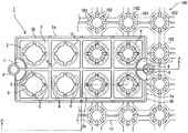
図1は、本発明にかかる地被植物保護基板用表示板の右半分を地被植物保護基板に取付けた状態で示す平面図であり、図2は、図1における地被植物保護基板用表示板のA−A線断面図である。 FIG. 1 is a plan view showing a state in which the right half of a ground cover plant protection substrate display board according to the present invention is attached to the ground cover plant protection substrate, and FIG. 2 is a display for the ground cover plant protection substrate in FIG. It is an AA line sectional view of a board.
地被植物保護基板用表示板1(以下「表示板」と言う。)は、白色等の明視色の平板材2に複数の嵌込み穴3を貫通して形成し、この嵌込み穴3の径は、地被植物保護基板100に直立して形成された筒状の支持部102を挿通して、支持部102の上端部を平板材2の上面よりも突出可能な大きさに形成する。
The ground cover plant protection substrate display board 1 (hereinafter referred to as “display board”) is formed by penetrating a plurality of fitting
地被植物保護基板100は、格子状に形成したフレーム101の各交点に支持部102を直立して構成されており、面状に等間隔に整列配置された支持部102によって被地植物を車両などによる踏圧から保護する。フレーム101と支持部102とは、強化プラスチックなどの高強度樹脂により一体的に形成される。支持部102には、その頂部に滑り止めの凹凸が形成され、側面には荷重を分散して支持する補強用の縦リブ103が裾広がりに突設されている。縦リブ103は支持筒102の等分周位置(図例では8等分周位置)に形成される。
The ground
嵌込み穴3の周縁には、縦リブ103を備えた支持部102と嵌合固定するために、薄肉の弾性固定部4と嵌合用に切り欠いた切込み部5を形成する。具体的には、切込み部5は、支持部102の前後左右位置のそれぞれの縦リブ103と嵌合する位置に配置し、これら切込み部5の間の斜め45度の位置に弾性固定部4を配置する。
A thin
この弾性固定部4は、図1におけるB−B線断面を拡大して図3に示すように、その肉厚Tを他の部分よりも薄く形成し、裾広がりに突設されている縦リブ103の傾斜外側面と干渉して変形することにより、嵌合する高さ位置に応じた拘束力を生じる。
したがって、支持筒102に形成されている全ての縦リブ103に対応して弾性固定部4を配置することでより大きな拘束力を得ることができる。また、嵌込み穴3の周縁から後退または進出した位置で縦リブ103と干渉させたり、弾性固定部4を支持部102の側面に直接干渉する態様に構成することにより、適宜の拘束力を得ることができる。
The
Therefore, a larger restraining force can be obtained by arranging the
この嵌込み穴3に支持部102を挿通して表示板1を押し込むと、図3において破線で図示したように、嵌込み穴3の弾性固定部4が支持部102の側面に形成された縦リブ103によって変形し、嵌込み穴3と支持部102とが嵌合して固定される。この時、表示板1は、支持部102の頂部よりも低い位置で保持されるため、荷重を直接受けることがなく、また路面上方から明視可能に固定することができる。
When the
表示板1の嵌込み穴3の配置については、それぞれ地被植物保護基板100の至近の支持部102と対応する複数の位置に形成する。
例えば、図例のように、1列につき2個の嵌込み穴3を幅方向に4列並べて形成する。この場合、幅方向の端側の列の嵌込み穴3は、中央部の嵌込み穴3よりもその穴径を大きく形成して、成型誤差や外気温等による地被植物保護基板100の伸縮に追従可能に構成する。また、少なくとも至近の2つの支持部102を含むように嵌込み穴3を配置することにより、表示板1が偏った荷重を受けても過大に傾斜することなく支持部102によって保持することができる。
About the arrangement | positioning of the
For example, as shown in the figure, two
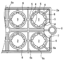
上記した嵌込み穴3の他に、表示板1の平板材2には外周枠2aを形成する。この外周枠2aは、平板材2の周縁からから下方外側へ向かって広がるように形成して平板材2を補強する。また、平板材2と外周枠2aの表面には、低頭の帯状リブ2bを形成する。この帯状リブ2bは、平板材2の周縁に沿って形成すると共に嵌込み穴3を方形に囲む格子模様状に配置される。図例では、断面が略矩形に形成されているが、断面三角形状や断面半円状のカマボコ形に形成してもよい。
In addition to the
さらに、平板材2の底面側には、図4に示すように、嵌込み穴3の周囲に円環状の補強用リブ6を突設する。この補強用リブ6は、図2に断面で示したように、外周枠2aと同じ程度の高さに形成し、嵌込み穴3が形成された平板材2を補強する。さらに、底面側には模様状のリブ6aを縦横に突設して平板材2を補強する。
Further, on the bottom surface side of the
平板材2の幅方向の両端縁中央にはそれぞれ脚部7、7を形成する。脚部7、7は平板材2の端縁から下方に張り出すと共に傾斜させて、下方に向かって縮径する切頭の半円錐筒状に形成する。脚部7、7の下端部には円環状に形成したアンカーピン取付部8、8を設け、このアンカーピン取付部8、8を介して2本のアンカーピン9、9を下地路盤12に打ち込み、表示板1を設置固定することで、平板材の上面を支持部の上端よりも適度に沈降させた状態で確実に固定すると共に、取り外しにくくして持ち去りを防止する。
Leg
図5及び図6は、2枚の表示板1を重ねて示す部分断面正面図及び部分断面側面図である。
脚部7、7は、平板材2の端縁から下方に張り出すと共に半円錐筒状に傾斜して形成されているため、上下の表示板1の脚部7、7が干渉せず、省スペースに積み重ねることができると共に、半円錐筒状の脚部7、7が互いに嵌り合って積み重ねた表示板1が崩れにくい。
5 and 6 are a partial cross-sectional front view and a partial cross-sectional side view showing two display panels 1 in an overlapping manner.
図7は、本発明に係る表示板1を、緑地化した駐車場に適用した状態を示す斜視図である。この駐車場は、一面に地被植物保護基板100を敷設し、その上に芝を植付けて形成されている。
FIG. 7 is a perspective view showing a state in which the display board 1 according to the present invention is applied to a green parking lot. This parking lot is formed by laying a ground cover
一枚の地被植物保護基板100は、運搬時や敷設する際の利便性などから、一辺が数十cmの略方形の格子状フレーム101により形成され、この格子状フレーム101の各交点にそれぞれ支持部102が整列配置される。例えば、この地被植物保護基板100を50cm程度の大きさの方形に形成して、縦横各8列の計64個の支持部102を面状に整列配置する。
One ground cover
この地被植物保護基板100を、図2に示したように平坦に整地した下地路盤12の上に敷設し、図示しない連結具によって互いに結合して適宜の面積と形状とを構成する。そして、支持部102の頂部まで客土11を投入し、客土11の上に芝10を敷き詰めてローラによる転圧を数回行い、芝10を押し込んで緑地を造成する。
The ground cover
こうして敷設した地被植物保護基板100の支持部102を表示板1の嵌込み穴3に挿通し、支持部102の上端部が表示板1の上面よりも突出するまで押し込むと共に弾性固定部4によって嵌込み穴3と支持部102を嵌合する。さらに、アンカーピン取付部8、8を介してアンカーピン9、9を下地路盤12に打ち込み、平板材の上面を支持部の上端よりも適度に沈降させた状態で表示板1を確実に固定する。
The
緑地化駐車場には適宜の位置に車止めが設置されており、この車止めに対応して表示板1を直線状に並べて配置し、駐車場における車両の駐車スペースの区画線を形成する。
また、この表示板1を適宜の位置に配置して、身体障害者用の駐車スペースであることを示す標示を形成することもできる。さらには、ヘリコプターの離着陸場等の標示を形成することもできる。
The greening parking are installed bollard at an appropriate position, the display panel 1 in correspondence with the bollard arranged side by side in a straight line, to form a partition line of the parking space of the vehicle in the parking lot.
Moreover, this display board 1 can be arrange | positioned in a suitable position, and the mark which shows that it is a parking space for a disabled person can also be formed. Furthermore, a sign such as a helicopter take-off and landing field can be formed.
1 地被植物保護基板用表示板
2 平板材
2a 外周枠
2b 帯状リブ
3 嵌込み穴
4 弾性固定部
5 切込み部
6 補強用リブ
6a リブ
7 脚部
8 アンカーピン取付部
9 アンカーピン
10 芝
100 地被植物保護基板
101 フレーム
102 支持部
103 縦リブ
T 肉厚
DESCRIPTION OF SYMBOLS 1 Display board for ground
Claims (4)
前記平板材は、支持部に対応する嵌込み穴を形成し、この嵌込み穴は、支持部を挿通して同平板材の上面より支持部の上端部を突出可能にしてなる地被植物保護基板用表示板。 A plurality of supporting portions planar to align to the clear viewing color display ground cover plant protection substrate made of flat plate material attached to ground cover plant protection substrate to form a road marking which is formed with upright for load bearing In the board,
The flat plate forms a hole the fitting corresponding to the support portion, a hole narrowing the fitting, the protruding possible to ground cover plant protection comprising an upper end portion of the support portion from the upper surface of the inserted through the support portion the flat plate Display board for substrates.
Priority Applications (1)
| Application Number | Priority Date | Filing Date | Title |
|---|---|---|---|
| JP2005275045A JP4652189B2 (en) | 2005-09-22 | 2005-09-22 | Display board for ground cover plant protection board |
Applications Claiming Priority (1)
| Application Number | Priority Date | Filing Date | Title |
|---|---|---|---|
| JP2005275045A JP4652189B2 (en) | 2005-09-22 | 2005-09-22 | Display board for ground cover plant protection board |
Publications (3)
| Publication Number | Publication Date |
|---|---|
| JP2007082462A JP2007082462A (en) | 2007-04-05 |
| JP2007082462A5 JP2007082462A5 (en) | 2008-10-16 |
| JP4652189B2 true JP4652189B2 (en) | 2011-03-16 |
Family
ID=37970080
Family Applications (1)
| Application Number | Title | Priority Date | Filing Date |
|---|---|---|---|
| JP2005275045A Expired - Fee Related JP4652189B2 (en) | 2005-09-22 | 2005-09-22 | Display board for ground cover plant protection board |
Country Status (1)
| Country | Link |
|---|---|
| JP (1) | JP4652189B2 (en) |
Families Citing this family (2)
| Publication number | Priority date | Publication date | Assignee | Title |
|---|---|---|---|---|
| JP5166165B2 (en) * | 2008-08-11 | 2013-03-21 | 株式会社福原鋳物製作所 | Tire guide and green parking lot with it |
| KR102275539B1 (en) * | 2020-11-16 | 2021-07-08 | 손결 | Double-layered mat for protecting grass |
Family Cites Families (3)
| Publication number | Priority date | Publication date | Assignee | Title |
|---|---|---|---|---|
| JP3055979B2 (en) * | 1991-08-30 | 2000-06-26 | 株式会社林物産 | Creeping plant protection material |
| JP3032790B2 (en) * | 1994-05-30 | 2000-04-17 | 株式会社林物産 | Indicators for plant protection treads |
| JP3647912B2 (en) * | 1994-09-26 | 2005-05-18 | 株式会社林物産 | Indicator |
-
2005
- 2005-09-22 JP JP2005275045A patent/JP4652189B2/en not_active Expired - Fee Related
Also Published As
| Publication number | Publication date |
|---|---|
| JP2007082462A (en) | 2007-04-05 |
Similar Documents
| Publication | Publication Date | Title |
|---|---|---|
| US20120121328A1 (en) | Paver installation system | |
| US20040058096A1 (en) | Modular synthetic grass turf assembly | |
| JP5211127B2 (en) | Greening parking lot, planting unit protective material and greening parking lot component material unit | |
| WO2017131948A1 (en) | Method and apparatus for constructing a vehicle parking lot on a land area | |
| US20020029515A1 (en) | Modular synthetic grass turf assembly | |
| US8979420B2 (en) | Marker for permeable paver | |
| JP4652189B2 (en) | Display board for ground cover plant protection board | |
| KR101619285B1 (en) | Sidewalk block with multi-function | |
| JP4818870B2 (en) | Sediment or plant laying unit | |
| JP2007082462A5 (en) | ||
| JP3150919U (en) | Vehicle stopper for ground cover plant protection board | |
| JP4849686B2 (en) | Tree planting protection panel | |
| JP2007107279A (en) | Vehicle stop member for ground cover protecting base plate | |
| US11434655B2 (en) | Headstone marker foundation support with removable insert | |
| US20080010936A1 (en) | Edging Tiles | |
| JP2022079434A (en) | Double-layered mat for protecting grass | |
| KR100712821B1 (en) | Establishment structure of railings | |
| JP3626419B2 (en) | Step board | |
| JP2015124584A (en) | Road surface greening material and road surface with plant | |
| JP2851948B2 (en) | Paving materials for temporary parking | |
| CN220685680U (en) | Assembled concrete pavement structure | |
| CA2420910C (en) | Modular synthetic grass turf assembly | |
| JP3186520U (en) | Parking panel | |
| KR102181285B1 (en) | Supporting mat for grass area | |
| KR102181284B1 (en) | Supporting mat for grass area |
Legal Events
| Date | Code | Title | Description |
|---|---|---|---|
| A521 | Request for written amendment filed |
Free format text: JAPANESE INTERMEDIATE CODE: A523 Effective date: 20080901 |
|
| A621 | Written request for application examination |
Free format text: JAPANESE INTERMEDIATE CODE: A621 Effective date: 20080901 |
|
| A977 | Report on retrieval |
Free format text: JAPANESE INTERMEDIATE CODE: A971007 Effective date: 20101118 |
|
| TRDD | Decision of grant or rejection written | ||
| A01 | Written decision to grant a patent or to grant a registration (utility model) |
Free format text: JAPANESE INTERMEDIATE CODE: A01 Effective date: 20101124 |
|
| A01 | Written decision to grant a patent or to grant a registration (utility model) |
Free format text: JAPANESE INTERMEDIATE CODE: A01 |
|
| A61 | First payment of annual fees (during grant procedure) |
Free format text: JAPANESE INTERMEDIATE CODE: A61 Effective date: 20101215 |
|
| R150 | Certificate of patent or registration of utility model |
Free format text: JAPANESE INTERMEDIATE CODE: R150 Ref document number: 4652189 Country of ref document: JP Free format text: JAPANESE INTERMEDIATE CODE: R150 |
|
| FPAY | Renewal fee payment (event date is renewal date of database) |
Free format text: PAYMENT UNTIL: 20131224 Year of fee payment: 3 |
|
| R250 | Receipt of annual fees |
Free format text: JAPANESE INTERMEDIATE CODE: R250 |
|
| R250 | Receipt of annual fees |
Free format text: JAPANESE INTERMEDIATE CODE: R250 |
|
| R250 | Receipt of annual fees |
Free format text: JAPANESE INTERMEDIATE CODE: R250 |
|
| R250 | Receipt of annual fees |
Free format text: JAPANESE INTERMEDIATE CODE: R250 |
|
| R250 | Receipt of annual fees |
Free format text: JAPANESE INTERMEDIATE CODE: R250 |
|
| R250 | Receipt of annual fees |
Free format text: JAPANESE INTERMEDIATE CODE: R250 |
|
| R250 | Receipt of annual fees |
Free format text: JAPANESE INTERMEDIATE CODE: R250 |
|
| R250 | Receipt of annual fees |
Free format text: JAPANESE INTERMEDIATE CODE: R250 |
|
| R250 | Receipt of annual fees |
Free format text: JAPANESE INTERMEDIATE CODE: R250 |
|
| LAPS | Cancellation because of no payment of annual fees |