JP4650160B2 - Storage equipment - Google Patents
Storage equipment Download PDFInfo
- Publication number
- JP4650160B2 JP4650160B2 JP2005242266A JP2005242266A JP4650160B2 JP 4650160 B2 JP4650160 B2 JP 4650160B2 JP 2005242266 A JP2005242266 A JP 2005242266A JP 2005242266 A JP2005242266 A JP 2005242266A JP 4650160 B2 JP4650160 B2 JP 4650160B2
- Authority
- JP
- Japan
- Prior art keywords
- storage unit
- storage
- wall
- accent
- fixed
- Prior art date
- Legal status (The legal status is an assumption and is not a legal conclusion. Google has not performed a legal analysis and makes no representation as to the accuracy of the status listed.)
- Expired - Fee Related
Links
Images


Landscapes
- Combinations Of Kitchen Furniture (AREA)
Description
本発明は、収納設備に関する。さらに詳しくは、複数の収納ユニットを組み合わせてなる収納設備に関する。 The present invention relates to a storage facility. More specifically, the present invention relates to a storage facility formed by combining a plurality of storage units.
従来、収納設備、とくに、玄関土間と玄関床とにわたるように玄関の壁に沿って設置される玄関収納ユニットは公知であり、例えば、下記特許文献1に記載の技術をあげることができる。すなわち、下記特許文献1の図1、図3に示されているように、上記玄関収納ユニットは、下部収納ユニットと、この下部収納ユニットの上方に間隔を隔てて配置した上部収納ユニットと、玄関の入り口側と反対側の側部に配置して上部収納ユニットや下部収納ユニットと一体に繋がった側部収納ユニットと、下部収納ユニットの上面に設けたカウンターと、カウンターと上部収納ユニットとの間に設けた飾り部とから構成されている。
しかしながら、上記特許文献1に記載の玄関収納ユニットは、上部収納ユニットと下部収納ユニットと側部収納ユニットとが一体に繋がっているため、一人の作業者が上部収納ユニットの側部収納ユニットの反対側を支えている間に、他の作業者が上記上部収納ユニットと下部収納ユニットとの間に、飾り部や棚ユニット等を設置しなければならず、必ずしも施工性がよいものとはいえない。そこで、本発明は上記のように2名の作業者を必要とすることなく、通常、一人の作業者によって作業性よく施工できるとともに、収納性が向上し、かつ、外観に優れた収納設備を提供することを、その課題とする。
However, in the entrance storage unit described in
上記課題を解決するために、本発明においては、つぎのような技術的手段を講じている。すなわち、請求項1に記載の発明によれば、壁面に沿って設けられる収納設備であって、下部収納ユニットと、該下部収納ユニットの上方に間隔をおいて配設される上部収納ユニットと、上記下部収納ユニットと上部収納ユニットとの側面に略コ字形に配置される側部収納ユニットと、アクセントウォールとからなり、該アクセントウォールは、上記上部収納ユニットと下部収納ユニットとの間の壁面に固定され、上記上部収納ユニットはアクセントウォールの上側端面に支持されるとともに、壁面に固定されてなる収納設備において、アクセントウォールは下部収納ユニットの上に載置されその上側端面の水平レベル出しがなされて壁面にビスで固定され、該水平に固定されたアクセントウォールの上側端面の上に上部収納ユニットが載置された状態で壁面にビスで固定されてなることを特徴とする収納設備が提供される。 In order to solve the above problems, the present invention takes the following technical means. That is, according to the first aspect of the present invention, the storage facility is provided along the wall surface, the lower storage unit, and the upper storage unit disposed above the lower storage unit with a space therebetween. The side storage unit includes a side storage unit disposed in a substantially U-shape on the side surfaces of the lower storage unit and the upper storage unit, and an accent wall. The accent wall is formed on a wall surface between the upper storage unit and the lower storage unit. The upper storage unit is fixed and supported on the upper end surface of the accent wall. In the storage facility fixed to the wall surface , the accent wall is placed on the lower storage unit and the upper end surface thereof is leveled out. The upper storage unit is placed on the upper end face of the accent wall that is fixed horizontally with screws. Storage facility characterized by comprising fixed by screws to the wall in a state is provided.
請求項2に記載の収納設備は、請求項1に記載の発明に加えて、上記アクセントウォールがハンギング収納板とされる。上記アクセントウォールとしては、天然木調の化粧板、飾り板、収納板等、上部収納ユニットと下部収納ユニットとの間の壁面の意匠性を向上させるパネル体であれば、とくに限定されるものではないが、上記壁面を収納部として有効に利用するため、ハンギング収納板とすることが好ましい。
In the storage facility according to
請求項3に記載の収納設備は、請求項2に記載の発明に加えて、上記ハンギング収納板が水平方向にレール部を凹設するとともに、このレール部に収納手段がスライド自在に吊持されることが好ましい。収納手段としては、とくに限定されず、収納トレイ、引き出し、小物掛けフック等をあげることができる。 According to a third aspect of the present invention, in addition to the invention according to the second aspect, the hanging storage plate has a rail portion recessed in the horizontal direction, and a storage means is slidably suspended on the rail portion. It is preferable. The storage means is not particularly limited, and examples include a storage tray, a drawer, and a small article hook.
請求項1に記載の発明にかかる収納設備は上記のとおりであり、上部収納ユニットと下部収納ユニットと側部収納ユニットとが略コ字形に配置され、上部収納ユニットと下部収納ユニットとの間にアクセントウォールが壁面に固定されるとともに、上記上部収納ユニットはアクセントウォールの上側端面に支持され、壁面に固定されてなるため、まず、下部収納ユニットの上にアクセントウォールを仮置きして固定手段によって壁面に固定し、つぎにアクセントウォールの上側端面の上に上部収納ユニットを載置して壁面に固定することが可能となり、他の作業者が支えて補助することなく、一人で施工することができる。 The storage facility according to the first aspect of the present invention is as described above, and the upper storage unit, the lower storage unit, and the side storage unit are arranged in a substantially U-shape, and between the upper storage unit and the lower storage unit. The accent wall is fixed to the wall surface, and the upper storage unit is supported on the upper end surface of the accent wall and is fixed to the wall surface. First, the accent wall is temporarily placed on the lower storage unit and fixed by a fixing means. It can be fixed to the wall, and then the upper storage unit can be placed on the upper end surface of the accent wall and fixed to the wall, and it can be installed alone without the support and assistance of other workers. it can.
請求項2に記載の収納設備は上記のとおりであり、請求項1の収納設備の有する効果に加え、上記アクセントウォールがハンギング収納板とされるため、種々の収納手段をスライド自在あるいは移動自在に吊持することができる。したがって、小物類等の収納手段を使い勝手よく、見栄えよく収納することができる。
The storage facility according to
請求項3に記載の収納設備は上記のとおりであり、請求項2の収納設備の有する効果に加え、上記ハンギング収納板が水平方向にレール部を凹設するとともに、このレール部に収納手段がスライド自在に吊持されるため、使い勝手よく、また、見栄えよく、小物類等の収納物を収納することができる。
The storage facility according to
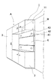
以下、本発明の実施形態について図面を参照して、詳細に説明する。図1は、本発明にかかる収納設備Aを示す斜視図である。図1に示されるように、上記収納設備Aは、上部収納ユニット1、下部収納ユニット2、側部収納ユニット3が壁面Wに沿っていわゆるコ字形に配置され、上部収納ユニット1と下部収納ユニット2との間にはアクセントウォールとしてのハンギング収納板4が設けられている。
Hereinafter, embodiments of the present invention will be described in detail with reference to the drawings. FIG. 1 is a perspective view showing a storage facility A according to the present invention. As shown in FIG. 1, the storage facility A includes an
図1において、上記ハンギング収納板4はビス等の固定手段42によって壁面Wに固定され、ハンギング収納板4の上側端面43には上部収納ユニット1が載置されるとともに同じくビス等の固定手段11によって壁面Wに固定される。また、ハンギング収納板4の水平方向に沿ってレール部41が凹設され、このレール部41には小物掛けフック、引き出し、収納トレイ等の収納手段が吊持される。
In FIG. 1, the hanging
つぎに、本発明にかかる収納設備Aの施工方法について説明する。図2は、最初に、下部収納ユニット2の側面に側部収納ユニット3を並設した状態を示す説明図である。例えば、玄関土間に下部収納ユニット2として下駄箱を設置し、その側面に長尺物等を収納する側部収納ユニット3を設置した場合に相当する。
Below, the construction method of the storage equipment A concerning this invention is demonstrated. FIG. 2 is an explanatory diagram showing a state in which the
ついで、図3に示すように、上記下部収納ユニット2の上にハンギング収納板4を載置して上側端面43の水平レベルを出し、ビス等の固定手段42によって壁面に固定する。このとき、ハンギング収納板4は下部収納ユニット2の上に仮置きできるため、作業者は上記した固定作業を一人で行うことができる。さらに、上部収納ユニット1として、例えば、天袋を施工する場合、図4に示すように、ハンギング収納板4の上側端面43の上に天袋を載置できるため、他の作業者が支えて補助する必要なく、上記と同様に、一人の作業者が天袋をビス等の固定手段11を用いて壁面に固定することができる。
Next, as shown in FIG. 3, the hanging
上記のように施工することによって、上部収納ユニット1と下部収納ユニット2との間の空間はハンギング収納板4によって小物類の収納空間として有効利用できる。図5は、ハンギング収納板4に凹設されたレール部41に収納トレイ5を吊持する状態を示す説明図である。図5において、収納トレイ5の奥側の側壁に設けられた係合部51を上記レール部41にスライド自在に係合することにより、種々の小物類を上記収納トレイ5に使い勝手よく、かつ、見栄えよく収納することができる。
By constructing as described above, the space between the
図5には、収納手段として収納トレイ5が例示されているが、これに限られず、小物掛けフック、引き出し等に係合部を付設して、上記レール部41にスライド自在に係合してもよい。さらに、収納手段に限られず、写真立て、額縁等を吊持することも可能であり、本発明の特許請求の範囲を逸脱しない限り、種々設計変更自由である。
In FIG. 5, the
A 本発明にかかる収納設備
W 壁面
1 上部収納ユニット
11 固定手段
2 下部収納ユニット
3 側部収納ユニット
4 ハンギング収納板
41 レール部
42 固定手段
43 上側端面
5 収納トレイ
51 係合部
A Storage equipment W according to the present
Claims (3)
Priority Applications (1)
| Application Number | Priority Date | Filing Date | Title |
|---|---|---|---|
| JP2005242266A JP4650160B2 (en) | 2005-08-24 | 2005-08-24 | Storage equipment |
Applications Claiming Priority (1)
| Application Number | Priority Date | Filing Date | Title |
|---|---|---|---|
| JP2005242266A JP4650160B2 (en) | 2005-08-24 | 2005-08-24 | Storage equipment |
Publications (2)
| Publication Number | Publication Date |
|---|---|
| JP2007054237A JP2007054237A (en) | 2007-03-08 |
| JP4650160B2 true JP4650160B2 (en) | 2011-03-16 |
Family
ID=37918236
Family Applications (1)
| Application Number | Title | Priority Date | Filing Date |
|---|---|---|---|
| JP2005242266A Expired - Fee Related JP4650160B2 (en) | 2005-08-24 | 2005-08-24 | Storage equipment |
Country Status (1)
| Country | Link |
|---|---|
| JP (1) | JP4650160B2 (en) |
Families Citing this family (1)
| Publication number | Priority date | Publication date | Assignee | Title |
|---|---|---|---|---|
| SE544075C2 (en) | 2018-06-20 | 2021-12-14 | Concentus Properties Ab | A furniture assembly and a method for delivering and mounting such a furniture assembly |
Citations (8)
| Publication number | Priority date | Publication date | Assignee | Title |
|---|---|---|---|---|
| JPS523923U (en) * | 1975-06-24 | 1977-01-12 | ||
| JPS6287552U (en) * | 1985-11-25 | 1987-06-04 | ||
| JPH01141604A (en) * | 1987-11-28 | 1989-06-02 | Ibiden Co Ltd | Fixing plate for furniture unit |
| JPH07222658A (en) * | 1994-02-08 | 1995-08-22 | Itoki Co Ltd | Support member for display wall surface |
| JPH09262142A (en) * | 1996-03-28 | 1997-10-07 | Yamaha Living Tec Kk | System kitchen installing structure |
| JPH1175962A (en) * | 1997-09-12 | 1999-03-23 | Matsushita Electric Works Ltd | Mount structure for wall cabinet |
| JP2002369724A (en) * | 2001-06-14 | 2002-12-24 | Matsushita Electric Works Ltd | Mounting structure for system kitchen |
| JP2005110949A (en) * | 2003-10-07 | 2005-04-28 | Toto Ltd | Wall cabinet |
-
2005
- 2005-08-24 JP JP2005242266A patent/JP4650160B2/en not_active Expired - Fee Related
Patent Citations (8)
| Publication number | Priority date | Publication date | Assignee | Title |
|---|---|---|---|---|
| JPS523923U (en) * | 1975-06-24 | 1977-01-12 | ||
| JPS6287552U (en) * | 1985-11-25 | 1987-06-04 | ||
| JPH01141604A (en) * | 1987-11-28 | 1989-06-02 | Ibiden Co Ltd | Fixing plate for furniture unit |
| JPH07222658A (en) * | 1994-02-08 | 1995-08-22 | Itoki Co Ltd | Support member for display wall surface |
| JPH09262142A (en) * | 1996-03-28 | 1997-10-07 | Yamaha Living Tec Kk | System kitchen installing structure |
| JPH1175962A (en) * | 1997-09-12 | 1999-03-23 | Matsushita Electric Works Ltd | Mount structure for wall cabinet |
| JP2002369724A (en) * | 2001-06-14 | 2002-12-24 | Matsushita Electric Works Ltd | Mounting structure for system kitchen |
| JP2005110949A (en) * | 2003-10-07 | 2005-04-28 | Toto Ltd | Wall cabinet |
Also Published As
| Publication number | Publication date |
|---|---|
| JP2007054237A (en) | 2007-03-08 |
Similar Documents
| Publication | Publication Date | Title |
|---|---|---|
| JP4650160B2 (en) | Storage equipment | |
| JP2018104950A (en) | Mounting method of storage unit | |
| JP2010116772A (en) | Inner wall provided with wardrobe | |
| JP6692143B2 (en) | Storage box suspension structure | |
| JP4518815B2 (en) | Storage shelf and experimental table provided with the same | |
| JP3132898U (en) | Push-in storage unit | |
| JP2010022767A (en) | Locking arm for hanger | |
| KR20170002648U (en) | Door for rest room | |
| JP3216113U (en) | Fixed ceiling-type furniture with adjustable extension | |
| JP2006296905A (en) | Commodity display utensil | |
| JP2006034700A (en) | Closet | |
| KR200323989Y1 (en) | Display rack for wall | |
| JP2007054429A (en) | Fixing structure of upper closet unit | |
| JP2006223459A (en) | Storage apparatus | |
| JP6684653B2 (en) | Book support device for bookcase | |
| JP2016214689A (en) | Storage device | |
| JP6178606B2 (en) | Storage structure | |
| JP2001149145A (en) | Drawer type housing device | |
| JP3115012U (en) | Space use rack | |
| JP2021016635A (en) | Combination desk | |
| JP2012187271A (en) | Display shelf device | |
| KR200363467Y1 (en) | Post arm | |
| JP3125483U (en) | Panel device | |
| JP5358160B2 (en) | Counter support and counter using the same | |
| JP3156940U (en) | Folding self-supporting hanger |
Legal Events
| Date | Code | Title | Description |
|---|---|---|---|
| A621 | Written request for application examination |
Free format text: JAPANESE INTERMEDIATE CODE: A621 Effective date: 20071126 |
|
| A977 | Report on retrieval |
Free format text: JAPANESE INTERMEDIATE CODE: A971007 Effective date: 20090925 |
|
| A131 | Notification of reasons for refusal |
Free format text: JAPANESE INTERMEDIATE CODE: A131 Effective date: 20100727 |
|
| A521 | Written amendment |
Free format text: JAPANESE INTERMEDIATE CODE: A523 Effective date: 20100927 |
|
| TRDD | Decision of grant or rejection written | ||
| A01 | Written decision to grant a patent or to grant a registration (utility model) |
Free format text: JAPANESE INTERMEDIATE CODE: A01 Effective date: 20101116 |
|
| A01 | Written decision to grant a patent or to grant a registration (utility model) |
Free format text: JAPANESE INTERMEDIATE CODE: A01 |
|
| A61 | First payment of annual fees (during grant procedure) |
Free format text: JAPANESE INTERMEDIATE CODE: A61 Effective date: 20101129 |
|
| FPAY | Renewal fee payment (event date is renewal date of database) |
Free format text: PAYMENT UNTIL: 20131224 Year of fee payment: 3 |
|
| LAPS | Cancellation because of no payment of annual fees |