JP4649552B2 - Fishing line lock - Google Patents
Fishing line lock Download PDFInfo
- Publication number
- JP4649552B2 JP4649552B2 JP2005120296A JP2005120296A JP4649552B2 JP 4649552 B2 JP4649552 B2 JP 4649552B2 JP 2005120296 A JP2005120296 A JP 2005120296A JP 2005120296 A JP2005120296 A JP 2005120296A JP 4649552 B2 JP4649552 B2 JP 4649552B2
- Authority
- JP
- Japan
- Prior art keywords
- fishing line
- locking
- sphere
- tip
- binding
- Prior art date
- Legal status (The legal status is an assumption and is not a legal conclusion. Google has not performed a legal analysis and makes no representation as to the accuracy of the status listed.)
- Expired - Fee Related
Links
Images

Landscapes
- Fishing Rods (AREA)
Description
本発明は、釣竿の先端に備えられ、釣糸を結着する釣糸係止具に関するものである。 The present invention relates to a fishing line locking tool that is provided at the tip of a fishing rod and binds a fishing line.
うきや釣針,おもり等の付いた仕掛け(以下、単に釣糸と呼ぶ)を直接釣竿の先端に取付けて使用する釣竿には、釣糸を釣竿に係止するための釣糸係止具が備えられている。特開平07−274779号公報、特開平11−276025号公報に示すように、最近の釣糸係止具には、釣糸が結ばれた部分を回転させるための回転体が備えられている。これは、釣糸が釣竿に絡みついた状態を解消したり、絡みつくのを防止したりするためのものである。 Float and hook, gimmick with a weight or the like (hereinafter, simply referred to as fishing line) to the fishing rod to be used attached to the tip of the direct fishing rod and line clip device for locking the fishing line to a fishing rod is Te Bei Erare Yes. JP-07-274779 discloses, as are shown in JP-A-11-276025, the recent fishline clipping member, the rotation member for rotating a portion fishing line tied is provided. This is for eliminating the state where the fishing line is entangled with the fishing rod or preventing the fishing line from being entangled.
ところが、特開平11−276025号公報の釣糸係止具では、回転体が釣竿の長手方向のみを回転軸としているため、釣糸係止具に結んで垂れ下がった釣糸の縒れを解消したり、防止したりすることができない。また、特開平07−274779号公報の釣糸係止具では、釣糸係止具に結んだ状態のとき、釣糸と釣竿とのなす角が小さいとき、例えば、釣針を握って餌を釣針に付けているときや、釣り人のすぐ近くに釣糸を垂らして魚を釣っているときには、釣糸を結んだ部分よりも円筒部を突出させて備えているために、釣糸が円筒部に架かった状態で下方に垂れ下がってしまう。そのため、円筒管が回転体の回転を妨害し、釣糸の縒れを解消したり、釣糸が釣竿に絡みついたりするのを防止できにくくなる。 However, the line clip device of JP-A-11-276025 discloses, the rotation body is only a rotation axis longitudinal direction of the fishing rod, or eliminate the twist of the fishing line hanging down Nde forming the fishline clipping member, preventing I can't do it. Further, the line clip device of JP-A-07-274779 and JP-a state I binding to the fishing line locking device, when the angle between the fishing line and the fishing rod is small, for example, baited the hook holds the hook and and when that, when hanging a fishing line in the immediate vicinity of the anglers have caught the fish, because they are equipped by projecting the cylindrical portion than the part I'm focusing fishing line, a state in which fishing line is applied to the cylindrical portion in would hang downward. Therefore, cylindrical tube interfere with the rotation of the rotating body, or to eliminate the twisting of the fishing line is less likely prevents fishing line to entanglement One led to a fishing rod.
そこで、さらに、釣糸が釣竿に絡みにくく、絡みついた状態を容易に解消でき、釣糸の縒れを防止することのできる釣糸係止具を提供することを目的とする。 Accordingly, another object of the present invention is to provide a fishing line locking tool that can prevent the fishing line from becoming entangled easily and can prevent the fishing line from becoming tangled easily.
請求項1に記載の第1の発明は、釣糸を係止するために穂先竿の穂先側先端に備えられる、釣糸を係止するための釣糸係止具であって、穂先竿の穂先側先端に装着された本体部と、前記本体部の穂先側端部に突出して取付けられた管状部と、その管状部に回転自在に嵌められて取付けられた球体と、前記球体の表面以内に収まるように、前記球体に備えられ、釣糸を前記球体に直接係止するための係止手段とを備えている。
The first invention according to
したがって、請求項1に記載の発明によれば、回転部分が球体であるため、球体の回転軸は一定とならないで球体は自由に回転する。釣糸が縒れると、球体は縒れを解消するように回転する。また、釣糸が釣竿に絡みついたとき、係止手段に係止された釣糸を軽く引っ張る、または、釣糸の自重により下向きに力が加わると、球体がその力の加わった方向へ回転し、係止手段もその方向へ向きを変える。次に、釣竿の長手方向を軸として球体が回転し、釣糸の絡みつきを解消することができる。
Therefore, according to the invention described in
請求項2に記載の第2の発明は、第1の発明に加え、前記球体の一部が、穂先側先端方向に前記管状部から突出して備えられている。
A second invention according to
したがって、請求項2に記載の発明によれば、球体の一部が、穂先側先端方向に管状部から突出して備えられているため、球体に設けられた係止手段の移動範囲を広げることができる。そのため、係止手段は、釣糸にかかる力の方向に可能な限り傾くことになる。その状態で、釣糸が縒れると、球体は縒れを解消するように、係止手段の方向を軸として回転しやすくなる。また、釣糸が釣竿に絡みついたとき、釣糸を張ると、係止手段が釣糸にかかる力の方向に可能な限り傾くため、球体が回転しやすくなり、釣糸の絡みつきをさらに解消することができる。
Therefore, according to the invention described in
請求項3に記載の第3の発明は、第1または第2の発明に加え、前記係止手段が、前記球体に一端を連結して形成した、釣糸を結び付けるための結着部と、その結着部の他端方向に設けられ、前記結着部に結び付けられた釣糸の移動を制限する係止部と
を備えている。
According to a third aspect of the present invention, in addition to the first or second aspect, the locking means is formed by connecting one end to the sphere , and a binding portion for binding a fishing line, And a locking portion that is provided in the other end direction of the binding portion and restricts the movement of the fishing line that is tied to the binding portion.
したがって、請求項3に記載の発明によれば、釣糸を係止手段に係止する場合には、釣糸に投げ縄結びを作り、その輪に係止部を通過させてから結着部に位置させる。そして、釣糸を引っ張ると投げ縄結びの輪が締まり結着部に結び付けられ釣糸を係止することができる。このとき、釣糸の結び目が結着部をずれて移動しても係止部が結び目の移動を制限し、釣糸が係止手段から外れるのを防ぐ。次に、釣糸を係止手段から取外す場合には、投げ縄結びの輪を広げ、取付ける場合とは逆の手順で結着部から外す。 Therefore, according to the third aspect of the present invention, when the fishing line is locked to the locking means, a lasso is formed on the fishing line, and the locking portion is passed through the ring, and then the fishing line is positioned at the binding portion. Let Then, Ru can be used to lock the fishing line tied to the binder part tight circle of rope knot throw and pull the fishing line. At this time, even if the knot of the fishing line moves out of the binding portion, the locking portion restricts the movement of the knot and prevents the fishing line from coming off from the locking means. Next, when removing the fishing line from the locking means, the loop of the lasso is widened and removed from the binding portion in the reverse procedure to the case of attachment.
請求項4に記載の第4の発明は、第1または第2の発明に加え、前記係止手段が、前記球体の中心を貫通して形成された孔部と、前記管状部の側壁に形成された開口部と、前記孔部に貫通させた釣糸を前記開口部に導く通路部とを備えている。
A fourth invention according to
したがって、請求項4に記載の発明によれば、釣糸を係止手段に取付ける場合には、孔部に釣糸を貫通させ、通路部を通し、開口部を通過させる。そして、通過した釣糸の先端に結び目を作って逆方向へ引くと、結び目が球体の孔部に引っ掛かって釣糸を係止することができる。釣糸を係止手段から取外す場合には、釣糸を孔部へ押し込んで結び目を通路部に通して開口部から出させる。そして、結び目を解く、または露出した釣糸を切断して釣糸を逆方向へ引っ張ると釣糸を外すことができる。 Therefore, according to the fourth aspect of the present invention, when attaching the fishing line to the locking means, the fishing line is passed through the hole, the passage is passed, and the opening is passed. When the pulling tie a knot on the tip of the fishing line passing through the opposite direction, it is possible to knot locking the fishing line caught by the hole portion of the sphere. When the fishing line is removed from the locking means, the fishing line is pushed into the hole , passed through the knot through the passage , and out of the opening. Then, solving the knot, or the fishing line to cut the exposed fishing line fishing line is pulled in the opposite direction Ru can outer Succoth.
請求項5に記載の第5の発明は、前記球体に、螺合して着脱可能とする、第2の係止手段をさらに備えていることを特徴とする請求項4に記載の釣糸係止具。
A fifth invention is according to claim 5, in the sphere, screwed in a detachable line clip according to
したがって、請求項5に記載の発明によれば、第2の係止手段を螺合して着脱することにより、前記係止手段または第2の係止手段のどちらかを選択して釣糸を係止することができる。前記係止手段、または、第2の係止手段には、前述したように釣糸を係止したり取外したりすることが可能となる。
Therefore, according to the fifth aspect of the present invention, the fishing line can be engaged by selecting either the locking means or the second locking means by screwing and detaching the second locking means. Can be stopped. It said locking means, or, in the second locking means, it is possible to and removed or locking the fishing line as described above.
請求項6に記載の第6の発明は、第5の発明に加え、前記球体には、螺孔を備え、
前記第2の係止手段が、釣糸を結び付けるための結着部と、その結着部に設けられた雄螺子部とを備え、その雄螺子部を前記螺孔に着脱自在に螺嵌して取付けられている。
Sixth invention according to
The second locking means includes a binding portion for binding the fishing line and a male screw portion provided in the binding portion, and the male screw portion is detachably screwed into the screw hole. Installed.
したがって、請求項6に記載の発明によれば、第2の係止手段を用いて釣糸を係止する場合には、結着部に形成された雄螺子部を球体の螺孔に螺嵌して第2の係止手段を取付ける。そして、第2の係止手段の結着部に釣糸を取付ける。ここで、結着部とは、輪部、開口部、または孔部であり、釣糸を結着部に結び付けることのできる全ての形状のことである。前述した係止手段を用いて釣糸を係止する場合には、球体から第2の係止手段を取外して、前述したように係止手段に釣糸を係止する。 Therefore, according to the sixth aspect of the present invention, when the fishing line is locked using the second locking means, the male screw portion formed on the binding portion is screwed into the screw hole of the sphere. To attach the second locking means. Then, attach the fishing line in the binder part of the second locking means. Here, a binding part is a ring part, an opening part, or a hole part, and is all the shapes which can bind a fishing line to a binding part. When locking the fishing line using the locking means described above , the second locking means is removed from the sphere, and the fishing line is locked to the locking means as described above.
第1の発明によると、釣糸係止具に結び付けられた釣糸を張ることにより容易に釣糸の絡み、釣糸の縒れを解消することができる。また、釣竿の使用中でも、釣糸が釣竿に絡むのを防止しするとともに、釣糸の縒れを防止することができる。 According to the first invention, it is possible to easily eliminate the entanglement of the fishing line and the twisting of the fishing line by stretching the fishing line tied to the fishing line locking tool. Further, even when the fishing rod is used, it is possible to prevent the fishing line from being entangled with the fishing rod and to prevent the fishing line from being twisted.
第2の発明によると、第1の発明の効果に加え、球体に設けられた係止手段の移動範囲が広がり、釣糸係止具に結び付けられた釣糸を張ると、さらに、容易に釣糸の絡み、釣糸の縒れを解消することができる。また、釣竿の使用中でも、釣糸が釣竿に絡むのを防止しするとともに、釣糸の縒れを防止することができる。 According to the second invention, in addition to the effects of the first invention, the range of movement of the locking means provided on the sphere is widened, and when the fishing line tied to the fishing line locking device is stretched, the fishing line is further easily entangled. , Fishing line drooping can be eliminated. Further, even when a fishing rod is used, it is possible to prevent the fishing line from being entangled with the fishing rod and to prevent the fishing line from being twisted.
第3または第4の発明によると、第1または第2の発明の効果に加え、釣糸を容易に取付け、取外すことができる。 According to the third or fourth invention, in addition to the effects of the first or second invention, the fishing line can be easily attached and detached.
第5または第6の発明によると、第4の発明の効果に加え、前記係止手段と第2の係止手段とを状況に応じて、または、自分の好みにより使い分けることができる。 According to the fifth or sixth invention, in addition to the effect of the fourth invention, in accordance with said locking means and second locking means on the situation, or may be selectively used by their preference.
(第1実施形態)
以下、本発明を具体化した一実施形態を図1及び図2に従って説明する。
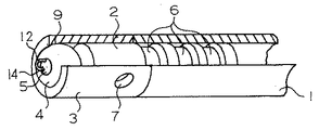
図1に示すように釣竿係止具は、ステンレス、真鍮、アルミニウム等錆びにくい金属でできており、釣竿1の穂先側先端に装着された、本体部としての係止具本体2と、その係止具本体2の穂先側端部に突出して取付けられた、管状部としての円筒管3と、その円筒管3に回転自在に嵌められて取付けられた球体4と、その球体4に設けられ、釣糸を係止するための第2の係止手段としての結着具5とを備えている。
(First embodiment)
Hereinafter, an embodiment of the present invention will be described with reference to FIGS.
As shown in FIG. 1, the fishing rod locking tool is made of a metal that is not easily rusted such as stainless steel, brass, and aluminum. end stop mounted protrudes fore end of the
係止具本体2は、円柱形状に形成されている。その一方には、3列の溝6が形成され、釣竿1の穂先側先端に装着されて取付けられている。係止具本体2の他方には係止具本体2の穂先側端部に突出するように円筒管3が嵌められて取付けられている。円筒管3の側壁には、開口部としての、円形の開口7が形成されている。ここで、円筒管3の穂先側端部は、丸められたり、ラッパ形状に形成されたりしていてもよい。係止具本体2には、断面が円形であり、係止具本体2の一端から軸方向へ向かい開口7に繋がる、通路部としての通路孔8が形成されている。通路孔8は釣糸が通りやすいように緩やかに曲がっている。開口7と、通路孔8の断面形状とは、同じ大きさの円形形状に形成されている。通路孔8、その経路の形状及び開口7は、釣糸が通り易い形状であればどのように形成されていてもよい。
The locking tool
円筒管3の端部内壁周囲には、円筒管3から穂先側先端方向に一部を可能な限り突出させて、球体4を回転自在に嵌めこんで取付けることができるように、湾曲して形成された球体うけ溝9を備えている。その球体うけ溝9に球体4が回転自在に取付けられている。球体4には、その中心を貫通するように、孔部としての係止孔10が形成されている。係止孔10の直径は、取付けられる釣糸の直径より大きく釣糸の結び目の直径より小さい。また、球体4には、前記係止孔10と中心軸を同じくして螺刻された螺孔11が形成されている。螺孔11の位置は、特に係止孔10の位置と同じ位置に形成されていなくてもよい。
Around the inner wall of the end portion of the
結着具5は、U字状に曲折された棒状の結着部12と、その結着部12の一端に設けられ、雄螺子部としての、螺刻された螺子棒13と、その結着部12の他端に形成された球形の係止部14とからなっている。そして、球体4の螺孔11に螺子棒13は着脱可能に螺挿されて取付けることができる。結着部12は、棒状に限らず、例えば、細い板状のもので形成されていてもよい。結着部12の形状も直線状に形成されたり、円を描くように曲げられて形成されたり、円を描いた後捩れるように形成されていてもよい。係止部14は、球形に限らず、結び付けられた釣糸の移動を制限することができれば、つまり、結ばれた釣糸が結着部12から外れないようにする形状であれば、どのような形状に形成されてもよい。
The binding tool 5 includes a rod-shaped binding
次に、上記のように構成された本実施形態の作用及び効果について説明する。
釣糸を結着具5に取付ける場合には、釣糸に投げ縄結びを作り、その輪に係止部14を通過させてから曲折された結着部12に位置させる。そして、釣糸を引っ張ると投げ縄結びの輪が締まり結着部12に結び付けられる。このとき、釣糸の結び目が結着部12をずれて移動しても係止部14が結び目の移動を制限し、釣糸が結着具5から外れない。次に、釣糸を結着具5から取外す場合には、投げ縄結びの輪を広げると、取付ける場合とは逆の手順で結着具5から外すことができる。
Next, the operation and effect of the present embodiment configured as described above will be described.
When the fishing line is attached to the binding tool 5, a lasso is formed on the fishing line, and the locking
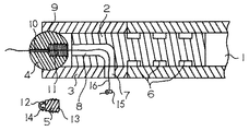
図2に示すように釣糸を球体4の係止孔10に取付ける場合には、係止孔10に釣糸16を貫通させ、通路孔8を通して、開口7から出させる。このとき、釣糸が細く、結び目を作ったとき、係止孔10の直径よりも結び目が小さくなる場合には、結び目より小さい孔を有するもの、ここではビーズを釣糸16に通す。そして、釣糸16の先端に結び目15を作って逆方向へ引くと、結び目15またはビーズが係止孔10に引っ掛かって釣糸16を係止することができる。釣糸16を係止孔10から取外す場合には、釣糸16を係止孔10へ押し込む。そして、係止孔10に係止されていた結び目15を通路孔8に通過させ開口7から出させる。そして、出てきた結び目15を解く、または切断して釣糸を逆方向へ引っ張ると外すことができる。
As shown in FIG. 2, when the fishing line is attached to the locking hole 10 of the
球体4は、回転軸を一定としないため球体4は自在に回転する。釣糸が縒れると、釣糸による縒れを解消しようとする力をうけて、釣糸の垂れ下がった方向を軸として球体4は回転する。そのため、釣糸の縒れを解消することができる。また、釣糸が釣竿1に絡みついたとき、結着具5に係止された釣糸を引っ張ると、球体4がその方向へ回転し、結着具5が引っ張った方向へ向きを変える。そして、さらに引っ張られると、その張力によって釣竿1の長手方向を軸として球体4が回転し、釣糸の絡みつきを解消することができる。また、従来の釣竿で行なわれているように、釣竿1を釣糸の絡みつきを解消する方向へ回すように煽ることにより、釣糸の縒れが解消する方向に球体4が回転し、容易に絡みつきを解消することができる。
したがって、本実施形態の釣糸係止具を利用すれば、従来の釣糸係止具と比較して、さらに、釣糸が釣竿1に絡むのを防止し、また、釣糸の縒れを防止することができる。また、結着具5に取付けるか、または球体4の係止孔10に取付けるかどちらか好きな方を選択して使用することができる。結着具5や係止孔10を使用することにより釣糸を容易に取付け、取外すことができる。
Therefore, if the fishing line locking tool of the present embodiment is used, it is possible to further prevent the fishing line from being entangled with the
(第2実施形態)
次に、別の一実施形態について図3及び図4を用いて説明する。
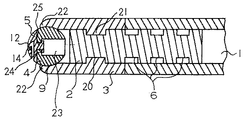
図3に示すように釣竿係止具は、金属製であり、釣竿1の穂先側先端に装着された、本体部としての係止具本体2と、その係止具本体2の穂先側端部に突出して取付けられた、管状部としての円筒管3と、その円筒管3に回転自在に嵌められて取付けられた球体4と、その球体4に設けられ、釣糸を係止するための係止手段としての結着具5とを備えている。
(Second Embodiment)
Next, another embodiment will be described with reference to FIGS.
As shown in FIG. 3, the fishing rod locking tool is made of metal, and is attached to the tip of the
係止具本体2は、円柱形状をしており、一方には、釣竿1に嵌められて取付けられている。係止具本体2の他方には1列の係止溝20が形成されている。円筒管3の内壁には、リング状の突起21が形成されおり、この突起21は前記係止溝20に嵌められ、円筒管3は回転可能に係止具本体2に取付けられている。円筒管3の穂先側端部には、突片としての、内側に湾曲した3つの支持片22が形成されている。支持片22は3つに限定されず、複数であればいくつであってもよい。
The locking tool
円筒管3の端部内壁周囲、及び前記3つの支持片22は、円筒管から穂先側先端方向に一部が突出しており、球体4を回転自在に嵌めこんで取付けることができるように、湾曲して形成された球体うけ溝9を備えている。その球体うけ溝9に、一部を切断された球体4が回転自在に取付けられている。球体4の切断面中心から球体4の中心を貫くように孔23が形成され、切断面の孔23の入口には、その孔23の部分より小さい径の孔を有する結着具止め24を備えている。
End inner wall surrounding the
結着具5は、球体4の切断された部分に取付けられると、球体4が球体形状となるように形成されたものであって、結着部12と係止部14とを備えている。結着具5と球体4とは切断面が合わされて、結着具止め24の孔にリベット形状の止め具25を通され、結着具5の切断面中心に接着されている。そのため、結着具5は球体4に対して止め具25を軸として回転可能である。結着具5と球体4とは回転可能であればどのような取付け方で取付けられてもよい。したがって、一部を切断された球体4と、球体4に取付けられた結着具5とは、全体として球体形状になっており、結着具5が円筒管3に引っ掛かることなく球体4は回転自在である。
The binder 5 is formed so that the
次に、上記のように構成された本実施形態の作用及び効果について説明する。
球体4は、回転軸を一定としないで回転する。また、一部を切断された球体4と、球体4に取付けられた結着具5とは、全体として球体形状になっているため、球体4の回転範囲が広がる。さらに、球体4は円筒管3の側壁のみでなく3つの支持片22によっても円筒管3から穂先側先端方向に一部を可能な限り突出させて回転自在に取付けられている。また、各支持片22の間には、結着具5や結び付けられた釣糸の移動を阻害するものがない。そのため、球体4に設けられた結着具5の移動範囲がさらに広がる。そのため、釣糸が縒れると、係止手段が釣糸にかかる力の方向に可能な限り傾くため、球体はさらに回転し、釣糸の縒れを解消することができる。
Next, the operation and effect of the present embodiment configured as described above will be described.
The
釣糸が縒れると、釣糸による縒れを解消しようとする力をうけて、釣糸の垂れ下がった方向を軸として球体4は回転する。さらに、球体4を補って結着具5も回転する。そのため、釣糸の縒れは解消される。また、釣糸が釣竿1に絡みついたとき、結着具5に係止された釣糸を引っ張ると、球体4が引っ張られた方向へ回転し、結着具5もその方向へ向きを変える。さらに、その張力によって釣竿1の長手方向を軸として球体4または円筒管3が回転し、釣糸の絡みつきを解消することができる。また、従来の釣竿1で行なわれているように、釣竿1を釣糸の絡みつきを解消する方向へ回すように煽ることにより、釣糸の縒れを解消する方向に円筒管3が回転し、容易に絡みつきを解消することができる。
When the fishing line is drawn, the
したがって、本実施形態の釣糸係止具を利用すれば、球体4と独立して、結着具5と円筒管3とが回転するため、さらに効果的に釣糸が釣竿1に絡むのを防止し、釣糸の縒れを防止することができる。また、結着具5に結び付けられた釣糸を張ることにより、さらに、容易に釣糸の絡み、釣糸の縒れを解消することができる。釣竿の使用中でも、釣糸が釣竿1に絡むのを防止しするとともに、釣糸の縒れを防止することができる。
Therefore, if the fishing line locking tool of the present embodiment is used, the binding tool 5 and the
本発明の釣糸係止具は、上述した2つの実施形態に限定されない。例えば、釣糸を貫通させて結び付けることのできる輪部、開口部、または孔部を有する結着部としての結着具を第2の係止手段として用いてもよい。例として、結着具としてU字状の金属棒の両端を球体に取付けたもの、結着具としてP字状に形成された金属棒の一端を球体に取付けたもの、球体に結着具として孔を有する金属板を取付けたもの、それら結着具を回転自在に球体に取付けたもの等である。このようにすると、スナップ金具を使用することにより、さらに容易に釣糸を取付け、取外すことができる。また、球体は、円筒管の穂先側端部に形成された、内側に湾曲した複数の突片と、係止具本体とに回転自在にはさみ付けて取付けられてもよい。 The fishing line locking tool of the present invention is not limited to the two embodiments described above. For example, a binding tool as a binding portion having a ring portion, an opening portion, or a hole portion that can be penetrated and tied with a fishing line may be used as the second locking means . As an example, a U-shaped metal rod with both ends attached to a sphere as a binding tool, a P-shaped metal rod with one end attached to a sphere as a binding tool, and a sphere as a binding tool For example, a metal plate having a hole is attached, or those binders are rotatably attached to a sphere. If it does in this way, a fishing line can be attached and removed still more easily by using a snap metal fitting. Further, the sphere may be attached to a plurality of projecting pieces curved inwardly formed at the tip side end portion of the cylindrical tube and the locking tool main body so as to be freely rotatable.
2 係止具本体
3 円筒管
4 球体
5 係止具
7 開口
8 通路孔
10 係止孔
11 螺孔
12 結着部
13 螺子棒
14 係止部
2 Locking tool body
3 Cylindrical tube
4 Sphere
5 Locking tool
7 Opening
8 passage hole
10 Locking hole
11 Screw holes
12 binding parts
13 Screw rod
14 Locking part
Claims (6)
穂先竿の穂先側先端に装着された本体部と、
前記本体部の穂先側端部に突出して取付けられた管状部と、
その管状部に回転自在に嵌められて取付けられた球体と、
前記球体の表面以内に収まるように、前記球体に備えられ、釣糸を前記球体に直接係止するための係止手段と
を備えていることを特徴とする釣糸係止具。 A fishing line locking tool for locking a fishing line, which is provided at the tip end of the tip of the tip of the head to lock the fishing line,
The main body attached to the tip of the tip of the tip
A tubular part that protrudes and attaches to the tip side end of the main body part;
A sphere that is rotatably fitted and attached to the tubular portion;
To fit within the surface of the sphere, provided in the spherical body, fishline clipping member, characterized in that it comprises a locking means for locking directly fishline to the sphere.
その結着部の他端方向に設けられ、前記結着部に結び付けられた釣糸の移動を制限する係止部と
を備えることを特徴とする請求項1または請求項2に記載の釣糸係止具。 The locking means is formed by connecting one end to the sphere , and a binding portion for binding a fishing line;
The fishing line locking according to claim 1, further comprising a locking portion provided in a direction of the other end of the binding portion and restricting movement of a fishing line tied to the binding portion. Ingredients.
前記管状部の側壁に形成された開口部と、
前記孔部に貫通させた釣糸を前記開口部に導く通路部と
を備えることを特徴とする請求項1または請求項2に記載の釣糸係止具。 The locking means includes a hole formed through the center of the sphere,
An opening formed in the side wall of the tubular portion;
Fishline clipping tool according to claim 1 or claim 2, characterized in that it comprises a passage portion for guiding the fishing line that is passed through the hole to the opening.
The spherical body, screwed to the detachable line clip device according to claim 4, characterized in that it further comprises a second locking means.
前記第2の係止手段は、釣糸を結び付けるための結着部と、その結着部に設けられた雄螺子部とを備え、その雄螺子部を前記螺孔に着脱自在に螺嵌して取付け可能であることを特徴とする請求項5記載の釣糸係止具。 The sphere is provided with a screw hole,
The second locking means includes a binding portion for binding the fishing line and a male screw portion provided in the binding portion, and the male screw portion is detachably screwed into the screw hole. fishline clipping device according to claim 5, wherein the attachable der Rukoto.
Priority Applications (1)
| Application Number | Priority Date | Filing Date | Title |
|---|---|---|---|
| JP2005120296A JP4649552B2 (en) | 2005-03-21 | 2005-03-21 | Fishing line lock |
Applications Claiming Priority (1)
| Application Number | Priority Date | Filing Date | Title |
|---|---|---|---|
| JP2005120296A JP4649552B2 (en) | 2005-03-21 | 2005-03-21 | Fishing line lock |
Publications (3)
| Publication Number | Publication Date |
|---|---|
| JP2006262881A JP2006262881A (en) | 2006-10-05 |
| JP2006262881A5 JP2006262881A5 (en) | 2009-07-23 |
| JP4649552B2 true JP4649552B2 (en) | 2011-03-09 |
Family
ID=37199463
Family Applications (1)
| Application Number | Title | Priority Date | Filing Date |
|---|---|---|---|
| JP2005120296A Expired - Fee Related JP4649552B2 (en) | 2005-03-21 | 2005-03-21 | Fishing line lock |
Country Status (1)
| Country | Link |
|---|---|
| JP (1) | JP4649552B2 (en) |
Family Cites Families (6)
| Publication number | Priority date | Publication date | Assignee | Title |
|---|---|---|---|---|
| JPH0283756U (en) * | 1988-12-14 | 1990-06-28 | ||
| JPH02137867U (en) * | 1989-04-17 | 1990-11-16 | ||
| JPH0367556U (en) * | 1989-11-02 | 1991-07-02 | ||
| JPH0884548A (en) * | 1994-09-14 | 1996-04-02 | Daiwa Seiko Inc | Fishing rod with fishline length control mechanism |
| JP3797513B2 (en) * | 1997-09-10 | 2006-07-19 | 株式会社シマノ | Fishing line locking tool and fishing rod provided with the same |
| JP4249347B2 (en) * | 1999-10-05 | 2009-04-02 | 株式会社シマノ | Fishing line lock |
-
2005
- 2005-03-21 JP JP2005120296A patent/JP4649552B2/en not_active Expired - Fee Related
Also Published As
| Publication number | Publication date |
|---|---|
| JP2006262881A (en) | 2006-10-05 |
Similar Documents
| Publication | Publication Date | Title |
|---|---|---|
| US9173386B2 (en) | Outrigger line lock positioning device | |
| US5666760A (en) | Fishing line lock | |
| CA2744097A1 (en) | Fishing lure with line attachment structure | |
| US20040113006A1 (en) | Fishing reel spool | |
| US5664365A (en) | Trailer fish hook | |
| JP7244311B2 (en) | Artificial baits and split rings for artificial baits | |
| US5444936A (en) | Trolling unit | |
| JP4649552B2 (en) | Fishing line lock | |
| JP2006262881A5 (en) | ||
| JP2007006710A (en) | Double bearing reel | |
| JP2005192477A (en) | Fishing tackle and sinker for use therein | |
| US4546567A (en) | Fishing line sinker | |
| KR20230017071A (en) | A tangle-resistant fishing line connecting hook and a fishing rig comprising the same | |
| US4798022A (en) | Combination fishhook and swivel | |
| JP2000125733A (en) | Device for preventing leader entanglement in fishing tackle | |
| TWI811176B (en) | Whitetail Fish with Tianyang and Whitetail Fish with Fishing Hooks | |
| US3839812A (en) | Anti snagging fishhook | |
| JP3058733U (en) | A tool for preventing hooking of fishing gear | |
| JP7349541B1 (en) | fishing rod | |
| JP3242443U (en) | Fishing line entanglement prevention rod tip | |
| FI105646B (en) | Trolling spoon | |
| JP2020174544A (en) | Squid-fishing tackle | |
| JP2004159616A (en) | Dip net frame | |
| JP4504461B1 (en) | Thread tangle prevention tool | |
| JP3540284B2 (en) | Fishing hook |
Legal Events
| Date | Code | Title | Description |
|---|---|---|---|
| A621 | Written request for application examination |
Free format text: JAPANESE INTERMEDIATE CODE: A621 Effective date: 20080317 |
|
| A521 | Request for written amendment filed |
Free format text: JAPANESE INTERMEDIATE CODE: A523 Effective date: 20090525 |
|
| A977 | Report on retrieval |
Free format text: JAPANESE INTERMEDIATE CODE: A971007 Effective date: 20100225 |
|
| A131 | Notification of reasons for refusal |
Free format text: JAPANESE INTERMEDIATE CODE: A131 Effective date: 20100316 |
|
| A521 | Request for written amendment filed |
Free format text: JAPANESE INTERMEDIATE CODE: A523 Effective date: 20100408 |
|
| A521 | Request for written amendment filed |
Free format text: JAPANESE INTERMEDIATE CODE: A523 Effective date: 20100512 |
|
| A01 | Written decision to grant a patent or to grant a registration (utility model) |
Free format text: JAPANESE INTERMEDIATE CODE: A01 Effective date: 20100914 |
|
| A61 | First payment of annual fees (during grant procedure) |
Free format text: JAPANESE INTERMEDIATE CODE: A61 Effective date: 20100921 |
|
| R150 | Certificate of patent or registration of utility model |
Free format text: JAPANESE INTERMEDIATE CODE: R150 |
|
| FPAY | Renewal fee payment (event date is renewal date of database) |
Free format text: PAYMENT UNTIL: 20131224 Year of fee payment: 3 |
|
| LAPS | Cancellation because of no payment of annual fees |