JP4647568B2 - Injection molding machine - Google Patents
Injection molding machine Download PDFInfo
- Publication number
- JP4647568B2 JP4647568B2 JP2006247351A JP2006247351A JP4647568B2 JP 4647568 B2 JP4647568 B2 JP 4647568B2 JP 2006247351 A JP2006247351 A JP 2006247351A JP 2006247351 A JP2006247351 A JP 2006247351A JP 4647568 B2 JP4647568 B2 JP 4647568B2
- Authority
- JP
- Japan
- Prior art keywords
- nozzle
- mold
- resin
- tip
- cavity
- Prior art date
- Legal status (The legal status is an assumption and is not a legal conclusion. Google has not performed a legal analysis and makes no representation as to the accuracy of the status listed.)
- Expired - Fee Related
Links
Images


Classifications
-
- B—PERFORMING OPERATIONS; TRANSPORTING
- B29—WORKING OF PLASTICS; WORKING OF SUBSTANCES IN A PLASTIC STATE IN GENERAL
- B29C—SHAPING OR JOINING OF PLASTICS; SHAPING OF MATERIAL IN A PLASTIC STATE, NOT OTHERWISE PROVIDED FOR; AFTER-TREATMENT OF THE SHAPED PRODUCTS, e.g. REPAIRING
- B29C45/00—Injection moulding, i.e. forcing the required volume of moulding material through a nozzle into a closed mould; Apparatus therefor
- B29C45/17—Component parts, details or accessories; Auxiliary operations
- B29C45/38—Cutting-off equipment for sprues or ingates
-
- B—PERFORMING OPERATIONS; TRANSPORTING
- B29—WORKING OF PLASTICS; WORKING OF SUBSTANCES IN A PLASTIC STATE IN GENERAL
- B29C—SHAPING OR JOINING OF PLASTICS; SHAPING OF MATERIAL IN A PLASTIC STATE, NOT OTHERWISE PROVIDED FOR; AFTER-TREATMENT OF THE SHAPED PRODUCTS, e.g. REPAIRING
- B29C45/00—Injection moulding, i.e. forcing the required volume of moulding material through a nozzle into a closed mould; Apparatus therefor
- B29C45/17—Component parts, details or accessories; Auxiliary operations
- B29C45/20—Injection nozzles
-
- B—PERFORMING OPERATIONS; TRANSPORTING
- B29—WORKING OF PLASTICS; WORKING OF SUBSTANCES IN A PLASTIC STATE IN GENERAL
- B29C—SHAPING OR JOINING OF PLASTICS; SHAPING OF MATERIAL IN A PLASTIC STATE, NOT OTHERWISE PROVIDED FOR; AFTER-TREATMENT OF THE SHAPED PRODUCTS, e.g. REPAIRING
- B29C45/00—Injection moulding, i.e. forcing the required volume of moulding material through a nozzle into a closed mould; Apparatus therefor
- B29C45/17—Component parts, details or accessories; Auxiliary operations
- B29C45/26—Moulds
-
- B—PERFORMING OPERATIONS; TRANSPORTING
- B29—WORKING OF PLASTICS; WORKING OF SUBSTANCES IN A PLASTIC STATE IN GENERAL
- B29C—SHAPING OR JOINING OF PLASTICS; SHAPING OF MATERIAL IN A PLASTIC STATE, NOT OTHERWISE PROVIDED FOR; AFTER-TREATMENT OF THE SHAPED PRODUCTS, e.g. REPAIRING
- B29C45/00—Injection moulding, i.e. forcing the required volume of moulding material through a nozzle into a closed mould; Apparatus therefor
- B29C45/17—Component parts, details or accessories; Auxiliary operations
- B29C45/46—Means for plasticising or homogenising the moulding material or forcing it into the mould
- B29C45/56—Means for plasticising or homogenising the moulding material or forcing it into the mould using mould parts movable during or after injection, e.g. injection-compression moulding
- B29C45/561—Injection-compression moulding
-
- B—PERFORMING OPERATIONS; TRANSPORTING
- B29—WORKING OF PLASTICS; WORKING OF SUBSTANCES IN A PLASTIC STATE IN GENERAL
- B29C—SHAPING OR JOINING OF PLASTICS; SHAPING OF MATERIAL IN A PLASTIC STATE, NOT OTHERWISE PROVIDED FOR; AFTER-TREATMENT OF THE SHAPED PRODUCTS, e.g. REPAIRING
- B29C45/00—Injection moulding, i.e. forcing the required volume of moulding material through a nozzle into a closed mould; Apparatus therefor
- B29C45/17—Component parts, details or accessories; Auxiliary operations
- B29C45/72—Heating or cooling
-
- B—PERFORMING OPERATIONS; TRANSPORTING
- B29—WORKING OF PLASTICS; WORKING OF SUBSTANCES IN A PLASTIC STATE IN GENERAL
- B29C—SHAPING OR JOINING OF PLASTICS; SHAPING OF MATERIAL IN A PLASTIC STATE, NOT OTHERWISE PROVIDED FOR; AFTER-TREATMENT OF THE SHAPED PRODUCTS, e.g. REPAIRING
- B29C45/00—Injection moulding, i.e. forcing the required volume of moulding material through a nozzle into a closed mould; Apparatus therefor
- B29C45/17—Component parts, details or accessories; Auxiliary operations
- B29C45/26—Moulds
- B29C45/263—Moulds with mould wall parts provided with fine grooves or impressions, e.g. for record discs
-
- Y—GENERAL TAGGING OF NEW TECHNOLOGICAL DEVELOPMENTS; GENERAL TAGGING OF CROSS-SECTIONAL TECHNOLOGIES SPANNING OVER SEVERAL SECTIONS OF THE IPC; TECHNICAL SUBJECTS COVERED BY FORMER USPC CROSS-REFERENCE ART COLLECTIONS [XRACs] AND DIGESTS
- Y10—TECHNICAL SUBJECTS COVERED BY FORMER USPC
- Y10S—TECHNICAL SUBJECTS COVERED BY FORMER USPC CROSS-REFERENCE ART COLLECTIONS [XRACs] AND DIGESTS
- Y10S425/00—Plastic article or earthenware shaping or treating: apparatus
- Y10S425/81—Sound record
Landscapes
- Engineering & Computer Science (AREA)
- Manufacturing & Machinery (AREA)
- Mechanical Engineering (AREA)
- Injection Moulding Of Plastics Or The Like (AREA)
- Moulds For Moulding Plastics Or The Like (AREA)
Description
本発明は、金型を用いて成形体を成形する射出成形機に関し、特に成形体の成形時に、製品となる成形体と共にスプルーが形成されることのない成形効率の向上を図った射出成形機に関する。 The present invention relates to an injection molding machine that molds a molded body using a mold, and in particular, an injection molding machine that improves molding efficiency without forming a sprue together with a molded body that is a product during molding of the molded body. About.
従来から用いられている一般的な射出成形機においては、加熱シリンダ内に原料である粒状の熱可塑性樹脂を送り、加熱シリンダ内に設けられた進退可能なスクリューにより樹脂を溶融しながらスクリュー先端のノズル側に送り出し、スクリューの先端側に設けられたノズルから金型装置のキャビティに溶融樹脂を射出させ、キャビティ内で溶融樹脂を冷却させ固化させた後、金型装置を開き、突出しピンなどにより金型に張り付いている成形物を金型から外すことにより、成形体が成形されている。 In a general injection molding machine that has been used in the past, a granular thermoplastic resin as a raw material is fed into a heating cylinder, and the resin at the tip of the screw is melted by a reciprocating screw provided in the heating cylinder. After feeding to the nozzle side, the molten resin is injected into the cavity of the mold device from the nozzle provided on the tip side of the screw, and after the molten resin is cooled and solidified in the cavity, the mold device is opened, and a protruding pin etc. The molded body is formed by removing the molded product attached to the mold from the mold.
このようなプラスチックなどの成形体を成形する射出成形機においては、その構成を大別すると概ね、型締めユニットと及び射出ユニットから構成されており、型締めユニットにおいては、一般的に固定金型と可動金型を有する金型装置が備えられており、可動金型をトグル機構若しくは直圧方式などの型締めを可能とする可動手段によって、固定金型に対し可動金型を進退させ、型締めの際の型閉じ、及び型開きを行っている。 Such an injection molding machine that molds a molded body such as plastic is roughly composed of a mold clamping unit and an injection unit. In the mold clamping unit, a fixed mold is generally used. And a mold device having a movable mold, and the movable mold is moved forward and backward with respect to the fixed mold by a movable means that enables clamping of the movable mold such as a toggle mechanism or a direct pressure method. The mold is closed and the mold is opened when tightening.
前述した金型の型締め時に形成されるキャビティに、粒状の樹脂であるペレットを溶融樹脂として供給する際には射出ユニットが用いられ、この射出ユニットには、駆動源たるモータなどの駆動手段が備えられ、モータの回転力をプーリやベルトなどを介して順次伝達させ、回転運動を直線運動に変換するボールネジ機構などにより、加熱シリンダ内のスクリューを回転させることにより溶融樹脂を搬送させ、次に溶融樹脂をノズルから型締めユニットに設けられた金型間のキャビティに射出するようになっている。 The cavity formed during mold clamping of the aforementioned mold, the injection unit is used when supplying a pellet which is granular resin as a molten resin, this injection unit, the drive means such as a drive source a motor The rotational force of the motor is sequentially transmitted via pulleys, belts, etc., and the molten resin is conveyed by rotating the screw in the heating cylinder by a ball screw mechanism that converts the rotational motion into linear motion, etc. The molten resin is injected from the nozzle into the cavity between the molds provided in the mold clamping unit.
また、特許文献1には、固定型と可動型とからなるキャビティを形成する一方の固定型の中央に凹所を設け、この凹所と嵌合する圧縮コアを可動型の中央に進退自在に設け、固定型内に挿入したホットノズルの先端を凹所の中央に突出させ、凹所と圧縮コアとの間に圧縮コアで開閉されるランナー部を形成し、圧縮コアの前進時、凹所内に樹脂層を残存させるランナーレス金型が開示されている。
Further, in
前記特許文献1においては、凹所内に樹脂層を残存させた後の成形において、圧縮コア前進時に、凹所内に残存する樹脂は、凹所が凹状になっていること、さらには成形品の肉厚に対する樹脂層の厚みが、約二分の一の寸法となっており(特許文献1の図4参照)、比較的肉厚な樹脂層が凹所内に残ってしまうことは避けられず、残った樹脂層が成形毎に積層して樹脂層の厚さが変化することになる。樹脂層の厚さが変化することは、ゲートの大きさが変化することでもあり、成形品質に悪影響を及ぼすことが考えられる。
In the above-mentioned
また、前述した射出成形機により、音楽や映像などのデータが記録される記録媒体たるコンパクトディスクやビデオディスクなどの肉厚の薄い成形体を成形する場合には、製品となる成形体と連設してスプルーが成形される。このスプルーは、射出成形中に金型内でスプルーが製品となる成形体から切り離されて、型開き後取り出し装置によって成形体とスプルーがそれぞれ金型から取り出されるため、製品となる成形体からスプルーを取り除く作業に時間がかかってしまうと共に、取り除かれたスプルーは製品として利用されるものではないため、無駄に生産されることにより生産コストの上昇を招いてしまう。 In addition, when molding thin molded products such as compact discs and video discs, which are recording media on which data such as music and images are recorded, using the injection molding machine described above, it is connected to the molded product that is the product. A sprue is formed. The sprue is separated from the molded product that is the product in the mold during injection molding, and the molded product and the sprue are each removed from the mold by the take-off device after the mold is opened. Since it takes time to remove the sprue and the removed sprue is not used as a product, it is produced in vain, resulting in an increase in production cost.
本発明は、上記課題を解決するものであり、成形される成形体の品質向上を図ると共に、成形体を成形する際、製品となる成形体とともに一体に成形される製品として利用しない成形部分を、無駄に生産することを防止した生産効率を向上させた射出成形機を提供することを目的とする。 The present invention solves the above-described problems, and aims to improve the quality of a molded body to be molded, and when molding the molded body, a molded portion that is not used as a product molded integrally with the molded body to be a product. An object of the present invention is to provide an injection molding machine with improved production efficiency that prevents wasteful production.
請求項1に係る射出成形機は、固定金型と可動金型とにより形成されるキャビティの前記固定金型側に構成されるノズル受け部を、前記可動金型に向かって僅かに突設させ、前記可動金型に前記ノズル受け部と対向するコア部を進退可能に設け、前記ノズル受け部の先端部とほぼ同一面上にノズルの先端を配置すると共に、溶融樹脂を射出する前記ノズルの先端に対向するコア部の部位に突出部を設け、前記キャビティに射出された樹脂を、前記コア部を前進させると共にこの前進されたコア部に押圧され前記ノズル受け部及びノズルを後退させることで前記樹脂のゲートカットを行い、このゲートカットにより前記ノズル受け部及びノズルの先端に前記樹脂の膜を残存させるように構成したことを特徴とする。
In the injection molding machine according to
上記構成により、ノズルから射出された溶融樹脂は、ゲートからキャビティへと充填され、次に、コア部が前進すると、このコア部の前進動作によって、ノズル受け部及びノズルが押圧され後退され、ゲートカットが行なわれた後、可動金型が後退して型開きが行われる。この際、コア部と、ノズル受け部及びノズルとの間に有する樹脂は、冷却により固体化され、ノズル内に満たされている樹脂と一体となっていることで、ノズル受け部及びノズルの先端に膜状となり残存することから、次サイクル時におけるキャビティへの樹脂の充填時に前記残存した樹脂を、ノズルから供給される溶融樹脂などの熱により溶融し、キャビティに充填する樹脂として用いることで、次の成形サイクル時に成形される成形体の一部として用いることができる。さらに、溶融樹脂を射出する前記ノズルの先端に対向するコア部の部位に突出部を設けたので、突出部がノズルの先端内部に入り込み、成形不良(外観不良)の原因となるノズル先端内部に残存するコールドスラグを減少させることができる。 With the above configuration, the molten resin injected from the nozzle is filled from the gate into the cavity, and then, when the core portion advances, the nozzle receiving portion and the nozzle are pressed and retracted by the advance operation of the core portion, and the gate After the cutting is performed, the movable mold is retracted and the mold is opened. At this time, the resin between the core portion, the nozzle receiving portion and the nozzle is solidified by cooling and integrated with the resin filled in the nozzle, so that the nozzle receiving portion and the tip of the nozzle are integrated. Since the resin remains in the form of a film, when the resin is filled into the cavity in the next cycle, the remaining resin is melted by heat such as a molten resin supplied from a nozzle and used as a resin to fill the cavity. It can be used as a part of a molded article molded during the next molding cycle. Further, since the protrusion is provided at the core portion that opposes the tip of the nozzle for injecting the molten resin, the protrusion enters the tip of the nozzle, and causes a molding defect (appearance defect) inside the nozzle tip. The remaining cold slag can be reduced.
請求項2に係る射出成形機は、請求項1の射出成形機において、前記ノズルにヒータを具備したことを特徴とする射出成形機。
An injection molding machine according to
上記構成により、固体化した残存された膜状の溶融樹脂を、キャビティに充填する際、ノズルに備えたヒータで膜状の樹脂を加熱して溶融することで、ノズルから供給される溶融樹脂と共に膜状の溶融樹脂をキャビティに充填することができる。 With the above configuration, when filling the solidified remaining film-shaped molten resin into the cavity, the film-shaped resin is heated and melted with the heater provided in the nozzle, so that the molten resin supplied from the nozzle The film-like molten resin can be filled into the cavity.
請求項1に係る射出成形機の発明によれば、固定金型と可動金型とにより形成されるキャビティの前記固定金型側に構成されるノズル受け部を、前記可動金型に向かって僅かに突設させ、前記可動金型に前記ノズル受け部と対向するコア部を進退可能に設け、前記ノズル受け部の先端部とほぼ同一面上にノズルの先端を配置すると共に、溶融樹脂を射出する前記ノズルの先端に対向するコア部の部位に突出部を設け、前記キャビティに射出された樹脂を、前記コア部を前進させると共にこの前進されたコア部に押圧され前記ノズル受け部及びノズルを後退させることで前記樹脂のゲートカットを行い、このゲートカットにより前記ノズル受け部及びノズルの先端に前記樹脂の膜を残存させるように構成したので、残存した樹脂を、次の成形サイクル時に成形される成形体の一部として用いることができる。従って、成形体を成形する際、製品となる成形体とともに一体に成形される製品として利用しない成形部分が、スプルーとして無駄に生産されることを防止できるので、生産効率を向上することができる。
According to the invention of the injection molding machine according to
請求項2に係る射出成形機の発明によれば、請求項1記載の射出成形機において、前記ノズルにヒータを具備したものである。これにより、固体化した残存された膜状の樹脂を成形体の一部として利用することができる。
According to the invention of the injection molding machine according to
以下、本発明を実施するための最良の形態としての実施例を図1〜図6により以下に説明する。もちろん、本発明は、その発明の趣旨に反しない範囲で、実施例において説明した以外の構成のものに対しても容易に適用可能なことは説明を要するまでもない。 Hereinafter, the best mode for carrying out the present invention will be described with reference to FIGS. Needless to say, the present invention can be easily applied to configurations other than those described in the embodiments without departing from the spirit of the invention.
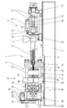
図1は本発明の一例を示す射出成形機の金型を型開きした状態を示す一部切欠き側面図、図2〜図6は射出成形機に構成される金型装置の要部を示す拡大断面図である。図1に示すように、射出成形機1は機台2を有し、この機台2上に射出ユニット3、型締めユニット4、金型装置5が配置されている。
FIG. 1 is a partially cutaway side view showing a state in which a mold of an injection molding machine showing an example of the present invention is opened, and FIGS. 2 to 6 show a main part of a mold apparatus configured in the injection molding machine. It is an expanded sectional view. As shown in FIG. 1, the
射出ユニット3の構成について以下に詳述すると、射出ユニット3には、この射出ユニット3のスクリュー6を回転させ金型のキャビティCに溶融樹脂を送り出すようになっており、射出ユニット3の上方側には粒状の原料である樹脂(ペレット)が投入されるホッパ7を有し、このホッパ7からその下方に設けられた筒型の加熱シリンダ8内に粒状の樹脂が自重により落下して投入されるようになっている。
The configuration of the injection unit 3 will be described in detail below. In the injection unit 3, the
射出ユニット3では、スクリュー6を回転させると共に加熱シリンダ8内に供給され加熱された溶融樹脂の計量などを行うものであり、駆動源たるスクリュー回転駆動モータ9を備え、このスクリュー回転駆動モータ9の回転軸部10に固定されているプーリ11が、計量駆動用タイミングベルト12を介してスクリュー6の後側を回転することで、スクリュー6は連動して回転される。
The injection unit 3 rotates the
また、射出ユニット3の後方(図1に示す右側)には、射出駆動用モータが、機台2上に載置されている後側支持フレーム13に固定されており、射出駆動用モータのプーリ、射出駆動用タイミングベルトなどからなる駆動伝達機構を介して、後述するボールネジユニットに構成されるボールネジ部14を回動するようになっており、機台2上に固定されている前側支持フレーム15と後側支持フレーム13とは円柱状のタイバー17で連結されている。
An injection driving motor is fixed to the
ここで、ボールネジユニットについて説明すると、ボールネジユニットに構成されるナット部16は、スクリュー6を回転自在に保持すると共に前記タイバー17にガイドされたスクリュー保持プレート18に取り付けられている。また、スクリュー回転駆動モータ9はスクリュー保持プレート18に固定されており、射出駆動用モータとボールネジユニットにより、ナット部16が前進されると、キャビティCに溶融樹脂を射出し、一方、後退すると、キャビティCに射出される樹脂の可塑化・計量を行なうようになっている。
Here, the ball screw unit will be described. A
また、ボールネジ部14は、ボールネジ部14を正逆回転させることによりナット部16を前後方向に進退させるものであって、後側支持フレーム13に回動自在に軸支されており、ボールネジ部14の軸線方向(図1に示す左右方向)に進退するナット部16の可動時には、このナット部16とボールネジ部14との間に有する図示しない溝部の間を鋼球が転がりながら繰り返し通過することで、ボールネジ部14に対してナット部16がスムーズに進退するものである。
The
また、前側支持フレーム15に固定されている加熱シリンダ8内に回動可能に設けられたインライン式のスクリュー6は、スクリュー回転駆動モータ9を駆動源として回転されるが、スクリュー6は、スクリュー6と加熱シリンダ8との間に供給されてきた溶融樹脂をスクリュー6先端側のノズル20に移動させる機能を有する一方で、前進することで溶融樹脂をキャビティCに注入するプランジャとしての機能もある。なお、ノズル20にはヒータが具備されると共に、ノズル20の後部は、加熱シリンダ8内の内側先端側に螺合され、また、可動金型21と固定金型22とからなるキャビティCには、ノズル20の先端から溶融樹脂が供給される。なお、ノズル20に具備されたヒータは、図示はしないがキャビティCに充填されるノズル20内の溶融樹脂の温度の低下を防止するものである。
The
次に上記射出成形機に構成される型締めユニット4の構成について以下に説明する。型締めユニット4は、固定金型22に対し可動金型21を前進後退させ型締め(型閉じ)及び型開きを行う型締め駆動装置23を備え、金型の型開き時に可動金型21内に貼着している成形体を突き出して取り出す図示しないエジェクト駆動装置を備えている。
Next, the configuration of the mold clamping unit 4 configured in the injection molding machine will be described below. The mold clamping unit 4 includes a mold
また、型締めユニット4には、テールストック24、固定ダイプレート25、可動ダイプレート26が機台2上に設けられており、機台2上に固定されたテールストック24と固定ダイプレート25とは、複数の円柱型のタイロッド27で連結されている。なお、可動ダイプレート26には、ボールネジ機構28により後述するコア部を進退させる駆動装置29が取り付けられている。
Further, the mold clamping unit 4 is provided with a
次に、型締め駆動装置23について以下に説明する。30は、テールストック24の上部に固定されると共に、固定金型22に対し可動金型21の型締めを行う駆動源たる型締め用モータである。型締め駆動装置23においては、プーリ31が型締め用モータ30に回動自在に取り付けられており、型締め用モータ30が型締め用タイミングベルト31Aを介してテールストック24に軸支されているプーリ32を回転させ、こうした駆動を伝達するための駆動伝達機構によりトグル機構33に駆動力を伝達させる。そして、型締め用モータ30の駆動に伴い、トグル機構33に構成された複数のアームからなるリンクアーム34が縮められ型開きした状態(図1に示す状態)から、型閉じを行う際には、リンクアーム34が直線状に伸びることで、固定金型22に対し可動金型21の型閉じ(型締め)が行われる。なお、型閉じされた前記可動金型21を型開きする際には、型締め用モータ30の回転方向を型締め時の逆回転で行うことで型開きされる。
Next, the mold
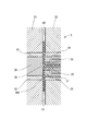
次に、金型装置5について説明する。この金型装置5は、図1に示すように、可動ダイプレート26に固定された可動金型21、固定ダイプレート25に固定された固定金型22を備え、可動ダイプレート26の進退に伴い、固定金型22に対して可動金型21が進退し、型開閉が行われるようになっている。また、図2に示すように、固定金型22の略中央部にはノズル20の先端が挿通可能に、ノズル挿入孔35が形成されている。
Next, the
また、可動金型21には、駆動用モータを構成する駆動装置29によりボールネジ機構28を介して前後に進退されるコア部36が組み付けられており、このコア部36が前進することにより、固定金型22とノズル20との間に介在されると共に可動金型21に向かって僅かに突設して配置されたノズル受け部37の先端を押圧して後退するようになっている。また、突出部38は、溶融樹脂を射出するノズル20の先端に対向するようにして、コア部36に設けられている。
Further, the
また、突出部38が一体に設けられたコア部36と可動金型21との間には、金型内の成形体を突き出して取り出すエジェクトスリーブ42を有し、また、ノズル受け部37と固定金型22との間には、スタンパ取り付け用のスタンパホルダ39を有している。
In addition, an
なお、ノズル20及びノズル受け部37の先端は、図2に示すように、固定金型22におけるキャビティCを形成する平面状部分(スタンパ)40と、略同一平面状に配置されており、より詳細には、平面状部分40よりも、コア部36側に僅かに突出している。
As shown in FIG. 2, the tip of the
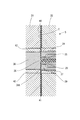
次に、本発明の一例における金型の動作について、図2〜図6に基づき以下に説明する。なお、前記動作順は、図2〜図6の順序となっており、図3は図2に示したキャビティに溶融樹脂が充填されている途中状態であり、図4は所定量の溶融樹脂がキャビティに充填された状態で型締めされたた状態、図5はコア部が前進しゲートカットした状態、図6はゲートカット完了後に金型を型開きした状態を示している。 Next, operation | movement of the metal mold | die in an example of this invention is demonstrated below based on FIGS. The order of operation is the order of FIGS. 2 to 6, FIG. 3 is a state in the middle of filling the cavity shown in FIG. 2 with molten resin, and FIG. FIG. 5 shows a state where the mold is clamped in a state where the cavity is filled, FIG. 5 shows a state where the core portion has advanced and gate cut, and FIG. 6 shows a state where the mold is opened after the gate cut is completed.
図3に示すように、ノズル20から射出された溶融樹脂がキャビティCに充填され続け、図4に示すように所定量の溶融樹脂がキャビティCに充填されると、この工程とほぼ同時に固定金型22に対して可動金型21が型締めされる。続いて、駆動装置29の駆動によりボールネジ機構28を介してコア部36が前進(図5に示す右方向)され、図5に示すように、コア部36の前進に伴い、ノズル受け部37及びノズル20が押圧され後退し、ゲートカットが行なわれる。そして、図6に示すように、固定金型22に対して可動金型21が型開きされ、成形された成形体がキャビティCから取り出される。
As shown in FIG. 3, when the molten resin injected from the
なお、図5に示すゲートカット時には、溶融樹脂はコア部36により圧縮され、図6に示すように、型開きされた際であっても、ゲートカットされた溶融樹脂は、ノズル20及びノズル受け部37の先端部に膜として残存し、この残存した溶融樹脂は、次の成形サイクル時、成形体の一部として用いられる。
When the gate cut shown in FIG. 5 is performed, the molten resin is compressed by the
ここで、コア部36に突出部38を設けた理由を以下に3つ(コールドスラグによる外観不良の改善、射出負荷の低減、ゲートの改善)説明する。
Here, three reasons for providing the projecting
まず、コールドスラグによる外観不良の改善について説明すると、コールドスラグが生ずると、冷えた樹脂がキャビティCに流れ込んでしまうことで、キャビティCで成形される成形体が外観不良となってしまうが、突出部38をノズル20の先端内部に入り込むように、コア部36に突出部38を設けたことで、外観不良の原因となるノズル20の先端内部に残存するコールドスラグを減少させることができる。続いて、射出負荷の低減について説明すると、前記コールドスラグによる外観不良の改善と同様に、ノズル20先端内部に残存するコールドスラグを減少させることにより、初期の射出抵抗(樹脂のせん断応力)の上昇による成形体の分子配合、複屈折を抑えることができる。続いて、ゲート41の改善について説明すると、ノズル20の先端部を、図5に示すように、突出部38でシャットすることで、スクリュー6側のノズル20から供給される溶融樹脂の流入・圧力伝播による影響を抑え、ゲートカット前のコア部36とノズル20間の溶融樹脂量を削減でき、応力残留及びマイクロクラック発生による成形体の割れや、成形体の貼り合わせ不良の原因となるカットバリを防止でき、且つその結果として、ゲートカット後に残存する樹脂の膜厚を薄くすることができる。
First, the improvement of the appearance defect due to cold slag will be described. When cold slag is generated, the cooled resin flows into the cavity C, so that the molded body molded in the cavity C becomes defective in appearance. By providing the protruding
本実施例における射出成形機1によれば、固定金型22と可動金型21とにより形成されるキャビティCの固定金型22側に構成されるノズル受け部37の先端を、可動金型21に向かって僅かに突設させ、可動金型21にノズル受け部37と対向するコア部36を進退可能に設け、ノズル受け部37の先端部とほぼ同一面上にノズル20の先端を配置すると共に、溶融樹脂を射出するノズル20の先端に対向するコア部36の部位に突出部38を設け、キャビティCに射出された樹脂を、コア部36を前進させると共にこの前進されたコア部36に押圧されノズル受け部37及びノズル20を後退させることで樹脂のゲートカットを行い、このゲートカットによりノズル受け部37及びノズル20の先端に樹脂の膜を残存させるように構成したものである。これにより、ノズル20から射出された溶融樹脂は、ゲート41からキャビティCへと充填され、次にコア部36が前進すると、このコア部36の前進動作によって、ノズル受け部37及びノズル20が押圧され後退され、ゲートカットが行なわれた後、可動金型21が後退して型開きが行われる。この際、コア部36と、ノズル受け部37及びノズル20との間に有する樹脂は、冷却により固体化され、ノズル20内に満たされている樹脂と一体となっていることで、ノズル受け部37及びノズル20の先端に膜状となり残存することから、残存した樹脂を、次サイクル時におけるキャビティCへの樹脂の充填時に、ノズル20から供給される溶融樹脂などの熱により溶融し、キャビティCに充填する樹脂として用いることで、次の成形サイクル時に成形される成形体の一部として用いることができる。従って、残存した樹脂を、次の成形サイクル時に成形される成形体の一部として用いることができ、例えば、音楽や映像などのデータが記録される記録媒体(コンパクトディスクやビデオディスク)などの肉厚の薄い平板状の成形体を成形する際、製品となる成形体とともに一体に成形される製品として利用しない成形部分が、スプルーとして無駄に生産されることを防止できるので、生産効率の向上及び製造コストを抑えることができる。さらに、溶融樹脂を射出するノズル20の先端に対向するコア部36の部位に突出部38を設けたので、突出部38がノズル20の先端内部に入り込むように配置することで、外観不良の原因となるノズル20の先端内部に残存するコールドスラッグを減少させることができ、且つ、ノズル受け部37及びノズル20の先端に残存する樹脂の膜厚が所定の薄さになるよう調整することができる。よって、樹脂を、ノズル受け部37及びノズル20に薄い膜として残存させることができるので、従来のように、残存する樹脂層の厚さが変化することで、成形体の品質に悪影響を及ぼすことを防止することができる。
According to the
さらに、ノズル20にヒータを具備したので、冷却により固体化して残存された膜状の樹脂をキャビティCに充填する際、ノズル20に備えたヒータで膜状の溶融樹脂を加熱して溶融することで、ノズル20から射出により供給される溶融樹脂と共に膜状の樹脂をキャビティCにスムーズに充填することができる。よって、残存された膜状の樹脂を成形体の一部として利用することができる。
Further, since the
以上、本実施例の一実施例を詳述したが、本発明は、前記実施例に限定されるものではなく、本発明の要旨の範囲内で種々の変形実施が可能である。本実施例においては、固定金型に対して可動金型を行う機構にトグル機構を用いている例を示しているが、これに特に限定するものではなく、これに代えて電動モータによる直圧式の型締め/型開き装置、或いは油圧式の装置であっても適用可能である。 Although one embodiment of the present embodiment has been described in detail above, the present invention is not limited to the above-described embodiment, and various modifications can be made within the scope of the gist of the present invention. In the present embodiment, an example is shown in which a toggle mechanism is used as a mechanism for performing a movable mold with respect to a fixed mold, but the present invention is not particularly limited thereto, and instead, a direct pressure type using an electric motor. Even a mold clamping / mold opening device or a hydraulic device can be applied.
1 射出成形機
20 ノズル
21 可動金型
22 固定金型
36 コア部
37 ノズル受け部
38 突出部
C キャビティ
DESCRIPTION OF
Claims (2)
Priority Applications (7)
| Application Number | Priority Date | Filing Date | Title |
|---|---|---|---|
| JP2006247351A JP4647568B2 (en) | 2006-09-12 | 2006-09-12 | Injection molding machine |
| TW096129754A TW200827139A (en) | 2006-09-12 | 2007-08-10 | Injection molding machine |
| EP07805952A EP2062716A1 (en) | 2006-09-12 | 2007-08-21 | Injection molding machine |
| CN2007800313837A CN101505940B (en) | 2006-09-12 | 2007-08-21 | Injection molding machine |
| KR1020087031025A KR20090060217A (en) | 2006-09-12 | 2007-08-21 | Injection molding machine |
| US12/374,119 US8016588B2 (en) | 2006-09-12 | 2007-08-21 | Injection molding machine |
| PCT/JP2007/066151 WO2008032533A1 (en) | 2006-09-12 | 2007-08-21 | Injection molding machine |
Applications Claiming Priority (1)
| Application Number | Priority Date | Filing Date | Title |
|---|---|---|---|
| JP2006247351A JP4647568B2 (en) | 2006-09-12 | 2006-09-12 | Injection molding machine |
Publications (3)
| Publication Number | Publication Date |
|---|---|
| JP2008068455A JP2008068455A (en) | 2008-03-27 |
| JP2008068455A5 JP2008068455A5 (en) | 2009-05-07 |
| JP4647568B2 true JP4647568B2 (en) | 2011-03-09 |
Family
ID=39183598
Family Applications (1)
| Application Number | Title | Priority Date | Filing Date |
|---|---|---|---|
| JP2006247351A Expired - Fee Related JP4647568B2 (en) | 2006-09-12 | 2006-09-12 | Injection molding machine |
Country Status (7)
| Country | Link |
|---|---|
| US (1) | US8016588B2 (en) |
| EP (1) | EP2062716A1 (en) |
| JP (1) | JP4647568B2 (en) |
| KR (1) | KR20090060217A (en) |
| CN (1) | CN101505940B (en) |
| TW (1) | TW200827139A (en) |
| WO (1) | WO2008032533A1 (en) |
Citations (3)
| Publication number | Priority date | Publication date | Assignee | Title |
|---|---|---|---|---|
| JPS5857929A (en) * | 1981-09-23 | 1983-04-06 | デイスコビジヨン・アソシエイツ | Aggregate body of valve |
| JPH08281714A (en) * | 1995-04-17 | 1996-10-29 | Nissei Plastics Ind Co | Runnerless mold |
| JP2003053786A (en) * | 2001-08-14 | 2003-02-26 | Sony Corp | Injection molding machine for molding resin substrate |
Family Cites Families (19)
| Publication number | Priority date | Publication date | Assignee | Title |
|---|---|---|---|---|
| US3989436A (en) * | 1975-12-18 | 1976-11-02 | Rca Corporation | Apparatus for producing injection molded and centrally apertured disc records |
| US4372741A (en) * | 1980-10-31 | 1983-02-08 | Discovision Associates | Hot sprue valve assembly for an injection molding machine |
| US4618466A (en) * | 1982-10-21 | 1986-10-21 | Apsley Metals Limited | Moulding apparatus |
| JP2642158B2 (en) * | 1988-08-16 | 1997-08-20 | 住友重機械工業株式会社 | Mold for optical disk substrate molding |
| JP2710254B2 (en) * | 1989-11-01 | 1998-02-10 | 住友重機械工業株式会社 | Injection mold for shearing the film gate inside the mold |
| EP0596413B1 (en) * | 1992-11-04 | 1998-12-16 | TDK Corporation | Method of making a plurality of optical record disc substrates, and an apparatus therefore |
| DE69414285T2 (en) * | 1993-02-25 | 1999-04-22 | Sony Electronics Inc., Park Ridge, N.J. | Pouring devices |
| JP2944359B2 (en) * | 1993-03-23 | 1999-09-06 | 株式会社精工技研 | Base injection mold |
| JPH10154359A (en) * | 1996-11-21 | 1998-06-09 | Matsushita Electric Ind Co Ltd | Method for molding thin parts and apparatus therefor |
| US6002663A (en) * | 1997-04-17 | 1999-12-14 | Imation Corp. | Hubless optical disc having low radial runout and method of manufacture |
| CN2329505Y (en) * | 1998-04-27 | 1999-07-21 | 李洲企业股份有限公司 | Mould with automatic cutting waste material |
| TR200100777T2 (en) * | 1998-09-18 | 2001-12-21 | Rohm Gmbh & Co. Kg | Forming tool for information carrier raw floppy disks. |
| JP2002240101A (en) * | 2000-12-15 | 2002-08-28 | Sony Corp | Disk board and mold apparatus for injection molding the same, robot for fetching disk board |
| WO2004045822A1 (en) * | 2002-11-18 | 2004-06-03 | Sumitomo Heavy Industries, Ltd. | Molding die, molding method, disk substrate, and molding machine |
| CN100351064C (en) * | 2003-03-03 | 2007-11-28 | 松下电器产业株式会社 | Die for molding disk substrate and method of manufacturing disk substrate |
| JP2005190632A (en) * | 2003-12-26 | 2005-07-14 | Technos:Kk | Optical disk molding die on which diamond like carbon is film-deposited and optical disk molding method using the same |
| CN1741887A (en) * | 2004-03-31 | 2006-03-01 | 住友重机械工业株式会社 | Molding die of disc, molding and moling device |
| CN100469553C (en) * | 2004-03-31 | 2009-03-18 | 住友重机械工业株式会社 | Metal mold device, mould product, its forming method and forming machine |
| WO2006054647A1 (en) * | 2004-11-18 | 2006-05-26 | Matsushita Electric Industrial Co., Ltd. | Injection molding machine, injection molding method, and injection molding die |
-
2006
- 2006-09-12 JP JP2006247351A patent/JP4647568B2/en not_active Expired - Fee Related
-
2007
- 2007-08-10 TW TW096129754A patent/TW200827139A/en not_active IP Right Cessation
- 2007-08-21 WO PCT/JP2007/066151 patent/WO2008032533A1/en active Application Filing
- 2007-08-21 US US12/374,119 patent/US8016588B2/en not_active Expired - Fee Related
- 2007-08-21 KR KR1020087031025A patent/KR20090060217A/en not_active Application Discontinuation
- 2007-08-21 CN CN2007800313837A patent/CN101505940B/en not_active Expired - Fee Related
- 2007-08-21 EP EP07805952A patent/EP2062716A1/en not_active Withdrawn
Patent Citations (3)
| Publication number | Priority date | Publication date | Assignee | Title |
|---|---|---|---|---|
| JPS5857929A (en) * | 1981-09-23 | 1983-04-06 | デイスコビジヨン・アソシエイツ | Aggregate body of valve |
| JPH08281714A (en) * | 1995-04-17 | 1996-10-29 | Nissei Plastics Ind Co | Runnerless mold |
| JP2003053786A (en) * | 2001-08-14 | 2003-02-26 | Sony Corp | Injection molding machine for molding resin substrate |
Also Published As
| Publication number | Publication date |
|---|---|
| WO2008032533A1 (en) | 2008-03-20 |
| US20090169671A1 (en) | 2009-07-02 |
| US8016588B2 (en) | 2011-09-13 |
| CN101505940A (en) | 2009-08-12 |
| TWI308885B (en) | 2009-04-21 |
| JP2008068455A (en) | 2008-03-27 |
| CN101505940B (en) | 2011-11-16 |
| KR20090060217A (en) | 2009-06-11 |
| EP2062716A1 (en) | 2009-05-27 |
| TW200827139A (en) | 2008-07-01 |
Similar Documents
| Publication | Publication Date | Title |
|---|---|---|
| JP3536492B2 (en) | Injection mold and injection molding method using the mold | |
| KR100872323B1 (en) | Molding method and molding machine | |
| JP4647568B2 (en) | Injection molding machine | |
| JP5022734B2 (en) | Injection molding machine | |
| CN107775879B (en) | Injection molding machine | |
| JP2923220B2 (en) | Method and apparatus for molding resin material containing long glass fiber | |
| JP2631064B2 (en) | Flow molding method | |
| JP6146859B2 (en) | Injection molding machine | |
| JP6845683B2 (en) | Injection molding machine and injection molding method | |
| JP3712331B2 (en) | Core compression injection molding machine | |
| JPH11333898A (en) | Mold for injection molding | |
| JP5566015B2 (en) | Injection mold | |
| JP2004243534A (en) | Molding machine for molding plurality of materials and method for molding plurality of materials | |
| JP3146473B2 (en) | Link by injection molding | |
| JP2003211513A (en) | Injection molding machine | |
| JP3985991B2 (en) | Substrate forming method for information recording medium | |
| JP2003077178A (en) | Optical disk, its manufacturing method and device | |
| JP3027542B2 (en) | Local pressurized injection molding machine | |
| JP3006989B2 (en) | Method for manufacturing optical disk substrate | |
| JP3132605B2 (en) | Injection molding method | |
| JP2003311790A (en) | Mold device for injection molding and injection molding method | |
| JP2007296780A (en) | Control method for injection molding machine | |
| JP2001277297A (en) | Injection molding method and apparatus therefor | |
| JP2008238555A (en) | Injection molding die and manufacturing method of injection-molded object | |
| JP2004291354A (en) | Sandwich injection molding machine |
Legal Events
| Date | Code | Title | Description |
|---|---|---|---|
| A521 | Written amendment |
Free format text: JAPANESE INTERMEDIATE CODE: A523 Effective date: 20090319 |
|
| A621 | Written request for application examination |
Free format text: JAPANESE INTERMEDIATE CODE: A621 Effective date: 20090319 |
|
| TRDD | Decision of grant or rejection written | ||
| A01 | Written decision to grant a patent or to grant a registration (utility model) |
Free format text: JAPANESE INTERMEDIATE CODE: A01 Effective date: 20101109 |
|
| A01 | Written decision to grant a patent or to grant a registration (utility model) |
Free format text: JAPANESE INTERMEDIATE CODE: A01 |
|
| A61 | First payment of annual fees (during grant procedure) |
Free format text: JAPANESE INTERMEDIATE CODE: A61 Effective date: 20101208 |
|
| FPAY | Renewal fee payment (event date is renewal date of database) |
Free format text: PAYMENT UNTIL: 20131217 Year of fee payment: 3 |
|
| R150 | Certificate of patent or registration of utility model |
Ref document number: 4647568 Country of ref document: JP Free format text: JAPANESE INTERMEDIATE CODE: R150 Free format text: JAPANESE INTERMEDIATE CODE: R150 |
|
| LAPS | Cancellation because of no payment of annual fees |