JP4646567B2 - Color conversion table creation method and image processing apparatus - Google Patents
Color conversion table creation method and image processing apparatus Download PDFInfo
- Publication number
- JP4646567B2 JP4646567B2 JP2004229357A JP2004229357A JP4646567B2 JP 4646567 B2 JP4646567 B2 JP 4646567B2 JP 2004229357 A JP2004229357 A JP 2004229357A JP 2004229357 A JP2004229357 A JP 2004229357A JP 4646567 B2 JP4646567 B2 JP 4646567B2
- Authority
- JP
- Japan
- Prior art keywords
- color
- conversion table
- signal value
- output
- color space
- Prior art date
- Legal status (The legal status is an assumption and is not a legal conclusion. Google has not performed a legal analysis and makes no representation as to the accuracy of the status listed.)
- Expired - Fee Related
Links
Images


Classifications
-
- H—ELECTRICITY
- H04—ELECTRIC COMMUNICATION TECHNIQUE
- H04N—PICTORIAL COMMUNICATION, e.g. TELEVISION
- H04N1/00—Scanning, transmission or reproduction of documents or the like, e.g. facsimile transmission; Details thereof
- H04N1/46—Colour picture communication systems
- H04N1/56—Processing of colour picture signals
- H04N1/60—Colour correction or control
- H04N1/6016—Conversion to subtractive colour signals
- H04N1/6019—Conversion to subtractive colour signals using look-up tables
Description
本発明は、色変換テーブル作成方法および情報処理装置に関し、詳しくは、プリンタ等、画像出力装置で用いるデータを生成する際の処理である色変換処理で用いるルックアップテーブル(以下では、単に「LUT」とも言う)の作成方法およびその作成処理を実行する画像処理装置に関するものである。 The present invention relates to a color conversion table creation method and an information processing apparatus. More specifically, the present invention relates to a lookup table (hereinafter referred to simply as “LUT”) used in color conversion processing, which is processing for generating data used in an image output device such as a printer. Is also related to an image processing apparatus that executes the creation process.
インクジェットプリンタ等による画像出力では、一般に、画像入力機器による入力色信号の画像データを画像出力装置であるプリンタで用いるための出力色信号の画像データに変換する色変換処理を行い、出力用のデータを生成する。入力色信号は画像入力機器に依存したデバイス色空間(例えばRGB色空間)の色として規定され、一方、出力信号は画像出力機器に依存したデバイス色空間(例えば、CMYKやRGB)の色として規定される。従って、色変換処理では入力色信号のデバイス色空間を出力色信号の色空間へ変換する処理が行われる。従来は、入力機器のデバイス色空間から出力機器のデバイス色空間への色変換は,マトリクス演算等で実現されていたが、近年はより精度の高い変換をするべく3次元LUTを用いて行われることが多い。 In image output by an inkjet printer or the like, generally, color conversion processing is performed to convert image data of an input color signal from an image input device into image data of an output color signal for use in a printer that is an image output device, and output data. Is generated. The input color signal is defined as a color in a device color space (for example, RGB color space) depending on the image input device, while the output signal is defined as a color in a device color space (for example, CMYK or RGB) depending on the image output device. Is done. Therefore, in the color conversion processing, processing for converting the device color space of the input color signal into the color space of the output color signal is performed. Conventionally, color conversion from the device color space of the input device to the device color space of the output device has been realized by matrix calculation or the like, but in recent years it has been performed using a three-dimensional LUT for more accurate conversion. There are many cases.
以上のような色変換の一態様として、色再現性(もしくは色域の再現性)に関した色変換が行われる。例えば、階調性を重視した色再現性、彩度を重視した色再現性、測色的一致を重視した色再現性,記憶色を重視した色再現性など、様々な色再現性がある。一従来例では、このような複数の色再現性に対応した複数のLUTを用意し、出力する画像の種類などに応じてLUTを選択して色変換を行うことも行われている。これにより、出力する画像に適した色再現を実現することができる。また、この色再現性を良好に保つため、入力デバイスの色空間から出力デバイスの色空間への色変換を、色域の写像に係る変換を行う前段色変換(色補正)と、インクなど記録剤のデータに色分解する処理を行う後段色補正(色分解)の2つに分けて制御する場合もある。 As one aspect of color conversion as described above, color conversion relating to color reproducibility (or color gamut reproducibility) is performed. For example, there are various color reproducibility such as color reproducibility emphasizing gradation, color reproducibility emphasizing saturation, color reproducibility emphasizing colorimetric matching, and color reproducibility emphasizing memory colors. In one conventional example, a plurality of LUTs corresponding to such a plurality of color reproducibility are prepared, and color conversion is performed by selecting the LUT according to the type of image to be output. As a result, color reproduction suitable for the output image can be realized. In addition, in order to maintain this color reproducibility, color conversion from the color space of the input device to the color space of the output device, pre-stage color conversion (color correction) that performs conversion related to color gamut mapping, and recording of ink, etc. There are cases where the control is divided into two, that is, post-stage color correction (color separation) for performing color separation processing on the agent data.
画像データを規定するため一般に用いられる入力色空間として、例えば、RGB系ではsRGBやAdobeRGB、NTSCなどの多数の色空間が知られている。このような複数の入力色空間に対応して、入力機器のデバイス色空間から出力機器のデバイス色空間への色変換を行うには、それぞれの入出力機器の組合せごとにそれらの間の色変換を規定したLUTを備える必要がある。これに対し、入出力機器の組合せによらずに色変換を行うことができるICCプロファイルを用いた色変換方式も知られている。ICCプロファイルは、入力機器に対応して、入力色空間からデバイス非依存色空間(例えば、XYZやLabなど)への色変換を規定したものであり、また、同様に、出力機器に対応して、デバイス非依存色空間から出力機器のデバイス色空間への色変換を規定したものである。プロファイルが規定する色変換は、具体的には上記と同様LUTによって実現される。ICCプロファイルを用いた色変換では、入出力機器はそれぞれデバイス非依存の色空間との変換関係を規定したプロファイルを基本的には1つ用意すればよい。そして、入出力機器間でデバイス色空間の色変換は、それぞれの機器のプロファイルを組合せることによって可能となる。なお、ICCプロファイルでは,1つのプロファイル中に,階調性を重視した色再現性,彩度を重視した色再現性,測色的一致を重視した色再現性の3種類の特性をもつLUTを保持している。 As an input color space generally used for defining image data, for example, many color spaces such as sRGB, AdobeRGB, and NTSC are known in the RGB system. In order to perform color conversion from the device color space of the input device to the device color space of the output device corresponding to such multiple input color spaces, the color conversion between them is performed for each combination of input / output devices. It is necessary to provide an LUT that defines On the other hand, a color conversion method using an ICC profile that can perform color conversion regardless of the combination of input / output devices is also known. The ICC profile defines color conversion from an input color space to a device-independent color space (for example, XYZ, Lab, etc.) corresponding to an input device, and similarly, corresponding to an output device. The color conversion from the device-independent color space to the device color space of the output device is defined. Specifically, the color conversion defined by the profile is realized by the LUT as described above. In color conversion using an ICC profile, each input / output device basically has only to prepare one profile that defines a conversion relationship with a device-independent color space. The color conversion of the device color space between the input / output devices can be performed by combining the profiles of the respective devices. In the ICC profile, an LUT having three types of characteristics: color reproducibility that emphasizes gradation, color reproducibility that emphasizes saturation, and color reproducibility that emphasizes colorimetric matching is included in one profile. keeping.
以上説明した、入力機器のデバイス色空間から出力機器のデバイス色空間へ直接色変換を行う場合のLUT、または、デバイス非依存色空間と入出力機器それぞれのデバイス色空間との色変換関係を規定するプロファイルとしてのLUTのいずれについても、その作成は次のように行われる。 Specifies the color conversion relationship between the LUT or the device-independent color space of the input / output device and the LUT when performing direct color conversion from the device color space of the input device to the device color space of the output device. The creation of any LUT as a profile to be performed is performed as follows.
先ず、作成しようとするLUTを構成する格子点に対応した目標色を定め、次に、その目標色に最も近似する出力機器のデバイス色(例えば、後段RGB(上述した前段色変換で得られるRGB)やCYMK)を探し、その格子点の対応色、すなわち格子点データとする。目標色とそれに基づいたデバイス色は、均等色空間(LabやLuv)において規定されるのが一般的である。 First, the target color corresponding to the grid point constituting the LUT to be created is determined, and then the device color of the output device that is closest to the target color (for example, the latter stage RGB (the RGB obtained by the previous stage color conversion described above) ) Or CYMK), and the corresponding color of the lattice point, that is, lattice point data is used. In general, the target color and the device color based on the target color are defined in a uniform color space (Lab or Luv).
具体的には、先ず、プリンタのデバイス色空間の色信号である後段RGB(またはCMYK)に基づいて、それらの色のカラーパッチを所定数プリンタによって出力し、そのカラーパッチを測色してカラーパッチに対応する均等色色空間の色信号を得る。これにより、後段RGB値(またはCMYK値)と均等色色空間のLab値(またはLuv値等)との間の関係を得ることができる。なお、後段RGB値からLab値への関係を求める場合、カラーパッチなどのサンプル数が多いほどその精度が高くなるが、後段RGBの色空間のすべての色をサンプルとしてプリント出力することは非現実的である。そこで、プリンタのデバイス色空間における距離が、例えば等距離な色のカラーパッチを出力、測色して後段RGB値とLab値との関係を求める。これにより、プリンタ依存の色空間から均等色空間へのテーブル(以下では、これを「色空間対応テーブル」と言う)が求められる。なお、カラーパッチを出力する後段RGB値で示される色以外の色(後段RGB値)については、この色空間対応テーブルを用い四面体補間などの公知の補間演算によりLab値を推定して同様の関係を求めることができる。 Specifically, first, based on the subsequent stage RGB (or CMYK), which is a color signal in the device color space of the printer, a predetermined number of color patches are output by the printer, and the color patches are measured to obtain a color. A color signal in a uniform color space corresponding to the patch is obtained. Thereby, the relationship between the latter-stage RGB value (or CMYK value) and the Lab value (or Luv value or the like) of the uniform color space can be obtained. When obtaining the relationship from the latter RGB value to the Lab value, the accuracy increases as the number of samples such as color patches increases. However, it is unrealistic to print out all the colors in the RGB color space as samples. Is. Therefore, for example, a color patch having the same distance in the device color space of the printer is output, and the color is measured to obtain the relationship between the subsequent RGB value and the Lab value. Accordingly, a table from the printer-dependent color space to the uniform color space (hereinafter referred to as “color space correspondence table”) is obtained. For colors other than the color indicated by the subsequent RGB value for outputting the color patch (the subsequent RGB value), the Lab value is estimated by a known interpolation operation such as tetrahedral interpolation using this color space correspondence table. Relationships can be sought.
次に、作成しようとするLUTを構成する着目格子点に対応した目標色(Lab値)と、色空間対応テーブルの総ての後段RGB値に対応するLab値とを比較し、色差が最小となる点としての最近似点を探すことにより、その最近似点の後段RGB値を着目格子点の対応色、すなわち格子点データとして求めることができる。 Next, the target color (Lab value) corresponding to the target grid point constituting the LUT to be created is compared with Lab values corresponding to all subsequent RGB values in the color space correspondence table, and the color difference is minimized. By searching for the most approximate point as a point, the subsequent RGB value of the most approximate point can be obtained as the corresponding color of the grid point of interest, that is, grid point data.
しかし、この場合、総ての後段RGB値について探索するのに膨大な時間を要する。そこで、探索時間の削減のため、特許文献1に記載された方法も提案されている。この文献では、先ず、実際に測色したカラーパッチに対応する後段RGB値の中から、目標色との色差が最小となる点を探す。次に、その後段RGB値の近傍領域の後段RGB値から目標色と色差が最小となる点として近似できる点を探し、その後段RGB値を格子点の対応色とするものである。このように探索範囲を減らすことにより、探索時間の削減を図っている。 However, in this case, it takes an enormous time to search for all subsequent RGB values. Therefore, a method described in Patent Document 1 has also been proposed to reduce search time. In this document, first, a point at which the color difference from the target color is minimized is searched from the subsequent RGB values corresponding to the color patches actually measured. Next, a point that can be approximated as a point having the smallest color difference from the target color is searched from the subsequent RGB values in the region near the subsequent RGB values, and the subsequent RGB values are used as the corresponding colors of the grid points. Thus, the search time is reduced by reducing the search range.
しかしながら、特許文献1に記載のように探索時間の削減を考慮した方法であっても、まだ探索時間の削減の余地があり十分に探索時間が削減されているとはいえない。すなわち、特許文献1では、総ての後段RGB値について探索することを回避するべく、実際に測色したカラーパッチに対応する後段RGB値の中から、目標色との色差が最小となる点を探す処理が行われるものの、探索を行うことに変わりはなく、そのために一定の時間を要することになる。 However, even the method considering reduction in search time as described in Patent Document 1 still has room for reduction in search time, and it cannot be said that the search time is sufficiently reduced. That is, in Patent Document 1, in order to avoid searching for all the subsequent RGB values, a point where the color difference from the target color is the smallest among the subsequent RGB values corresponding to the color patches actually measured. Although the search process is performed, the search is not changed, and a certain amount of time is required.
また、探索する必要がある近傍領域には,色差最小となる格子点と隣接する格子点との中間点を含む必要があり,色空間対応テーブルの格子点の数に依存して,探索する近傍領域が決定される。探索時間の削減は,近傍領域を小さくすれば実現できるが,近傍領域を単独で小さくすることは出来ず,近傍領域を小さくするためには格子点数を増やさなくてはならないため,探索時間の削減を有効に実現できない。 In addition, the neighborhood area that needs to be searched must include an intermediate point between the grid point that minimizes the color difference and the adjacent grid point, and the neighborhood to be searched depends on the number of grid points in the color space correspondence table. A region is determined. The search time can be reduced by reducing the neighborhood area, but the neighborhood area cannot be reduced alone, and the number of grid points must be increased to reduce the neighborhood area. Cannot be realized effectively.
本発明は、以上のような問題を解消するためになされたものであり、その目的とするところは、格子点に対応した目標色との色差が最小となる点の探索時間を有効に削減することを可能とする色変換テーブル作成方法および画像処理装置を提供することにある。 The present invention has been made to solve the above-described problems, and an object of the present invention is to effectively reduce the search time for a point where the color difference from the target color corresponding to the grid point is minimized. It is an object of the present invention to provide a color conversion table creation method and an image processing apparatus that make it possible.
そのために本発明では、入力色信号値を出力色信号値に変換するための色変換テーブルの作成方法であって、予め作成された、入力色信号値を出力色信号値に変換するための第1色変換テーブルと、前記出力色信号値が持つ色空間を他の所定の色空間に変換するための色空間対応テーブルと、を用意する工程と、当該作成に係る色変換テーブルの格子点について定められる目標色に対応した出力色信号値を、前記第1色変換テーブルにおける補間計算によって求める工程と、該求められた出力色信号値の近傍領域を設定し、該設定した近傍領域において目標色に最も近い出力色信号値を、前記色空間対応テーブルを用いて求める工程と、該求めた、前記目標色に最も近い出力色信号値を、前記作成に係る色変換テーブルの格子点の格子点データに設定する工程と、を有したことを特徴とする。 In the present invention therefore provides a method of making a color conversion table for converting an input color signal value into an output color signal value, which is created in advance, first to convert an input color signal value into an output color signal value A step of preparing a one-color conversion table and a color space correspondence table for converting a color space of the output color signal value into another predetermined color space, and grid points of the color conversion table according to the creation A step of obtaining an output color signal value corresponding to a determined target color by interpolation calculation in the first color conversion table, a neighborhood region of the obtained output color signal value is set, and the target color is set in the set neighborhood region A step of obtaining an output color signal value closest to the target color using the color space correspondence table, and obtaining the obtained output color signal value closest to the target color as a lattice point of a lattice point of the color conversion table according to the creation Day Characterized in that and a step of setting a.
また、入力色信号値を出力色信号値に変換するための色変換テーブルを作成する画像処理装置であって、予め作成された、入力色信号値を出力色信号値に変換するための第1色変換テーブルと、前記出力色信号値が持つ色空間を他の所定の色空間に変換するための色空間対応テーブルと、当該作成に係る色変換テーブルの格子点について定められる目標色に対応した出力色信号値を、前記第1色変換テーブルにおける補間計算によって求める手段と、該求められた出力色信号値の近傍領域を設定し、該設定した近傍領域において目標色に最も近い出力色信号値を、前記色空間対応テーブルを用いて求める手段と、該求めた、前記目標色に最も近い出力色信号値を、前記作成に係る色変換テーブルの格子点の格子点データに設定する手段と、を有したことを特徴とする画像処理装置。 Further, an image processing apparatus for creating a color conversion table for converting an input color signal value into an output color signal value, which is created in advance, first to convert an input color signal value into an output color signal value Corresponding to a color conversion table, a color space correspondence table for converting the color space possessed by the output color signal value to another predetermined color space, and a target color defined for the grid points of the color conversion table related to the creation Means for obtaining an output color signal value by interpolation calculation in the first color conversion table, and setting a neighborhood region of the obtained output color signal value, and an output color signal value closest to the target color in the set neighborhood region Means for using the color space correspondence table, and means for setting the obtained output color signal value closest to the target color in the grid point data of the grid point of the color conversion table according to the creation; The The image processing apparatus characterized by the.
以上の構成によれば、作成に係る色変換テーブルの格子点について定められる目標色に対応した出力色信号値を、第1色変換テーブルにおける補間計算によって求め、求められた出力信号値の近傍領域を設定し、設定した近傍領域において目標色に最も近い出力色信号値を、色空間対応テーブルを用いて求め、その求めた出力信号値を、作成に係る色変換テーブルの格子点の格子点データに設定するので、最初に、目標色に対応した出力色信号値を求める際の出力色信号値の探索を行わずに済む。 According to the above configuration, the output color signal value corresponding to the target color determined for the grid point of the color conversion table according to the creation is obtained by the interpolation calculation in the first color conversion table, and the vicinity region of the obtained output signal value The output color signal value closest to the target color in the set neighborhood region is obtained using the color space correspondence table, and the obtained output signal value is obtained as the lattice point data of the lattice point of the color conversion table according to the creation. Therefore, it is not necessary to first search for the output color signal value when obtaining the output color signal value corresponding to the target color.
この結果、色変換テーブル作成にかかる探索時間を大幅に削減することができる。 As a result, the search time for creating the color conversion table can be greatly reduced.
以下、図面を参照して本発明の実施形態を詳細に説明する。
(実施形態1)
図1は、本発明の一実施形態にかかる画像出力システムの概略構成を示すブロック図である。
Hereinafter, embodiments of the present invention will be described in detail with reference to the drawings.
(Embodiment 1)
FIG. 1 is a block diagram showing a schematic configuration of an image output system according to an embodiment of the present invention.
図1において、パーソナルコンピュータなどのホストコンピュータ100は、オペレーティングシステム(OS)102およびこれに基づいて動作する、ワープロ,表計算,インターネットブラウザなどのアプリケーションソフトウェア101や、アプリケーションソフトウェア101からOS102へ発行される各種描画命令群(イメージ描画命令,テキスト描画命令およびグラフィクス描画命令など)を描画処理して、出力画像を表す印刷データを作成するプリンタドライバ103、およびモニタ106に表示する画像データを作成するモニタドライバ104などのソフトウェアを有する。
In FIG. 1, a
ホストコンピュータ100は、これらソフトウェアを動作させるための各種ハードウェアとして、CPU108、ハードディスクドライブ(HDD)107、RAM109およびROM110などを備える。なお、図1に示す構成として、Windows(登録商標)をOS102とし、印刷機能を有する任意のアプリケーションソフトウェア101としてインストールしたパーソナルコンピュータ100が考えられる。さらに、プリンタ106としては例えばインクジェットプリンタ、モニタ106としてはCRTやLCDなどがそれぞれ利用可能である。
The
ホストコンピュータ100のアプリケーションソフトウェア101は、モニタ106に表示された画像に基づき、文字などのテキストに分類されるテキストデータ、図形などのグラフィクスに分類されるグラフィクスデータ、写真画像などに分類されるイメージデータなどを用いて印刷されるべき出力画像データを作成する。そして、出力画像を印刷する場合、アプリケーションソフトウェア101からOS102に印刷要求が発行され、テキストデータ部分はテキスト描画命令、グラフィクスデータ部分はグラフィクス描画命令、およびイメージデータ部分はイメージ描画命令として構成される描画命令群がOS102に送られる。OS102は、印刷要求を受け付けると、印刷を実行すべきプリンタに対応するプリンタドライバ103に描画命令群を渡す。プリンタドライバ103は、OS102から入力される印刷要求および描画命令群を処理して、プリンタ104が印刷可能な印刷データを作成し印刷データをプリンタ104に転送する。
The
プリンタ104がラスタプリンタである場合、プリンタドライバ103は、描画命令群に対して、順次画像補正処理を行い、RGB24ビットのページメモリに画像をラスタライズする。すべての描画命令がラスタライズされた後、プリンタドライバ103は、ページメモリに格納されたRGBデータをプリンタ104が印刷可能なデータ形式、例えばCMYKデータに変換し、CMYKデータをプリンタ104に転送する。
When the
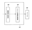
図2は、図1に示したプリンタドライバ103が行う処理を説明する図である。
FIG. 2 is a diagram illustrating processing performed by the
図2において、画像補正処理部201は、OS102から入力される描画命令群に含まれる色情報に対して画像補正処理を行う。例えば、画像入力機器のデバイス色空間(例えばRGB)の色情報を輝度・色差信号に変換して輝度信号に露出補正処理を施した後,補正後の輝度・色差信号を再び入力機器のデバイス色空間のRGB色情報に逆変換する処理を行う。
In FIG. 2, an image
プリンタ用補正処理部202は、上記のように画像補正処理された入力機器のデバイス色空間のRGB色情報を参照して、描画命令に基づき画像をラスタライズし、ページメモリ上にラスタ画像を生成する。そして、このラスタ画像に対して前段色信号変換(色再現性を保持した入力機器のデバイス色空間から出力機器のデバイス色空間への色変換)、後段色信号変換(CMYKへの色分解)および階調補正などの処理を施し、画素ごとにプリンタ105の色再現性を決定するCMYKデータを生成する。
The printer
なお、以上図2を参照して説明した処理はプリンタドライバ103が行う処理として説明したが、アプリケーションによって行うこともできる。
The processing described with reference to FIG. 2 has been described as processing performed by the
図3は、図2に示したプリンタ用補正処理部202の処理を詳細に説明する図である。
図3において、画像信号入力部301によって入力された画像データは、前段色信号処理部302における入力カラーマッチング処理、後段色信号処理部303におけるインクジェットプリンタの特性を考慮した色分解処理、および階調補正部304における階調補正およびハーフトーン処理が施され、プリンタ104で用いるシアン(C)、マゼンタ(M)、イエロー(Y)、ブラック(K)、淡シアン(c)、淡マゼンタ(m)の各インクに対応したC、M、Y、K、c、mのドットデータが生成される。そして、画像出力部305は、これらのドットデータをプリンタ104における印刷動作に応じたタイミングでプリンタ104へ転送する。以上のプリンタ用補正処理部202において、前段色信号変換部で用いるLUTは、図5、図6にて後述されるテーブル作成処理によって作成される。
FIG. 3 is a diagram for explaining in detail the processing of the printer
In FIG. 3, the image data input by the image
本実施形態では、プリンタ104として通常の濃度のインクC、M、Y、Kと、インクC、Mより濃度の低いそれぞれの淡インクc、mとの計6色のインクを用いる。後段色信号処理では、プリンタにおける、印刷したドットの粒状感や、記録媒体が単位時間、単位面積当りに受容可能な総インク液滴量を考慮した色分解を行う。後段色処理部303で用いるLUTは、これらの条件を考慮して、RGBデータを色分解して適切なC、M、Y、K、c、mのインクの組み合わせを出力するよう設定されている。このように、後段色処部303を介してプリンタの色処理を操作すれば、プリンタの構成,例えばCMYKの4色であるとか、CMYKcmの六色であるとかといった構成に左右されることなく、単にRGBデータを処理するRGBデバイスとしてプリンタを扱うことができる。このときのRGBデータを後段RGBと呼ぶことにする。具体的には、前段色信号処理部302から出力されるRGBデータが後段RGBとなっている。
In the present embodiment, the
前段色信号処理部302で用いるLUT(以下、前段色処理テーブルとも言う)は、画像入力機器のデバイス色空間(RGBの色空間)を出力機器のデバイス色空間(後段RGB)へ色変換を行うための三次元LUTである。本実施形態では、色再現特性に関して、階調性を重視した色再現性、彩度を重視した色再現性、測色的一致を重視した色再現性、記憶色を重視した色再現性それぞれに対応した前段色処理テーブルを用意し、印刷する画像などに応じて用いる前段色処理テーブルを選択する。なお、これらテーブルを、他の入力機器のデバイス色空間に対応するため、対応する色空間の数だけ前段処理テーブルを持っていてもよい。
The LUT (hereinafter also referred to as a pre-stage color processing table) used in the pre-stage color
次に、前段色処理テーブルの作成処理について説明する。 Next, a process for creating the previous color processing table will be described.
この作成処理は、先ず、作成しようとする前段色処理テーブルを構成する所定の格子点に対応した目標色を決定し、この目標色に最も近似した後段RGB値を求め、その格子点の対応色、すなわち、格子点データとする。ここで、目標色は、均等色空間である色空間Labの値として規定したものである。具体的には、作成しようとするLUTにおいて,入力RGB値で規定されるそれぞれの色(格子点)に関して,プリンタの色域外の色も含まれるため,作成する色再現性に応じて色域圧縮を行い求められた色(Lab値)を目標色とする。格子点一つ一つに対して,目標色に対応する格子点の格子点データを求めることにより,前段色処理テーブルのLUTが作成される。 In this creation process, first, a target color corresponding to a predetermined grid point constituting the previous color processing table to be created is determined, a subsequent RGB value closest to the target color is obtained, and a corresponding color of the grid point is determined. That is, the grid point data is used. Here, the target color is defined as a value of the color space Lab which is a uniform color space. Specifically, in the LUT to be created, for each color (grid point) defined by the input RGB values, colors outside the printer's color gamut are also included, so color gamut compression according to the color reproducibility to be created The color (Lab value) obtained by performing is set as the target color. The LUT of the previous color processing table is created by obtaining the grid point data of the grid point corresponding to the target color for each grid point.
さらにもう一つの方法として,目標色は、作成しようとするLUTにおいて、入力RGB値で規定されるそれぞれの色(格子点)である、例えば、ホワイト−レッド−ブラックを結ぶラインなど所定のいくつかのライン上の色(格子点)について、色再現域特性などを考慮して定める色(Lab値)である。目標色に対応する格子点の格子点データを求めると、次に、このように求めた所定の格子点の格子点データ(後段RGB値)を用い、補間演算を行うことにより他の格子点の格子点データを求め、前段色処理テーブルのLUTが作成される。 As yet another method, the target color is each color (grid point) defined by the input RGB values in the LUT to be created, for example, some predetermined colors such as a line connecting white-red-black. Is a color (Lab value) determined in consideration of the color gamut characteristics and the like. When the lattice point data of the lattice point corresponding to the target color is obtained, the lattice point data (rear stage RGB value) of the predetermined lattice point obtained in this way is then used to perform interpolation calculation of other lattice points. Lattice point data is obtained and an LUT for the previous color processing table is created.
より詳細には、先ず、後段RGBデータの適当なサンプリング間隔の所定の組み合わせでカラーパッチを印刷し、それらカラーパッチを、例えばGretag社のSpectrolinoなどの測色器によって測定する。そして、その測色結果から、後段RGB値からLab値への対応を示す色空間対応テーブルを求める。すなわち、このテーブルの格子点はRGB値によって規定され、その格子点データはLab値となる。パッチを印刷しその測色結果を用いるのは、インクジェットプリンタなどでは,インクの混色による発色の変化、記録媒体へのインクの浸透の仕方による発色の変化など、複雑かつ多岐に亘る要因が発色に関連するので、その発色特性を予測することは困難なためである。以上のように求めた色空間対応テーブルを用いた補間演算を行うことによって、任意の後段RGB値に対応するLab値を求めることができる。 More specifically, first, color patches are printed at a predetermined combination of appropriate sampling intervals of the subsequent stage RGB data, and the color patches are measured by a colorimeter such as Spectrolino manufactured by Gretag, for example. Then, from the color measurement result, a color space correspondence table indicating the correspondence from the subsequent RGB value to the Lab value is obtained. That is, the grid points in this table are defined by RGB values, and the grid point data is Lab values. Inkjet printers print patches and use the colorimetric results for color development due to complex and diverse factors such as color change due to ink color mixing and color change due to ink penetration into the recording medium. This is because it is difficult to predict the color development characteristics. By performing an interpolation operation using the color space correspondence table obtained as described above, a Lab value corresponding to an arbitrary subsequent RGB value can be obtained.
次に、作成しようとする前段色処理テーブルを構成する格子点に対応した目標色と、色空間対応テーブルによって後段RGB値に対応付けられたLab値と比較し、その色差が最小となる点として近似できる点を探す。そして、その色差を最小とするRGB値を、前段色処理テーブルを構成する格子点の対応色、すなわち、格子点データとする。以上の処理を、前段色処理テーブルを構成する所定の格子点について同様に行うことにより、前段色処理テーブルの所定の複数のラインの格子点について格子点デーを求めることができる。 Next, the target color corresponding to the grid point constituting the previous color processing table to be created is compared with the Lab value associated with the subsequent RGB value by the color space correspondence table, and the color difference is minimized. Find a point that can be approximated. Then, the RGB value that minimizes the color difference is used as the corresponding color of the grid point constituting the previous color processing table, that is, grid point data. By performing the above processing in the same manner for the predetermined grid points constituting the previous color processing table, the grid point data can be obtained for the grid points of a plurality of predetermined lines in the previous color processing table.
図4は、テーブル作成に関する比較のため特許文献1に記載のテーブル作成方法を説明する図である。なお、テーブルの格子点は3次元配列したものであるが、説明の簡略化のため2次元配列のもとして説明する。 FIG. 4 is a diagram illustrating a table creation method described in Patent Document 1 for comparison regarding table creation. The grid points of the table are arranged in a three-dimensional array, but will be described as a two-dimensional array for the sake of simplicity.
図4において、401は後段RGBからLab値への対応を規定する色空間対応テーブルを構成する格子点を示している。また、402は前段色処理カラーテーブルを構成する格子点の目標色であるLab値を示している。すなわち、図4は、色空間対応テーブルの格子点と、Lab色空間における色の位置(Lab値)の両方を同時に示している。
In FIG. 4,
特許文献1に記載のテーブル作成方法では、先ず、色空間対応テーブルを構成する格子点の中から、その格子点データであるLab値と目標色との色差が最小となる格子点を探索する(第1の探索)。そうして得られた色差最小格子点が格子点403であるとする。
In the table creation method described in Patent Document 1, first, a lattice point that minimizes the color difference between the Lab value, which is the lattice point data, and the target color is searched from among lattice points constituting the color space correspondence table ( First search). It is assumed that the minimum color difference grid point obtained in this way is the
次に、探索対象となる後段RGB値の近傍領域404を設定し、その近傍領域の後段RGB値から、それに対応するLab値と目標色との色差が最小となる近似点を探し(第2の探索)、その点(後段RGB値)を着目格子点の格子点データとする。こうして得られた対応点を405によって示す。
Next, a
ここで、後段RGBがそれぞれ0〜255で定義され、後段RGBからLab値への色空間対応テーブルを構成する格子点の数が9×9×9個の場合、上記第1の探索で、探索する格子点の数は9×9×9=729個である。また、上記第2の探索では、探索すべき近傍領域は,格子点間の中間値を含まなければならないから、格子点間距離は32であるとき格子点から距離16となる領域を探索する必要がある。従って、第2の探索で、探索すべき近傍領域は少なくとも33×33×33の範囲となる。他の例として、色空間対応テーブルを構成する格子点の数が17×17×17個の場合、第1の探索で、探索する格子点の数は17×17×17=4913個である。また、この場合、第2の探索で、探索すべき近傍領域は少なくとも17×17×17の範囲となる。 Here, when the latter stage RGB is defined by 0 to 255, and the number of grid points constituting the color space correspondence table from the latter stage RGB to the Lab value is 9 × 9 × 9, the search is performed in the first search. The number of grid points to be performed is 9 × 9 × 9 = 729. In the second search, the neighboring area to be searched must include an intermediate value between the lattice points. Therefore, when the distance between the lattice points is 32, it is necessary to search for an area having the distance 16 from the lattice point. There is. Therefore, in the second search, the neighborhood area to be searched is at least 33 × 33 × 33. As another example, when the number of grid points constituting the color space correspondence table is 17 × 17 × 17, the number of grid points searched in the first search is 17 × 17 × 17 = 4913. In this case, the neighborhood area to be searched in the second search is at least a range of 17 × 17 × 17.
図5は、本実施形態に係る前段色処理テーブルの作成処理を説明する図である。
本実施形態では、先ず、1つ目の前段色処理テーブルを予め用意しておく。すなわち、本実施形態では、前述したように、色再現特性に関して複数の前段色処理テーブルを作成する。その場合に、2つ目以降の前段色処理テーブルの作成について、本発明の一実施形態に係るテーブル作成方法を適用する。従って、1つ目の前段色処理テーブルは、特許文献1などで従来知られる方法のいずれを用いて作成してもよい。
FIG. 5 is a diagram for explaining the pre-color processing table creation process according to the present embodiment.
In this embodiment, first, a first previous color processing table is prepared in advance. That is, in the present embodiment, as described above, a plurality of pre-stage color processing tables are created regarding the color reproduction characteristics. In that case, the table creation method according to the embodiment of the present invention is applied to the creation of the second and subsequent pre-stage color processing tables. Therefore, the first previous color processing table may be created using any of the methods conventionally known in Patent Document 1 or the like.
また、図5において、401は後段RGBからLab値への関係を規定する色空間対応テーブルを構成する格子点を示す。また、402は作成しようとしている第2の前段色処理テーブルを構成する格子点の目標色であるLab値を示す。すなわち、図5は、図4と同様、色空間対応テーブルの格子点と、Lab色空間における色の位置(Lab値)の両方を同時に示している。
In FIG. 5,
先ず、予め作成された1つ目の前段色処理テーブルを利用し、2つ目の前段色処理テーブルを構成する所定の格子点について、その格子点の目標色に対応した後段RGB値501を補間計算によって求める。すなわち、処理に係る着目格子点である上記所定の格子点が1つ目の前段色処理テーブルにおいて占める位置に応じて、そのテーブルの周囲の複数の格子点それぞれの格子点データ(後段RGB値)を用いた補間演算を行い、着目格子点に対応した後段RGB値501を求める。
First, using a first pre-stage color processing table created in advance, for a predetermined grid point constituting the second pre-stage color process table, a
次に、得られた後段RGB値501に対してその近傍領域502を設定し、その近傍領域502に含まれる総ての後段RGB値から目標色にもっとも近似する後段RGB値503を、着目格子点の格子点データとして求める。
Next, the
以上の処理を所定の格子点の総てについて行って格子点データを求め、他の格子点については所定の格子点データを用いた補間演算を行うことにより、それらの格子点データを求め、2つ目の前段色処理テーブルを作成することができる。 The above processing is performed for all of the predetermined lattice points to obtain lattice point data, and for other lattice points, interpolation processing using the predetermined lattice point data is performed to obtain those lattice point data. A first previous color processing table can be created.
また、3つ目以降の前段色処理テーブルも、上記と同様に求めることができる。 Further, the third and subsequent pre-color processing tables can be obtained in the same manner as described above.
以上のとおり、2つ目以降の前段色処理テーブルを作成する本実施形態の方法では、特許文献1に記載の方法と比べて、後段RGBからLab値への色空間対応テーブルを構成する格子点での中から目標値との色差が最小となる格子点を探索する、第1の探索を実行する必要がない。これにより、色空間対応テーブルを構成する格子点の数が9×9×9個の場合、目標値1つに対して9×9×9=729個、また、格子点の数が17×17×17個の場合、17×17×17=4913個の探索をする必要がなくなり、大幅に探索時間を削減することができる。 As described above, in the method of the present embodiment for creating the second and subsequent pre-stage color processing tables, the grid points constituting the color space correspondence table from the post-stage RGB to the Lab value, compared to the method described in Patent Document 1. It is not necessary to execute the first search for searching for a lattice point having the smallest color difference from the target value from Thereby, when the number of grid points constituting the color space correspondence table is 9 × 9 × 9, 9 × 9 × 9 = 729 for one target value, and the number of grid points is 17 × 17. In the case of × 17, it is not necessary to search for 17 × 17 × 17 = 4913, and the search time can be greatly reduced.
さらに、好ましくは、1つ目の前段色処理カラーテーブルを、測色的一致を重視した色再現性を実現するテーブルとする。すなわち、このテーブルは、それを作成する際の格子点の目標値が、その格子点データである後段RGB値によって印刷したパッチの測色値に一致するように設定されるような色再現特性を持ったものである。この測色的一致を重視した色再現性を持つ前段色処理テーブルを1つ目のテーブルとして用いると、そのテーブルにおける補間処理によって、目標値に対応する格子点の格子点データに最も近い後段RGB値を直接求めることができる。ただし、補間処理による補間誤差を含むため、得られる後段RGB値は、出力機器のデバイス依存色空間から均等色色空間へのLUTを利用して求まる後段RGB値に比べ精度が落ちる。しかし、2つ目以降の前段色処理テーブルを構成する格子点に対して補間計算によって得られる後段RGB値501のLab値は、着目格子点に対応した目標色のLab値に比較的近い値であり、得られた後段RGB値501の極めて近傍に、色差最小となる信号値503が存在する可能性が高い。このように、1つ目の前段色処理テーブルに測色的一致を重視した色再現性を実現するテーブルを用いることにより、第2の探索で、探索すべき近傍範囲を小さくすることができる。その結果、特許文献1に記載の方法の場合、色空間対応テーブルを構成する格子点の数が9×9×9個で、近傍領域は33×33×33、他の例として格子点の数が17×17×17個で近傍領域は7×17×17であるが、この範囲を大幅に削減することができる。
More preferably, the first pre-stage color processing color table is a table that realizes color reproducibility with an emphasis on colorimetric matching. In other words, this table shows color reproduction characteristics such that the target value of the grid point at the time of creation is set so as to match the colorimetric value of the patch printed by the subsequent RGB value that is the grid point data. I have it. When the first-stage color processing table having color reproducibility with an emphasis on colorimetric matching is used as the first table, the second-stage RGB closest to the grid point data of the grid point corresponding to the target value is obtained by interpolation processing in the table. The value can be obtained directly. However, since the interpolation error due to the interpolation processing is included, the obtained subsequent RGB value is less accurate than the subsequent RGB value obtained using the LUT from the device-dependent color space of the output device to the uniform color space. However, the Lab value of the
図6は、本実施形態に係る前段色処理テーブルを作成する画像処理装置の機能を示すブロック図である。 FIG. 6 is a block diagram illustrating functions of the image processing apparatus that creates the previous-stage color processing table according to the present embodiment.
本実施形態の画像処理装置は、予め作成された入力機器のデバイス色空間と出力機器のデバイス色空間を関連付けた一つ目の前段色処理テーブルである第1LUTを保持する第1LUT保持部602、出力機器のデバイス色空間と均等色色空間を関連付けた色空間対応テーブルを保持する色空間対応LUT保持部603、および作成する前段色処理テーブルを構成する格子点の目標色(値)を保持する作成LUT目標値保持部601を具える。そして、LUT計算部604は、第1LUTを利用して目標色に対応する出力機器のデバイス色空間の色信号値を補間計算する。さらに、近傍領域探索部605は、補間で得られた出力機器のデバイス色空間の色信号値に対してその近傍領域の総ての色信号値から目標色にもっとも近似した出力機器のデバイス色空間の信号値を色空間対応LUTを利用して求め、前段色処理テーブル606を作成する。
The image processing apparatus according to this embodiment includes a first
(実施形態2)
上記実施形態1では、入力機器のデバイス色空間から出力機器のデバイス色空間(後段RGB)への色変換である前段色変換テーブルの作成方法について述べたが、前段色変換、後段色変換の2つの色変換を行う処理系ではなく、入力機器のデバイス色空間から出力機器のデバイス色空間(CYMK)に直接変換する色信号変換テーブルの作成方法に用いることができることは、上記実施形態の説明からも明らかである。
(Embodiment 2)
In the first embodiment, the method for creating the pre-stage color conversion table, which is color conversion from the device color space of the input device to the device color space (post-stage RGB) of the output device, has been described. It can be used in a method for creating a color signal conversion table that directly converts from the device color space of the input device to the device color space (CYMK) of the output device, instead of a processing system that performs one color conversion. Is also obvious.
(実施形態3)
上記実施形態1、2では、入力機器のデバイス色空間から出力機器のデバイス色空間(後段RGBまたはCMYK)への色変換テーブルの作成方法について述べたが、ICCプロファイルを使った色変換で用いられるデバイス非依存色空間(XYZもしくはLab)から出力機器のデバイス色空間(後段RGBまたはCMYK)への色変換テーブルの作成方法に用いることも可能である。
(Embodiment 3)
In the first and second embodiments, the method for creating a color conversion table from the device color space of the input device to the device color space of the output device (the subsequent stage RGB or CMYK) has been described, but it is used in color conversion using an ICC profile. It can also be used in a method of creating a color conversion table from a device-independent color space (XYZ or Lab) to a device color space (subsequent RGB or CMYK) of an output device.
(実施形態4)
上記実施形態1ないし3では、色変換テーブルの作成方法について述べたが、前段色信号処理部302で前段色信号を後段色信号に変換する前段色処理テーブルにおいて補間演算を行う際に、実施形態1で説明した後段RGB値を推定する方法を用いることにより、前段色信号処理部302で得られる後段色信号値の変換精度の向上を図ることができる。すなわち、上記の前段色処理テーブルを一つ目のテーブルとして用い、これと予め用意した色空間対応テーブルとも用いて、補間結果として後段RGB値を推定することができる。
(Embodiment 4)
In the first to third embodiments, the method for creating the color conversion table has been described. However, when the preceding color
(実施形態5)
上記実施形態1ないし4において、ホストコンピュータ100上で一連の処理がされると説明しているが、プリンタ104にホストコンピュータ100と同等な機能を持たせ、プリンタ104上で上述した一連の処理をすることも可能である。
(Embodiment 5)
In the first to fourth embodiments, it is described that a series of processing is performed on the
例えばプリンタ内部にホストコンピュータ100と同等な機能を設けた場合には、画像データは、デジタルカメラ等の画像入力機器からプリンタに設けたカードリーダ等の読み取り手段からメモリカードを介して読み取ったり、デジタルカメラとプリンタを有線ケーブルあるいは赤外線通信手段,無線通旬手段により接続してデジタルカメラが保持するメモリカードや内蔵のメモリから読み出すことが可能である。
For example, when a function equivalent to that of the
(実施形態6)
本発明は、他のコンピュータに処理プログラムをソフトウェアとして供給することによって実現することが可能である。その場合例えば、フロッピー(登録商標)ディスク、ハードディスク、光ディスク、光磁気ディスク、CDーROM、CDーR、磁気テープ、不揮発性のメモリカード、ROMなどの記録媒体を用いて本発明を実現する処理プログラムを供給することができる。
(Embodiment 6)
The present invention can be realized by supplying a processing program as software to another computer. In this case, for example, processing for realizing the present invention using a recording medium such as a floppy (registered trademark) disk, a hard disk, an optical disk, a magneto-optical disk, a CD-ROM, a CD-R, a magnetic tape, a nonvolatile memory card, and a ROM. A program can be supplied.
100 ホストコンピュータ
101 アプリケーション
102 OS
103 プリンタドライバ
104 プリンタ
107 HD
108 CPU
109 RAM
110 ROM
201 画像補正処理部
202 プリンタ用補正処理部
301 画像信号入力部
302 前段色信号処理部
303 後段色信号処理部
304 階調補正部
305 画像出力部
601 作成LUT目標値保持部
602 第1LUT保持部
603 色空間対応LUT保持部
604 LUT計算部
605 近傍領域探索部
606 作成LUT
100
103
108 CPU
109 RAM
110 ROM
DESCRIPTION OF
Claims (9)
予め作成された、入力色信号値を出力色信号値に変換するための第1色変換テーブルと、前記出力色信号値が持つ色空間を他の所定の色空間に変換するための色空間対応テーブルと、を用意する工程と、
当該作成に係る色変換テーブルの格子点について定められる目標色に対応した出力色信号値を、前記第1色変換テーブルにおける補間計算によって求める工程と、
該求められた出力色信号値の近傍領域を設定し、該設定した近傍領域において目標色に最も近い出力色信号値を、前記色空間対応テーブルを用いて求める工程と、
該求めた、前記目標色に最も近い出力色信号値を、前記作成に係る色変換テーブルの格子点の格子点データに設定する工程と、
を有したことを特徴とする色変換テーブル作成方法。 A method for creating a color conversion table for converting an input color signal value into an output color signal value,
A first color conversion table for converting input color signal values to output color signal values created in advance , and color space support for converting the color space of the output color signal values to another predetermined color space Preparing a table;
Obtaining an output color signal value corresponding to a target color defined for a grid point of the color conversion table according to the creation by interpolation calculation in the first color conversion table;
Setting a neighborhood region of the obtained output color signal value and obtaining an output color signal value closest to the target color in the set neighborhood region using the color space correspondence table;
Setting the obtained output color signal value closest to the target color to grid point data of grid points of the color conversion table according to the creation;
A color conversion table creation method characterized by comprising:
予め作成された、入力色信号値を出力色信号値に変換するための第1色変換テーブルと、
前記出力色信号値が持つ色空間を他の所定の色空間に変換するための色空間対応テーブルと、
当該作成に係る色変換テーブルの格子点について定められる目標色に対応した出力色信号値を、前記第1色変換テーブルにおける補間計算によって求める手段と、
該求められた出力色信号値の近傍領域を設定し、該設定した近傍領域において目標色に最も近い出力色信号値を、前記色空間対応テーブルを用いて求める手段と、
該求めた、前記目標色に最も近い出力色信号値を、前記作成に係る色変換テーブルの格子点の格子点データに設定する手段と、
を有したことを特徴とする画像処理装置。 An image processing apparatus for creating a color conversion table for converting an input color signal value into an output color signal value,
A first color conversion table created in advance for converting an input color signal value into an output color signal value;
A color space correspondence table for converting the color space of the output color signal value into another predetermined color space;
Means for obtaining an output color signal value corresponding to a target color defined for a grid point of the color conversion table according to the creation by interpolation calculation in the first color conversion table;
Means for setting a neighborhood region of the obtained output color signal value and obtaining an output color signal value closest to the target color in the set neighborhood region using the color space correspondence table;
Means for setting the obtained output color signal value closest to the target color to grid point data of grid points of the color conversion table according to the creation;
An image processing apparatus comprising:
当該作成に係る色変換テーブルの格子点について定められる目標色に対応した出力色信号値を、前記第1色変換テーブルにおける補間計算によって求める手段と、
該求められた出力色信号値の近傍領域を設定し、該設定した近傍領域において目標色に最も近い出力色信号値を、前記色空間対応テーブルを用いて求める手段と、
該求めた、前記目標色に最も近い出力色信号値を、前記作成に係る色変換テーブルの格子点の格子点データに設定する手段と、
として機能させることを特徴とするプログラム。 A program for executing a process of creating a color conversion table for converting an input color signal value into an output color signal value, for converting an input color signal value created in advance into an output color signal value An image processing apparatus comprising a first color conversion table and a color space correspondence table for converting the color space of the output color signal value into another predetermined color space;
Means for obtaining an output color signal value corresponding to a target color defined for a grid point of the color conversion table according to the creation by interpolation calculation in the first color conversion table;
Means for setting a neighborhood region of the obtained output color signal value and obtaining an output color signal value closest to the target color in the set neighborhood region using the color space correspondence table;
Means for setting the obtained output color signal value closest to the target color to grid point data of grid points of the color conversion table according to the creation;
A program characterized by functioning as
Priority Applications (2)
| Application Number | Priority Date | Filing Date | Title |
|---|---|---|---|
| JP2004229357A JP4646567B2 (en) | 2004-08-05 | 2004-08-05 | Color conversion table creation method and image processing apparatus |
| US11/195,670 US8045220B2 (en) | 2004-08-05 | 2005-08-03 | Method of creating color conversion table and image processing apparatus |
Applications Claiming Priority (1)
| Application Number | Priority Date | Filing Date | Title |
|---|---|---|---|
| JP2004229357A JP4646567B2 (en) | 2004-08-05 | 2004-08-05 | Color conversion table creation method and image processing apparatus |
Publications (3)
| Publication Number | Publication Date |
|---|---|
| JP2006048420A JP2006048420A (en) | 2006-02-16 |
| JP2006048420A5 JP2006048420A5 (en) | 2010-02-12 |
| JP4646567B2 true JP4646567B2 (en) | 2011-03-09 |
Family
ID=35757069
Family Applications (1)
| Application Number | Title | Priority Date | Filing Date |
|---|---|---|---|
| JP2004229357A Expired - Fee Related JP4646567B2 (en) | 2004-08-05 | 2004-08-05 | Color conversion table creation method and image processing apparatus |
Country Status (2)
| Country | Link |
|---|---|
| US (1) | US8045220B2 (en) |
| JP (1) | JP4646567B2 (en) |
Families Citing this family (8)
| Publication number | Priority date | Publication date | Assignee | Title |
|---|---|---|---|---|
| JP2007049494A (en) * | 2005-08-10 | 2007-02-22 | Konica Minolta Business Technologies Inc | Creation method for color transformation table, image processing apparatus, image processing method, image forming apparatus, and record medium |
| US8368977B2 (en) * | 2006-03-09 | 2013-02-05 | Xerox Corporation | Method of creating 4x4 LUTs using a source and destination ICC profile |
| JP4771538B2 (en) * | 2006-07-20 | 2011-09-14 | キヤノン株式会社 | Color conversion table generation method, color conversion table, and color conversion table generation apparatus |
| JP4811750B2 (en) * | 2007-04-27 | 2011-11-09 | 日本コンピューター・システム株式会社 | COLOR CONVERSION PROGRAM, COMPUTER-READABLE RECORDING MEDIUM CONTAINING THE SAME, AND COLOR CONVERSION DEVICE |
| JP5025323B2 (en) * | 2007-05-10 | 2012-09-12 | キヤノン株式会社 | Color processing apparatus and method |
| JP5344518B2 (en) * | 2007-06-29 | 2013-11-20 | キヤノン株式会社 | Image processing method and image processing apparatus |
| JP5538925B2 (en) | 2009-02-13 | 2014-07-02 | キヤノン株式会社 | Image processing apparatus and image processing method |
| JP5268695B2 (en) * | 2009-02-13 | 2013-08-21 | キヤノン株式会社 | Image processing method and image processing apparatus |
Citations (1)
| Publication number | Priority date | Publication date | Assignee | Title |
|---|---|---|---|---|
| JP2004221635A (en) * | 2003-01-09 | 2004-08-05 | Seiko Epson Corp | Color converter, color converting method, color converting program, and print control apparatus |
Family Cites Families (9)
| Publication number | Priority date | Publication date | Assignee | Title |
|---|---|---|---|---|
| US5428465A (en) * | 1991-08-12 | 1995-06-27 | Matsushita Electric Industrial Co., Ltd. | Method and apparatus for color conversion |
| US6068361A (en) * | 1997-10-30 | 2000-05-30 | Mantell; David A. | Method and apparatus for multiple drop error diffusion in a liquid ink printer |
| JP2002094812A (en) * | 2000-09-12 | 2002-03-29 | Canon Inc | Image-processing method and device, and record medium |
| ATE440444T1 (en) * | 2000-10-06 | 2009-09-15 | Seiko Epson Corp | IMAGE PROCESSING DEVICE, IMAGE PROCESSING METHOD, RECORDED MEDIUM AND PROGRAM |
| JP4194289B2 (en) * | 2001-04-06 | 2008-12-10 | キヤノン株式会社 | Image processing method |
| JP3841151B2 (en) * | 2001-06-28 | 2006-11-01 | セイコーエプソン株式会社 | Image processing apparatus, image processing method, program, and recording medium |
| JP4252748B2 (en) * | 2001-12-05 | 2009-04-08 | ブラザー工業株式会社 | Conversion table generation method, program, color copier |
| US7433100B2 (en) * | 2003-05-30 | 2008-10-07 | Hewlett-Packard Development Company, L.P. | Color separation based on maximum toner limits |
| US7652789B2 (en) * | 2003-11-03 | 2010-01-26 | Seiko Epson Corporation | Production of color conversion profile for printing |
-
2004
- 2004-08-05 JP JP2004229357A patent/JP4646567B2/en not_active Expired - Fee Related
-
2005
- 2005-08-03 US US11/195,670 patent/US8045220B2/en not_active Expired - Fee Related
Patent Citations (1)
| Publication number | Priority date | Publication date | Assignee | Title |
|---|---|---|---|---|
| JP2004221635A (en) * | 2003-01-09 | 2004-08-05 | Seiko Epson Corp | Color converter, color converting method, color converting program, and print control apparatus |
Also Published As
| Publication number | Publication date |
|---|---|
| US20060028665A1 (en) | 2006-02-09 |
| JP2006048420A (en) | 2006-02-16 |
| US8045220B2 (en) | 2011-10-25 |
Similar Documents
| Publication | Publication Date | Title |
|---|---|---|
| JP4771538B2 (en) | Color conversion table generation method, color conversion table, and color conversion table generation apparatus | |
| EP1814309B1 (en) | Information processing method, information processing apparatus | |
| US7312891B2 (en) | Image processing method and apparatus | |
| JP5031694B2 (en) | Image processing apparatus, image processing method, and computer-readable recording medium storing program for executing the method | |
| US8045220B2 (en) | Method of creating color conversion table and image processing apparatus | |
| JP2012253774A (en) | Color printing method and color printing system | |
| JP5023036B2 (en) | Profile generation apparatus, profile generation program, profile generation method, image processing apparatus, image processing program, and image processing method | |
| JP2004188980A (en) | Digital image printing in which reduced amount of colorant is used while maintaining sensed color | |
| JP4471021B2 (en) | Color printing control apparatus, color printing control method, and color printing control program | |
| JP2008147937A (en) | Image processor and image processing method | |
| US8139266B2 (en) | Color printing control device, color printing control method, and computer readable recording medium stored with color printing control program | |
| JP6341750B2 (en) | Image processing apparatus, image processing method, and program | |
| JP4086442B2 (en) | Color space coordinate conversion method and apparatus, color signal conversion table generation method and apparatus, and memory medium | |
| JP5606150B2 (en) | Image processing apparatus and image processing method | |
| US7679782B2 (en) | System and method for extracting grayscale data in accordance with a prescribed tolerance function | |
| JP5595341B2 (en) | Image processing apparatus, image processing method, and recording apparatus | |
| JP2003334934A (en) | Device and method for controlling forming of image, and image forming control program | |
| JP2003230020A (en) | Image processor, printer, and image processing method | |
| JP2009017473A (en) | Color gamut generation device, color gamut generation method, color gamut generation program, and color conversion unit | |
| JP4921339B2 (en) | Color processing apparatus and method | |
| JP2006211579A (en) | Color profile producing method and system | |
| JPH09270923A (en) | Picture processor and picture processing method | |
| JP2006340106A (en) | Image processing method and image processor | |
| JP2009038738A (en) | Density/lightness tone correction method, and saturation tone correction method | |
| JP2005123797A (en) | Color image processing apparatus, color image processing method, and program |
Legal Events
| Date | Code | Title | Description |
|---|---|---|---|
| A521 | Written amendment |
Free format text: JAPANESE INTERMEDIATE CODE: A523 Effective date: 20070806 |
|
| A621 | Written request for application examination |
Free format text: JAPANESE INTERMEDIATE CODE: A621 Effective date: 20070806 |
|
| A521 | Written amendment |
Free format text: JAPANESE INTERMEDIATE CODE: A523 Effective date: 20091216 |
|
| A977 | Report on retrieval |
Free format text: JAPANESE INTERMEDIATE CODE: A971007 Effective date: 20100526 |
|
| A131 | Notification of reasons for refusal |
Free format text: JAPANESE INTERMEDIATE CODE: A131 Effective date: 20100604 |
|
| A131 | Notification of reasons for refusal |
Free format text: JAPANESE INTERMEDIATE CODE: A131 Effective date: 20100831 |
|
| A521 | Written amendment |
Free format text: JAPANESE INTERMEDIATE CODE: A523 Effective date: 20101101 |
|
| RD02 | Notification of acceptance of power of attorney |
Free format text: JAPANESE INTERMEDIATE CODE: A7422 Effective date: 20101106 |
|
| TRDD | Decision of grant or rejection written | ||
| A01 | Written decision to grant a patent or to grant a registration (utility model) |
Free format text: JAPANESE INTERMEDIATE CODE: A01 Effective date: 20101203 |
|
| A01 | Written decision to grant a patent or to grant a registration (utility model) |
Free format text: JAPANESE INTERMEDIATE CODE: A01 |
|
| A61 | First payment of annual fees (during grant procedure) |
Free format text: JAPANESE INTERMEDIATE CODE: A61 Effective date: 20101207 |
|
| FPAY | Renewal fee payment (event date is renewal date of database) |
Free format text: PAYMENT UNTIL: 20131217 Year of fee payment: 3 |
|
| R150 | Certificate of patent or registration of utility model |
Free format text: JAPANESE INTERMEDIATE CODE: R150 |
|
| LAPS | Cancellation because of no payment of annual fees |