JP4644872B2 - Folding glue transfer machine - Google Patents
Folding glue transfer machine Download PDFInfo
- Publication number
- JP4644872B2 JP4644872B2 JP2008131344A JP2008131344A JP4644872B2 JP 4644872 B2 JP4644872 B2 JP 4644872B2 JP 2008131344 A JP2008131344 A JP 2008131344A JP 2008131344 A JP2008131344 A JP 2008131344A JP 4644872 B2 JP4644872 B2 JP 4644872B2
- Authority
- JP
- Japan
- Prior art keywords
- drive shaft
- longitudinal
- conveying
- conveying device
- support structures
- Prior art date
- Legal status (The legal status is an assumption and is not a legal conclusion. Google has not performed a legal analysis and makes no representation as to the accuracy of the status listed.)
- Active
Links
- 239000003292 glue Substances 0.000 title claims description 4
- 239000000463 material Substances 0.000 claims description 14
- 230000001681 protective effect Effects 0.000 claims description 5
- 238000006073 displacement reaction Methods 0.000 abstract 2
- 239000011087 paperboard Substances 0.000 description 11
- 238000004026 adhesive bonding Methods 0.000 description 7
- 238000004519 manufacturing process Methods 0.000 description 4
- 230000000295 complement effect Effects 0.000 description 3
- 230000000694 effects Effects 0.000 description 3
- 230000008901 benefit Effects 0.000 description 2
- 239000011111 cardboard Substances 0.000 description 2
- 238000003825 pressing Methods 0.000 description 2
- 238000013459 approach Methods 0.000 description 1
- 238000005452 bending Methods 0.000 description 1
- 230000008859 change Effects 0.000 description 1
- 239000000428 dust Substances 0.000 description 1
- 230000003993 interaction Effects 0.000 description 1
- 239000002184 metal Substances 0.000 description 1
- 238000000034 method Methods 0.000 description 1
- 238000012986 modification Methods 0.000 description 1
- 230000004048 modification Effects 0.000 description 1
- 239000005022 packaging material Substances 0.000 description 1
- 230000002265 prevention Effects 0.000 description 1
- 230000008569 process Effects 0.000 description 1
- 239000002356 single layer Substances 0.000 description 1
- 238000004513 sizing Methods 0.000 description 1
- 238000011144 upstream manufacturing Methods 0.000 description 1
Images

Classifications
-
- B—PERFORMING OPERATIONS; TRANSPORTING
- B65—CONVEYING; PACKING; STORING; HANDLING THIN OR FILAMENTARY MATERIAL
- B65H—HANDLING THIN OR FILAMENTARY MATERIAL, e.g. SHEETS, WEBS, CABLES
- B65H5/00—Feeding articles separated from piles; Feeding articles to machines
- B65H5/02—Feeding articles separated from piles; Feeding articles to machines by belts or chains, e.g. between belts or chains
- B65H5/021—Feeding articles separated from piles; Feeding articles to machines by belts or chains, e.g. between belts or chains by belts
- B65H5/023—Feeding articles separated from piles; Feeding articles to machines by belts or chains, e.g. between belts or chains by belts between a pair of belts forming a transport nip
-
- B—PERFORMING OPERATIONS; TRANSPORTING
- B65—CONVEYING; PACKING; STORING; HANDLING THIN OR FILAMENTARY MATERIAL
- B65H—HANDLING THIN OR FILAMENTARY MATERIAL, e.g. SHEETS, WEBS, CABLES
- B65H2403/00—Power transmission; Driving means
- B65H2403/50—Driving mechanisms
- B65H2403/52—Translation screw-thread mechanisms
-
- B—PERFORMING OPERATIONS; TRANSPORTING
- B65—CONVEYING; PACKING; STORING; HANDLING THIN OR FILAMENTARY MATERIAL
- B65H—HANDLING THIN OR FILAMENTARY MATERIAL, e.g. SHEETS, WEBS, CABLES
- B65H2407/00—Means not provided for in groups B65H2220/00 – B65H2406/00 specially adapted for particular purposes
- B65H2407/10—Safety means, e.g. for preventing injuries or illegal operations
-
- B—PERFORMING OPERATIONS; TRANSPORTING
- B65—CONVEYING; PACKING; STORING; HANDLING THIN OR FILAMENTARY MATERIAL
- B65H—HANDLING THIN OR FILAMENTARY MATERIAL, e.g. SHEETS, WEBS, CABLES
- B65H2511/00—Dimensions; Position; Numbers; Identification; Occurrences
- B65H2511/10—Size; Dimensions
-
- B—PERFORMING OPERATIONS; TRANSPORTING
- B65—CONVEYING; PACKING; STORING; HANDLING THIN OR FILAMENTARY MATERIAL
- B65H—HANDLING THIN OR FILAMENTARY MATERIAL, e.g. SHEETS, WEBS, CABLES
- B65H2511/00—Dimensions; Position; Numbers; Identification; Occurrences
- B65H2511/20—Location in space
-
- B—PERFORMING OPERATIONS; TRANSPORTING
- B65—CONVEYING; PACKING; STORING; HANDLING THIN OR FILAMENTARY MATERIAL
- B65H—HANDLING THIN OR FILAMENTARY MATERIAL, e.g. SHEETS, WEBS, CABLES
- B65H2701/00—Handled material; Storage means
- B65H2701/10—Handled articles or webs
- B65H2701/17—Nature of material
- B65H2701/176—Cardboard
- B65H2701/1764—Cut-out, single-layer, e.g. flat blanks for boxes
-
- B—PERFORMING OPERATIONS; TRANSPORTING
- B65—CONVEYING; PACKING; STORING; HANDLING THIN OR FILAMENTARY MATERIAL
- B65H—HANDLING THIN OR FILAMENTARY MATERIAL, e.g. SHEETS, WEBS, CABLES
- B65H2801/00—Application field
- B65H2801/81—Packaging machines
Abstract
Description
本発明の課題は、紙製またはダンボール製の低比質量のシート材を、ダンボール箱などを成形する梱包材産業で広く使用されている機械である折畳み糊付け装置(製函用の折畳み糊付け装置)に搬入する搬送装置である。 An object of the present invention is a folding gluing device (folding gluing device for box making), which is a machine widely used in the packaging material industry for forming cardboard boxes and the like with a sheet material made of paper or cardboard and having a low specific mass. It is the conveying apparatus carried in.
従来、折畳み糊付け装置は一連のモジュールおよびステーションを有しており、その個数は、選択された種類の箱を製造するのに必然的に要する作業の複雑さ次第で変動する。このような機械は、大抵、スタックから板紙材を1枚ずつ製函ラインに供給するシート給送装置と、整列用モジュールと、90度から180度までの間で第1折目と第3折目を予備的に折るブレーカーと、板紙材の正面フラップを180度折込んでから背面フラップを180度折込む折込フックモジュールと、糊付ステーションと、板紙材の第2折目および第4折目を折る折込装置と、第2折目および第4折目を圧迫して複数の箱を均して1層にするプレス機と、最終工程段で、複数の箱を受け入れて、きつく押しをかけた状態に保ち、糊を乾かすことができるようにする受け入れモジュールとを含んでいる。板紙材は、ベルト型コンベアーを使って1つのステーションから次のステーションに搬送されるが、このようなコンベアーは摩擦により下部コンベアーと上部コンベアーの間に板紙材を把持する。従来、下部コンベアーは底面ベルトを装備しており、上部コンベアーは上部ベルトまたは上部プレスローラーを装備している。 Traditionally, a folding gluing device has a series of modules and stations, the number of which varies depending on the complexity of the operations necessary to produce a selected type of box. Such machines usually have a sheet feeding device that supplies paperboard materials from the stack one by one to the box making line, an alignment module, and the first and third folds between 90 and 180 degrees. Breaker for pre-folding the eye, Folding hook module that folds the front flap of paperboard 180 degrees and then the back flap 180 degrees, Gluing station, 2nd and 4th folds of paperboard Folding device, press machine that squeezes the second and fourth folds to level multiple boxes into a single layer, and accepts multiple boxes at the final process stage and presses tightly And a receiving module that allows the glue to be kept dry. The paperboard material is transported from one station to the next using a belt-type conveyor. Such a conveyor grips the paperboard material between the lower conveyor and the upper conveyor by friction. Conventionally, the lower conveyor is equipped with a bottom belt and the upper conveyor is equipped with an upper belt or an upper press roller.
下部コンベアーは2本以上の長手方向部材を備えており、これら長手方向部材は各々がプーリーおよびローラーによって支持されたエンドレスコンベアーベルトを支えている。長手方向部材は各々に、1個以上の移動用滑走部材に沿ってベアリングを介して横滑り自在な滑動部材が搭載されており、滑走部材は2本の長手方向に延びている支持構造体の間に固着されている。長手方向部材の横断方向位置を加工処理に付される板紙材の形式に適合させる目的で、長手方向部材は各々が1本以上の互いに平行なネジによって横断方向に移動させられるが、これらネジのネジを切った部分は、長手方向部材の一部である、それぞれ雌ネジ立てた横断方向の開口部にねじ込まれて、ネジが支持構造体の間で回転することができるように取付けられている。 The lower conveyor is provided with two or more longitudinal members, each supporting an endless conveyor belt supported by pulleys and rollers. Each longitudinal member is mounted with a sliding member slidable through a bearing along one or more moving sliding members, the sliding member between two longitudinally extending support structures. It is fixed to. For the purpose of adapting the transverse position of the longitudinal members to the type of paperboard subjected to processing, the longitudinal members are each moved transversely by one or more parallel screws, The threaded part is screwed into a transverse opening, each of which is part of the longitudinal member, and is mounted so that the screw can rotate between the support structures. .
支持構造体相互の間で回転自在に取付けられた駆動シャフトによって、個々の長手方向部材ごとに、エンドレスコンベアーベルトが駆動され、長手方向部材の一部であるプーリーと係合状態となっているが、このプーリーは駆動プーリーと呼ばれる。駆動シャフトは、駆動ラインによって電気モーターに接続されているため、モーターが回転すると回動させられる。 The endless conveyor belt is driven for each individual longitudinal member by a drive shaft that is rotatably mounted between the support structures and is engaged with a pulley that is part of the longitudinal member. This pulley is called the drive pulley. Since the drive shaft is connected to the electric motor by a drive line, the drive shaft is rotated when the motor rotates.
一般に、駆動シャフトは六角形などの多角形の金属棒の形状を呈しており、形状に関しては駆動プーリーの軸線に沿って形成されている横断方向の開口部と相補し合う断面形状になっている。従って、長手方向部材は、調節用ネジの動作によって横断方向に移動する場合には、移動用滑走部材に沿って滑動するとともに、駆動シャフトに沿っても滑動する。 In general, the drive shaft has a shape of a polygonal metal rod such as a hexagon, and has a cross-sectional shape that is complementary to a transverse opening formed along the axis of the drive pulley. . Therefore, when the longitudinal member moves in the transverse direction by the operation of the adjusting screw, it slides along the sliding member for movement and also slides along the drive shaft.
本発明の機械によって板紙材を操作するのに必要であるとともに駆動するのに必要となる動力は、機械の幅で決まることに注目するべきである。その結果、機械の幅が広いほど、伝達されなければならない力は大きくなるが、これは、シャフトの捻り力が、例えば、シャフトの断面を増大するといった手段によって高められる必要があることを意味している。従って、長手方向部材の重量が移動用滑走部材によって支えられているせいで、駆動シャフトは捻り耐性を有するようにさえ設計されていればよいが、実際には、機械の或る部分に接近するのに、機械の操作者は躊躇せずに駆動シャフトによじ登ることがあるのが分かる。このため、駆動シャフトが折れ曲がるのを防ぐために、この駆動シャフトは反れを起こさずに人の体重に耐えるようにも設計されねばならず、従って、シャフトの製造経費が高くつく。 It should be noted that the power required to operate and drive the paperboard material by the machine of the present invention is determined by the width of the machine. As a result, the wider the machine, the greater the force that must be transmitted, which means that the twisting force of the shaft needs to be increased by means such as increasing the cross-section of the shaft. ing. Thus, the drive shaft need only be designed to be torsionally resistant because the weight of the longitudinal member is supported by the moving sliding member, but in practice it approaches some part of the machine. However, it can be seen that the machine operator may climb on the drive shaft without hesitation. For this reason, in order to prevent the drive shaft from bending, the drive shaft must be designed to withstand a person's weight without causing warping, and therefore the manufacturing cost of the shaft is high.
更に、安全性の見地から、機械の操作者に対して剥き出しになっている駆動シャフトがスリーブの内部に嵌合させられる。スリーブは、大抵、渦巻きバネの形状を呈しており、このバネの一方端は支持構造体に固着されており、残りの一方端は長手方向部材に固着されており、長手方向部材の横断方向の運動がバネを伸縮させる。容易に分かることであるが、このようなバネの存在により、これに応じて長手方向部材を駆動する主ネジの寸法を設定しなければならない。この理由は、渦巻きバネの硬度が高いほど、長手方向部材を移動させることができるようにするために強いトルクがネジに及ぼされなければならないからであり、これでまた必然的に、ネジを回転させるモーターの電動力をこれに応じて適合させなければならなくなる。 Furthermore, from a safety standpoint, a drive shaft that is exposed to the machine operator is fitted into the sleeve. The sleeve is typically in the form of a spiral spring, one end of which is secured to the support structure and the other end is secured to the longitudinal member, which is transverse to the longitudinal member. The movement expands and contracts the spring. As will be readily appreciated, the presence of such a spring requires that the dimensions of the main screw that drives the longitudinal member be set accordingly. The reason for this is that the higher the hardness of the spiral spring, the stronger the torque that must be exerted on the screw in order to be able to move the longitudinal member, and this also necessarily rotates the screw. The electric power of the motor to be adjusted must be adapted accordingly.
本発明の1つの目的は、駆動シャフトに反れ防止をする必要がなく、尚且つ、保護用のスリーブも必要ではない搬送装置を提示することにより、上述の課題を解決することである。 One object of the present invention is to solve the above-mentioned problems by presenting a transport device that does not require warpage prevention of the drive shaft and that does not require a protective sleeve.
上記目的で、本発明の主題は請求項1に記載の搬送装置である。 For this purpose, the subject of the present invention is a transport device according to claim 1.
本発明の効果により、駆動シャフトは捻り力のみに耐えるよう設計されており、従って、シャフトの寸法を減じることができ、よって、シャフトの質量を相当に減じることができる。その結果、シャフトを製造するのに要する材料が少なくて済み、シャフトの製造経費および寸法を減じることができる。 By virtue of the effects of the present invention, the drive shaft is designed to withstand only torsional forces, so that the shaft dimensions can be reduced and thus the shaft mass can be reduced considerably. As a result, less material is required to manufacture the shaft, and the manufacturing costs and dimensions of the shaft can be reduced.
これに加えて、本発明の効果により、駆動シャフトは機械操作者に対して剥き出しとなっておらず、すなわち、先行技術の保護用スリーブは省くことができる。その結果、ネジの寸法と、ネジを回転させるための電気モーターの寸法とを低減することができる。 In addition, due to the effect of the present invention, the drive shaft is not exposed to the machine operator, i.e. the prior art protective sleeve can be omitted. As a result, the size of the screw and the size of the electric motor for rotating the screw can be reduced.
本発明のまた別な利点は、機械がより容易に使えるようにするとともに、各構成部材の寿命を延ばすことである。実際に、本発明の効果により、駆動シャフト、主ネジ、および、移動用滑走部材は、本発明による搬送装置が糊付ステーションに置かれた場合に、埃または糊などがどんな態様であれ堆積し、または、飛散することから保護されている。 Another advantage of the present invention is that it makes the machine easier to use and extends the life of each component. In fact, due to the effect of the present invention, the drive shaft, the main screw, and the moving sliding member are deposited in any manner such as dust or glue when the conveying device according to the present invention is placed in the gluing station. , Or protected from splashing.
本件の開示内容は下部コンベアーを例示しているが、好ましい実施形態において記載されている下部コンベアーと同じ各種機能部および構成部材を備えている上部コンベアーについても同様に利用することできる。 Although the disclosure of the present example exemplifies a lower conveyor, the present invention can be similarly used for an upper conveyor having the same various functional units and components as those of the lower conveyor described in the preferred embodiment.
本発明のまた別な目的および利点は、添付の図面を参照しながら理解されれば実施形態の詳細な説明により一層はっきり分かるようになる。 Further objects and advantages of the present invention will become more apparent from the detailed description of the embodiments when understood with reference to the accompanying drawings.
後段の詳細な説明に導入されている用語で、製函用折畳み糊付け装置の内部における或る構成要素の位置を説明する用語のうち幾つかを定義するために、「操作者側の端部」および「非操作者側の端部」という語について言うと、これらの語は機械の長手方向の中心軸線に関して指定されている一端部のことを述べるために使用されるという点で疑いの余地はない。このように語を選択することで、観察者の視点で決まる通常の左右識別表示から生じる恐れのある混乱を回避することができる。同じような理由から、或る運動の向きおよび或る構成部材の配向も、シート材が移動する向きによって方向が決まる機械の中心軸線についての言及である「長手方向」および「横断方向」という通例の用語を使って説明することになる。最後に、「上流」および「下流」という語それら自体は、(製函用)折畳み糊付け装置の中を通ってシート材が移動する方向について述べたものであるということも、強調しておかなければならない。 In order to define some of the terms that are introduced in the detailed description below and that describe the location of certain components within the folding sizing device for box making, the “end on the operator side” And with respect to the term "non-operator end", there is no doubt that these terms are used to describe the end that is specified with respect to the machine's longitudinal central axis. Absent. By selecting the words in this way, it is possible to avoid confusion that may arise from the normal left / right identification display determined by the observer's viewpoint. For similar reasons, the direction of movement and the orientation of certain components are also commonly referred to as “longitudinal” and “transverse”, which refers to the central axis of the machine whose direction is determined by the direction in which the sheet material moves. It will be explained using the terminology. Finally, it should also be emphasized that the words “upstream” and “downstream” themselves describe the direction in which the sheet material moves through the folding gluing device (for box making). I must.
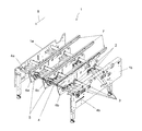
図1は、先行技術による下部コンベアー1を例示している。矢印8はシート材の移動方向を示している。このようなコンベアーは、大抵、2本の長手方向に延びている支持構造体1a、1bを備えており、これら構造体は互いに平行で、互いから離隔されている。支持構造体は各々が2つの主要面、すなわち、内側面と外側面を有しており、一方の支持構造体の内側面は他方の支持構造体の内側面に対面している。この実施形態では、支持構造体1aは非操作者側の端部に位置しており、支持構造体1bは操作者側の端部に位置している。これら2本の支持構造体1a、1bの間には、横断方向に位置決めされた2本の互いに平行な円筒状の移動用滑走部材2と、3対の互いに平行な主ネジ3と、駆動シャフト4が存在する。移動用滑走部材2は支持構造体1a、1bにそれぞれの端部の位置で組付けられて、3本の互いに平行な長手方向部材6a、6b、6cを支持する意図で設けられているが、これら長手方向部材は横並びに取付けられているとともに、各々がエンドレスコンベアーベルト7を支持しており、エンドレスコンベアーベルトは硬質の水平面に載置され、特に一連のローラーの上に載置されるのが好ましい(ローラーは図示せず)。長手方向部材は各々が、処理するべき板紙材の形式に従って、移動用滑走部材2に沿って支持構造体1aと支持構造体1bの間で横断方向に移動させることができる。
FIG. 1 illustrates a lower conveyor 1 according to the prior art. An arrow 8 indicates the moving direction of the sheet material. Such conveyors are usually provided with two longitudinally extending
コンベアーベルト7に対して板紙材を押圧するための装置(図示せず)が長手方向部材6a、6b、6cの或る部分より上位に設置されている。これら押圧部材はバネによって下方に維持された一連のローラーから構成されているか、または、底面連続部が下方向に押し下げられたエンドレスベルトから構成されているようにするとよい。
A device (not shown) for pressing the paperboard material against the conveyor belt 7 is installed above a certain part of the
長手方向部材6a、6b、6cは、横断方向位置を変動させるために、主ネジ3に斜歯接続状態で取付けられている。詳細に説明すると、長手方向部材は各々が、横断方向の移動を1対の互いに平行なネジ3によって制御されており、これら主ネジのネジを切った部分が長手方向部材の一部であるそれぞれの横断方向の雌ネジを立てた開口部の中に嵌合し、このような主ネジは並進運動しないようにされているが、支持構造体1aと支持構造体1bの間で自由に回転することができる。1個以上の電気モーター(図示せず)がネジ3を回転させるために設けられている。
The
エンドレスコンベアーベルト7は各々がローラーおよび駆動プーリー5によって支持されている。駆動プーリー5は互いに同軸であるとともに、それぞれの長手方向部材に回転自在に取付けられている。コンベアーベルト7を駆動するために、駆動シャフト4は支持構造体1aと支持構造体1bとの間で回転するように取付けられており、駆動プーリー5に嵌合させられている。この実施形態では、シャフト4は形状に関しては駆動プーリー5の各々の軸線に沿って形成されている横断方向の開口部と相補し合う断面形状になっている。従って、長手方向部材6a、6b、6cは、1対の調節用ネジ3の動作によって横断方向に移動する場合には、移動用滑走部材2に沿って滑動するとともに、駆動シャフト4に沿っても滑動する
Each endless conveyor belt 7 is supported by a roller and a
安全上の理由から、機械操作者に対して剥き出しになっている駆動シャフト4の各部は2つのスリーブ4a、4bの中に嵌合させられている。スリーブ4a、4bは各々が、シャフト両端部の位置に組込まれた渦巻きバネの形状を呈している。非操作者側の端部を覆うスリーブは、参照番号4aで示されているが、一方端が支持構造体1aに固着されており、他方端は長手方向部材6a、すなわち、支持構造体1aに最も近接した長手方向部材に固着されている。操作者側の端部のスリーブは、参照番号4bと示されており、一方端が支持構造体1bに固着されており、他方端は長手方向部材6b、すなわち、支持構造体1bに最も近接した長手方向部材に固着されている。従って、電気モーター(図示せず)の作動によってシャフト4が回動させられている場合、スリーブ4a、4bは、非操作者側の端部と操作者側の端部の両方で、機械操作者と駆動シャフト4の間の直接接触は如何なるものであれ阻止する。
For safety reasons, each part of the drive shaft 4 which is exposed to the machine operator is fitted in two
それぞれの長手方向部材6a、6bの横断方向運動がそれぞれのバネ4a、4bを伸縮させる点が注目に値し、また、シャフト6は長手方向部材6aと長手方向部材6bの間で保護状態にない点にも留意するべきである。
It is noteworthy that the transverse movement of each
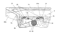
図2および図3は、本発明による下部コンベアー10を例示している。矢印8は、シート材が移動する方向を示している。このコンベアーは2本の支持構造体10a、10bを備えており、支持構造体は互いに平行であるとともに、互いから離隔されている。支持構造体10aと支持構造体10bとの間には、2本の長手方向部材60a、60bが存在する。長手方向部材60a、60bは各々が、U字型断面形状部9に固着されている1対の移動用滑走部材20を共用して滑動自在な接続状態で取付けられている。U字型断面形状部9は2本の支持構造体10a、10bの間で横断方向に延びており、このU字型断面形状部9の両端部は支持構造体10a、10bの中に組付けられている。この実施形態では、U字型断面形状部9の桁腹部(ウェブ)9aは水平面であるが、突縁部9b、9cは垂直面であって機械の底面に向けて延びている。1対の移動用滑走部材20はU字型断面形状部9のU字の内側で桁腹部9aに取付けられて、2本の支持構造体10a、10bの間で横断方向に延びている。移動用滑走部材20は各々が直線状のガイドレールであり、その断面は両凹状で、第1凹面は機械の正面を向き、第2凹面は機械の背面を向いている(図3を参照のこと)。
2 and 3 illustrate a
長手方向部材60aには開口部61aが、長手方向部材60bには開口部61bが設けられており、これら開口部の形状はU字型で、この中をU字型断面形状部9が通っているが何らの相互作用もしない。長手方向部材60a、60bを横断方向に案内するために、長手方向部材は各々に1対の滑走溝21が装備されており、これら滑走溝は移動用滑走部材と相補し合う形状になっている。実際に、滑走溝21は各々が長手方向部材60a、60bの一部であり、その断面形状はU字型で、1つの水平面の桁腹部が設けられているとともに、2つの垂直面の突縁部が機械の最上位部に向けて延びており、突縁部の各々は、滑走溝のU字部の内部に向かって凸面が延びている断面形状であり、滑走部21の凸面が移動用滑走部材20の凹面と相補協働して、滑動自在な接続部を形成している。
The
長手方向部材60a、60bは各々が複数のローラー(図示せず)を支持しており、これらローラーの一部が、エンドレスコンベアーベルト70を案内するための硬質の水平面71の輪郭を画定している。ベルト70は駆動プーリー50によって駆動されるが、この駆動プーリーは断面形状が六角形である駆動シャフト40によって回動させられる。プーリー50は各々が駆動シャフト40と滑動自在な接続状態で取付けられている。駆動シャフト40は2本の支持構造体10a、10bの間で横断方向に延びており、シャフト40の両端はそれぞれが支持構造体10a、10bの中で自由に回動するように取付けられている。シャフト40の両端部41のうちの一方は支持構造体10aの中を通って電気モーター(図示せず)に取付けられている。
Each
本発明によれば、シャフト40はその少なくとも一部が、U字型断面形状部9の桁腹部9aより下方の突縁部9bと突縁部9cの間に設置される。この構成のおかげで、駆動シャフト40は、先行技術におけるのと同様に、もはや外側から視認できなくなり、よって、長手方向部材60a、60bの間に居る場合でさえ、機械操作者がシャフト40の影響を受けることは無くなるが、それは、シャフトがその全長に亘って保護されているからである。その結果、従来の保護用スリーブは必要ではなくなる。それに加えて、U字型断面形状部9は反れを生じることなく機械操作者の体重を支えるように設計されているため、シャフト40は、先行技術の構造の重量よりも軽量の構造となる。実際に、所与の幅の機械については、駆動シャフトの断面を少なくとも30%だけ低減することができ、従って、シャフトの製造経費と寸法を低減することができる。
According to the present invention, at least a part of the
ベルト70を硬質の水平面71に向けて帰還させるために、このベルトは、プーリー50を離れるにつれて下降させられ、移動経路のこの部分でU字型断面形状部9、および、ベルト70を案内する複数のローラー(図示せず)より下を通過するようになっている。
In order to return the
更に、移動用滑走部材20に沿って長手方向部材60a、60bを移動させるのに、1対の互いに平行な主ネジ30が設けられている。ネジ30は各々、そのネジを切った部分が長手方向部材の一部である雌ネジを立てた横断方向開口部と、ねじで嵌合し、ネジ30と長手方向部材との間で螺旋の接続部を形成し、ネジは各々が並進運動するのを阻止されて、尚且つ、支持構造体1aと支持構造体1bの間で自由に回動するように図っている。ネジ30を回転させるために、1個以上の電気モーター(図示せず)が存在する。
In addition, a pair of parallel
主ネジ30は少なくとも一部が、U字型断面形状部9の桁腹部9aより下位で突縁部9bと突縁部9cの間に設置されているのが有利である。
It is advantageous that at least a part of the
製函用折畳み糊付け装置においては、下部搬送装置は、その上に、上部コンベアーのベルトと下部コンベアーのベルトの間に挟まれた板紙材を搬送するのを、より容易にするベルト型上部コンベアーが載置されているのが一般的である。更に、本発明は上部コンベアーに適用するのが有利である。 In the folding gluing device for box making, the lower conveying device has a belt-type upper conveyor which makes it easier to convey the paperboard material sandwiched between the belt of the upper conveyor and the belt of the lower conveyor. It is generally placed. Furthermore, the present invention is advantageously applied to the upper conveyor.
本発明を特定の実施形態と関連付けて説明してきたが、上記以外の多数の変形例および修正例、ならびに、上記以外の複数の用途が当業者には自明である。よって、本発明の本件の特定の開示内容に限定されず、添付の特許請求の範囲によってのみ限定されるものと解釈するのが好ましい。 While the invention has been described in connection with specific embodiments, many variations and modifications other than those described above and multiple uses other than those described above will be apparent to those skilled in the art. Accordingly, it is not to be construed as limited to the particular disclosure of the subject matter of the invention, but is to be construed as limited only by the appended claims.
Claims (13)
前記搬送装置は2本の支持構造体(10a、10b)を備えており、支持構造体は長手方向に延びて、横断方向に互いから離隔されており、支持構造体(10a、10b)相互の間には、少なくとも1本の移動用滑走部材(20)が延びており、
前記搬送装置は、少なくとも1本の長手方向部材(60a、60b)を更に備えており、長手方向部材は前記支持構造体(10a、10b)の間に配置されており、少なくとも1本のエンドレスコンベアーベルト(70)が前記長手方向部材(60a、60b)の各々に沿って移動するように支持されており、
前記搬送装置は駆動シャフト(40)を更に備えており、駆動シャフトはエンドレスコンベアーベルト(70)を駆動してシート材を搬送するように作動し、
少なくとも1本の前記長手方向部材(60a、60b)は少なくとも1本の前記移動用滑走部材(20)の上に滑動自在な接続状態で取付けられて、前記支持構造体(10a、10b)相互の間を前記移動用滑走部材(20)に沿って移動させられるとともに、前記駆動シャフト(40)に沿って移動させられ、
前記搬送装置は少なくとも1本の主ネジ(30)を更に備えており、少なくとも1本の主ネジは前記支持構造体(10a、10b)相互の間に延びており、少なくとも1本の前記長手方向部材(60a、60b)は、少なくとも1本の前記主ネジ(30)に螺旋の接続状態で取付けられて、前記支持構造体(10a、10b)相互の間で前記長手方向部材(60a、60b)の各々を移動させ、
前記搬送装置は保護装置を更に備えており、前記保護装置は、使用者が前記駆動シャフト(40)に接近するのを阻止する形状に設定されているとともに、2本の長手方向の延びる前記支持構造体(10a、10b)を横断方向に接続する形状に設定されていることを特徴とする搬送装置。 A conveying device for carrying the sheet material into the folding glue device,
The transport device comprises two support structures (10a, 10b) that extend in the longitudinal direction and are spaced apart from each other in the transverse direction. In between, at least one moving sliding member (20) extends,
The conveying device further comprises at least one longitudinal member (60a, 60b), the longitudinal member being disposed between the support structures (10a, 10b), and at least one endless conveyor. A belt (70) is supported to move along each of the longitudinal members (60a, 60b);
The transport device further comprises a drive shaft (40), the drive shaft operates to drive the endless conveyor belt (70) to transport the sheet material;
At least one of the longitudinal members (60a, 60b) is slidably connected on at least one of the moving sliding members (20) so that the support structures (10a, 10b) are connected to each other. Moved along the sliding member for movement (20) and moved along the drive shaft (40),
The conveying device further comprises at least one main screw (30), the at least one main screw extending between the support structures (10a, 10b), and at least one longitudinal direction. A member (60a, 60b) is attached to at least one of the main screws (30) in a spiral connection, and the longitudinal members (60a, 60b) between the support structures (10a, 10b). Move each of the
The transport device further comprises a protection device, the protection device being configured to prevent a user from approaching the drive shaft (40) and having two longitudinally extending supports. A conveying device characterized in that the structure (10a, 10b) is set in a shape for connecting in the transverse direction.
Applications Claiming Priority (1)
| Application Number | Priority Date | Filing Date | Title |
|---|---|---|---|
| EP07007749 | 2007-04-17 |
Publications (2)
| Publication Number | Publication Date |
|---|---|
| JP2008265345A JP2008265345A (en) | 2008-11-06 |
| JP4644872B2 true JP4644872B2 (en) | 2011-03-09 |
Family
ID=38542133
Family Applications (1)
| Application Number | Title | Priority Date | Filing Date |
|---|---|---|---|
| JP2008131344A Active JP4644872B2 (en) | 2007-04-17 | 2008-04-17 | Folding glue transfer machine |
Country Status (8)
| Country | Link |
|---|---|
| US (1) | US7810812B2 (en) |
| EP (1) | EP1982937B1 (en) |
| JP (1) | JP4644872B2 (en) |
| CN (1) | CN101289015B (en) |
| AT (1) | ATE452845T1 (en) |
| DE (1) | DE602008000430D1 (en) |
| ES (1) | ES2337420T3 (en) |
| TW (1) | TWI357880B (en) |
Families Citing this family (5)
| Publication number | Priority date | Publication date | Assignee | Title |
|---|---|---|---|---|
| JP6054515B2 (en) * | 2012-04-23 | 2016-12-27 | ボブスト メックス ソシエテ アノニム | Module including frame and folder / gluer equipped with the same |
| CN104325686B (en) * | 2014-10-19 | 2019-04-23 | 广东鸿铭智能股份有限公司 | Paper feeding positioning guide mechanism |
| ES2610033B1 (en) * | 2015-09-22 | 2018-01-30 | Biele, S.A. | UNIVERSAL AUTOMATED STACKING DEVICE |
| CN105666940B (en) * | 2016-04-11 | 2018-05-04 | 杭州禾康包装材料有限公司 | A kind of paper feeding spool driving device of automatic paper feeder |
| CN115042479B (en) * | 2022-06-30 | 2023-11-17 | 温州永邦机械有限公司 | Tile mounting machine with vacuum adsorption function |
Citations (3)
| Publication number | Priority date | Publication date | Assignee | Title |
|---|---|---|---|---|
| US3511361A (en) * | 1967-12-04 | 1970-05-12 | Ernest F Urban | Conveying apparatus with drift correction feature |
| US5087028A (en) * | 1989-03-01 | 1992-02-11 | Stahl Gmbh & Co. Maschinenfabrik | Aligning table |
| DE4123132A1 (en) * | 1990-08-31 | 1992-03-12 | Brehmer Buchbindereimaschinen | Feeder table for paper processing machines - has basic frame for mechanical, hydraulic or pneumatic mounting of table |
Family Cites Families (4)
| Publication number | Priority date | Publication date | Assignee | Title |
|---|---|---|---|---|
| US1615590A (en) * | 1924-06-27 | 1927-01-25 | Lisenby Mfg Company | Semiautomatic feed device |
| US2083296A (en) * | 1935-09-27 | 1937-06-08 | Davidson William Ward | Blank conveyer board |
| DE102004022214A1 (en) * | 2004-05-04 | 2005-12-01 | Heidelberger Druckmaschinen Ag | Folding and threading station of a folding box gluer |
| CN2782633Y (en) * | 2005-03-18 | 2006-05-24 | 宇社机械股份有限公司 | Paper feeder |
-
2008
- 2008-04-03 DE DE602008000430T patent/DE602008000430D1/en active Active
- 2008-04-03 EP EP08006790A patent/EP1982937B1/en active Active
- 2008-04-03 AT AT08006790T patent/ATE452845T1/en not_active IP Right Cessation
- 2008-04-03 ES ES08006790T patent/ES2337420T3/en active Active
- 2008-04-08 TW TW097112617A patent/TWI357880B/en active
- 2008-04-15 CN CN2008100927873A patent/CN101289015B/en active Active
- 2008-04-17 JP JP2008131344A patent/JP4644872B2/en active Active
- 2008-04-17 US US12/104,606 patent/US7810812B2/en active Active
Patent Citations (3)
| Publication number | Priority date | Publication date | Assignee | Title |
|---|---|---|---|---|
| US3511361A (en) * | 1967-12-04 | 1970-05-12 | Ernest F Urban | Conveying apparatus with drift correction feature |
| US5087028A (en) * | 1989-03-01 | 1992-02-11 | Stahl Gmbh & Co. Maschinenfabrik | Aligning table |
| DE4123132A1 (en) * | 1990-08-31 | 1992-03-12 | Brehmer Buchbindereimaschinen | Feeder table for paper processing machines - has basic frame for mechanical, hydraulic or pneumatic mounting of table |
Also Published As
| Publication number | Publication date |
|---|---|
| JP2008265345A (en) | 2008-11-06 |
| US20080258381A1 (en) | 2008-10-23 |
| TW200842096A (en) | 2008-11-01 |
| CN101289015A (en) | 2008-10-22 |
| ATE452845T1 (en) | 2010-01-15 |
| DE602008000430D1 (en) | 2010-02-04 |
| CN101289015B (en) | 2010-11-17 |
| ES2337420T3 (en) | 2010-04-23 |
| US7810812B2 (en) | 2010-10-12 |
| TWI357880B (en) | 2012-02-11 |
| EP1982937A1 (en) | 2008-10-22 |
| EP1982937B1 (en) | 2009-12-23 |
Similar Documents
| Publication | Publication Date | Title |
|---|---|---|
| JP4644872B2 (en) | Folding glue transfer machine | |
| CN105246805B (en) | Conveyer combining block | |
| US8647248B2 (en) | Device for conveying and folding blanks | |
| JP6742242B2 (en) | Method and apparatus for transporting flat objects | |
| US20170066214A1 (en) | Box finishing machines | |
| US20150298925A1 (en) | Sheet medium stacking conveying device and method | |
| US7416073B1 (en) | Diverting flat belt support system | |
| EP2460410B1 (en) | Device and method for lapping dough | |
| US9776802B2 (en) | Drive device for belt conveyor device | |
| US6315110B1 (en) | Retractable central conveyor in a folder-gluer | |
| US11472656B2 (en) | Conveyor device for a corrugated web, corrugated board manufacturing line including the conveyor device, and method | |
| EP3228564B1 (en) | A helical conveyor and a conveying system | |
| US699133A (en) | Conveyer and guide for rolling-mills. | |
| ITTO20080409A1 (en) | ALIGNMENT TOOL FOR ALIGNMENT OF BUTTONS IN A BENDING-GLUING MACHINE AND BENDING-GLUING MACHINE PROVIDED WITH THIS TOOL | |
| US11697263B2 (en) | Folder-gluer | |
| JP4823572B2 (en) | Banknote transfer device | |
| US8550970B2 (en) | Apparatus for finishing products coming out from a machine for folding and gluing cardboard or paperboard products with a back | |
| EP3020669B1 (en) | Device for decurling a web of material, such as a paper web | |
| TW201544306A (en) | Folding station and folding-box adhesive-bonding machine | |
| EP1894869B1 (en) | Sheet material inverter | |
| JP5496267B2 (en) | Veneer sheet material transfer device | |
| US11685568B2 (en) | Adjustable packaging machine | |
| GB2269371A (en) | Sheet-feeding roller assemblies. | |
| GB2393177A (en) | Sheet feeder with bias rollers |
Legal Events
| Date | Code | Title | Description |
|---|---|---|---|
| TRDD | Decision of grant or rejection written | ||
| A01 | Written decision to grant a patent or to grant a registration (utility model) |
Free format text: JAPANESE INTERMEDIATE CODE: A01 Effective date: 20101115 |
|
| A01 | Written decision to grant a patent or to grant a registration (utility model) |
Free format text: JAPANESE INTERMEDIATE CODE: A01 |
|
| A61 | First payment of annual fees (during grant procedure) |
Free format text: JAPANESE INTERMEDIATE CODE: A61 Effective date: 20101118 |
|
| FPAY | Renewal fee payment (event date is renewal date of database) |
Free format text: PAYMENT UNTIL: 20131217 Year of fee payment: 3 |
|
| R150 | Certificate of patent or registration of utility model |
Ref document number: 4644872 Country of ref document: JP Free format text: JAPANESE INTERMEDIATE CODE: R150 Free format text: JAPANESE INTERMEDIATE CODE: R150 |
|
| R250 | Receipt of annual fees |
Free format text: JAPANESE INTERMEDIATE CODE: R250 |
|
| R250 | Receipt of annual fees |
Free format text: JAPANESE INTERMEDIATE CODE: R250 |
|
| R250 | Receipt of annual fees |
Free format text: JAPANESE INTERMEDIATE CODE: R250 |
|
| R250 | Receipt of annual fees |
Free format text: JAPANESE INTERMEDIATE CODE: R250 |
|
| R250 | Receipt of annual fees |
Free format text: JAPANESE INTERMEDIATE CODE: R250 |
|
| R250 | Receipt of annual fees |
Free format text: JAPANESE INTERMEDIATE CODE: R250 |
|
| R250 | Receipt of annual fees |
Free format text: JAPANESE INTERMEDIATE CODE: R250 |
|
| R250 | Receipt of annual fees |
Free format text: JAPANESE INTERMEDIATE CODE: R250 |
|
| R250 | Receipt of annual fees |
Free format text: JAPANESE INTERMEDIATE CODE: R250 |
|
| R250 | Receipt of annual fees |
Free format text: JAPANESE INTERMEDIATE CODE: R250 |
|
| R250 | Receipt of annual fees |
Free format text: JAPANESE INTERMEDIATE CODE: R250 |