JP4644171B2 - Flap gate structure - Google Patents
Flap gate structure Download PDFInfo
- Publication number
- JP4644171B2 JP4644171B2 JP2006242681A JP2006242681A JP4644171B2 JP 4644171 B2 JP4644171 B2 JP 4644171B2 JP 2006242681 A JP2006242681 A JP 2006242681A JP 2006242681 A JP2006242681 A JP 2006242681A JP 4644171 B2 JP4644171 B2 JP 4644171B2
- Authority
- JP
- Japan
- Prior art keywords
- flap gate
- bar screen
- gate
- bar
- flap
- Prior art date
- Legal status (The legal status is an assumption and is not a legal conclusion. Google has not performed a legal analysis and makes no representation as to the accuracy of the status listed.)
- Active
Links
Images


Description
本発明は、下水道等に設置されるフラップゲートの構造に関するものである。 The present invention relates to a structure of a flap gate installed in a sewer or the like.
合流式下水道において、大雨時には、晴天時汚水量のある一定倍量までの下水は下水処理場に導き、この量を超える下水は雨水吐き室で分水して無処理で河川や海に放流する措置が採られる。図5は雨水吐き室の一構造例を示す説明図であり、(a)は雨水吐き室の平面説明図、(b)は(a)におけるC−C断面図である。通常時、下水は白矢印で示すように、合流管32から雨水吐き室31を通って汚水流出管33に流れる。汚水流出管33は下水処理場につながっている。大雨時には、黒矢印で示すように、下水が越流せき34から溢れて放流管35に流れる。放流管35の下流端は河川等に通じている。また、越流した下水のし渣を除去する目的で適宜にバースクリーン36が設置される。図5ではバースクリーン36が雨水吐き室31に設置されているが、放流管35の途中に設けた別の室に設置される場合もある。
In the combined sewer system, during heavy rain, sewage up to a certain amount of sewage in fine weather is led to a sewage treatment plant. Measures are taken. FIG. 5 is an explanatory view showing an example of the structure of the rainwater discharge chamber, where (a) is an explanatory plan view of the rainwater discharge chamber, and (b) is a sectional view taken along the line CC in (a). Normally, sewage flows from the
河川等に臨む放流口室(吐き室37)周りには、河川等からの水の逆流を防止するためのフラップゲートが設置される。図6は従来のフラップゲートの一構造例を示す説明図であり、(a)は正面説明図、(b)は側面説明図である。図5に示した放流管35に流入した下水は、放流通路38を介して吐き室37に流れ、河川等に放流される。フラップゲート39は、その上端が、施設躯体に取り付けた支軸40周りに回動自在に取り付けられており、通常時は図6(b)に実線で示すように自重により鉛直状に位置して放流通路38の出口を塞いでいる。河川等から水の逆流があった場合、その水圧を受けてシール部材41が放流通路38の出口周りに圧接されることによりフラップゲート39の水密性能が発揮される。そして、大雨時等には、放流通路38を流れてきた下水がその水圧によりフラップゲート39を図6(b)に仮想線で示すように押し開き、吐き室37に流入する。なお、フラップゲート39の他の従来例としては、アクチュエータの開閉装置を備えたものもある(例えば、特許文献1参照)。
フラップゲート39は、河川等からの逆流の大きな水圧に耐えうる構造が要求され、それゆえ鋼板39aに対して溝型鋼等の補強用のリブ39bを溶接等により固設した構造となっている。しかし、このリブ39bを要する構造は、フラップゲート39の製造コストが高くなるうえ、重量が大幅に増えるので施工現場までの搬送時や取り付け時における取り扱いが困難になるという問題がある。また、重量が大きくなることから、例えば前記放流通路38から下水が流れてきたとき、大きな水圧がかからなければ開かないという制約も受け、この場合、別途にアクチュエータの開閉装置等を設けて強制的に開く構造にするなどの措置が採られることもある。
The
本発明は、以上のような問題を解決するために創作されたものであり、製造コストが安価となり、施工現場までの搬送時や取り付け時における取り扱いが容易となるフラップゲートの構造を提供することを目的としている。 The present invention was created to solve the above-described problems, and provides a flap gate structure that can be manufactured at a low cost and easy to handle during transportation to and installation at the construction site. It is an object.
本発明は、前記課題を解決するため、上端が水平方向のゲート支軸回りに回動可能に支持された逆流防止用のフラップゲートの構造であって、し渣を捕捉するバースクリーンを水路に設置し、フラップゲートが逆流による水圧を受けたとき、このフラップゲートを構成する板部材が、前記バースクリーンの各バーの下流側端面に当接した状態で前記バースクリーンの目開部を閉塞する構成としたことを特徴とするフラップゲートの構造とした。 In order to solve the above problems, the present invention is a structure of a flap gate for preventing backflow, the upper end of which is supported so as to be rotatable around a horizontal gate spindle, and a bar screen for catching residue is used as a water channel. When the flap gate is installed and subjected to water pressure due to the backflow, the plate member constituting the flap gate closes the opening portion of the bar screen in a state of being in contact with the downstream end face of each bar of the bar screen. The flap gate structure is characterized by the configuration.
このフラップゲートの構造によれば、フラップゲートを構成する板部材を複数のバーの下流側端面に当接させる構造としたので、逆流時、フラップゲートに加わる水圧による力を複数のバーに分散させて効果的に逃がすことができる。これにより、フラップゲートに格別な補強対策を施すことなく、例えばフラップゲートを単体の板部材のみから構成することができる。 According to this flap gate structure, the plate member constituting the flap gate is in contact with the downstream end faces of the plurality of bars, so that the force due to the water pressure applied to the flap gate is distributed to the plurality of bars during reverse flow. Can effectively escape. Accordingly, for example, the flap gate can be constituted by only a single plate member without taking any special reinforcement measures for the flap gate.
また本発明では、前記バースクリーンは、上端が水平方向のスクリーン支軸回りに回動可能に支持され、前記フラップゲートと前記バースクリーンとは連結部材により連結され、正常な流れ時において前記フラップゲートが所定値以上の水圧を受けた際、先に前記フラップゲートが開き始めて所定の開度位置まで達して以降、このフラップゲートは前記連結部材を介して前記バースクリーンを引き上げ回動させながら開いていく構成としたことを特徴とするフラップゲートの構造とした。 In the present invention, the bar screen is supported such that the upper end thereof is rotatable about a horizontal screen support shaft, the flap gate and the bar screen are connected by a connecting member, and the flap gate is in a normal flow state. When the flap gate starts to open and reaches a predetermined opening position, the flap gate opens while rotating the bar screen through the connecting member. The flap gate structure is characterized in that it has a different structure.
このフラップゲートの構造によれば、簡易な構造で、水位が異常なほどに上昇したとき、緊急として水を大量に排出することができる。 According to this flap gate structure, a large amount of water can be discharged as an emergency when the water level rises abnormally with a simple structure.
また本発明では、前記フラップゲートおよびバースクリーンを、合流式下水道における雨水吐き室の越流せきの上部に設置したことを特徴とするフラップゲートの構造とした。 Moreover, in this invention, it was set as the structure of the flap gate characterized by installing the said flap gate and the bar screen in the upper part of the overflow dam of the rainwater discharge chamber in a combined sewer.
このフラップゲートの構造によれば、合流式下水道におけるフラップゲートの取り付け施工が容易となる。 According to the structure of this flap gate, the installation work of the flap gate in the combined sewer becomes easy.
本発明によれば、フラップゲートの製造コストが安価となり、施工現場までの搬送時や取り付け時におけるフラップゲートの取り扱いが容易となる。 According to the present invention, the manufacturing cost of the flap gate is reduced, and handling of the flap gate during transportation to the construction site or attachment becomes easy.
以下、本発明を適用したフラップゲートを合流式下水道の雨水吐き室に設置した場合について説明する。図1、図2はそれぞれ、雨水吐き室と本発明を適用したフラップゲートとを示す側面説明図、平面説明図であり、図3、図4はそれぞれ、本発明を適用したフラップゲートの作用説明図、外観斜視図である。 Hereinafter, the case where the flap gate to which the present invention is applied is installed in a rainwater discharge chamber of a combined sewer will be described. FIGS. 1 and 2 are a side view and a plan view, respectively, showing a rainwater discharge chamber and a flap gate to which the present invention is applied, and FIGS. 3 and 4 are diagrams for explaining the operation of the flap gate to which the present invention is applied. FIG.
図1、図2において、下水は、通常水位では合流通路2から雨水吐き室1を通って汚水流出通路3に流れる。汚水流出通路3は下水処理場に通じている。大雨時等に水位が越流せき4の上端よりも上昇すると、その水圧でフラップゲート11が開き、下水は放流通路5に流れる。放流通路5の下流端は河川等に通じている。
1 and 2, sewage flows from the merging
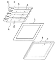
本発明は、し渣を捕捉するバースクリーン21を水路に設置し、フラップゲート11が逆流による水圧を受けたとき、このフラップゲート11を構成する板部材が、バースクリーン21の各バー22の下流側端面22aに当接した状態でバースクリーン21の目開部23(図4)を閉塞する構成としたことを主な特徴とする。
In the present invention, when a
本実施形態のバースクリーン21は、複数のバー22を縦にして水路幅方向に並設してなる、いわゆる縦引きタイプのスクリーンである。図4に示すように、各バー22は平板状の部材からなり、連結棒24により互いに連結される。図1から判るように、上方が上流寄りに位置するように傾斜状に設置される。
The
雨水吐き室1の対向する側壁間にわたってスクリーン支軸26が水平状に掛け渡されており、各バー22の上端にわたって固設した円筒部材25がこのスクリーン支軸26に回動可能に外嵌している。つまり、バースクリーン21は、上端が水平方向のスクリーン支軸26回りに回動可能に支持された構造となっている。通常時、バースクリーン21の下端は、バースクリーン21の自重により、越流せき4の上部に形成された段差側壁4aに当接した状態となっている。
A
フラップゲート11は、その上端が水平方向のゲート支軸12回りに回動可能に支持される。本実施形態では、蝶番13をフラップゲート11の上端と円筒部材25とにわたって取り付け、この蝶番13の回転軸をゲート支軸12としている。フラップゲート11は、矩形状の板部材、例えばステンレス鋼板から構成される。フラップゲート11が閉じている際、フラップゲート11の板面は各バー22の下流側端面22aに当接した状態となる。
The upper end of the
フラップゲート11が閉じて逆流による水圧を受けた際のフラップゲート11とバースクリーン21との間の水密性を確保するため、図4に示すように、バースクリーン21の外縁4辺全体にわたって当て板27が固設されており、フラップゲート11側においては、当て板27に密着可能となるようにその外縁4辺全体にわたってゴム材等からなるシール部材14が固設されている。
In order to ensure the watertightness between the
また、フラップゲート11とバースクリーン21とは連結部材15により連結されている。連結部材15は、バースクリーン21に対するフラップゲート11の回動を許容しつつ両者を連結する部材からなり、好適例としてはチェーンが挙げられる。連結部材15は、フラップゲート11が所定の開度位置に達して以降、フラップゲート11の回動力をバースクリーン21側に伝達する機能を有する。
Further, the
本発明の作用を説明する。通常時には、図1に示すように、バースクリーン21の下端は、バースクリーン21の自重により、越流せき4の段差側壁4aに当接した状態であり、フラップゲート11は自重により閉じて、フラップゲート11の板面はバースクリーン21の各バー22の下流側端面22aに当接した状態となる。したがって、フラップゲート11が河川等からの逆流による水圧を受けたときも、このフラップゲート11を構成する板部材が、各バー22の下流側端面22aに当接した状態でバースクリーン21の目開部23(図4)を閉塞する。
The operation of the present invention will be described. Normally, as shown in FIG. 1, the lower end of the
逆流による水圧の問題に対し、従来のフラップゲートの構造では補強用のリブを要していたのに対し、本発明では、フラップゲート11を構成する板部材を複数のバー22の下流側端面22aに当接支持させる構造としたので、フラップゲート11に加わる水圧による力を複数のバー22に分散させて効果的に逃がすことができる。これにより、フラップゲート11に格別な補強対策を施すことなく、フラップゲート11を単体の板部材のみから構成することができる。したがって、フラップゲート11の製造コストが安価となり、施工現場までの搬送時や取り付け時におけるフラップゲート11の取り扱いが容易となる。
In contrast to the problem of water pressure due to backflow, the conventional flap gate structure requires a reinforcing rib, whereas in the present invention, the plate members constituting the
次に、正常な流れ時において、大雨等により合流通路2からの水量が多くなって水位が越流せき4の上端よりも上昇した場合について説明する。雨天水位となったとき、水圧がバースクリーン21の目開部23(図4)を介してフラップゲート11の板面に加わり、フラップゲート11が所定値以上の水圧を受けた際、先ず図3(b)に示すようにフラップゲート11が下水に押し上げられて開く。そして、フラップゲート11が所定の開度位置まで達すると、連結部材15を構成するチェーンが延びきった状態となり、これ以降、フラップゲート11は図3(c)に示すように、チェーンを介してバースクリーン21を引き上げ回動させながら開いていく構造となっている。
Next, a description will be given of a case where the amount of water from the merging
バースクリーン21の下端が持ち上がるので、勿論、下水中の一部のし渣はバースクリーン21に捕捉されることなく、バースクリーン21の下端と越流せき4の上端との間隙からそのまま流れ出ることになる。この構造は、フラップゲート11がバースクリーン21を引き上げ可能なほどの水圧を受けているとき、つまり水位が異常なほどに上昇したとき、バースクリーン21の各バー22も水流に対して抵抗体となることから、下水をバースクリーン21に通すことなく、とにかく河川側へ大量に流したい場合に有効となる。
Since the lower end of the
なお、バースクリーン21が閉じている際、バースクリーン21の縁部は、雨水吐き室1の躯体側に形成された戸当り(図示せず)に当接している。この戸当りとの水密性を確保するため、前記シール部材14と同様のゴム材等からなるシール部材がバースクリーン21の縁部に固設される。
When the
以上、本発明について好適な実施形態を説明した。本発明は、説明した形態に限られることなくその趣旨を逸脱しない範囲で適宜に設計変更が可能である。例えば説明した形態ではバースクリーン21を可動式としたが、固定式としてもよい。また、バースクリーン21を回動させるに当たり、アクチュエータ等の開閉装置を別途設けてもよい。
The preferred embodiments of the present invention have been described above. The present invention is not limited to the embodiment described above, and can be modified as appropriate without departing from the spirit of the present invention. For example, although the
さらに、連結部材15としては、チェーンの他に、通常時は折り畳まれた状態となり、フラップゲート11が開くと延びるリンクアーム等から構成することもできる。また、バースクリーン21は、バー22を横にして上下方向に並設した、いわゆる横引きタイプのスクリーンであってもよい。さらに、バースクリーン21に掻き揚げ式のレーキ装置を設けてもよい。また、本発明は、下水道の他に河川や工業用水路等にも適用可能である。
In addition to the chain, the connecting
1 雨水吐き室
4 越流せき
11 フラップゲート
12 ゲート支軸
15 連結部材
21 バースクリーン
22 バー
22a 下流側端面
23 目開部
26 スクリーン支軸
DESCRIPTION OF
Claims (3)
し渣を捕捉するバースクリーンを水路に設置し、
フラップゲートが逆流による水圧を受けたとき、このフラップゲートを構成する板部材が、前記バースクリーンの各バーの下流側端面に当接した状態で前記バースクリーンの目開部を閉塞する構成としたことを特徴とするフラップゲートの構造。 It is a structure of a flap gate for preventing backflow, the upper end of which is supported so as to be rotatable around a horizontal gate spindle,
Install a bar screen in the water channel to catch the residue
When the flap gate receives water pressure due to the reverse flow, the plate member constituting the flap gate is configured to close the opening portion of the bar screen in a state of being in contact with the downstream end face of each bar of the bar screen. A flap gate structure characterized by that.
前記フラップゲートと前記バースクリーンとは連結部材により連結され、
正常な流れ時において前記フラップゲートが所定値以上の水圧を受けた際、先に前記フラップゲートが開き始めて所定の開度位置まで達して以降、このフラップゲートは前記連結部材を介して前記バースクリーンを引き上げ回動させながら開いていく構成としたことを特徴とする請求項1に記載のフラップゲートの構造。 The bar screen is supported such that the upper end thereof is rotatable around a horizontal screen support shaft,
The flap gate and the bar screen are connected by a connecting member,
When the flap gate receives a water pressure of a predetermined value or more during normal flow, the flap gate starts to open first and reaches a predetermined opening position. After that, the flap gate is connected to the bar screen via the connecting member. 2. The flap gate structure according to claim 1, wherein the flap gate is opened while being pivoted.
Priority Applications (1)
| Application Number | Priority Date | Filing Date | Title |
|---|---|---|---|
| JP2006242681A JP4644171B2 (en) | 2006-09-07 | 2006-09-07 | Flap gate structure |
Applications Claiming Priority (1)
| Application Number | Priority Date | Filing Date | Title |
|---|---|---|---|
| JP2006242681A JP4644171B2 (en) | 2006-09-07 | 2006-09-07 | Flap gate structure |
Publications (2)
| Publication Number | Publication Date |
|---|---|
| JP2008063820A JP2008063820A (en) | 2008-03-21 |
| JP4644171B2 true JP4644171B2 (en) | 2011-03-02 |
Family
ID=39286767
Family Applications (1)
| Application Number | Title | Priority Date | Filing Date |
|---|---|---|---|
| JP2006242681A Active JP4644171B2 (en) | 2006-09-07 | 2006-09-07 | Flap gate structure |
Country Status (1)
| Country | Link |
|---|---|
| JP (1) | JP4644171B2 (en) |
Families Citing this family (2)
| Publication number | Priority date | Publication date | Assignee | Title |
|---|---|---|---|---|
| CN111017234B (en) * | 2019-12-24 | 2023-08-04 | 中国航空工业集团公司西安飞机设计研究所 | One-way valve device for ventilation pipeline of aircraft fuel system |
| CN113477642B (en) * | 2021-06-05 | 2022-06-14 | 阳泉鑫丰溢科技有限公司 | Waste zinc-containing material packaging bag recycling and cleaning device |
Citations (3)
| Publication number | Priority date | Publication date | Assignee | Title |
|---|---|---|---|---|
| JPH0311165U (en) * | 1989-06-20 | 1991-02-04 | ||
| JP2002275860A (en) * | 2001-03-16 | 2002-09-25 | Maezawa Ind Inc | Scale spacing adjusting member of bar screen, scale spacing adjusting bar screen and drainage pump protective system having scale spacing adjusting bar screen |
| JP2005076382A (en) * | 2003-09-03 | 2005-03-24 | Shin Meiwa Ind Co Ltd | Dust collector |
-
2006
- 2006-09-07 JP JP2006242681A patent/JP4644171B2/en active Active
Patent Citations (3)
| Publication number | Priority date | Publication date | Assignee | Title |
|---|---|---|---|---|
| JPH0311165U (en) * | 1989-06-20 | 1991-02-04 | ||
| JP2002275860A (en) * | 2001-03-16 | 2002-09-25 | Maezawa Ind Inc | Scale spacing adjusting member of bar screen, scale spacing adjusting bar screen and drainage pump protective system having scale spacing adjusting bar screen |
| JP2005076382A (en) * | 2003-09-03 | 2005-03-24 | Shin Meiwa Ind Co Ltd | Dust collector |
Also Published As
| Publication number | Publication date |
|---|---|
| JP2008063820A (en) | 2008-03-21 |
Similar Documents
| Publication | Publication Date | Title |
|---|---|---|
| KR101351063B1 (en) | dust separator for pump and pump gate of one body type having dust separator | |
| KR101146131B1 (en) | Using buoyancy for automatic closing pide door devices and method of control | |
| JP4339912B2 (en) | Sediment inflow prevention device for interceptor pipe | |
| US20120279586A1 (en) | Unpowered apparatus for preventing backflow | |
| CN106836439A (en) | One kind is emergent from opening device | |
| JP5697695B2 (en) | Pull-up type flap in gate | |
| JP5361096B1 (en) | Water gate | |
| JP4644171B2 (en) | Flap gate structure | |
| JP2013096122A (en) | Flap gate | |
| KR100885968B1 (en) | Apparatus selectively opening and closing floodgate | |
| JP2015212517A (en) | Tide gate and tide gate installation method | |
| KR101224119B1 (en) | Non power floodgate of culvert | |
| CN210086460U (en) | Hydraulic rotating weir gate, diversion well provided with weir gate and control system of diversion well | |
| KR20080037749A (en) | Sluice-gate with a flap valve | |
| KR200166989Y1 (en) | Auto opening and closing device of a room for exhaust rain water in a drainpipe | |
| KR101235065B1 (en) | Support floodgate for draining ground water | |
| JP6490473B2 (en) | Pull-up type flap-in gate installation method | |
| KR101322010B1 (en) | Floodgate appartus | |
| KR200427611Y1 (en) | Gate Apparatus Having Flap Valve | |
| KR101922437B1 (en) | flood gate of draining pump plant | |
| KR20140065986A (en) | Pump gate device | |
| JP7382652B2 (en) | flap gate | |
| KR200371612Y1 (en) | A river watergate for preventing separate and back flow, using gasket | |
| CN216238872U (en) | Closable rainwater grate | |
| JP3088524U (en) | Gate pump equipment with auxiliary gate |
Legal Events
| Date | Code | Title | Description |
|---|---|---|---|
| A621 | Written request for application examination |
Free format text: JAPANESE INTERMEDIATE CODE: A621 Effective date: 20090602 |
|
| A977 | Report on retrieval |
Free format text: JAPANESE INTERMEDIATE CODE: A971007 Effective date: 20101119 |
|
| TRDD | Decision of grant or rejection written | ||
| A01 | Written decision to grant a patent or to grant a registration (utility model) |
Free format text: JAPANESE INTERMEDIATE CODE: A01 Effective date: 20101130 |
|
| A01 | Written decision to grant a patent or to grant a registration (utility model) |
Free format text: JAPANESE INTERMEDIATE CODE: A01 |
|
| A61 | First payment of annual fees (during grant procedure) |
Free format text: JAPANESE INTERMEDIATE CODE: A61 Effective date: 20101203 |
|
| R150 | Certificate of patent or registration of utility model |
Ref document number: 4644171 Country of ref document: JP Free format text: JAPANESE INTERMEDIATE CODE: R150 Free format text: JAPANESE INTERMEDIATE CODE: R150 |
|
| FPAY | Renewal fee payment (event date is renewal date of database) |
Free format text: PAYMENT UNTIL: 20131210 Year of fee payment: 3 |