JP4642305B2 - Method and apparatus for entering and exiting multiple threads within a multithreaded processor - Google Patents
Method and apparatus for entering and exiting multiple threads within a multithreaded processor Download PDFInfo
- Publication number
- JP4642305B2 JP4642305B2 JP2001542717A JP2001542717A JP4642305B2 JP 4642305 B2 JP4642305 B2 JP 4642305B2 JP 2001542717 A JP2001542717 A JP 2001542717A JP 2001542717 A JP2001542717 A JP 2001542717A JP 4642305 B2 JP4642305 B2 JP 4642305B2
- Authority
- JP
- Japan
- Prior art keywords
- thread
- event
- processor
- threads
- state
- Prior art date
- Legal status (The legal status is an assumption and is not a legal conclusion. Google has not performed a legal analysis and makes no representation as to the accuracy of the status listed.)
- Expired - Fee Related
Links
- 238000000034 method Methods 0.000 title claims abstract description 85
- 230000007704 transition Effects 0.000 claims abstract description 23
- 230000008859 change Effects 0.000 claims abstract description 18
- 239000000872 buffer Substances 0.000 claims description 56
- 230000004044 response Effects 0.000 claims description 30
- 238000001514 detection method Methods 0.000 claims description 28
- 230000006870 function Effects 0.000 claims description 25
- 230000008569 process Effects 0.000 claims description 19
- 238000013519 translation Methods 0.000 claims description 6
- 238000004148 unit process Methods 0.000 claims 1
- 238000000638 solvent extraction Methods 0.000 abstract description 2
- 238000010586 diagram Methods 0.000 description 45
- 239000003550 marker Substances 0.000 description 30
- 230000001360 synchronised effect Effects 0.000 description 19
- 238000012545 processing Methods 0.000 description 17
- 230000003139 buffering effect Effects 0.000 description 10
- 238000013461 design Methods 0.000 description 10
- 238000007726 management method Methods 0.000 description 10
- 239000013598 vector Substances 0.000 description 10
- 238000006243 chemical reaction Methods 0.000 description 8
- 239000010813 municipal solid waste Substances 0.000 description 7
- 230000000644 propagated effect Effects 0.000 description 6
- 230000000694 effects Effects 0.000 description 5
- 238000005192 partition Methods 0.000 description 5
- 238000011084 recovery Methods 0.000 description 5
- 102100025250 C-X-C motif chemokine 14 Human genes 0.000 description 4
- 101000858068 Homo sapiens C-X-C motif chemokine 14 Proteins 0.000 description 4
- 238000012384 transportation and delivery Methods 0.000 description 4
- 238000004891 communication Methods 0.000 description 3
- 230000009471 action Effects 0.000 description 2
- 230000008901 benefit Effects 0.000 description 2
- 238000004883 computer application Methods 0.000 description 2
- 238000013479 data entry Methods 0.000 description 2
- 239000004579 marble Substances 0.000 description 2
- 239000011159 matrix material Substances 0.000 description 2
- 230000007246 mechanism Effects 0.000 description 2
- 230000004048 modification Effects 0.000 description 2
- 238000012986 modification Methods 0.000 description 2
- 230000010076 replication Effects 0.000 description 2
- 230000000630 rising effect Effects 0.000 description 2
- 230000001960 triggered effect Effects 0.000 description 2
- 230000003213 activating effect Effects 0.000 description 1
- 230000004913 activation Effects 0.000 description 1
- 230000002411 adverse Effects 0.000 description 1
- 238000013459 approach Methods 0.000 description 1
- 230000006399 behavior Effects 0.000 description 1
- 238000004364 calculation method Methods 0.000 description 1
- 230000001419 dependent effect Effects 0.000 description 1
- 230000000779 depleting effect Effects 0.000 description 1
- 238000011156 evaluation Methods 0.000 description 1
- 230000007717 exclusion Effects 0.000 description 1
- 238000011010 flushing procedure Methods 0.000 description 1
- 230000017525 heat dissipation Effects 0.000 description 1
- 230000006872 improvement Effects 0.000 description 1
- 230000000977 initiatory effect Effects 0.000 description 1
- 230000006386 memory function Effects 0.000 description 1
- 230000002085 persistent effect Effects 0.000 description 1
- 238000012913 prioritisation Methods 0.000 description 1
- 238000013468 resource allocation Methods 0.000 description 1
- 230000002441 reversible effect Effects 0.000 description 1
- 239000000523 sample Substances 0.000 description 1
- 238000012163 sequencing technique Methods 0.000 description 1
- 230000001629 suppression Effects 0.000 description 1
- 238000010200 validation analysis Methods 0.000 description 1
Images


Classifications
-
- G—PHYSICS
- G06—COMPUTING; CALCULATING OR COUNTING
- G06F—ELECTRIC DIGITAL DATA PROCESSING
- G06F9/00—Arrangements for program control, e.g. control units
- G06F9/06—Arrangements for program control, e.g. control units using stored programs, i.e. using an internal store of processing equipment to receive or retain programs
- G06F9/30—Arrangements for executing machine instructions, e.g. instruction decode
- G06F9/30145—Instruction analysis, e.g. decoding, instruction word fields
- G06F9/30149—Instruction analysis, e.g. decoding, instruction word fields of variable length instructions
- G06F9/30152—Determining start or end of instruction; determining instruction length
-
- G—PHYSICS
- G06—COMPUTING; CALCULATING OR COUNTING
- G06F—ELECTRIC DIGITAL DATA PROCESSING
- G06F9/00—Arrangements for program control, e.g. control units
- G06F9/06—Arrangements for program control, e.g. control units using stored programs, i.e. using an internal store of processing equipment to receive or retain programs
- G06F9/30—Arrangements for executing machine instructions, e.g. instruction decode
- G06F9/38—Concurrent instruction execution, e.g. pipeline or look ahead
- G06F9/3802—Instruction prefetching
- G06F9/3808—Instruction prefetching for instruction reuse, e.g. trace cache, branch target cache
-
- G—PHYSICS
- G06—COMPUTING; CALCULATING OR COUNTING
- G06F—ELECTRIC DIGITAL DATA PROCESSING
- G06F9/00—Arrangements for program control, e.g. control units
- G06F9/06—Arrangements for program control, e.g. control units using stored programs, i.e. using an internal store of processing equipment to receive or retain programs
- G06F9/30—Arrangements for executing machine instructions, e.g. instruction decode
- G06F9/38—Concurrent instruction execution, e.g. pipeline or look ahead
- G06F9/3818—Decoding for concurrent execution
- G06F9/382—Pipelined decoding, e.g. using predecoding
-
- G—PHYSICS
- G06—COMPUTING; CALCULATING OR COUNTING
- G06F—ELECTRIC DIGITAL DATA PROCESSING
- G06F9/00—Arrangements for program control, e.g. control units
- G06F9/06—Arrangements for program control, e.g. control units using stored programs, i.e. using an internal store of processing equipment to receive or retain programs
- G06F9/30—Arrangements for executing machine instructions, e.g. instruction decode
- G06F9/38—Concurrent instruction execution, e.g. pipeline or look ahead
- G06F9/3836—Instruction issuing, e.g. dynamic instruction scheduling or out of order instruction execution
- G06F9/3838—Dependency mechanisms, e.g. register scoreboarding
- G06F9/384—Register renaming
-
- G—PHYSICS
- G06—COMPUTING; CALCULATING OR COUNTING
- G06F—ELECTRIC DIGITAL DATA PROCESSING
- G06F9/00—Arrangements for program control, e.g. control units
- G06F9/06—Arrangements for program control, e.g. control units using stored programs, i.e. using an internal store of processing equipment to receive or retain programs
- G06F9/30—Arrangements for executing machine instructions, e.g. instruction decode
- G06F9/38—Concurrent instruction execution, e.g. pipeline or look ahead
- G06F9/3836—Instruction issuing, e.g. dynamic instruction scheduling or out of order instruction execution
- G06F9/3851—Instruction issuing, e.g. dynamic instruction scheduling or out of order instruction execution from multiple instruction streams, e.g. multistreaming
-
- G—PHYSICS
- G06—COMPUTING; CALCULATING OR COUNTING
- G06F—ELECTRIC DIGITAL DATA PROCESSING
- G06F9/00—Arrangements for program control, e.g. control units
- G06F9/06—Arrangements for program control, e.g. control units using stored programs, i.e. using an internal store of processing equipment to receive or retain programs
- G06F9/30—Arrangements for executing machine instructions, e.g. instruction decode
- G06F9/38—Concurrent instruction execution, e.g. pipeline or look ahead
- G06F9/3854—Instruction completion, e.g. retiring, committing or graduating
- G06F9/3856—Reordering of instructions, e.g. using queues or age tags
-
- G—PHYSICS
- G06—COMPUTING; CALCULATING OR COUNTING
- G06F—ELECTRIC DIGITAL DATA PROCESSING
- G06F9/00—Arrangements for program control, e.g. control units
- G06F9/06—Arrangements for program control, e.g. control units using stored programs, i.e. using an internal store of processing equipment to receive or retain programs
- G06F9/30—Arrangements for executing machine instructions, e.g. instruction decode
- G06F9/38—Concurrent instruction execution, e.g. pipeline or look ahead
- G06F9/3854—Instruction completion, e.g. retiring, committing or graduating
- G06F9/3858—Result writeback, i.e. updating the architectural state or memory
-
- G—PHYSICS
- G06—COMPUTING; CALCULATING OR COUNTING
- G06F—ELECTRIC DIGITAL DATA PROCESSING
- G06F9/00—Arrangements for program control, e.g. control units
- G06F9/06—Arrangements for program control, e.g. control units using stored programs, i.e. using an internal store of processing equipment to receive or retain programs
- G06F9/30—Arrangements for executing machine instructions, e.g. instruction decode
- G06F9/38—Concurrent instruction execution, e.g. pipeline or look ahead
- G06F9/3861—Recovery, e.g. branch miss-prediction, exception handling
- G06F9/3863—Recovery, e.g. branch miss-prediction, exception handling using multiple copies of the architectural state, e.g. shadow registers
-
- G—PHYSICS
- G06—COMPUTING; CALCULATING OR COUNTING
- G06F—ELECTRIC DIGITAL DATA PROCESSING
- G06F9/00—Arrangements for program control, e.g. control units
- G06F9/06—Arrangements for program control, e.g. control units using stored programs, i.e. using an internal store of processing equipment to receive or retain programs
- G06F9/30—Arrangements for executing machine instructions, e.g. instruction decode
- G06F9/38—Concurrent instruction execution, e.g. pipeline or look ahead
- G06F9/3885—Concurrent instruction execution, e.g. pipeline or look ahead using a plurality of independent parallel functional units
- G06F9/3888—Concurrent instruction execution, e.g. pipeline or look ahead using a plurality of independent parallel functional units controlled by a single instruction for multiple threads [SIMT] in parallel
Landscapes
- Engineering & Computer Science (AREA)
- Software Systems (AREA)
- Theoretical Computer Science (AREA)
- Physics & Mathematics (AREA)
- General Engineering & Computer Science (AREA)
- General Physics & Mathematics (AREA)
- Multimedia (AREA)
- Advance Control (AREA)
- Debugging And Monitoring (AREA)
- Memory System Of A Hierarchy Structure (AREA)
- Peptides Or Proteins (AREA)
- Medicines That Contain Protein Lipid Enzymes And Other Medicines (AREA)
- Hardware Redundancy (AREA)
- Mobile Radio Communication Systems (AREA)
- Multi Processors (AREA)
Abstract
Description
【0001】
(発明の分野)
本発明は、一般に、マルチスレッド・プロセッサに関するものであり、より具体的には、マルチスレッド(MT)プロセッサ内の複数のスレッドに入り、そこから出る方法と装置に関するものである。
【0002】
(発明の背景)
マルチスレッド(MT)プロセッサの設計は近年、プロセッサの性能を上げるうえで非常に魅力的なオプションとして考えられるようになってきている。とりわけプロセッサ内でマルチスレッドで動作させると、各種のプロセッサ・リソースをより効果的に利用することができる可能性があり、特にプロセッサ内の実行ロジックをより効果的に利用できることが考えられる。特に、複数のスレッドをプロセッサの実行ロジックに送ることで、そうしなかった場合に特定のスレッドの処理が停止していたり他の何らかの遅延が生じてアイドル状態にあるクリック・サイクルを利用して、さらにスレッドを処理できる。特定のスレッドの処理の停止は、プロセッサ内のパイプライン内で実行が多い場合に生じる。たとえば、スレッド内にキャッシュ・ミスまたは分岐予測誤り(つまり、待ち時間の長い動作)が含まれると、通常、関連するスレッド停止の処理が行われる。長い待ち時間の動作が実行ロジックの効率に及ぼすマイナスの効果は、メモリ・アクセスおよび取得速度の向上をしのぐ実行ロジックのスループットの近年の増大により悪化している。
【0003】
マルチスレッド・コンピュータ・アプリケーションは、さらに、Windows(登録商標) NTやUnix(登録商標)オペレーティング・システムなど普及している多くのオペレーティング・システムによってこのようなマルチスレッド・アプリケーションがサポートされ、次第に一般的なものとなってきている。マルチスレッド・コンピュータ・アプリケーションは、特にマルチメディア分野で効率がよい。
【0004】
大まかに言うと、マルチスレッド・プロセッサは、関連するプロセッサ内で採用されているスレッドのインタリーブすなわち切り替え方式に応じて、2つのカテゴリ(つまり、密設計または疎設計)に分類できる。密マルチスレッド設計では、プロセッサ内に複数のアクティブ・スレッドをサポートし、通常、2つの異なるスレッドをサイクルごとにインタリーブする。疎マルチスレッド設計では、通常、キャッシュ・ミスなどの待ち時間が長くなるイベントが発生すると異なるスレッドの命令をインタリーブする。疎マルチスレッド設計については、Eickemayer, R.、Johnson, R.、他著「Evaluation of Multithreaded Uniprocessors for Commercial Application Environments」(The 23rd Annual International Symposium on Computer Architecture, pp. 203−212, May 1996)で説明されている。密設計と疎設計の違いについては、Laudon, J、Gupta, A著「Architectural and Implementation Tradeoffs in the Design of Multiple−Context Processors」(Multithreaded Computer Architectures: A Summary of the State of the Art, R.A. Iannuci 他、編、pp. 167−200, Kluwer Academic Publishers, Norwell, Massachusetts, 1994)で詳述されている。Laudonはさらに、密設計のサイクルごとの切り替えと疎設計の完全パイプライン・インターロックとを組合せるインタリーブ方式(またはブロック方式)を提案している。このために、Laudonは特定のサイクル数分について特定のスレッド(またはコンテキスト)を使用できないようにする「バックオフ」命令を提案している。このような「バックオフ」命令は、キャッシュ・ミスなどのあらかじめ決められているイベントの発生があったときに発行される。Laudonは、この方法で、単にスレッドの1つを使用不能にすることで実際のスレッド切り替えを実行しなくてすむようにしている。
【0005】
プロセッサのマルチスレッドされたアーキテクチャでは、順序が狂っている推測実行プロセッサのアーキテクチャ・コンテキストにおいてさらに多くの問題を抱える。具体的には、命令ストリームの流れに予期しない変化を引き起こす可能性のあるイベント(たとえば、分岐命令、例外、または割り込み)の処理は、複数のスレッドを考慮した場合に複雑なものとなる。複数のスレッド間のリソース共有を実装した場合(つまり、プロセッサによってサポートされる各スレッドについて機能ユニットの重複に制限があるか、またはない)、特定のスレッドに関するイベント発生の処理は、そのようなイベントの処理でさらにスレッドを考慮する必要があるという点で複雑になる。
【0006】
リソース共有がマルチスレッド・プロセッサ内に実装されている場合、マルチスレッド・プロセッサ内で処理されるスレッドの状態の変化に対応して共有リソースの利用度を高めることがさらに望ましい。
【0007】
(発明の概要)
本発明では、マルチビット出力を備えるステート・マシンを保持し、マルチビット出力のそれぞれのビットがマルチスレッド・プロセッサ内で実行される複数のスレッドのうち関連するスレッドのそれぞれのステータスを示す方法を提示している。マルチスレッド・プロセッサ内の第1のスレッドのステータスの変化が検出される。マルチスレッド・プロセッサ内の機能ユニットは、ステート・マシンのマルチビット出力に応じて構成される。
【0008】
本発明の他の特徴は、付属の図面と後の詳細な説明から明らかであろう。
【0009】
本発明は、同様の参照は同様の要素を表す付属の図面の図で、例を使って説明するが、これに限定されるわけではない。
【0010】
(詳細な説明)
マルチスレッド・プロセッサ内の複数のスレッドに入り、出る方法と装置について説明する。以下の説明では、説明のため本発明を完全に理解できるように多数の特定の詳細を定めている。ただし、当業者であれば、こうした具体的内容がなくても本発明を実践できることは明白であろう。
【0011】
本明細書の目的のために、「イベント」という用語は、プロセッサ内の命令ストリーム(マクロ命令またはマイクロ命令)の処理の変更または中断を行う、プロセッサの内部または外部のイベントを含むものとして解釈するものとする。したがって、「イベント」という用語は、プロセッサの内部または外部で発生する可能性のある分岐命令プロセス、例外および中断を含むものと解釈するが、ただしこれに限られるわけではない。
【0012】
本明細書の目的のために、「プロセッサ」という用語は、命令(たとえば、マクロ命令またはマイクロ命令)のシーケンスを実行できるマシンを意味すると解釈し、汎用マイクロプロセッサ、専用マイクロプロセッサ、グラフィック・コントローラ、オーディオ・コントローラ、マルチメディア・コントローラ、マイクロコントローラ、またはネットワーク・コントローラを含むものと解釈するが、ただしこれらに限られるわけではない。さらに、「プロセッサ」という用語は、なかんずく、CISC(Complex Instruction Set Computers)、RISC(Reduced Instruction Set Computers)、またはVLIW(Very Long Instruction Word)の各プロセッサを意味するものとする。
【0013】
さらに、「クリアリング・ポイント」という用語は、イベントを取り扱う、または処理できる命令ストリーム内の場所のフロー・マーカまたはその他の命令による命令ストリーム(マイクロ命令またはマクロ命令ストリームを含む)内に用意された命令を含むものと解釈する。
【0014】
「命令」という用語は、マクロ命令またはマイクロ命令を含むものと解釈するが、これらに限られない。
【0015】
本発明の例示的な実施形態については、ハードウェアかソフトウェアで主に実施されるものとして説明している。しかしながら、当業者であれば、多くの機能をハードウェア、ソフトウェア、またはハードウェアとソフトウェアの組合せで実施できることは理解されるであろう。
【0016】
本発明の実施形態を実施するソフトウェア(たとえば、マイクロ命令およびマクロ命令)は、プロセッサによってかつ/またはプロセッサ自体(たとえば、キャッシュまたはマイクロコード・シーケンサ)内でアクセス可能なメイン・メモリ内に全部または少なくとも一部常駐する。たとえば、イベント・ハンドラおよびステート・マシンは、マイクロコード・シーケンサからディスパッチされたマイクロコードとして実装できる。
【0017】
ソフトウェアはさらに、ネットワーク・インタフェース・デバイスを介して送受信できる。
【0018】
本明細書の目的のために、「機械読み取り可能媒体」という用語は、マシンから実行できる命令のシーケンスを格納またはエンコードし、マシンに本発明の方法の1つを実行させることができる媒体を含むものと解釈する。「機械読み取り可能媒体」という用語は、したがって、ソリッドステート・メモリ、光磁気ディスク、およびキャリア波信号を含むものと解釈するが、ただしこれらに限られるわけではない。
【0019】
プロセッサ・パイプライン
図1は、プロセッサ・パイプライン10の一実施形態を示す高レベル・ブロック図である。パイプライン10は、命令(たとえば、マクロ命令)を取り出し、パイプライン10に送るフェッチ・パイプ段12から開始する、多数のパイプ段を含む。たとえば、マクロ命令は、プロセッサに搭載された、あるいはそれと密接に関連するキャッシュ・メモリから取り出すことも、またプロセッサ・バスを介して外部メイン・メモリから取り出すこともできる。フェッチ・パイプ段12から、マクロ命令がパイプ・デコード段14に送られ、そこでマクロ命令はプロセッサ内で実行するのに適したマイクロ命令(「マイクロコード」とも呼ばれる)に翻訳される。その後、マイクロ命令は、パイプ割り当て段16の下流に伝播され、そこで、使用可能かどうか、また必要かどうかに応じて、プロセッサ・リソースが各種のマイクロ命令に割り当てられる。それから、マイクロ命令は実行段18で実行された後、パイプ・リタイヤ段20でリタイヤする、つまり「書き戻される」(たとえば、アーキテクチャ状態にコミットされる)。
【0020】
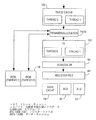
マイクロプロセッサ・アーキテクチャ
図2は、汎用マイクロプロセッサの形式のプロセッサ30の例示的な一実施形態を示すブロック図である。プロセッサ30は、以下で、マルチスレッド(MT)プロセッサとして説明されており、したがって、複数の命令スレッド(またはコンテキスト)を処理することができる。しかし、明細書の後のほうで取り上げている多くの教示は、マルチスレッド・プロセッサに特有のものではなく、シングル・スレッド・プロセッサにおけるアプリケーションもある。例示的な一実施形態では、プロセッサ30はインテル・アーキテクチャ(IA)のマイクロプロセッサを採用しており、インテル・アーキテクチャ命令セットを実行できる。このようなインテル・アーキテクチャ・マイクロプロセッサの例として、カリフォルニア州サンタクララを所在地とするIntel Corporationが製造するPentium (登録商標)ProまたはPentium IIIマイクロプロセッサがある。
【0021】
一実施形態では、プロセッサ30は順序正しいフロントエンドと順序正しくないバック・エンドを備える。順序正しいフロントエンドは、プロセッサ30とプロセッサ30が採用されている可能性のあるコンピュータ・システムの他のコンポーネント(たとえば、メインメモリ)とをつなぐコンジットとして機能するバス・インタフェース・ユニット32を備える。このために、バス・インタフェース・ユニット32は、プロセッサ30をプロセッサ・バス(図に示されていない)に結合し、このバスを介して、データおよび制御情報をプロセッサ30で受信し、プロセッサ30から伝播させることができる。バス・インタフェース・ユニット32は、プロセッサ・バス上の通信を制御するFSB(Front Side Bus)ロジック34を備える。バス・インタフェース・ユニット32はさらに、プロセッサ・バス上での通信に関してバッファリング機能を提供するバス・キュー36を備える。バス・インタフェース・ユニット32は、プロセッサ30内のローカル・メモリ機能を提供するメモリ実行ユニット42からバス要求38を受け取り、スヌープまたはバス・リターンをそのメモリ実行ユニット42に送ることが図に示されている。メモリ実行ユニット42は、統一データおよび命令キャッシュ44、データTLB(Translation Lookaside Buffer)46、およびメモリ順序付けバッファ48を備える。メモリ実行ユニット42は、受信したマクロ命令を対応するマイクロ命令セットに変換するマイクロ命令変換エンジン54から命令フェッチ要求50を受け取り、そのエンジンに生の命令52(つまり、コード化されたマイクロ命令)を送出する。
【0022】
マイクロ命令変換エンジン54は、実際には、トレース・キャッシュ「ミス・ハンドラ」として動作し、トレース・キャッシュ・ミスが発生した場合にマイクロ命令をトレース・キャッシュ62に送出する。このために、マイクロ命令変換エンジン54は、トレース・キャッシュ・ミスが発生した場合にパイプ・フェッチおよびパイプ・デコード段12および14を提供するように機能する。マイクロ命令変換エンジン54は、次命令ポインタ(NIP)100、命令TLB(Translation Lookaside Buffer)102、分岐予測器104、命令ストリーミング・バッファ106、命令プレデコーダ108、命令ステアリング・ロジック110、命令デコーダ112、および分岐アドレス計算器114を備えることが示されている。次命令ポインタ100、TLB 102、分岐予測器104、および命令ストリーミング・バッファ106はあわせて、分岐予測ユニット(BPU)99を構成する。命令デコーダ112および分岐アドレス計算器114はあわせて、命令変換(IX)ユニット113を備える。
【0023】
次命令ポインタ100は、次命令要求を統一キャッシュ44に発行する。プロセッサ30が2つのスレッドを処理できるマルチスレッド・マイクロプロセッサを備える例示的な実施形態では、次命令ポインタ100は、発行される次命令要求に含めるために、第1または第2のスレッドのいずれかと関連する命令ポインタを選択するマルチプレクサ(MUX)(図に示されていない)を備えることができる。一実施形態では、次命令ポインタ100は、サイクルごとに(「ピンポン方式」で)第1と第2のスレッドに対する次命令要求をインタリーブするが、ただし、両方のスレッドに対する命令が要求されており、両方のスレッドに対する命令ストリーミング・バッファ106リソースが尽きていないと仮定する。次命令ポインタ要求は、初期要求アドレスが32バイトまたは64バイト整合ラインの上半分にあるかどうかに応じて、16、32、または64バイトに対応する。次命令ポインタ100は、分岐予測器104、分岐アドレス計算器114、またはトレース・キャッシュ62によりリダイレクトすることができ、しかも、トレース・キャッシュ・ミス要求は最高優先度のリダイレクト要求となる。
【0024】
次命令ポインタ100が統一キャッシュ44への命令要求を行った場合に、命令要求と関連付けられた2ビットの「要求識別子」を生成し、関連命令要求の「タグ」として機能する。命令要求に応答するデータを戻すと、統一キャッシュ44は以下のタグまたは識別子をデータとともに返す。
1.次命令ポインタ100によって供給される「要求識別子」。
2.返されたチャンクを識別する3ビット「チャンク識別子」。
3.返されたデータが属すスレッドを識別する「スレッド識別子」。
【0025】
次命令要求は、次命令ポインタ100から命令TLB 102へ伝播され、これにより、アドレス検索オペレーションが実行され、物理的アドレスが統一キャッシュ44に送られる。統一キャッシュ44は、対応するマクロ命令を命令ストリーミング・バッファ106に送る。それぞれの次命令要求はさらに、次命令ポインタ100から直接命令ストリーミング・バッファ106に伝播され、命令ストリーミング・バッファ106で、統一キャッシュ44から受け取ったマクロ命令が属すスレッドを識別できる。第1と第2のスレッドの両方からのマクロ命令が、命令ストリーミング・バッファ106から命令プレデコーダ108に発行され、これにより、(マクロ命令の)受け取った命令ストリームに関して多数の長さ計算およびバイト・マーキング・オペレーションを実行する。特に、命令プレデコーダ108は、とりわけ、命令ステアリング・ロジック110に伝播する命令ストリーム内のマクロ命令を区別するために使用される一連のバイト・マーキング・ベクトルを生成する。
【0026】
その後、命令ステアリング・ロジック110は、バイト・マーキング・ベクトルを利用して、デコードを目的として命令デコーダ112への離散マクロ命令のステアリングを行う。マクロ命令はさらに、命令ステアリング・ロジック110から分岐アドレス計算器114に伝播され、分岐アドレスの計算が行われる。その後、マイクロ命令が命令デコーダ112からトレース送出エンジン60に送られる。
【0027】
デコード中、フロー・マーカがマクロ命令の変換先の各マイクロ命令と関連付けられる。フロー・マーカは、関連するマイクロ命令の特性を示し、たとえば、関連するマイクロ命令をマクロ命令を表すマイクロコード・シーケンス内の最初または最後のマイクロ命令であることを示す。フロー・マーカは、「マクロ命令の先頭」(BOM)および「マクロ命令の終わり」(EOM)というフロー・マーカを含む。本発明によれば、デコーダ112はさらに、マイクロ命令をデコードし、共有リソース(マルチプロセッサ)(SHRMP)フロー・マーカおよび同期(SYNC)フロー・マーカがそれと関連付けられる。特に、共有リソース・フロー・マーカは、マイクロ命令を、スレッド内の別の場所ほど結果が否定的でない、スレッドが中断する(たとえば、再起動、または一時停止)特定のスレッド内の場所として識別する。デコーダ112は、本発明の例示的な実施形態では、共有リソース・フロー・マーカとともに長いマイクロコード・シーケンス内の間歇的なポイントを持つ親マクロ命令の末尾または先頭を備えるマイクロ命令にマーク付けするように構成されている。同期フロー・マーカは、マイクロ命令を、たとえば、スレッドを他のスレッド内の同期命令に応答する他のスレッドと同期化できる特定のスレッド内のある場所として識別する。本明細書の目的のために、「同期化する」という用語は、そのスレッドに関してプロセッサ状態を修正できる少なくとも1つのスレッドおよび/またはプロセッサへの中断が低減されているまたは低い少なくとも1つの他のスレッドを、そのスレッドまたは他のスレッド内の第2のポイントに関して識別することを意味するものとする。
【0028】
デコーダ112は、本発明の例示的な実施形態では、同じプロセッサ内に共存するスレッド間で共有される状態を、一方のスレッドにより、他方のスレッドの実行に悪影響を及ぼすことなく変更できる選択されたマクロ命令境界に配置されているマイクロ命令をマークするように構成されている。
【0029】
デコードされた命令(つまりマイクロ命令)がマイクロ命令変換エンジン54からトレース送出エンジン60に送られる。トレース送出エンジン60は、トレース・キャッシュ62、トレース分岐予測器(BTB)64、マイクロコード・シーケンサ66、およびマイクロコード(uop)キュー68を備える。トレース送出エンジン60は、マイクロ命令キャッシュとして機能し、下流の実行ユニット70のマイクロ命令の一次ソースとなっている。マクロ命令キャッシュ機能をプロセッサ・パイプライン内に備えることにより、トレース送出エンジン60、および特にトレース・キャッシュ62により、マイクロ命令変換エジン54で行った変換作業を利用して、マイクロ命令帯域幅を拡大できる。例示的な一実施形態では、トレース・キャッシュ62は、256セット、8ウェイ・セットの連想メモリを備えている。本例示的な実施形態の「トレース」という用語は、トレース・キャッシュ62のエントリ内に格納されるマイクロ命令のシーケンスを意味し、それぞれのエントリはトレースを含む先行する、また続くマイクロ命令へのポインタを含む。このようにして、トレース・キャッシュ62を使用することで、高性能シーケンシング機能を簡単に利用でき、後続のマイクロ命令を取得するためにアクセスする次のエントリのアドレスが現在のアクセスの完了前に知られている。トレースは、一実施形態では、トレース・ヘッドによりお互いに区別される命令の「ブロック」とみなされ、間接分岐に遭遇した後、または単一トレースに収められる条件付分岐の数やトレースを含むことができるマイクロ命令全体の最大数など多数のこのしきい値条件のうちの1つに到達することにより終了する。
【0030】
トレース・キャッシュの分岐予測器64は、トレース・キャッシュ62内のトレースに関連するローカル分岐予測を行う。トレース・キャッシュ62およびマイクロコード・シーケンサ66は、マイクロ命令をマイクロコード・キュー68に送り、そこからマイクロ命令を順序外れ実行クラスタに供給される。マイクロコード・シーケンサ66は、さらに、例外や割り込みなどのイベントの発生に応じて、プロセッサ30内に多数のオペレーションを実装するマイクロコード内に組み込まれている多数のイベント・ハンドラ67を含むように示されている。イベント・ハンドラ67は、以下で詳述するように、プロセッサ30のバック・エンド内のレジスタ名前書き換え部74内に含まれるイベント検出器188により呼び出される。
【0031】
プロセッサ30は、バス・インタフェース・ユニット32、メモリ実行ユニット42、マクロ命令変換エンジン54、およびトレース送出エンジン60を備える順序正しいフロントエンド、および後述の順序外れバック・エンドを備えているものとみなすことができる。
【0032】
マイクロコード・キュー68からディスパッチされたマイクロ命令は、スケジューラ72、レジスタ名前書き換え部74、アロケータ76、リオーダ・バッファ78、およびリプレイ・キュー80を備える順序外れクラスタ71に入る。スケジューラ72は、1組の予約ステーションを備え、実行ユニット70によって実行されるマイクロ命令をスケジュールし、ディスパッチする。レジスタ名前書き換え部74は、整数および浮動小数点隠しレジスタに関してレジスタ名前書き換え機能を実行する(これを、プロセッサ30がインテル・アーキテクチャ命例セットを実行する、8本の汎用レジスタのどれかまたは8本の浮動小数点レジスタのどれかの代わりに使用できる)。アロケータ76は、使用可能かどうか、また必要かどうかに応じて、実行ユニット70およびクラスタの71のリソースをマイクロ命令に割り当てる動作をする。マイクロ命令を処理しようにもリソースが不十分な場合、アロケータ76は停止信号82をアサートする役割を持ち、図の58に示されているように、これはトレース送出エンジン60を介して、マイクロ命令変換エンジン54に伝播される。マイクロ命令は、レジスタ名前書き換え部74によって調整されるソース・フィールドを持っており、厳密なプログラム順序でリオーダ・バッファ78に置かれる。リオーダ・バッファ78内のマイクロ命令が実行を完了し、リタイヤの準備ができたら、リオーダ・バッファから取り出され、順序どおり取り出される(つまり、元のプログラム順序に応じて)。リプレイ・キュー80は、リプレイされるマイクロ命令を実行ユニット70に伝播する。
【0033】
実行ユニット70は、浮動小数点実行工エンジン84、整数実行エンジン86、およびレベル0データ・キャッシュ88を備えることが示されている。プロセッサ30である例示的な一実施形態では、インテル・アーキテクチャ命令セットが実行され、浮動小数点実行エンジン84はさらに、MMX(登録商標)命令およびストリーミングSIMD(Single Instruction、Multiple Data)拡張(SSE)を実行できる。
【0034】
マルチスレッドの実装
図2に示されているプロセッサ30の例示的な実施形態では、マルチスレッド機能をサポートするリソースの複製またはレプリケーションが限られている場合があり、したがってスレッド間である程度のリソース共有を実装する必要がある。採用しているリソース共有方式は、プロセッサが同時に処理できるスレッドの数に左右されることは理解されるであろう。プロセッサ内の機能ユニットは通常、ある程度のバッファリング(または格納)機能と伝播機能を備えており、リソース共有の問題は、(1)格納と(2)帯域幅共有コンポーネントの処理/伝播を含むものとみなすことができる。たとえば、2つのスレッドの同時処理をサポートするプロセッサでは、さまざまな機能ユニット内のバッファ・リソースは2つのスレッドに静的にまたは論理的に分割することができる。同様に、2つの機能ユニット間の情報の伝播の経路で与えられる帯域幅を2つのスレッドに分割し、割り当てることができる。これらのリソース共有問題は、プロセッサ・パイプライン内の多数の場所で発生することがあるため、異なるリソース共有方式を特定の場所の指示と特性に応じてさまざまな場所で使用できる。さまざまな機能および動作特性を鑑みて、異なるリソース共有方式は異なる場所に適していることは理解されるであろう。
【0035】
図3は、図2に示されているプロセッサ30の一実施形態の選択されたコンポーネントを示すブロック図であり、バッファリング機能を備えるさまざまな機能ユニットを2つのスレッド(つまり、スレッド0およびスレッド1)に対応して論理的に分割されたものとして示す。機能ユニットのバッファリング(または格納)機能および処理機能の2つのスレッドを論理的パーティション分割するには、バッファリング・リソース内のエントリの第1の所定の集まりを第1のスレッドに割り当て、バッファリング・リソース内のエントリの第2の所定の集まりを第2のスレッドに割り当てる。しかし、代替実施形態では、バッファリングは動的に共有することもできる。特に、これは、読み込みポインタと書き込みポインタの2つのペアを用意し、読み込みポインタと書き込みポインタの第1のペアを第1のスレッドに関連付け、読み込みポインタと書き込みポインタの第2のペアを第2のスレッドに関連付けるという方法で行う。読み込みポインタと書き込みポインタの第1のペアを、バッファリング・リソース内の第1の所定の数のエントリに制限し、読み込みポインタと書き込みポインタの第2のペアを、同じバッファリング・リソース内の第2の所定の数のエントリに制限することができる。図の実施形態では、命令ストリーミング・バッファ106、トレース・キャッシュ62、および命令キュー103は、それぞれ、第1と第2のスレッド間に論理的に分割される記憶領域容量を備えることが示されている。
【0036】
順序外れクラスタ(71)
図4は、順序外れクラスタ71の一実施形態の詳細を示すブロック図である。クラスタ71は、プロセッサ30内の予約ステーション、レジスタ名前変更、リプレイ、およびリタイヤ機能を備える。クラスタ71は、トレース送出エンジン60からマイクロ命令を受け取り、リソースをそれらのマイクロ命令に割り当て、マイクロ命令ごとにソース・レジスタとデスティネーション・レジスタの名前を書き換え、該当する実行ユニット70にディスパッチするようにマイクロ命令をスケジュールし、データ推測のためリプレイされるマイクロ命令を処理し、そして最後に、マイクロ命令をリタイヤする(つまり、マイクロ命令を永続的アーキテクチャ状態にコミットする)。
【0037】
クラスタ71で受け取ったマイクロ命令は、同時にレジスタ・エイリアス・テーブル120および割り当ておよび空きリスト管理ロジック122に送られる。レジスタ・エイリアス・テーブル120は、論理レジスタ名を、スケジューラ72と実行ユニット70で使用する物理レジスタ・アドレスに変換する役割を持つ。より具体的には、図5を参照すると、レジスタ・エイリアス・テーブル120は、物理レジスタ・ファイル124内に保持されている整数、浮動小数点、およびセグメント・レジスタの名前を書き換える。レジスタ・ファイル124は、8本のアーキテクチャ・レジスタにエイリアスされる126本の物理レジスタを含むことが示されている。図の実施形態では、レジスタ・エイリアス・テーブル120は、プロセッサ30のそれぞれのフロント・エンドとバック・エンドで利用するためフロントエンド・テーブル126とバック・エンド・テーブル128の両方を含むことが示されている。レジスタ・エイリアス・テーブル120内の各エントリは、アーキテクチャ・レジスタと関連付けられるか、またはアーキテクチャ・レジスタとみなされ、関連するアーキテクチャ・レジスタに帰されるデータが格納されるレジスタ・ファイル124内の場所を指すポインタ130を含む。このようにして、比較的少数のアーキテクチャ・レジスタを規定した従来のマイクロプロセッサ・アーキテクチャに内在する問題点に対処できるのである。
【0038】
割り当ておよび空きリスト管理ロジック122は、クラスタ71内のリソース割り当ておよび状態回復の役割を持つ。ロジック122は、以下のリソースを各マイクロ命令に割り当てる。
1. マイクロ命令がクラスタ71内で処理されるときにスレッド内の論理的順序を追跡するため各マイクロ命令に与えられる順序番号。各マイクロ命令に帰する順序番号は、マイクロ命令のステータス情報とともに、リオーダ・バッファ162内のテーブル180(図10の下に示されている)に格納される。
2.マイクロ命令の履歴を追跡し、状態回復動作が生じた場合に復元できるようにする空きリスト管理エントリ。
3. 順序番号でインデックス作成されているリオーダ・バッファ(ROB)エントリ。
4. マイクロ命令が有用な結果を格納する物理レジスタ・ファイル124エントリ(「マーブル」と呼ばれる)。
5. ロード・バッファ(図に示されていない)エントリ。
6. 停止バッファ(図に示されていない)エントリ。
7. 命令キュー・エントリ(たとえば、後述のように、メモリ命令キューまたは汎用命令アドレス・キューへ)。
【0039】
ロジック122がマイクロ命令の受信済みシーケンスについて必要なリソースを取得できない場合、ロジック122は十分なリソースが利用できるようになるまでマイクロ命令の送出を追跡する送出エンジン60を停止することを要求する。この要求は、図2に示されている停止信号82をアサートすることで通知される。
【0040】
レジスタ・ファイル124内のエントリをマイクロ命令に割り当てることに関して、図5には、アーキテクチャ・レジスタに割り当てられなかったレジスタ・ファイル124内のエントリの記録を保持するトラッシュ・ヒープ配列132が示されている(つまり、レジスタ・エイリアス・テーブル120内のポインタでない)。ロジック122は、トラッシュ・ヒープ配列132にアクセスし、受け取ったマイクロ命令への割り当てに使用できるレジスタ・ファイル124内のエントリを識別する。ロジック122はさらに、利用できるようになったレジスタ・ファイル124内のエントリを回収する役割も持つ。
【0041】
ロジック122はさらに、空きリスト・マネージャ(FLM)134を保持し、アーキテクチャ・レジスタの追跡を可能にする。特に、空きリスト・マネージャ134は、マイクロ命令が割り当てられるときのレジスタ・エイリアス・テーブル120への変更の履歴を保持する。空きリスト・マネージャ134は、レジスタ・エイリアス・テーブル120を「解放して」予測間違いまたはイベントを与える非推測状態を指すようにする機能を持つ。空きリスト・マネージャ134は、さらに、レジスタ・ファイル124のエントリ内のデータの格納「年齢を数え」、すべての状態情報が最新であることを保証する。最後に、リタイヤ時に、物理レジスタ識別子が空きリスト・マネージャ134からトラッシュ・ヒープ配列132に転送され、他のマクロ命令への割り当てが行われる。
【0042】
命令キュー・ユニット136は、マイクロ命令をスケジューラとスコアボード・ユニット(SSU)138に順次プログラム順序でマイクロ命令を送り、実行ユニット70で必要なマイクロ命令情報を保持し、ディスパッチする。命令キュー・ユニット136は、2つの異なる構造、つまり命令キュー(IQ)140と命令アドレス・キュー(IAQ)142を備えることができる。命令アドレス・キュー142は、小さな構造で、クリティカルな情報(たとえば、マイクロ命令ソース、デスティネーション、および待ち時間)を必要に応じてユニット138に送るように設計されている。命令アドレス・キュー142は、さらに、メモリ動作用の情報をキューに入れるメモリ命令アドレス・キュー(MIAQ)と、非メモリ動作用の情報をキューに入れる汎用命令アドレス・キュー(GIAQ)を備えることもできる。命令キュー140は、あまりクリティカルでない情報、たとえば、マイクロ命令のopコードや即値データを格納する。マイクロ命令は、関連するマイクロ命令がスケジューラおよびスコアボード・ユニット138との間で読み書きされるときに命令キュー・ユニット136から割り当てを解放される。
【0043】
スケジューラおよびスコアボード・ユニット138は、各マイクロ命令ソースの準備が整うとき、および適切な実行ユニットがディスパッチに利用できるようになるときを判別することによりマイクロ命令を実行用にスケジュールする役割を持つ。ユニット138は、レジスタ・ファイル・スコアボード144、メモリ・スケジューラ146、マトリックス・スケジューラ148、低速マイクロ命令スケジューラ150、および浮動小数点スケジューラ152を備えることが図4に示されている。
【0044】
ユニット138は、レジスタ・ファイル・スコアボード144内に保持されている情報を調べることによりソース・レジスタがいつ使用可能状態になるかを判別する。この目的のために、一実施形態のレジスタ・ファイル・スコアボード144は、256ビットを持ち、これでレジスタ・ファイル124内の各レジスタに対応するデータ・リソースの利用可能性を追跡する。たとえば、データを関連エントリに割り当てたり、ユニット138に書き込み動作を行ったときに、レジスタ・ファイル124内の特定のエントリに対するスコアボード・ビットをクリアすることができる。
【0045】
メモリ・スケジューラ146は、メモリ・クラスのマイクロ命令をバッファリングし、リソースが利用可能かどうかをチェックし、メモリ・クラスのマイクロ命令をスケジュールする。マトリックス・スケジューラ148は、依存するバックツーバックのマイクロ命令のスケジューリングを可能にする2つの密結合演算論理回路(ALU)スケジューラを備える。浮動小数点スケジューラ152は、浮動小数点マイクロ命令をバッファリングし、スケジュールするが、低速マイクロ命令スケジューラ150は、上述のスケジューラでは取り扱われないマイクロ命令をスケジュールする。
【0046】
チェッカ、リプレイ、およびリタイヤ・ユニット(CRU)160は、リオーダ・バッファ162、チェッカ164、ステージング・キュー166、およびリタイヤ制御回路168を備えることが示されている。ユニット160は、3つの主要な機能、つまり、チェック機能、リプレイ機能、およびリタイヤ機能を備える。特に、チェッカおよびリプレイ機能は、不正に実行されたマイクロ命令の再実行機能を含む。リタイヤ機能は、アーキテクチャの順序正しい状態をプロセッサ30にコミットする機能を備える。より具体的には、チェッカ164は、各マイクロ命令が正しいデータを適切に実行したことを保証する動作をする。マイクロ命令が正しいデータで実行されなかった場合(たとえば、予測誤り分岐により)、関連するマイクロ命令がリプレイされ、正しいデータで実行される。
【0047】
リオーダ・バッファ162は、プログラム順序でマイクロ命令をリタイヤすることによりアーキテクチャ状態をプロセッサ30にコミットする役割を持つ。リタイヤ・ポインタ182は、リタイヤ制御回路168により生成され、リタイヤされるリオーダ・バッファ162内のエントリを示す。リタイヤ・ポインタ182がエントリ内のマイクロ命令を過ぎると、空きリスト・マネージャ134内の対応するエントリが解放され、関連するレジスタ・ファイル・エントリが回収され、トラッシュ・ヒープ配列132に転送される。リタイヤ制御回路168はさらに、アクティブなスレッド・ステート・マシン171を実装することも示しているが、その目的と機能については後述する。リタイヤ制御回路168は、リオーダ・バッファ162に保持されている推測結果をレジスタ・ファイル124内の対応するアーキテクチャ状態にコミットする動作を制御する。
【0048】
リオーダ・バッファ162は、さらに、後述するように、内部および外部のイベントを処理する役割も持つ。リオーダ・バッファ162でイベント発生を検出すると、「ヌーク」信号170がアサートされる。ヌーク信号170は、現在転送中のプロセッサ・パイプラインからすべてのマイクロ命令をフラッシュする効果を持つ。リオーダ・バッファ162は、さらに、トレース送出エンジン60に、イベントを処理するためにマイクロ命令のシーケンス動作を開始するアドレスを供給する(つまり、マイクロコードで実現されるイベント・ハンドラ67のディスパッチ元)。
【0049】
リオーダ・バッファ(162)
図6Aは、マルチスレッド・プロセッサ30内の複数のスレッドを処理するように論理パーティションが設定されているリオーダ・バッファ162の例示的な実施形態に関する詳細を示すブロック図である。特に、リオーダ・バッファ162は、プロセッサ30がマルチスレッド・モードで動作しているときに第1と第2のスレッドのエントリを入れられるように論理パーティション設定できるリオーダ・テーブル180を含むことが示されている。シングル・スレッド・モードで動作している場合、テーブル全体180を使用して、シングル・スレッドを処理できる。テーブル180は、一実施形態では、マルチスレッド・モードで動作するときに、テーブル180内の所定のまた異なるエントリのセットに限定される2つのリタイヤ・ポインタ182および183によって参照される単一のストレージ構造を備える。同様に、シングル・スレッド・モードで動作している場合、テーブル180は単一リタイヤ・ポインタ182によって参照される。テーブル180は、レジスタ・ファイル124の各エントリに対応するエントリを含み、シーケンス番号とステータス情報をフォルト情報、論理的デスティネーション・アドレス、およびレジスタ・ファイル124内のそれぞれのマイクロ命令データ・エントリに対する有効ビットの形で格納する。テーブル180内のエントリは、それぞれ、各マイクロ命令の一意的識別子をなすシーケンス番号によるインデックスが設定される。テーブル180内のエントリは、シーケンス番号に応じて、順番に順序正しく割り当てられ、また割り当てを解放される。他のフロー・マーカに加えて、テーブル180はさらに、マイクロ命令ごとに共有リソースのフロー・マーカ184および同期フロー・マーカ186を格納することが示されている。
【0050】
リオーダ・バッファ162は、割り込み要求を割り込みベクトルの形で受け取り、さらにリタイヤ・ポインタ182および183によって参照されるテーブル180内のエントリにアクセスするために結合されているイベント検出器188を備える。イベント検出器188は、さらに、ヌーク信号170およびクリア信号172を出力することが示されている。
【0051】
特定のスレッド(たとえば、スレッド0)に対する特定のマイクロ命令で、分岐予測誤り、例外または割り込みが生じないと仮定すると、特定の命令に対するテーブル180内のエントリに格納されている情報は、関連するエントリを扱えるようにリタイヤ・ポインタ182または183がインクリメントされたときにアーキテクチャ状態にリタイヤされる。この場合、命令ポインタ計算器190は、リタイヤ制御回路168の一部をなし、マクロまたはマイクロ命令ポインタをインクリメントして、(1)レジスタ・ファイル124内の対応するエントリ内で指定された分岐ターゲット・アドレスまたは(2)分岐がとられない場合に次のマクロ命令またはマイクロ命令を指すようにする。
【0052】
分岐予測誤りが発生した場合、情報がフォルト情報フィールドを介して、リタイヤ制御回路168およびイベント検出器188に伝達される。フォルト情報を通じて示された分岐予測誤りを考慮すると、プロセッサ30はプロセッサ・パイプラインを透過した少なくともいくつかの正しくない命令をフェッチしてる可能性がある。テーブル180内のエントリは順次割り当てられるので、予測誤りのあった分岐マイクロ命令の後のすべてのエントリは、分岐誤りのある分岐命令フローによって汚されたマイクロ命令である。予測誤り分岐がフォルト情報内に登録されているマイクロ命令のリタイヤを試みたことに対する応答として、イベント検出器188はクリア信号172をアサートし、これにより、すべての状態のプロセッサの順序外れバック・エンド全体をクリアし、その結果、命令から生じたすべての状態の順序外れバック・エンドがフラッシュされ、その後に予測誤りのマイクロ命令が続く。クリア信号172のアサートでも、プロセッサ30の順序正しいフロントエンド内に置かれるその後フェッチされたマイクロ命令の発行がブロックされる。
【0053】
リタイヤ制御回路168内で、リタイヤするマイクロ命令のフォルト情報を通じて予測誤りのある分岐の通知後、IP計算器190は、命令ポインタ179および/または181を更新し、正しい命令ポインタ値を表すようにする。その分岐を取るか取らないかに基づいて、IP計算器190は命令ポインタ179および/または181をテーブル180の関連エントリに対応するレジスタ・ファイル・エントリからの結果データで更新するか、または分岐が取られたときに命令ポインタ179および181をインクリメントする。
【0054】
イベント検出器188はさらに、複数のスレッドのそれぞれについて検出されたイベントに関して情報を保持するために多数のレジスタ200を備えている。レジスタ200は、イベント情報レジスタ202、保留イベント・レジスタ204、イベント禁止レジスタ206、および解放レジスタ208およびピン状態レジスタ210を含む。レジスタ202〜210のそれぞれが、特定のスレッドについて生成されたイベントに関連する情報を格納できる。したがって、複数のスレッドに対するイベント情報をレジスタ200で保持することができる。
【0055】
図6Bは、第1のスレッド(たとえば、T0)に対する例示的な保留イベントレジスタ204および例示的なイベント禁止レジスタ206の概略図である。
【0056】
保留イベントおよびイベント禁止レジスタ204および206は、マルチスレッド・プロセッサ30内でサポートされているスレッドごとに用意される。異なるレジスタ204および206をスレッドごとに用意するか、またはそれとは別に、単一の物理レジスタを論理的に分割し、複数のスレッドをサポートすることができる。
【0057】
例示的な保留イベント・レジスタ204は、イベント検出器188によって登録されるイベント・タイプ(たとえば、図8を参照して以下で説明するイベント)ごとに1ビット、またはその他のデータ項目を含む。これらのイベントは、プロセッサ30の内部で生成される内部イベント、またはプロセッサ30の外部で生成される外部イベント(たとえば、プロセッサ・バスから受け取ったピン・イベント)を構成できる。図の実施形態の各スレッドの保留イベント・レジスタ204は、書き戻しイベントに対する1ビットを含まず、このようなイベントはスレッド特有ではなく、そのため、保留イベント・レジスタで「キューには入ら」ない。このために、イベント検出器188は、書き戻しイベントの検出時に書き戻し信号をアサートする書き戻し検出ロジック205を含む。各スレッドの保留イベント・レジスタ204内のビットは、保留イベント・レジスタ204内の適切なビットをセットするラッチをトリガするイベント検出器188によってセットされる。例示的な実施形態では、保留イベント・レジスタ204内の所定のイベントと関連するセット・ビットは、後述のように、関連するタイプのイベントが保留であることを示す。
【0058】
各スレッドのイベント禁止レジスタ206も同様に、イベント検出器188によって認識されるイベント・タイプごとに、1ビット、つまり他のデータ構造を含み、このビットはセットまたはリセット(つまり、クリア)され、イベントを特定のスレッドに関してブレーク・イベントであるとして記録する。イベント禁止レジスタ206内のそれぞれのビットは、制御レジスタ書き込みオペレーションでセットされ、このオペレーションでは、プロセッサ30内の名前書き換えのない状態を修正する特別なマイクロ命令を利用する。イベント禁止レジスタ206内のビットも同様に、制御レジスタ書き込みオペレーションを利用してリセット(またはクリア)できる。
【0059】
例示的なプロセッサでは、また、イベント禁止レジスタ206内のビットをセットしてそれぞれのモード内の選択イベントを禁止することができるモードがいくつかある。
【0060】
特定のスレッドに対する保留イベントおよびイベント禁止レジスタ204および206のそれぞれに保持される特定のイベント・タイプのビットはANDゲート209に出力され、これはさらに、レジスタ204および206の内容が関連イベント・タイプが保留で禁止されていないことを示すときに各イベント・タイプのイベント検出信号211を出力する。たとえば、イベント・タイプが禁止されている場合、保留イベント・レジスタ204内のイベントの登録が行われると、関連イベント・タイプについてイベント検出信号211がアサートされて検出されるためイベントは即座に信号として出力される。他方、イベント・タイプがイベント禁止レジスタ206の内容によって禁止されている場合、イベント発生は保留イベント・レジスタ204内に記録されるが、イベント検出信号211は、イベント禁止レジスタ206内の該当するビットがクリアされた場合のみアサートされるが、イベントはそのまま保留としてレジスタ204内に記録される。したがって、イベントは、保留イベント・レジスタ204内に記録できるが、関連イベント発生に対するイベント検出信号211は、特定のスレッドの禁止が解除された以降にのみ信号として出力される。
【0061】
各スレッドの各イベント・タイプのイベント検出信号211は、イベント処理ロジック(イベント優先順位付けおよび選択ロジック)に送られるが、これについては後述する。
【0062】
特定のイベントのイベント・ハンドラは、イベントの処理が完了した後に、特定のスレッドについて保留イベント・レジスタ204内の適切なビットをクリアする役割を持つ。他の実施形態では、保留イベント・レジスタをハードウェアでクリアできる。
【0063】
マルチスレッド・プロセッサ環境内のイベント発生およびイベント処理
マルチスレッド・プロセッサ30内のイベントは、さまざまなソースから検出し信号を送出できる。たとえば、プロセッサ30の順序正しいフロントエンドは、イベントの信号を送信し、実行ユニット70は同様に、イベントの信号を送出できる。イベントは、割り込みと例外を含むことができる。割り込みは、プロセッサ30の外部で発生するイベントであり、共通バス(図に示されていない)を介してデバイスからプロセッサ30へと開始できる。割り込みにより、制御の流れはマイクロコード・イベント・ハンドラ67に向かう。例外は、大まかに、フォルト、トラップ、およびアシストと特に分類できる。例外は、プロセッサ30内で通常発生するイベントである。
【0064】
イベントは、レコード・バッファ162内のイベント検出器188に直接伝達され、これに応答して、イベント検出器188はイベントが発生したスレッドに関する多数のオペレーションを実行する。高レベルでは、イベント検出器188は、イベントの検出に応答して、スレッドのマイクロ命令のリタイヤをサスペンドし、適切なフォルト情報をテーブル180に書き込み、ヌーク信号170をアサートし、イベント・ハンドラ67を呼び出してイベントを処理し、リスタート・アドレスを決定して、マイクロ命令のフェッチを再開する。イベントは、リタイヤしている第1または第2のスレッドの命令について、割り込み要求(または割り込みセクタ)またはリオーダ・テーブル180内に記録されたフォルト情報を通じて、イベント検出器188に直接伝達できる。
【0065】
ヌーク信号170のアサートが実行されると、状態のマルチスレッド・プロセッサ30の順序正しいフロントエンドおよび順序外れのバック・エンドの両方がクリアされる。特に、多数の機能ユニットは、必ずしもすべてではないが、状態をクリアされ、マイクロ命令はヌーク信号170のアサートに応答する。メモリ順序バッファ48およびインタフェース・ユニット32の一部は、クリアされない(たとえば、リタイヤされるが、コミットされない格納、バス・スヌープなど)。ヌーク信号170のアサートで、さらに、フロントエンドにより命令フェッチが停止し、またマイクロコード・キュー68へのマイクロ命令のシーケンス動作が停止する。複数のスレッドが残っており、マルチスレッド・プロセッサ30内で処理される場合、このオペレーションはシングル・スレッド・マルチプロセッサ、つまりシングル・スレッドを実行しているマルチプロセッサ内で無事に実行できるが、他のスレッドが存在していることは、シングル・スレッドに関係するイベント発生を取り扱う際に無視できない。したがって、本発明では、シングル・スレッドのイベントが発生したときにマルチスレッド・プロセッサ30内の複数のスレッドの処理および存在を認識するマルチスレッド・プロセッサ内のイベントを処理するための方法と装置を提案する。
【0066】
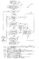
図7Aは、マルチスレッド・プロセッサ30内のイベント発生を処理する本発明の例示的な実施形態による方法220を示す流れ図である。方法220は、第1のスレッドの第1のイベントのイベント検出器188による検出でブロック222から開始する。図8は、ブロック222でイベント検出器188によって検出できる多数のイベント例224の図式表現である。図8で表されているイベントは、イベント224への応答の特性に応じて大まかにグループ分けされている。イベントの第1のグループは、検出後即座に、後述の方法でRESETイベント226と、マルチスレッド・プロセッサ30内のマルチスレッドにイベント検出器188により信号送出されるMACHINE CHECKイベント228を含み、すべてのスレッドが同時に同じイベント・ハンドラ67に入る。イベントの第2のグループは、それぞれ、イベントの信号が送出された特定のスレッドのマイクロ命令のリタイヤに関して報告されるFAULTイベント230、ASSISTイベント232、DOUBLE FAULTイベント234、SHUTDOWNイベント236、およびSMC(自己修正コード)イベント238を含む。特に、イベント検出器188は、フォルト情報がフォルト条件を示すマイクロ命令のリタイヤの後、第2のグループのイベントを検出する。第2のグループのイベントの検出は、関連イベントが発生したスレッドに対してのみイベント検出器188によってその信号が送られる。
【0067】
イベントの第3のグループは、INIT(短いリセット)イベント240、INTR(ローカル割り込み)イベント242、NMI(マスク不可能割り込み)イベント244、DATA BREAKPOINTイベント246、TRACE MESSAGEイベント248、およびA20M(アドレス・ラップアラウンド)イベント250を含む。第3グループのイベントは、アクセプト割り込みまたはアクセプト・トラップ・フロー・マーカを持つマイクロ命令のリタイヤに関して報告される。第3のグループのイベントの検出は、関連イベントが発生したスレッドに対してのみイベント検出器188によってその信号が送られる。
【0068】
イベントの第4グループは、SMI(システム管理割り込み)イベント250、STOP CLOCKイベント252、およびPREQ(プローブ要求)イベント254を含む。第4グループのイベントの信号が、マルチスレッド・プロセッサ30内に残っているすべてのスレッドへ送られ、複数のスレッドのうちのいずれか1つにより適切な割り込みフロー・マーカを持つマイクロ命令がリタイヤするときに報告される。第4のグループのイベントのどれかに応答して複数のスレッド間に同期がとられない。
【0069】
イベントの第5のグループは、例示的な実施形態に応じて、マルチスレッド・プロセッサ・アーキテクチャに固有のものであり、説明されている実施形態内で実施され、マルチスレッド・プロセッサ環境に特定の多数の考慮事項を扱う。イベントの第5のグループは、VIRTUAL NUKEイベント260、SYNCHRONIZATIONイベント262、およびSLEEPイベント264を含む。
【0070】
VIRTUAL NUKEイベント260は、(1)マルチスレッド・プロセッサ30内の第1のスレッドに保留イベントがあり(たとえば、上述のイベントのどれかが保留)、(2)第2のスレッドに保留イベントがなく(イベント260以外)、(3)共有リソース・フロー・マーカ184または同期フロー・マーカ186を持つマイクロ命令がリオーダ・バッファ162によってリタイヤされるときに第2のスレッドに関して登録されるイベントである。VIRTUAL NUKEイベント260は、フロー・マーカ184または186を持つリタイヤしたマイクロ命令の後のマイクロ命令で第2スレッドの実行を再開する仮想ヌーク・イベント・ハンドラを呼び出す。
【0071】
SYNCHRONIZATIONイベント262の信号は、マルチスレッド・プロセッサ30内の共有状態またはリソースを修正するために特定のスレッド(たとえば、第1のスレッド)が必要なときにマイクロコードによって送られる。この目的のために、マイクロコード・シーケンサ66は、同期マイクロ命令を第1のスレッドのフロー内に挿入し、デッドロック状況を避けるために、共有リソース・フロー・マーカ184と同期フロー・マーカ186の両方で「同期マイクロ命令」にマークをつける。SYCHRONIZATIONイベント262は、第1のスレッドの同期マイクロ命令のリタイヤ後と、関連する同期フロー・マーカ186を持つ第2のスレッドのマイクロ命令のリタイヤ後にのみ検出(または登録)される。SYNCHRONIZATIONイベント262は、マイクロコード一時レジスタ内に格納された命令ポインタで第1のスレッドの実行を再開する同期イベント・ハンドラの同期イベントを呼び出す効果を持つ。SYNCHRONIZATIONイベント262の処理に関する詳細を以下で取り上げる。第2のスレッドは、仮想NUKE 260を実行する。
【0072】
SLEEPイベント264は、関連スレッドをアクティブ状態からインアクティブ(またはスリープ)状態に遷移させるイベントである。インアクティブ・スレッドは、再び、適切なBREAKイベントによりインアクティブ状態からアクティブ状態に遷移させることができる。スレッドをアクティブ状態に遷移させて戻すBREAKイベントの性質は、スレッドをインアクティブ状態に遷移させたSLEEPイベント264に依存する。スレッドによりアクティブ状態に入る動作およびそこから出る動作について以下で詳述する。
【0073】
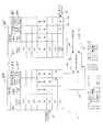
図9は、本発明の例示的な実施形態におけるイベントおよびクリア・ポイント(「ヌーク・ポイント」ともいう)検出を説明するために、後述のリオーダ・バッファ162内のリオーダ・テーブル180の例示的な内容を示すブロック図である。ブロック222のイベント検出器188による上記のイベントの1つを検出する動作が、マルチスレッド・プロセッサ30内の内部ソースからまたはプロセッサ30の外の外部ソースからイベント検出器188に伝達されるイベント266に応答して実行される。このようなイベント266の通信の例として、割り込みベクトルがある。それとは別に、イベントの発生を、リタイヤしその結果リタイヤ・ポインタ182によって識別される特定のスレッド(たとえば、スレッド1)のマイクロ命令に対するフォルト情報268によってイベント検出器188に伝達することができる。外部イベントについては、スレッドごとに1つの信号があることに注意されたい(たとえば、それぞれ信号266および267)。内部イベントについては、スレッドを含むリオーダ・バッファ162のエントリが、フォルトが位置によって関連付けられるスレッドを示す(たとえば、T0対T1)。イベントの検出後、イベント検出器188は、イベント情報レジスタ202内に特定のイベントに関するイベント情報(たとえば、イベント・タイプ、イベント・ソースなど)を格納し、さらに、保留イベント・レジスタ204内の関連スレッドの保留イベントを登録する。上述のように、関連するスレッドに対する保留イベント・レジスタ204内の保留イベントの登録では、レジスタ204内の、特定のイベントと関連するビットをセットする。さらに、関連するスレッドに対するイベント禁止レジスタ206内のビットのセットによりイベントが禁止されない場合に、適切なイベント検出信号211のアサートによりイベントが効果的に検出され、場合によっては、マイクロ命令は適切なフロー・マーカを含むことに注意されたい。
【0074】
図7Aに示されている流れ図に戻ると、ブロック222の第1のスレッドの第1のイベントの検出の後、イベント検出器188はブロック270で第1のスレッドのリタイヤを停止し、「ヌーク前」信号169をアサートする。ヌーク前信号169は、第1のスレッドが第2のスレッドの除外に対し命令パイプラインを支配するデッドロック状況を回避するためにアサートされる。特に、第2のスレッドを命令パイプラインへのアクセスから除外する場合、マルチスレッドのヌーク・オペレーションを開始するのに必要な第2のスレッドに関する条件は発生しない場合がある。ヌーク前信号169は、したがって、プロセッサのフロントエンドに伝播し、特に、メモリ実行ユニット42に伝播するため、イベントが検出された第1のスレッドを構成するマイクロ命令のプロセッサ・パイプラインが枯渇する。プロセッサ・パイプラインの枯渇は、単に、たとえば、メモリ実行ユニット42またはフロントエンドのその他のコンポーネントによって実行される命令のプリフェッチと自己修正コード(SMC)オペレーションを無効にすることにより実行できる。つまり、第1のスレッドのマイクロ命令のリタイヤを停止し、かつ/またはプロセッサ・パイプラインへの第1のスレッドによるマイクロ命令の供給を停止、あるいは実質的に低減することにより、第2のスレッドに対しプロセッサの優先度を与えるため、デッドロック状況の発生確率は低くなる。
【0075】
決定ボックス272で、第2のスレッドがマルチスレッド・プロセッサ30内でアクティブかどうか、それに応じてリオーダ・バッファ162によってリタイヤされるかどうかに関する決定が下される。第2のスレッドがアクティブでない場合、方法220は、直接、ブロック274に進み、そこで、「ヌーク・オペレーション」という第1のタイプのクリア・オペレーションが実行される。特定のスレッドがアクティブかインアクティブかの決定は、リタイヤ制御回路168によって保持されるアクティブなスレッド・ステート・マシン171に関して実行できる。ヌーク・オペレーションは、上述のように、状態のマルチスレッド・プロセッサ30の順序正しいフロントエンドおよび順序外れのバック・エンドの両方をクリアする効果を持つヌーク信号170のアサートから開始する。第1のスレッドのみがアクティブであるため、ヌーク・オペレーションの、マルチスレッド・プロセッサ30内に存在し残っている可能性のある他のスレッドに対する影響を考慮する必要がない。
【0076】
他方、第2のスレッドが決定ボックス272のマルチスレッド・プロセッサ30内でアクティブであると判断された場合、方法220は進行し、第2のスレッドのネガティブな結果を低減し、ヌーク・オペレーションを実行できる第2のスレッドに対しクリア・ポイント(またはヌーク・ポイント)を検出する一連のオペレーションを実行する。クリア・ポイントの検出後に実行されるヌーク・オペレーションは、ブロック274で実行されるオペレーションと同じであり、したがって、状態のマルチスレッド・プロセッサ30をクリアする(つまり、第1と第2の両方のスレッドの状態)。状態のクリア操作は、明細書の他のところで説明したマイクロ命令「ドレイン」オペレーションを含む。本出願で開示している例示的な実施形態では、クリア・ポイントの検出後に実行されるヌーク・オペレーションは、第1のスレッドに対し保持されている状態とマルチスレッド・プロセッサ30内の第2のスレッドに対し保持されている状態とを区別しない。代替実施形態では、クリア・ポイントの検出後に実行されるヌーク・オペレーションは、シングル・スレッドのみの状態をクリアするが(つまり、イベントが検出されたスレッド)、ただし、マルチスレッド・プロセッサ30内でリソース共有が著しい場合、またこのような共有されたリソースの動的な分割および分割解除により複数のスレッドを処理する場合であって、シングル・スレッドの状態のクリアは特に複雑である。ただし、この代替実施形態では、なおいっそう複雑なハードウェアが必要になる場合がある。
【0077】
決定ボックス272の肯定的決定の後、決定ボックス278で、さらに、第2のスレッドでイベントが発生したかどうかを判別する。このようなイベントは、上述のイベントのどれかを含むが、ただし、VIRTUAL NUKEイベント260は除く。この決定は再び、第2のスレッドのイベント信号266またはフォルト情報信号269に応答してイベント検出器188により行われる。第2のスレッドで生じたイベントに関する情報は、第2のスレッド専用のイベント情報レジスタ202の一部に格納され、イベント発生は保留イベント・レジスタ204内で登録される。
【0078】
第2のスレッドで独立にイベントが発生した場合、この方法は直接ブロック280に進み、そこで、マルチスレッド・ヌーク・オペレーションが実行され、状態のマルチスレッド・プロセッサ30をクリアする。それとは別に、第2のスレッドでイベントが発生しない場合、決定ボックス282で、第1のスレッドに対し発生した第1のイベントで、第1のイベントを処理するために共有状態、つまり共有リソースを修正する必要があるかどうかについて決定する。たとえば、上述のように第1のイベントがSYNCHRONIZATIONイベント262を含む場合、これは、第1のスレッドが共有状態リソースへのアクセスを必要とすることを示している。SYNCHRONIZATIONイベント262は、共有リソースと同期フロー・マーカ184および186の両方が関連付けられている第1のスレッドに対する同期マイクロ命令のリタイヤにより識別できる。図10は、図9に示されているのと似たブロック図であり、リオーダ・テーブル180の例示的な内容を示している。第1のスレッド(たとえばスレッド0)に割り当てられたテーブル180の部分は、リタイヤ・ポインタ182で参照されている同期マイクロ命令を含むことが示されている。同期マイクロ命令は、さらに、共有リソース・フロー・マーカ184および関連する同期フロー・マーカ186を備えることも示されている。図に示されている同期マイクロ命令のリタイヤは、SYNCHRONIZATIONイベント262の発生としてイベント検出器188によって登録される。
【0079】
第1のスレッド(たとえばスレッド0)の第1のイベントが共有状態またはリソースを修正しないと判断された場合、方法220は決定ボックス284に進み、そこで、第2のスレッド(たとえば、スレッド1)が、共有リソースのフロー・マーカ184が関連付けられるマイクロ命令をリタイヤするかどうかを決定する。図9を参照すると、スレッド1のリタイヤ・ポインタ182は、共有リソースのフロー・マーカ184および同期フロー・マーカ186の両方を持つマイクロ命令を参照することが示されている。この状況で、決定ボックス284で示されている条件が満たされ、したがって方法220はブロック280に進み、そこで、マルチスレッド・ヌーク・オペレーションが実行される。それとは別に、第2のスレッド(たとえば、スレッド1)のリタイヤ・ポインタ182が、共有リソースのフロー・マーカ184または同期フロー・マーカ186のいずれかを持つマイクロ命令を参照していない場合、この方法はブロック286に進み、そこで、リタイヤ・ポインタ182を進めることにより第2のスレッドのリタイヤが続行する。ブロック286から、方法220は決定ボックス278にループ・バックし、そこで、第2のスレッドでイベントが発生したかどうかを判別する。
【0080】
決定ボックス282で、第1のスレッド(たとえばスレッド0)の第1のイベントの処理で、共有リソースを修正が必要であるとと判断された場合、方法220は決定ボックス288に進み、そこで、第2のスレッド(たとえば、スレッド1)が、同期フロー・マーカ186が関連付けられるマイクロ命令をリタイヤしているかどうかが決定される。そうであれば、マルチスレッド・ヌーク・オペレーションがブロック280で実行される。実行されない場合、第2のスレッドに対するマイクロ命令のリタイヤはブロック286で、第2のスレッドに対してイベントが発生するか、第2のスレッドに対するリタイヤ・ポインタ182により同期フロー・マーカ186が関連付けられているマイクロ命令にインデックスを作成するまで続く。
【0081】
ブロック280でヌーク・オペレーションが開始した後、ブロック290で、マイクロコードにより実施され、マイクロコード・シーケンサ66から順序付けられる適切なイベント・ハンドラ67が関連イベントの処理へ進む。
【0082】
仮想ヌーク・イベント
上述のように、VIRTUAL NUKEイベント260は他のイベントと少し異なる方法で処理される。この目的のために、図7BはVIRTUAL NUKEイベント260を検出し、処理する、例示的な実施形態による方法291を示す流れ図である。方法291では、第2のスレッドのイベントは現在保留されていないと仮定している(つまり、第2のスレッドの保留レジスタに記録されていない)。
【0083】
方法291は、第1のスレッドの第1のイベントのイベント検出器188による検出でブロック292から開始する。このようなイベントは、図8を参照すると上述のイベントの1つとすることができる。
【0084】
ブロック293で、イベント検出器188は第1のスレッドのリタイヤを停止する。ブロック294で、イベント検出器188は、共有リソース・フロー・マーカ184または同期フロー・マーカのいずれかでマイクロ命令のリタイヤを検出する。ブロック295で、「仮想ヌーク」ハンドラがマイクロコード・シーケンサ66から呼び出される。「仮想ヌーク」イベント・ハンドラは、ブロック296で、ブロック294で上述のリタイヤしたマイクロ命令の後のマイクロ命令から第2のスレッドの実行を再開する。方法291は、ブロック297で終了する。
【0085】
ヌーク・オペレーション
図11Aは、少なくとも第1と第2のスレッドをサポートするマルチスレッド・プロセッサ内でクリア(またはヌーク)動作を実行する例示的な実施形態による方法300を示す流れ図である。方法300は、イベントの発生および検出に応答して、イベント検出器188によりヌーク信号170のアサートでブロック302から開始する。ヌーク信号170は、マルチスレッド・プロセッサ30内の多数の機能ユニットに伝達され、そのアサートおよびデアサートにより、状態のクリアと機能ユニットの構成の準備のための活動を実行するウィンドウが定義される。図12は、クロック信号304の立ち上がりエッジと同期して発生するヌーク信号170のアサートを示すタイミング図である。
【0086】
ブロック303で、アクティブなスレッド・ステート・マシンが評価される。
【0087】
ブロック306で、第1のスレッドと第2のスレッドの両方に対して、イベントが発生したマイクロ命令がリタイヤしているかどうかを示す順序番号および最後のマクロ命令信号が割り当ておよび空きリスト管理ロジック122、およびプロセッサ30の順序正しいフロントエンド内のマクロ命令とマイクロ命令のポインタ情報を追跡する追跡分岐予測ユニット(TBPU)内の構造である(したがって、TDE60の一部である)TBITに伝達される。TBITでは、この情報を使用して、イベントに関する情報をラッチする(たとえば、マイクロ命令およびマクロ命令のポインタ)。
【0088】
ブロック308で、イベント検出器188は第1と第2のスレッドのそれぞれに対しイベント・ベクトルを構成し、マイクロコード・シーケンサ66に伝播する。とりわけ、各イベント・ベクトルは、(1)ヌーク・ポインタ(またはクリア・ポイント)が特定されたときにリタイヤした物理リオーダ・バッファの位置(つまり、ヌーク・ポイントが識別されたときの各リタイヤ・ポインタ182の値)、(2)検出されたイベントを処理するためイベント・ハンドラ67を構成するマイクロコードが配置されているマイクロコード・シーケンサ66内の位置を識別するイベント・ハンドラ識別子、および(3)第1と第2のスレッドのいずれかを識別するスレッド識別子、および(4)他のスレッドについて呼び出されたイベント・ハンドラに関してイベント・ハンドラ67の優先度を決定するスレッド優先度ビットを識別する情報を含む。
【0089】
ブロック310で、割り当ておよび空きリスト管理ロジック122は、ブロック306で伝達された順序番号を利用して、シャドウ・エイリアス・テーブル(シャドウRAT)を、ヌーク・ポイントが検出された位置へ進め、ブロック312で、一次レジスタ・エイリアス・テーブル120の状態がシャドウ・レジスタ・エイリアス・テーブルから復元される。
【0090】
ブロック314で、割り当ておよび空きリスト管理ロジック122は、レジスタ番号(または「マーブル」)を空きリスト・マネージャ134から回復し、回復されたレジスタ番号をトラッシュ・ヒープ配列132に割り当て、そこでレジスタ番号を再び割り当てることができる。さらに割り当ておよび空きリスト管理ロジック122は、すべての適切なレジスタ番号が空きリスト・マネージャ134から回復されたときに「回復」信号(図に示されていない)をアサートする。ヌーク信号170は、この「回復」信号が割り当ておよび空きリスト管理ロジック122から受け取るまで、アサート状態に保持される。
【0091】
ブロック316で、第1および第2のスレッドの両方に対するすべての「シニア」ストア(つまり、リタイヤされたが、まだメモリを更新していないストア)が、ストア・コミット・ロジック(図に示されていない)を使用してメモリ順序バッファから排出される。
【0092】
ブロック320で、イベント検出器188が、図12に示されているように、クロック信号304の立ち上がりエッジでヌーク信号170をデアサートする。ヌーク信号170は、クロック信号304の最低限3クロック・サイクルの間アサート状態に保持されていたことに注意されたい。ただし、割り当ておよび空きリスト管理ロジック122からの「回復」信号がヌーク信号170のアサートに続いてクロック信号304の第1の2クロック・サイクル以内にアサートされない場合、イベント検出器188は図の3クロック・サイクルを超えてヌーク信号170のアサートを延長する。ヌーク信号170は、一実施形態では、十分に長い時時間保持され(たとえば、3クロック・サイクルの間)、上述のブロック303、306、および308を完了させる。ヌーク信号170は、ブロック310、312、314、および316を完了させるために追加サイクルの間保持する必要があることがある。この目的のために、メモリ順序バッファは、「排出されたストア・バッファ」信号をアサートし、ヌーク信号のアサートを延長する。
【0093】
ブロック322で、マルチスレッド・プロセッサ30内のマイクロコード・シーケンサ66およびその他の機能ユニットはアクティブなスレッド・ステート・マシン171によって保持される「アクティブ・ビット」を調べて、第1および第2のスレッドがそれぞれ、イベント発生後、アクティブ状態にあるのかインアクティブ状態にあるのかを判別する。より具体的には、アクティブなスレッド・ステート・マシン171は、関連スレッドがアクティブ状態またはインアクティブ(スリープ)状態であるかを示すマルチスレッド・プロセッサ30内に残っているスレッドごとにそれぞれのビット指標を保持する。イベントがイベント検出器188によって検出され、このイベントに応答してイベント検出器188がヌーク信号170をアサートしているが、このイベントは、SLEEPイベント264またはアクティブ状態とインアクティブ状態との間で第1または第2のスレッドを遷移するBREAKイベントのいずれかを含むことができる。図12の324で示されているように、アクティブなスレッド・ステート・マシン171がヌーク信号170のアサートが行われている間に評価され、それに応じて「アクティブ・ビット」の状態がヌーク信号170のデアサート後有効とみなされる。
【0094】
決定ボックス326で、アクティブなスレッド・ステート・マシン171のアクティブ・ビットを調べた機能ユニットのそれぞれが、第1および第2のスレッドがアクティブかどうかを判別する。両方のスレッドがアクティブ・ビットの状態に基づいてアクティブであると判別された場合、方法300はブロック328に進み、そこで、それぞれの機能ユニットは第1と第2のアクティブ・スレッドの両方をサポートし、処理するように構成される。たとえば、さまざまな機能ユニット内に用意される格納およびバッファリング機能は、ストレージ配列内の特定のエントリ・セット(範囲)に限られた第2のポインタ、つまり第2のポインタ・セットをアクティブにすることにより論理的に分割することができる。さらに、2つのスレッドがアクティブな場合に、MT固有のサポートをアクティブにできる。たとえば、マクロコード・シーケンサと関連付けられたスレッド選択ロジックが、アクティブなスレッド・ステート・マシン171の出力に基づいて、「ピンポン」方式により第1のスレッド(たとえば、T0)から、第2のスレッド(たとえば、T1)から、または第1と第2のスレッド(たとえば、T0とT1)からスレッドを順序付けることができる。さらに、ローカライズされたクロック・ゲート機能を、アクティブなスレッド・ステート・マシンのビット出力に基づいて実行できる。他の実施形態では、プロセッサ内の任意の数のステート・マシンが、アクティブなスレッド・ステート・マシンの出力に基づいてその動作、または変化状態を修正できる。ブロック330で、マイクロコード・シーケンサ66は、第1と第2のスレッドの両方のマイクロ命令の順序付けに進む。
【0095】
それとは別に、決定ボックス326で、第1と第2のスレッドのうち1つだけアクティブであるか、または両方のスレッドがインアクティブであると判断された場合、機能ユニットのそれぞれが、ブロック332で単一のアクティブ・スレッドのみをサポートし処理するように構成され、何らかのMT固有サポートをインアクティブにできる。アクティブなスレッドがない場合、機能ユニットはデフォルト設定として、単一のアクティブ・スレッドをサポートするように構成される。複数のスレッドをサポートするように機能ユニットがすでに構成されている(たとえば、論理パーティション分割されている)場合、他のスレッドをサポートするために利用されるポインタを無効にすることができ、残りのポインタによって参照されているデータ配列内のエントリ・セットを、無効にされたポインタによってすでに参照されているエントリを含むように拡張できる。このようにして、他のスレッドにすでに割り当てられているデータ・エントリを単一のアクティブ・スレッドで使用できるようにする。他のスレッドがインアクティブのときに単一のアクティブ・スレッドで利用できるリソースを増やすことにより、他のスレッドもマルチスレッド・プロセッサ30内でサポートされている場合にそのパフォーマンスに関して単一の残りのスレッドのパフォーマンスを高めることができる。
【0096】
ブロック334で、マイクロコード・シーケンサ66は、インアクティブのスレッド、つまりインアクティブ・スレッドについてイベント・ベクトルを無視し、可能なアクティブ・スレッドに対してのみマイクロ命令を順序付ける。アクティブなスレッドがない場合、マイクロコード・シーケンサ66は、すべてのスレッドに対するイベント・ベクトルを無視する。
【0097】
ヌーク信号170のデアサート(ヌーク・オペレーションの終わりを示す)の後さまざまな機能ユニットにより調査できるアクティブなスレッド・ステート・マシン171で保持されるアクティブ・ビットを与えることにより、都合のよい一括集中の指標を用意し、これに従って、ヌーク・オペレーションの完了後にマルチスレッド・プロセッサ30内の正しい個数のアクティブ・スレッドをサポートするように構成できる。
【0098】
図11Bは、例示的な構成ロジック329を示すブロック図で、機能ユニット331と関連付けられており、マルチスレッド・プロセッサ内の1つまたは複数のアクティブ・スレッドをサポートするように機能ユニット331を構成する動作をする。機能ユニット331は、上述の機能ユニットのいずれか1つ、または当業者であればプロセッサに含められることを理解できる機能ユニットとすることができる。機能ユニット331は、構成ロジック329によって構成される格納およびロジック・コンポーネントの両方を備えることが示されている。たとえば、格納コンポーネントはレジスタの集まりを備える。これらのレジスタはそれぞれ、複数スレッドがアクティブなときに(つまり、プロセッサがMTモードで動作しているときに)これらのスレッドの特定の1つについてマイクロ命令またはデータを格納するように割り当てることができる。したがって、図11Bで示されているように格納コンポーネントは、第1および第2のスレッド(たとえば、T0およびT1)をサポートするように論理的に分割される。もちろん、格納コンポーネントは、任意の数のアクティブ・スレッドをサポートするように分割できる。
【0099】
ロジック・コンポーネントは、プロセッサ内のマルチスレッド・オペレーションを特にサポートするMTロジックを含むことが示されている(つまり、MTモード)。
【0100】
構成ロジック329は、ポインタ値333を保持することが示されており、これは機能ユニット331の格納コンポーネントに出力される。例示的な一実施形態では、これらのポインタ値333を使用して、格納コンポーネントを論理的に分割する。たとえば、読み書きポインタ値の個別のペアをアクティブ・スレッドごとに生成することが可能である。各スレッドのポインタ値の上限および下限は、アクティブ・スレッドの個数に応じて、構成ロジック329によって決定される。たとえば、特定のスレッドに対するポインタ値の集合によって示すことができるレジスタの範囲を拡大し、その他のスレッドがインアクティブになった場合に、他のスレッドにすでに割り当てられているレジスタをカバーできる。
【0101】
構成ロジック329はさらに、MTサポート有効化指標335も備え、これは、機能ユニットのロジック・コンポーネントに出力され、機能ロジック331のMTサポート・ロジックを有効または無効にする。
【0102】
アクティブ・ビット327は、アクティブなスレッド・ステート・マシン174によって出力され、入力を構成ロジックに送り、構成ロジック329では、アクティブ・ビット327を使用して、値の適切なポイント333を生成し、適切なMTサポート有効化出力を出す。
【0103】
イベント・ハンドラによる排他的アクセス
いくつかのイベント・ハンドラ(たとえば、ページングと同期イベントを処理するハンドラ)では、共有リソースを利用し、共有リソースを修正するために、マルチスレッド・プロセッサ30への排他的アクセスが必要である。したがって、マイクロコード・シーケンサ66は、排他的アクセス・ステート・マシン69を実装し、さらにこれらのイベントハンドラのいずれかがこのような排他的アクセスを必要とする第1および第2のスレッドに対するイベント・ハンドラに対する排他的アクセスを可能にする。排他的アクセス・ステート・マシン69は、複数のスレッドがマルチスレッド・プロセッサ30内でアクティブなときにのみ参照できる。フロー・マーカは、排他的アクセス機能を持つイベント・ハンドラと関連付けられているが、スレッドのフロー内に挿入され、イベント・ハンドラを含む排他的コードの終わりをマーク付けする。すべてのスレッドについて排他的アクセスが完了すると、マイクロコード・シーケンサ66はマイクロ命令の通常発行を再開する。
【0104】
図13は、マルチスレッド・プロセッサ30内のイベント・ハンドラ67への排他的アクセスを可能にする例示的な実施形態による方法400を示す流れ図である。方法400は、イベント検出器188から第1および第2のそれぞれのスレッドについて第1および第2のイベント・ベクトルのマイクロコード・シーケンサ66をマイクロコードで受け取ったことでブロック402から開始する。上述のように、第1および第2のイベント・ベクトルのそれぞれで、各イベント・ハンドラ67を識別する。
【0105】
決定ボックス403で、複数のスレッドがアクティブかどうかを判別する。この判別は、アクティブなスレッド・ステート・マシン171に関して、マイクロ・コード・シーケンサにより行う。そうでなければ、方法400はブロック434に進む。
【0106】
そうであれば、方法400はブロック404に進む。決定ボックス404で、マイクロコード・シーケンサ66は、第1または第2のイベント・ハンドラ67のいずれかが共有リソースへの排他的アクセスを必要とするか、共有状態を修正するかに関する決定を行う。そうであれば、ブロック406で、マイクロコード・シーケンサ66は、排他的アクセス・ステート・マシン69を実装し、第1および第2のイベント・ハンドラ67のそれぞれへの排他的アクセスを提供する。図14は、排他的アクセス・ステート・マシン69の実施形態による動作を示す状態図である。ステート・マシン69は、5つの状態を含むことが示されている。第1の状態408で、第1および第2のスレッドに対するマイクロコードは、マイクロコード・シーケンサ66によって両方とも発行される。排他的アクセス・イベント・ハンドラを必要とするイベントに応答してヌーク・オペレーション410が実行された後、ステート・マシン69は第2の状態412に遷移し、第1のスレッドのイベントと関連する第1のイベント・ハンドラ67(つまり、マイクロ命令)が発行される。第1のイベント・ハンドラ67を構成するすべてのマイクロ命令の順序付けに続き、またこのようなマイクロ命令によって指示されたすべてのオペレーションの完了の後、マイクロコード・シーケンサ66は、414で停止マイクロ命令(たとえば、関連する停止フロー・マーカを持つマイクロ命令)を発行して、ステート・マシン69を第2の状態412から第1のスレッドのマイクロ命令の発行が停止している第3の状態416に遷移させる。418で、414で発行された停止マイクロ命令がリオーダ・バッファ162からリタイヤされ、それにより、ステート・マシン69は第3の状態416から第2のスレッドのイベントと関連してマイクロコード・シーケンサ66が第2のイベント・ハンドラ67を発行する第4の状態420に遷移する。第2のイベント・ハンドラ67を構成するすべてのマイクロ命令の順序付けに続き、またこのようなマイクロ命令によって指示されたすべてのオペレーションの完了の後、マイクロコード・シーケンサ66は、さらに422で停止マイクロ命令を発行し、ステート・マシン69を第4の状態から第2のイベント・ハンドラ67が停止している第5の状態424に遷移する。426で、422で発行された停止マイクロ命令はリオーダ・バッファ162からリタイヤされ、それにより、ステート・マシン69は第5の状態424から第1の状態408に戻る。
【0107】
ブロック432で、第1と第2の両方のスレッドに対するマイクロ命令の通常の順序付けおよび発行が、両スレッドともアクティブであると想定して再開される。
【0108】
それとは別に、決定ボックス404で、第1または第2のイベント・ハンドラのいずれもプロセッサ30の共有リソースまたは状態への排他的アクセスを必要としないと判断された場合、この方法はブロック434に進み、そこで、マイクロコード・シーケンサ66が第1と第2のイベント・ハンドラ67を非排他的インタリーブ方式で構成するようにマイクロコードを順序付ける。
【0109】
アクティブなスレッド・ステート・マシン(171)
図15は、アクティブなスレッド・ステート・マシン171によって占有される例示的な実施形態による状態を示し、さらに、アクティブなスレッド・ステート・マシン171にさまざまな状態間の遷移を行わせる例示的な実施形態による遷移イベントを示す状態図500である。
【0110】
アクティブなスレッド・ステート・マシン171は、4つの状態のうちの1つ、つまり、シングル・スレッド0(ST0)状態502、シングル・スレッド1(ST1)状態504、マルチスレッド(MT)状態506、およびゼロ・スレッド(ZT)状態508のうちの1つにあることが示されている。アクティブなスレッド・ステート・マシン171は、セットされたときに、関連するスレッドをアクティブであると識別し、リセットされたときに、関連するスレッドをインアクティブまたはスリープ状態であると識別する各スレッドに対する単一のアクティブ・ビットを保持する。
【0111】
4つの状態502〜508の間の遷移は、それぞれのイベントが第1または第2のスレッドに関連するイベントのペアによってトリガされる。状態図500では、多数のイベント・タイプが、状態間の遷移にかかわるものとして示されている。特に、SLEEPイベントは、スレッドをインアクティブにするイベントである。BREAKイベントは、特定のスレッドに対し発生した場合に、スレッドをインアクティブ状態からアクティブ状態に遷移させるイベントである。特定のイベントがBREAKイベントとして適格であるかどうかはスレッドをインアクティブにしたSLEEPイベントによる。特に、特定のSLEEPイベントの結果としてインアクティブになった後、いくつかのイベントのみが、スレッドをアクティブにできる。NUKEイベントは、特定のスレッドに対し発生した場合に、上述のようにヌーク・オペレーションを実行するイベントである。図8を参照して上述したすべてのイベントは、ヌーク・イベントを含む可能性がある。最後に、状態図500内には、特定のスレッドに関する「イベントなし」発生が、状態遷移を引き起こす他のスレッドに関するイベント発生と組合せて存在しうる条件であるとして示されている。
【0112】
一実施形態では、SLEEPイベントが特定のスレッドについて信号送出され、そのスレッドのBREAKイベントが保留になっている場合、BREAKイベントは即座に処理される(たとえば、スレッドは、スリープ状態にならず、後で目覚めてBREAKイベントを処理する)。逆も真である場合があり、特定のイベントについてBREAKイベントの信号が送られ、SLEEPイベントが保留であり、それ以降、BREAKイベントが処理される。
【0113】
イベント検出器188によってヌーク信号170がアサートされた後、図12の324で示されているように、アクティブなスレッド・ステート・マシン171が評価される。ヌーク信号170のデアサート後、マルチスレッド・プロセッサ30内のすべての機能ユニットが、アクティブなスレッド・ステート・マシン171によって保持されているアクティブ・ビットに基づき構成される。特に、チェッカ、リプレイ、およびリタイヤ・ユニット(CRU)160はアクティブ・ビットに基づして生成された信号を影響のあるすべての機能ユニットに伝播し、マルチスレッド・プロセッサ内に残っているスレッドの数とそれらのスレッドのうちどれがアクティブかを機能ユニットに示す。ヌーク信号170のアサートに続いて、機能ユニットの構成(たとえば、パーティション分割または解放)は、通常、クロック信号304の1クロック・サイクルで完了する。
【0114】
スレッドの出入り
本発明では、マルチスレッド・プロセッサ30内のスレッドが出入りする(たとえば、アクティブになったりインアクティブになったりするなど)例示的なメカニズムを提案するが、この提案によれば、そのような出入りのメカニズムが実行されているスレッドの数に関係なく一様な順序で実行され、マルチスレッド・プロセッサ30内にアクティブなまたは実行中のスレッドがないときにさまざまな機能ユニットへのクロック信号を順序正しく停止できる。
【0115】
状態図500を参照して上述したように、スレッドに入る(またはアクティブにする)動作は、現在インアクティブのスレッドに対しBREAKイベントを検出したことに応答して実行される。特定のインアクティブ・スレッドに対するBREAKイベント定義は、関連するスレッドがインアクティブである理由によって決まる。スレッドから出る動作は、現在アクティブなスレッドに対するSLEEPイベントに応答して実行される。SLEEPイベントの例としては、アクティブ・スレッドに含まれる停止(HLT)命令の実行、SHUTDOWNまたはERROR SHUTDOWN条件の検出、またはアクティブ・スレッドに関する「SIPI待機」(プロセッサ間割り込みの起動)がある。
【0116】
図16Aは、アクティブ・スレッドのSLEEPイベントが検出された後アクティブ・スレッドを終了する本発明の例示的な実施形態による方法600を示す流れ図である。方法600は、ブロック602から開始し、アクティブ・スレッドに必要なすべての状態を保存し、アクティブ・スレッドに対してすでにマイクロ命令に割り当てられているレジスタ・ファイル124内のレジスタ・エントリを解放する。例にすぎないが、レジスタ・ファイル124内の128個のレジスタ・エントリのうち、アクティブ・スレッドのマイクロ命令にすでに割り当てられている28個のエントリが解放される。アクティブ・スレッドに対する解放されたレジスタの内容は、「スクラッチ・パッド」に保存され、これは、レジスタ配列または、マルチスレッド・プロセッサ30内の制御レジスタ・バスに結合されているランダム・アクセス・メモリ(RAM)を含むことができる。
【0117】
レジスタ・ファイル124内のレジスタ・エントリの解放は、アクティブ・スレッドに対するSTOPCLK、HALT(HLT)、またはSHUTDOWNイベントを検出したことに応答してマイクロコード・シーケンサ66によって発行される解放マイクロコード・シーケンスによって実行できる。解放マイクロコード・シーケンスは、空きリスト・マネージャ134内のレジスタ・ファイル・エントリの記録を削除(または無効化)し、トラッシュ・ヒープ配列132内のレジスタ・ファイル・エントリの記録を作成(または有効化)する動作をする。つまり、解放レジスタ・ファイル・エントリの記録は、解放されたマイクロコード・シーケンスにより空きリスト・マネージャ134からトラッシュ・ヒープ配列132に転送される。
【0118】
図16Bは、ブロック602で実行できるオペレーションの例示的な実施形態の図式表現である。たとえば、第1のスレッド(たとえばT0)にすでに割り当てられているレジスタ・ファイル124内の第1のレジスタ・セットの内容は、スクラッチ・パッドに転送されることが示されている。さらに、状態の保存で実行できる追加オペレーションには、既存のスレッドのアーキテクチャ・レジスタの内容をスクラッチ・パッドに格納する動作および第1のスレッドを抜けたときに第1のスレッドに割り当てられたマイクロコード一時レジスタの内容をスクラッチ・パッドに格納する動作も含まれる。その後、スレッドを出て空になったレジスタは、他のスレッド(たとえばT1)への再割り当てに使用できる。
【0119】
特定のスレッド(たとえば、T0)に再度入った後、このスレッドに割り当てられたレジスタの内容は図16Bの破線で示されているように、スクラッチ・パッドから復元できることは理解されるであろう。
【0120】
ブロック604で、出るスレッドに対するスレッド固有の「フェンス・マイクロ命令」が出るスレッドのマイクロ命令フロー内に挿入され、スレッドと関連する残りの保留メモリ・アクセスをメモリ順序バッファ48、さまざまなキャッシュ、およびプロセッサ・バスから排出する。このオペレーションは、これらのブロックすべてが完了するまでリタイヤしない。
【0121】
これらの実行ユニット20は、マイクロ命令を比較的高速に実行するので、実行ユニット入力に追加された新規のすべてのマイクロ命令は、SLEEPイベントの検出に応答してヌーク信号のアサートでクリアされる。上述のように、ヌーク信号170は、十分な期間保持され(たとえば、3クロック・サイクル)、ヌーク信号170のアサートの前に実行ユニット70に入ったマイクロ命令がそこから現れる。これらのマイクロ命令は、実行ユニット70から出てくるので、クリアされ、書き戻しが取り消される。
【0122】
ブロック606で、イベント検出器188内に保持されている解放レジスタ208がセットされ、マイクロコード・シーケンサ66によって生成されて解放レジスタの状態を設定する値を書き戻すマイクロ命令により既存のスレッドがインアクティブ(またはスリープ)状態に入っていることを示す。
【0123】
ブロック608で、出るスレッドのイベント禁止レジスタ206がセットされ、マイクロコード・シーケンサ66によって発行された制御レジスタ書き込みマイクロ命令によって出るスレッドの非ブレーク・イベントが禁止される。制御レジスタ・マイクロ命令として指示されている、出るスレッドに対するイベント禁止レジスタをセットする動作は、処理されるスリープ・イベントのタイプによって異なる。上述のように、インアクティブ状態への遷移をトリガしたSLEEPイベントに応じて、いくつかのイベントのみがインアクティブ・スレッドに関してブレーク・イベントとして適格である。イベントが特定のインアクティブ・スレッドに対するブレーク・イベントとして適格かどうかを判別する操作は、インアクティブ・スレッドに対するイベント禁止レジスタ206の状態を特に参照して行われる。
【0124】
ブロック612で、出るスレッドのスリープ・イベントの信号は、特別なマイクロ命令の書き戻しフォルト情報フィールド内にスリープ・イベント・エンコーディングを置く特別マイクロ命令を使用して送出する。
【0125】
図17は、インアクティブ・スレッドに対するBREAKイベントが検出された後インアクティブ・スレッドからアクティブ状態に入る例示的な実施形態による方法700を示す流れ図である。方法700は、インアクティブ・スレッドに関してBREAKイベントとして適格であるまたは適格でないイベントに対しイベント発生を検出したことで702から開始する。決定ボックス703で、関連するイベントについてイベント検出ロジック185により判別し、イベントがインアクティブ・スレッドのBREAKイベントとして適格であるかどうかを判別する。この目的のために、イベント検出ロジック185は、イベント検出器188のレジスタ200内のイベント禁止レジスタ206を調べる。関連するイベント・タイプがインアクティブ・スレッドに関して禁止されているBREAKイベントとして示されていない場合に、方法700はブロック704に進み、そこで、必要に応じてクロックをオンにし、イベントの信号を通常どおり送信し(他のスレッドのヌーク可能ポイントを待つ)、ハンドラは任意のイベントで呼び出される。イベント・ハンドラは、スレッドのスリープ状態をチェックし、もし設定されていれば、ブロック706のマイクロコード状態の復元に進む。イベント・ハンドラ67では、解放レジスタ208にアクセスしてスレッドのインアクティブ状態を確認する。
【0126】
より具体的には、イベント・ハンドラ67は、保存されているすべてのレジスタ状態、禁止レジスタ状態、および命令ポインタ情報を復元することにより、入るスレッドのマイクロコード状態の復元に進む。
【0127】
ブロック706のマイクロコード状態の復元の後、方法700はブロック708に進み、そこで、入るスレッドについてアーキテクチャ状態が復元される。ブロック710で、入るスレッドのイベント禁止レジスタ206が、マイクロコード・シーケンサ66から発行された適切なマイクロ命令によりリセットまたはクリアされる。ブロック712で、イベント・ハンドラ67は、BREAKイベントの処理に進む。このときに、イベント・ハンドラ67を構成するマイクロコードがマルチスレッド・プロセッサ30内で実行され、イベント発生に応答して一連のオペレーションを実行する。ブロック716で、入るスレッドについてプロセッサ30内で命令フェッチ・オペレーションを再開する。方法700は、ブロック718で終了する。
【0128】
クロック制御ロジック
マルチスレッド・プロセッサ30内の消費電力と放熱を低減するために、ある条件のもとでは、プロセッサ30内で少なくともいくつかのクロック信号を停止またはサスペンドすることが望ましい。図18は、上述の例示的なプロセッサ30などのマルチスレッド・プロセッサ内の選択されたクロック信号を停止または保留する例示的な実施形態による方法800を示す流れ図である。本明細書の目的のために、プロセッサ内のクロック信号のサスペンドまたは停止する操作を引用した場合、プロセッサ30内のクロック信号、または信号をサスペンドまたは停止する多数の手法があることを意味する。たとえば、プロセッサ30内の位相ロック・ループ(PLL)をサスペンドしたり、クロック・スパインにそったコア・クロック信号の分配を禁止したり、クロック・スパインを介したプロセッサ内の個別機能ユニットへのクロック信号の分配をゲートしたりその他の方法で禁止したりできる。一実施形態では、後者の状況を説明しており、機能ユニットごとに機能ユニット上でプロセッサ30内の機能ユニットへの内部クロック信号の供給がサスペンドまたは停止される。したがって、他の機能ユニットに関してゲートしながら内部クロック信号をいくつかの機能ユニットに供給することができる。このような配置は、米国特許第5655127号のシングル・スレッド・マイクロプロセッサの背景で説明されている。
【0129】
図18に示されている方法800は、一実施形態では、プロセッサ30のバス・インタフェース・ユニット32に組み込まれているクロック制御ロジック35で実行できる。代替実施形態では、クロック制御ロジック35は、もちろん、プロセッサ30と別のところに配置できる。図19Aおよび19Bは、それぞれ、クロック制御ロジック例35に関する詳細を示すブロック図および概略図である。
【0130】
まず図19Aを見ると、クロック制御ロジック35が3つの一次入力、つまり(1)アクティブなスレッド・ステート・マシン174を介して出力されるアクティブ・ビット820(たとえば、T0_ACTIVEおよびT1_ACTIVE)、(2)イベント検出器188によって出力されるイベント検出信号211、および(3)バス上のスヌープ可能アクセスを検出し、信号882をアサートするバス・インタフェース・ユニット32によって出力されるスヌープ制御信号822を受け取るように示されている。クロック制御ロジック35は、これらの入力を使用して、停止クロック信号826を発生し、この信号により、プロセッサ30内のいくつかの機能ユニットのクロック動作を抑制または禁止する。
【0131】
図19Bは、入力211、820、および822を利用して、クロック停止信号826を出力する例示的な組合せロジックを示す概略図である。特に、イベント検出器信号211が入力をORゲート822に送り、これにより、入力をさらにORゲート824に送る。アクティブ・ビット820およびスヌープ制御信号822は、NORゲート824への入力となり、これらの入力のORをとって、クロック停止信号826を出力する。
【0132】
特に図18を参照すると、方法800は、決定ボックス802から開始し、スレッド(たとえば、第1と第2のスレッド)がマルチスレッド・プロセッサ30内でアクティブかどうかを判別する。この判別は、図19Bでアクティブ・ビット820をORゲート824に出力することにより反映される。例示的な実施形態では判別が2つのスレッドに関して満たされることを示しているが、この判別は、マルチスレッド・プロセッサ内でサポートされている任意の数のスレッドに関して行えることは容易に理解されるであろう。
【0133】
決定ボックス802での否定的な決定に続いて、方法800は決定ボックス804に進み、そこで、禁止されていないイベントがマルチスレッド・プロセッサ内でサポートされている任意のスレッドについて保留されているかどうかを判別する。再び、例示的な実施形態では、これは、イベントが第1または第2のスレッドに対し保留になっているかどうかの判別を含む。この判別は、図19Bに示されているように、イベント検出信号211をORゲート822に入力することにより表される。
【0134】
決定ボックス804での否定的な決定に続いて、スヌープ(たとえば、バス・スヌープ、SNCスヌープ、またはその他のスヌープ)がプロセッサ・バスで処理されているかどうかの判別を決定ボックス806で行う。本発明の例示的な実施形態では、この判定は、スヌープ制御信号822をORゲート824に入力することで実行される。
【0135】
決定ボックス806の否定的な決定に続いて、方法800はブロック808に進み、そこで、選択された機能ユニットへの内部クロック信号が停止または抑制される。特に、バス保留ロジックおよびバス・アクセス・ロジックへのクロック信号は、サスペンドまたは停止されないが、それは、バス・インタフェース・ユニット32でシステム・バス上で発せられるBREAKイベントまたはスヌープ(たとえば、ピン・イベント)を検出し、このようなBREAKイベントに応答して機能ユニットへのクロック供給を再開するからである。機能ユニットへの内部クロック信号の抑制は、クロック停止信号826のアサートにより実行され、所定の機能ユニットへのクロック信号のゲート動作が行われる。
【0136】
ブロック808の完了後、方法800は決定ボックス802にループ・バックする。決定ボックス802での判別の後、804および806は、引き続きループすることができる。
【0137】
決定ボックス802、804、および806のいずれか1つで肯定的な決定を行った後、方法800はブロック810に分岐し、そこで、いくつかの機能ユニットへのクロック信号がゲートされた場合に、これらの内部クロック信号が再びアクティブにされる。それとは別に、クロック信号がすでにアクティブであれば、これらのクロック信号がアクティブ状態に保持される。
【0138】
ブロック810がブレーク・イベントに応答して実行される場合(たとえば、決定ボックス804の肯定的決定の後)、ヌーク信号のアサート時に、アクティブ・スレッドの個数に基づいて、上述の方法によりマイクロプロセッサ内の機能ユニットをアクティブに分割することができる。たとえば、2つまたはそれ以上のスレッドを持つマルチスレッド・プロセッサ30では、これらのスレッドのうちいくつかをインアクティブにできるが、その場合、機能ユニットはインアクティブ・スレッドに対応できるように分割されない。
【0139】
ブロック810で完了した後、方法800は、再び、決定ボックス802にループ・バックし、決定ボックス802、804、および806で表される決定をさらに繰り返す動作を開始する。
【0140】
こうして、マルチスレッド・プロセッサ内の複数のスレッドに入り、出る方法と装置について説明した。本発明は、特定の例示的な実施形態を参照しながら説明したが、本発明の広い範囲と精神を逸脱することなく、これらの実施形態に各種の修正および変更を加えられることは明白であろう。したがって、明細書および図面は、制限のためではなく、説明するために用意されていると見なすべきである。
【図面の簡単な説明】
【図1】 マルチスレッド・サポートのあるプロセッサのパイプラインの一実施形態を示すブロック図である。
【図2】 汎用マルチスレッド・マイクロプロセッサの形式のプロセッサの例示的な実施形態を示すブロック図である。
【図3】 例示的なマルチスレッド・プロセッサの選択したコンポーネントを示すブロック図であり、特に、複数のスレッドに対応するように論理パーティションが設定されているバッファリング(または記憶領域)機能を提供するさまざまな機能ユニットを示す図である。
【図4】 一実施形態による順序の狂っているクラスタを示すブロック図である。
【図5】 レジスタ・エイリアス・テーブルおよびレジスタ・ファイルの図式表現であり、一実施形態内で使用される。
【図6A】 一実施形態による、マルチスレッド・プロセッサ内の複数のスレッドを処理するように論理パーティションが設定されているリオーダ・バッファに関する詳細を示すブロック図である。
【図6B】 一実施形態による保留イベント・レジスタとイベント禁止レジスタの図式表現である。
【図7A】 マルチスレッド・プロセッサ内のイベントを処理する一実施形態による方法を示す流れ図である。
【図7B】 マルチスレッド・プロセッサ内の「仮想ヌーク」イベントを処理する一実施形態による方法を示す流れ図である。
【図8】 マルチスレッド・プロセッサ内に実装された、一実施形態による、イベント検出装置により検出できる多数の例示的なイベントの図式表現である。
【図9および図10】 図6Aに示されているような、例示的なリオーダ・バッファ内のリオーダ・テーブルの例示的な内容を示すそれぞれのブロック図である。
【図11A】 少なくとも第1と第2のスレッドをサポートするマルチスレッド・プロセッサ内でクリア(またはヌーク)動作を実行する例示的な実施形態による方法を示す流れ図である。
【図11B】 アクティブなスレッド・ステート・マシンの出力に応じて機能ユニットを構成するように動作する例示的な一実施形態による構成ロジックを示すブロック図である。
【図12】 一実施形態による、ヌーク信号のアサートを示すタイミング図である。
【図13】 マルチスレッド・プロセッサ内のイベント・ハンドラへの排他的アクセスを可能にする一実施形態による方法を示す流れ図である。
【図14】 マルチスレッド・プロセッサ内に実装された排他的アクセス・ステート・マシンの一実施形態による動作を示す状態図である。
【図15】 マルチスレッド・プロセッサ内に実装されたアクティブ・スレッド・ステート・マシンによって占有される一実施形態による状態を示す状態図である。
【図16A】 マルチスレッド・プロセッサ内のアクティブ・スレッドのスリープ・イベントが検出された後アクティブ・スレッドを抜ける一実施形態による方法を示す流れ図である。
【図16B】 一実施形態により、状態の格納およびスレッドを抜けた後のレジスタの解放を表す図式表現である。
【図17】 インアクティブ・スレッド内のブレーク・イベントが検出された後インアクティブ状態からアクティブ状態までスレッドが遷移する一実施形態による方法を示す流れ図である。
【図18】 マルチスレッド・プロセッサ内の少なくとも1つの機能ユニットに合わせてクロック信号の有効化および無効化を管理する一実施形態による方法を示す流れ図である。
【図19A】 マルチスレッド・プロセッサ内のクロック信号を有効化および無効化する一実施形態によるクロック制御ロジックを示すブロック図である。
【図19B】 図19Aに示されているクロック制御ロジックの一実施形態を示す概略図である。[0001]
(Field of Invention)
The present invention relates generally to multithreaded processors, and more specifically to a method and apparatus for entering and exiting multiple threads within a multithreaded (MT) processor.
[0002]
(Background of the Invention)
Multi-thread (MT) processor designs have recently been considered as a very attractive option for increasing processor performance. In particular, when operating in a multi-thread in a processor, there is a possibility that various processor resources can be used more effectively, and in particular, it is conceivable that execution logic in the processor can be used more effectively. In particular, by sending multiple threads to the processor's execution logic, if you don't, you can take advantage of click cycles that are idle when certain threads are stuck or some other delay occurs, In addition, threads can be processed. The stop of processing of a specific thread occurs when there is a lot of execution in the pipeline in the processor. For example, when a cache miss or branch misprediction (that is, a long latency operation) is included in a thread, an associated thread stop process is usually performed. The negative effect of long latency operations on execution logic efficiency has been exacerbated by recent increases in execution logic throughput that surpasses memory access and acquisition speed improvements.
[0003]
Multi-threaded computer applications are further supported by many popular operating systems such as Windows NT and Unix operating systems, and are increasingly common It has become a thing. Multithreaded computer applications are particularly efficient in the multimedia field.
[0004]
Broadly speaking, multi-threaded processors can be classified into two categories (ie, dense design or sparse design) depending on the thread interleaving or switching scheme employed within the associated processor. A dense multithreaded design supports multiple active threads within a processor and typically interleaves two different threads every cycle. In a sparse multi-thread design, instructions of different threads are usually interleaved when an event with a long waiting time such as a cache miss occurs. For a sparse multi-threaded design, see Ekemayer, R .; Johnson, R .; , Et al., “Evaluation of Multithreaded Uniprocessors for Commercial Application Environments,” The 23rd Annual International Symposium 203, The 23rd Annual International Symposium on Computer. The difference between dense design and sparse design is described by Laudon, J, Gupta, A, “Architectorial and Implementation Trade ins and Design of Multiple A Context Engineers.” Iannuci et al., Ed., Pp. 167-200, Kluwer Academic Publishers, Norwell, Massachusetts, 1994). Laudon further proposes an interleaving scheme (or block scheme) that combines a cycle-by-cycle dense design and a sparsely designed complete pipeline interlock. To this end, Laudon proposes a “back-off” instruction that prevents the use of a specific thread (or context) for a specific number of cycles. Such a “back-off” instruction is issued when a predetermined event such as a cache miss occurs. In this way, Laudon avoids performing an actual thread switch by simply disabling one of the threads.
[0005]
The processor's multi-threaded architecture has more problems in the architectural context of speculative execution processors that are out of order. Specifically, handling of events (eg, branch instructions, exceptions, or interrupts) that can cause unexpected changes in the instruction stream flow becomes complicated when multiple threads are considered. When implementing resource sharing between multiple threads (that is, with or without functional unit overlap for each thread supported by the processor), handling the event occurrence for a particular thread is not This processing is complicated in that it is necessary to consider threads further.
[0006]
When resource sharing is implemented in a multi-thread processor, it is further desirable to increase the utilization of shared resources in response to changes in the state of threads processed within the multi-thread processor.
[0007]
(Summary of Invention)
The present invention presents a method that maintains a state machine with a multi-bit output, and each bit of the multi-bit output indicates the status of each of the related threads among a plurality of threads executing within the multi-thread processor. is doing. A change in the status of the first thread in the multi-thread processor is detected. The functional units in the multi-thread processor are configured according to the multi-bit output of the state machine.
[0008]
Other features of the present invention will be apparent from the accompanying drawings and from the detailed description that follows.
[0009]
The present invention is illustrated by way of example and not limitation, with reference to the accompanying drawing figures, in which like references represent like elements.
[0010]
(Detailed explanation)
A method and apparatus for entering and exiting multiple threads within a multithreaded processor is described. In the following description, for the purposes of explanation, numerous specific details are set forth in order to provide a thorough understanding of the present invention. However, it will be apparent to those skilled in the art that the present invention can be practiced without such specific details.
[0011]
For the purposes of this specification, the term “event” is interpreted as including an event internal or external to the processor that alters or interrupts the processing of an instruction stream (macroinstruction or microinstruction) within the processor. Shall. Thus, the term “event” is intended to include, but is not limited to, branch instruction processes, exceptions and interruptions that may occur inside or outside the processor.
[0012]
For the purposes of this specification, the term “processor” is taken to mean a machine capable of executing a sequence of instructions (eg, macroinstructions or microinstructions), and is a general purpose microprocessor, a dedicated microprocessor, a graphics controller, It is construed to include, but is not limited to, audio controllers, multimedia controllers, microcontrollers, or network controllers. Further, the term “processor” is, among other things, a processor of CISC (Complex Instruction Set Computers), RISC (Reduced Instruction Set Computers), or VLIW (Very Long Instruction Word).
[0013]
In addition, the term “clearing point” is provided in an instruction stream (including microinstruction or macroinstruction stream) with a flow marker or other instruction in the instruction stream where it can handle or process the event. Interpreted as including instructions.
[0014]
The term “instruction” is to be interpreted as including, but not limited to, macroinstructions or microinstructions.
[0015]
The exemplary embodiments of the present invention are described as being implemented primarily in hardware or software. However, one of ordinary skill in the art will appreciate that many functions can be implemented in hardware, software, or a combination of hardware and software.
[0016]
Software (eg, microinstructions and macroinstructions) implementing embodiments of the present invention may be at least or at least in main memory accessible by the processor and / or within the processor itself (eg, a cache or microcode sequencer). Some are resident. For example, event handlers and state machines can be implemented as microcode dispatched from a microcode sequencer.
[0017]
The software can also be sent and received via a network interface device.
[0018]
For the purposes of this specification, the term “machine-readable medium” includes media that can store or encode a sequence of instructions that can be executed from a machine and cause the machine to perform one of the methods of the present invention. I interpret it as a thing. The term “machine-readable medium” is therefore to be interpreted as including, but not limited to, solid-state memory, magneto-optical disks, and carrier wave signals.
[0019]
Processor pipeline
FIG. 1 is a high-level block diagram illustrating one embodiment of a
[0020]
Microprocessor architecture
FIG. 2 is a block diagram illustrating an exemplary embodiment of a
[0021]
In one embodiment,
[0022]
The
[0023]
The
[0024]
When the
1. “Request identifier” supplied by the
2. A 3-bit “chunk identifier” identifying the returned chunk.
3. A “thread identifier” that identifies the thread to which the returned data belongs.
[0025]
The next instruction request is propagated from the
[0026]
[0027]
During decoding, a flow marker is associated with each microinstruction to which the macroinstruction has been converted. The flow marker indicates the characteristics of the associated microinstruction, for example, indicating that the associated microinstruction is the first or last microinstruction in the microcode sequence representing the macroinstruction. The flow markers include flow markers of “Start of Macro Instruction” (BOM) and “End of Macro Instruction” (EOM). In accordance with the present invention, the
[0028]
The
[0029]
The decoded instruction (that is, microinstruction) is sent from the
[0030]
The trace
[0031]
The
[0032]
Microinstructions dispatched from the
[0033]
[0034]
Multi-threaded implementation
In the exemplary embodiment of
[0035]
FIG. 3 is a block diagram illustrating selected components of one embodiment of the
[0036]
Out-of-order cluster (71)
FIG. 4 is a block diagram illustrating details of one embodiment of the out-of-
[0037]
Microinstructions received by
[0038]
The allocation and free
1. A sequence number given to each microinstruction to track the logical order within the thread as the microinstruction is processed in
2. A free list management entry that tracks the history of microinstructions and allows recovery when a state recovery operation occurs.
3. Reorder buffer (ROB) entry indexed by sequence number.
4).
5. Load buffer (not shown) entry.
6). Stop buffer (not shown) entry.
7). Instruction queue entry (for example, to a memory instruction queue or general instruction address queue, as described below).
[0039]
If the
[0040]
With respect to assigning entries in
[0041]
The
[0042]
The
[0043]
The scheduler and
[0044]
[0045]
The
[0046]
The checker, replay, and retire unit (CRU) 160 is shown to include a
[0047]
The
[0048]
The
[0049]
Reorder buffer (162)
FIG. 6A is a block diagram illustrating details regarding an exemplary embodiment of a
[0050]
[0051]
Assuming that a particular microinstruction for a particular thread (eg, thread 0) does not cause a branch misprediction, exception or interrupt, the information stored in the entry in table 180 for that particular instruction is the associated entry. When the retire
[0052]
If a branch prediction error occurs, information is communicated to the retire
[0053]
In the retire
[0054]
The
[0055]
FIG. 6B is a schematic diagram of an example pending
[0056]
The pending event and event prohibit
[0057]
The exemplary
[0058]
Similarly, each thread's event inhibit
[0059]
In the exemplary processor, there are also several modes that can set a bit in the event inhibit
[0060]
The specific event type bits held in the pending event and event prohibit
[0061]
The
[0062]
The event handler for a particular event is responsible for clearing the appropriate bit in the pending
[0063]
Event generation and event processing in a multithreaded processor environment
Events within the
[0064]
The event is communicated directly to the
[0065]
When the
[0066]
FIG. 7A is a flow diagram illustrating a
[0067]
A third group of events includes: INIT (short reset)
[0068]
The fourth group of events includes an SMI (system management interrupt)
[0069]
The fifth group of events, depending on the exemplary embodiment, is specific to the multithreaded processor architecture, is implemented within the described embodiment, and is specific to a multithreaded processor environment. Dealing with considerations. The fifth group of events includes a
[0070]
The
[0071]
The signal for the
[0072]
The
[0073]
FIG. 9 illustrates an exemplary reorder table 180 in the
[0074]
Returning to the flow diagram shown in FIG. 7A, after detecting the first event of the first thread in
[0075]
At
[0076]
On the other hand, if it is determined that the second thread is active in
[0077]
After an affirmative decision in
[0078]
If the event occurs independently on the second thread, the method proceeds directly to block 280 where a multi-thread nook operation is performed to clear the
[0079]
If it is determined that the first event of the first thread (eg, thread 0) does not modify the shared state or resource, the
[0080]
If the
[0081]
After a nook operation begins at
[0082]
Virtual Nook event
As described above, the
[0083]
The
[0084]
At
[0085]
Nook operation
FIG. 11A is a flow diagram illustrating a
[0086]
At
[0087]
At
[0088]
At
[0089]
At
[0090]
At
[0091]
At
[0092]
At
[0093]
At
[0094]
In
[0095]
Alternatively, if the
[0096]
At
[0097]
A convenient indicator of collective concentration by providing an active bit held in the active thread state machine 171 that can be examined by various functional units after deassertion of the Nook signal 170 (indicating the end of the Nook operation) And accordingly can be configured to support the correct number of active threads in the
[0098]
FIG. 11B is a block diagram illustrating
[0099]
The logic component has been shown to include MT logic that specifically supports multithreaded operations within the processor (ie, MT mode).
[0100]
The
[0101]
The
[0102]
The
[0103]
Exclusive access by event handler
Some event handlers (eg, handlers that handle paging and synchronization events) require exclusive access to the
[0104]
FIG. 13 is a flow diagram illustrating a
[0105]
A
[0106]
If so, the
[0107]
At
[0108]
Alternatively, if the
[0109]
Active thread state machine (171)
FIG. 15 illustrates the states according to an exemplary embodiment occupied by an active thread state machine 171 and further causes the active thread state machine 171 to make transitions between various states. FIG. 5B is a state diagram 500 illustrating transition events according to form.
[0110]
The active thread state machine 171 has one of four states: a single thread 0 (ST0)
[0111]
The transition between the four states 502-508 is triggered by a pair of events where each event is associated with the first or second thread. In the state diagram 500, a number of event types are shown as involving transitions between states. In particular, a SLEEP event is an event that makes a thread inactive. The BRAKE event is an event that causes a thread to transition from an inactive state to an active state when it occurs for a specific thread. Whether a particular event qualifies as a Break event depends on the SLEEP event that made the thread inactive. In particular, only some events can activate a thread after becoming inactive as a result of a particular SLEEP event. A NUKE event is an event that executes a Nook operation as described above when it occurs for a specific thread. All of the events described above with reference to FIG. 8 may include nook events. Finally, in the state diagram 500, a “no event” occurrence for a particular thread is shown as a condition that may exist in combination with event occurrences for other threads that cause state transitions.
[0112]
In one embodiment, if a SLEEP event is signaled for a particular thread and that thread's BREAK event is pending, the BREAK event is processed immediately (eg, the thread does not go to sleep and later Wake up and handle the Break event). The reverse may also be true, a BRAKE event is signaled for a particular event, a SLEEP event is pending, and thereafter a BRAK event is processed.
[0113]
After the
[0114]
Thread entry and exit
The present invention proposes an exemplary mechanism for threads in the
[0115]
As described above with reference to state diagram 500, the operation of entering (or activating) a thread is performed in response to detecting a BREAK event for the currently inactive thread. The Break event definition for a particular inactive thread depends on why the associated thread is inactive. The operation leaving the thread is performed in response to a SLEEP event for the currently active thread. Examples of SLEEP events include execution of a stop (HLT) instruction contained in the active thread, detection of a SHUTDOWN or ERROR SHUTDOWN condition, or “waiting for SIPI” (initiating an interprocessor interrupt) for the active thread.
[0116]
FIG. 16A is a flow diagram illustrating a
[0117]
Release of a register entry in
[0118]
FIG. 16B is a schematic representation of an exemplary embodiment of operations that can be performed at
[0119]
It will be appreciated that after re-entering a particular thread (eg, T0), the contents of the register assigned to this thread can be restored from the scratch pad, as shown by the dashed line in FIG. 16B.
[0120]
At
[0121]
Since these
[0122]
At
[0123]
At
[0124]
At
[0125]
FIG. 17 is a flow diagram illustrating a method 700 according to an exemplary embodiment that enters an active state from an inactive thread after a BRAKE event for the inactive thread is detected. The method 700 begins at 702 with the detection of an event occurrence for an event that is eligible or not eligible for a BREAK event for an inactive thread. At
[0126]
More specifically,
[0127]
After restoring the microcode state at
[0128]
Clock control logic
In order to reduce power consumption and heat dissipation within the
[0129]
The
[0130]
Referring first to FIG. 19A, the
[0131]
FIG. 19B is a schematic diagram illustrating exemplary combinational logic that utilizes
[0132]
With particular reference to FIG. 18, the
[0133]
Following the negative determination in
[0134]
Following a negative determination in
[0135]
Following the negative determination of
[0136]
After completion of
[0137]
After making a positive decision in any one of
[0138]
If
[0139]
After completing at
[0140]
Thus, a method and apparatus for entering and exiting multiple threads within a multithreaded processor has been described. Although the invention has been described with reference to particular exemplary embodiments, it will be apparent that various modifications and changes can be made to these embodiments without departing from the broad scope and spirit of the invention. Let's go. The specification and drawings are accordingly to be regarded as illustrative in nature and not as restrictive.
[Brief description of the drawings]
FIG. 1 is a block diagram illustrating one embodiment of a pipeline of processors with multithread support.
FIG. 2 is a block diagram illustrating an exemplary embodiment of a processor in the form of a general purpose multithreaded microprocessor.
FIG. 3 is a block diagram illustrating selected components of an exemplary multi-threaded processor, particularly providing a buffering (or storage area) function in which logical partitions are set up to accommodate multiple threads. It is a figure which shows various functional units.
FIG. 4 is a block diagram illustrating out-of-order clusters according to one embodiment.
FIG. 5 is a graphical representation of a register alias table and a register file, used in one embodiment.
FIG. 6A is a block diagram illustrating details regarding a reorder buffer in which logical partitions are configured to process multiple threads in a multi-threaded processor, according to one embodiment.
FIG. 6B is a schematic representation of a pending event register and an event inhibit register according to one embodiment.
FIG. 7A is a flow diagram illustrating a method according to one embodiment for processing events in a multi-threaded processor.
FIG. 7B is a flow diagram illustrating a method according to one embodiment for handling “virtual nook” events within a multi-threaded processor.
FIG. 8 is a graphical representation of a number of exemplary events that can be detected by an event detection device, implemented in a multi-threaded processor, according to one embodiment.
9 and 10 are respective block diagrams illustrating exemplary contents of a reorder table in an exemplary reorder buffer, as shown in FIG. 6A.
FIG. 11A is a flow diagram illustrating a method according to an exemplary embodiment for performing a clear (or nook) operation in a multithreaded processor that supports at least first and second threads.
FIG. 11B is a block diagram illustrating configuration logic according to an exemplary embodiment that operates to configure a functional unit in response to the output of an active thread state machine.
FIG. 12 is a timing diagram illustrating assertion of a nook signal, according to one embodiment.
FIG. 13 is a flow diagram illustrating a method according to one embodiment that allows exclusive access to event handlers within a multi-threaded processor.
FIG. 14 is a state diagram illustrating operation according to one embodiment of an exclusive access state machine implemented in a multithreaded processor.
FIG. 15 is a state diagram illustrating states according to one embodiment occupied by an active thread state machine implemented within a multi-thread processor.
FIG. 16A is a flow diagram illustrating a method according to one embodiment for exiting an active thread after a sleep event for the active thread in a multi-threaded processor is detected.
FIG. 16B is a graphical representation representing state storage and register release after exiting a thread, according to one embodiment.
FIG. 17 is a flow diagram illustrating a method according to an embodiment in which a thread transitions from an inactive state to an active state after a break event in the inactive thread is detected.
FIG. 18 is a flow diagram illustrating a method according to one embodiment for managing clock signal validation and invalidation for at least one functional unit within a multi-threaded processor.
FIG. 19A is a block diagram illustrating clock control logic according to one embodiment for enabling and disabling clock signals in a multithreaded processor.
FIG. 19B is a schematic diagram illustrating one embodiment of the clock control logic shown in FIG. 19A.
Claims (32)
前記ステート・マシンが、マルチスレッド・プロセッサ内の第1のスレッドのステータスの変化を検出するステップと、
構成ロジックが、前記マルチスレッド・プロセッサ内の第1のスレッドのステータス変化に応答してステート・マシンのマルチビット出力に応じてマルチスレッド・プロセッサ内の機能ユニットを構成するステップを含み、
機能ユニットを構成するステップは、前記マルチスレッド・プロセッサの部分から前記スレッドに関連した残りの保留しているメモリアクセスのどれをも排出するために、フェンス命令を第1のスレッドの命令ストリームに挿入するステップを有し、フェンス命令により、すべてのメモリ・アクセスの実行が完了しプロセッサから排出されたと仮定している命令ストリーム内のイベント境界を定義することを特徴とするマルチスレッド・プロセッサ内の複数のスレッドに出入りする方法。State machine to provide a multi-bit output, and outputting to indicate the respective status of threads each bit of multi-bit output related among a plurality of threads executing in a multithreaded processor,
Said state machine detecting a change in status of a first thread in a multi-thread processor;
Configuration logic includes configuring functional units in the multithreaded processor in response to a multi-bit output of the state machine in response to a status change of the first thread in the multithreaded processor;
Step constituting the functional unit, in order also to discharge any from a portion of the multithreaded processor memory access that the remaining pending related to the thread, the fence instruction in the instruction stream of the first thread In a multithreaded processor characterized by defining an event boundary in an instruction stream that has a step of inserting and assuming that execution of all memory accesses has been completed and drained from the processor by a fence instruction How to get in and out of multiple threads.
ステート・マシンのマルチビット出力に応じてマルチスレッド・プロセッサ内の機能ユニットを構成する構成ロジックと、
前記マルチスレッド・プロセッサの部分から前記スレッドに関連した残りの保留しているメモリアクセスのどれをも排出するために、フェンス命令を第1のスレッドの命令ストリームに導入するマイクロコード・シーケンサを備え、前記フェンス命令で、すべてのメモリ・アクセスの実行が完了しプロセッサから排出されるようにする命令ストリーム内のイベント境界を定義することを特徴とするマルチスレッド・プロセッサ内の複数のスレッドに出入りする装置。A state machine with a multi-bit output, each bit of the multi-bit output indicating the status of each of the associated threads of a plurality of threads executing on the multi-thread processor, A state machine that detects status changes for a thread;
Configuration logic that configures the functional units in the multithreaded processor in response to the multi-bit output of the state machine;
To also discharged which the portion of the multithreaded processor memory access that the remaining pending associated with said thread, comprising a microcode sequencer to introduce fence instruction into the instruction stream of the first thread Defines event boundaries in the instruction stream that cause the fence instruction to complete execution of all memory accesses and drain from the processor, entering and exiting multiple threads in a multi-threaded processor apparatus.
ステート・マシンのマルチビット出力に応じてマルチスレッド・プロセッサ内の機能ユニットを構成する第2の手段とから構成され、
前記機能ユニットを構成する手段は、前記マルチスレッド・プロセッサの部分から前記スレッドに関連した残りの保留しているメモリアクセスのどれをも排出するために、フェンス命令を第1のスレッドの命令ストリームに挿入する機能を有し、このフェンス命令で、すべてのメモリ・アクセスの実行が完了しプロセッサから排出されたと仮定している命令ストリーム内のイベント境界を定義することを特徴とするマルチスレッド・プロセッサ内の複数のスレッドに出入りする装置。Sends a multi-bit output indicating the status of each of the associated threads of multiple threads executing on the multi-thread processor, and detects a status change for the first thread in the multi-thread processor First means to:
A second means for configuring a functional unit in the multi-thread processor in response to the multi-bit output of the state machine;
Means constituting the functional unit, from said portion of the multithreaded processor in order also to discharge any of the memory access that the remaining pending related to the thread, the fence instruction in the first thread instruction stream multithreaded processor having the function of inserting and this fence instruction, characterized in that the execution of all memory accesses to define event boundary within the instruction stream that assumes that discharged from complete processor A device that enters or exits multiple threads.
Applications Claiming Priority (3)
| Application Number | Priority Date | Filing Date | Title |
|---|---|---|---|
| US09/458,570 US6889319B1 (en) | 1999-12-09 | 1999-12-09 | Method and apparatus for entering and exiting multiple threads within a multithreaded processor |
| US09/458,570 | 1999-12-09 | ||
| PCT/US2000/028422 WO2001041530A2 (en) | 1999-12-09 | 2000-10-12 | Method and apparatus for entering and exiting multiple threads within a multithreaded processor |
Publications (3)
| Publication Number | Publication Date |
|---|---|
| JP2003516570A JP2003516570A (en) | 2003-05-13 |
| JP2003516570A5 JP2003516570A5 (en) | 2007-12-13 |
| JP4642305B2 true JP4642305B2 (en) | 2011-03-02 |
Family
ID=23821294
Family Applications (1)
| Application Number | Title | Priority Date | Filing Date |
|---|---|---|---|
| JP2001542717A Expired - Fee Related JP4642305B2 (en) | 1999-12-09 | 2000-10-12 | Method and apparatus for entering and exiting multiple threads within a multithreaded processor |
Country Status (9)
| Country | Link |
|---|---|
| US (2) | US6889319B1 (en) |
| EP (1) | EP1238341B1 (en) |
| JP (1) | JP4642305B2 (en) |
| CN (2) | CN1245681C (en) |
| AT (1) | ATE334445T1 (en) |
| AU (1) | AU8021200A (en) |
| DE (1) | DE60029619T2 (en) |
| HK (1) | HK1046460B (en) |
| WO (1) | WO2001041530A2 (en) |
Families Citing this family (108)
| Publication number | Priority date | Publication date | Assignee | Title |
|---|---|---|---|---|
| US6889319B1 (en) * | 1999-12-09 | 2005-05-03 | Intel Corporation | Method and apparatus for entering and exiting multiple threads within a multithreaded processor |
| US6671795B1 (en) * | 2000-01-21 | 2003-12-30 | Intel Corporation | Method and apparatus for pausing execution in a processor or the like |
| US7856633B1 (en) | 2000-03-24 | 2010-12-21 | Intel Corporation | LRU cache replacement for a partitioned set associative cache |
| US7055020B2 (en) * | 2001-06-13 | 2006-05-30 | Sun Microsystems, Inc. | Flushable free register list having selected pointers moving in unison |
| US6671644B2 (en) * | 2001-08-15 | 2003-12-30 | International Business Machines Corporation | Using clock gating or signal gating to partition a device for fault isolation and diagnostic data collection |
| US7487505B2 (en) * | 2001-08-27 | 2009-02-03 | Intel Corporation | Multithreaded microprocessor with register allocation based on number of active threads |
| US7225281B2 (en) * | 2001-08-27 | 2007-05-29 | Intel Corporation | Multiprocessor infrastructure for providing flexible bandwidth allocation via multiple instantiations of separate data buses, control buses and support mechanisms |
| US7500240B2 (en) * | 2002-01-15 | 2009-03-03 | Intel Corporation | Apparatus and method for scheduling threads in multi-threading processors |
| US7610451B2 (en) * | 2002-01-25 | 2009-10-27 | Intel Corporation | Data transfer mechanism using unidirectional pull bus and push bus |
| US7337275B2 (en) * | 2002-08-13 | 2008-02-26 | Intel Corporation | Free list and ring data structure management |
| US7984268B2 (en) * | 2002-10-08 | 2011-07-19 | Netlogic Microsystems, Inc. | Advanced processor scheduling in a multithreaded system |
| US7360220B2 (en) * | 2002-10-31 | 2008-04-15 | Intel Corporation | Methods and apparatus for multi-threading using differently coded software segments to perform an algorithm |
| US20040128488A1 (en) * | 2002-12-26 | 2004-07-01 | Thimmannagari Chandra M. R. | Strand switching algorithm to avoid strand starvation |
| US20040128476A1 (en) * | 2002-12-26 | 2004-07-01 | Robert Nuckolls | Scheme to simplify instruction buffer logic supporting multiple strands |
| US7127592B2 (en) * | 2003-01-08 | 2006-10-24 | Sun Microsystems, Inc. | Method and apparatus for dynamically allocating registers in a windowed architecture |
| US7058938B2 (en) * | 2003-03-05 | 2006-06-06 | Intel Corporation | Method and system for scheduling software pipelined loops |
| US7496915B2 (en) * | 2003-04-24 | 2009-02-24 | International Business Machines Corporation | Dynamic switching of multithreaded processor between single threaded and simultaneous multithreaded modes |
| US7653912B2 (en) | 2003-05-30 | 2010-01-26 | Steven Frank | Virtual processor methods and apparatus with unified event notification and consumer-producer memory operations |
| US20050050310A1 (en) * | 2003-07-15 | 2005-03-03 | Bailey Daniel W. | Method, system, and apparatus for improving multi-core processor performance |
| US7069411B1 (en) * | 2003-08-04 | 2006-06-27 | Advanced Micro Devices, Inc. | Mapper circuit with backup capability |
| US7594089B2 (en) | 2003-08-28 | 2009-09-22 | Mips Technologies, Inc. | Smart memory based synchronization controller for a multi-threaded multiprocessor SoC |
| US20050050305A1 (en) * | 2003-08-28 | 2005-03-03 | Kissell Kevin D. | Integrated mechanism for suspension and deallocation of computational threads of execution in a processor |
| US7376954B2 (en) * | 2003-08-28 | 2008-05-20 | Mips Technologies, Inc. | Mechanisms for assuring quality of service for programs executing on a multithreaded processor |
| US7870553B2 (en) | 2003-08-28 | 2011-01-11 | Mips Technologies, Inc. | Symmetric multiprocessor operating system for execution on non-independent lightweight thread contexts |
| WO2005022381A2 (en) * | 2003-08-28 | 2005-03-10 | Mips Technologies, Inc. | Integrated mechanism for suspension and deallocation of computational threads of execution in a processor |
| US7849297B2 (en) * | 2003-08-28 | 2010-12-07 | Mips Technologies, Inc. | Software emulation of directed exceptions in a multithreading processor |
| US9032404B2 (en) * | 2003-08-28 | 2015-05-12 | Mips Technologies, Inc. | Preemptive multitasking employing software emulation of directed exceptions in a multithreading processor |
| US7711931B2 (en) * | 2003-08-28 | 2010-05-04 | Mips Technologies, Inc. | Synchronized storage providing multiple synchronization semantics |
| US7836450B2 (en) | 2003-08-28 | 2010-11-16 | Mips Technologies, Inc. | Symmetric multiprocessor operating system for execution on non-independent lightweight thread contexts |
| US7418585B2 (en) * | 2003-08-28 | 2008-08-26 | Mips Technologies, Inc. | Symmetric multiprocessor operating system for execution on non-independent lightweight thread contexts |
| US7133969B2 (en) * | 2003-10-01 | 2006-11-07 | Advanced Micro Devices, Inc. | System and method for handling exceptional instructions in a trace cache based processor |
| US7430737B2 (en) * | 2003-12-04 | 2008-09-30 | Sun Microsystems, Inc. | Processor and method for supporting compiler directed multithreading management |
| US7360064B1 (en) | 2003-12-10 | 2008-04-15 | Cisco Technology, Inc. | Thread interleaving in a multithreaded embedded processor |
| US7441101B1 (en) * | 2003-12-10 | 2008-10-21 | Cisco Technology, Inc. | Thread-aware instruction fetching in a multithreaded embedded processor |
| US7310722B2 (en) * | 2003-12-18 | 2007-12-18 | Nvidia Corporation | Across-thread out of order instruction dispatch in a multithreaded graphics processor |
| US7185178B1 (en) | 2004-06-30 | 2007-02-27 | Sun Microsystems, Inc. | Fetch speculation in a multithreaded processor |
| US7676655B2 (en) * | 2004-06-30 | 2010-03-09 | Sun Microsystems, Inc. | Single bit control of threads in a multithreaded multicore processor |
| US7343474B1 (en) | 2004-06-30 | 2008-03-11 | Sun Microsystems, Inc. | Minimal address state in a fine grain multithreaded processor |
| US8225034B1 (en) | 2004-06-30 | 2012-07-17 | Oracle America, Inc. | Hybrid instruction buffer |
| US7178005B1 (en) | 2004-06-30 | 2007-02-13 | Sun Microsystems, Inc. | Efficient implementation of timers in a multithreaded processor |
| US7383403B1 (en) | 2004-06-30 | 2008-06-03 | Sun Microsystems, Inc. | Concurrent bypass to instruction buffers in a fine grain multithreaded processor |
| US7434000B1 (en) | 2004-06-30 | 2008-10-07 | Sun Microsystems, Inc. | Handling duplicate cache misses in a multithreaded/multi-core processor |
| US7533248B1 (en) | 2004-06-30 | 2009-05-12 | Sun Microsystems, Inc. | Multithreaded processor including a functional unit shared between multiple requestors and arbitration therefor |
| US7330988B2 (en) * | 2004-06-30 | 2008-02-12 | Sun Microsystems, Inc. | Method and apparatus for power throttling in a multi-thread processor |
| US7216216B1 (en) | 2004-06-30 | 2007-05-08 | Sun Microsystems, Inc. | Register window management using first pipeline to change current window and second pipeline to read operand from old window and write operand to new window |
| US8095778B1 (en) | 2004-06-30 | 2012-01-10 | Open Computing Trust I & II | Method and system for sharing functional units of a multithreaded processor |
| US7373489B1 (en) | 2004-06-30 | 2008-05-13 | Sun Microsystems, Inc. | Apparatus and method for floating-point exception prediction and recovery |
| US7353364B1 (en) | 2004-06-30 | 2008-04-01 | Sun Microsystems, Inc. | Apparatus and method for sharing a functional unit execution resource among a plurality of functional units |
| US7747771B1 (en) | 2004-06-30 | 2010-06-29 | Oracle America, Inc. | Register access protocol in a multihreaded multi-core processor |
| US7370243B1 (en) | 2004-06-30 | 2008-05-06 | Sun Microsystems, Inc. | Precise error handling in a fine grain multithreaded multicore processor |
| US7861063B1 (en) | 2004-06-30 | 2010-12-28 | Oracle America, Inc. | Delay slot handling in a processor |
| US7426630B1 (en) | 2004-06-30 | 2008-09-16 | Sun Microsystems, Inc. | Arbitration of window swap operations |
| US7478225B1 (en) | 2004-06-30 | 2009-01-13 | Sun Microsystems, Inc. | Apparatus and method to support pipelining of differing-latency instructions in a multithreaded processor |
| US7523330B2 (en) * | 2004-06-30 | 2009-04-21 | Sun Microsystems, Inc. | Thread-based clock enabling in a multi-threaded processor |
| US7941642B1 (en) | 2004-06-30 | 2011-05-10 | Oracle America, Inc. | Method for selecting between divide instructions associated with respective threads in a multi-threaded processor |
| US7702887B1 (en) | 2004-06-30 | 2010-04-20 | Sun Microsystems, Inc. | Performance instrumentation in a fine grain multithreaded multicore processor |
| US7401206B2 (en) * | 2004-06-30 | 2008-07-15 | Sun Microsystems, Inc. | Apparatus and method for fine-grained multithreading in a multipipelined processor core |
| US7890734B2 (en) * | 2004-06-30 | 2011-02-15 | Open Computing Trust I & II | Mechanism for selecting instructions for execution in a multithreaded processor |
| US7437538B1 (en) | 2004-06-30 | 2008-10-14 | Sun Microsystems, Inc. | Apparatus and method for reducing execution latency of floating point operations having special case operands |
| US7774393B1 (en) | 2004-06-30 | 2010-08-10 | Oracle America, Inc. | Apparatus and method for integer to floating-point format conversion |
| US7562179B2 (en) * | 2004-07-30 | 2009-07-14 | Intel Corporation | Maintaining processor resources during architectural events |
| US7200701B2 (en) * | 2004-08-26 | 2007-04-03 | Dell Products L.P. | System and method for processing system management interrupts in a multiple processor system |
| US7890735B2 (en) * | 2004-08-30 | 2011-02-15 | Texas Instruments Incorporated | Multi-threading processors, integrated circuit devices, systems, and processes of operation and manufacture |
| US8037250B1 (en) | 2004-12-09 | 2011-10-11 | Oracle America, Inc. | Arbitrating cache misses in a multithreaded/multi-core processor |
| US7353369B1 (en) * | 2005-07-13 | 2008-04-01 | Nvidia Corporation | System and method for managing divergent threads in a SIMD architecture |
| US7543136B1 (en) | 2005-07-13 | 2009-06-02 | Nvidia Corporation | System and method for managing divergent threads using synchronization tokens and program instructions that include set-synchronization bits |
| US8201179B2 (en) * | 2006-05-04 | 2012-06-12 | Oracle America, Inc. | Multi-threaded shared state variable control |
| US20070271404A1 (en) * | 2006-05-16 | 2007-11-22 | Sun Microsystems, Inc. | Realtime multithreaded hot-plug control |
| US7617384B1 (en) * | 2006-11-06 | 2009-11-10 | Nvidia Corporation | Structured programming control flow using a disable mask in a SIMD architecture |
| US7975272B2 (en) * | 2006-12-30 | 2011-07-05 | Intel Corporation | Thread queuing method and apparatus |
| WO2008155794A1 (en) | 2007-06-19 | 2008-12-24 | Fujitsu Limited | Information processor |
| CN101689109A (en) * | 2007-06-20 | 2010-03-31 | 富士通株式会社 | Instruction control device and instruction control method |
| CN101681260B (en) * | 2007-06-20 | 2013-04-17 | 富士通株式会社 | Arithmetic unit |
| US8019978B1 (en) * | 2007-08-13 | 2011-09-13 | Nvidia Corporation | Unit status reporting protocol |
| US8312254B2 (en) * | 2008-03-24 | 2012-11-13 | Nvidia Corporation | Indirect function call instructions in a synchronous parallel thread processor |
| US8024719B2 (en) | 2008-11-03 | 2011-09-20 | Advanced Micro Devices, Inc. | Bounded hash table sorting in a dynamic program profiling system |
| US20100115494A1 (en) * | 2008-11-03 | 2010-05-06 | Gorton Jr Richard C | System for dynamic program profiling |
| US8478948B2 (en) * | 2008-12-04 | 2013-07-02 | Oracle America, Inc. | Method and system for efficient tracing and profiling of memory accesses during program execution |
| KR101572879B1 (en) * | 2009-04-29 | 2015-12-01 | 삼성전자주식회사 | Dynamic parallel system and method for parallel application program |
| US9747105B2 (en) | 2009-12-17 | 2017-08-29 | Intel Corporation | Method and apparatus for performing a shift and exclusive or operation in a single instruction |
| US8639885B2 (en) * | 2009-12-21 | 2014-01-28 | Oracle America, Inc. | Reducing implementation costs of communicating cache invalidation information in a multicore processor |
| US8195883B2 (en) | 2010-01-27 | 2012-06-05 | Oracle America, Inc. | Resource sharing to reduce implementation costs in a multicore processor |
| CN101835196B (en) * | 2010-05-14 | 2014-08-13 | 中兴通讯股份有限公司 | Method and device for mode conversion in robust header compression |
| JP5548037B2 (en) * | 2010-06-11 | 2014-07-16 | パナソニック株式会社 | Command issuing control device and method |
| US8688960B2 (en) | 2010-10-15 | 2014-04-01 | International Business Machines Corporation | Managing migration of a prefetch stream from one processor core to another processor core |
| US8832417B2 (en) | 2011-09-07 | 2014-09-09 | Qualcomm Incorporated | Program flow control for multiple divergent SIMD threads using a minimum resume counter |
| US9672044B2 (en) * | 2012-08-01 | 2017-06-06 | Nxp Usa, Inc. | Space efficient checkpoint facility and technique for processor with integrally indexed register mapping and free-list arrays |
| US9256429B2 (en) | 2012-08-08 | 2016-02-09 | Qualcomm Incorporated | Selectively activating a resume check operation in a multi-threaded processing system |
| US9229721B2 (en) | 2012-09-10 | 2016-01-05 | Qualcomm Incorporated | Executing subroutines in a multi-threaded processing system |
| US9182986B2 (en) | 2012-12-29 | 2015-11-10 | Intel Corporation | Copy-on-write buffer for restoring program code from a speculative region to a non-speculative region |
| US9921848B2 (en) | 2014-03-27 | 2018-03-20 | International Business Machines Corporation | Address expansion and contraction in a multithreading computer system |
| US9804846B2 (en) | 2014-03-27 | 2017-10-31 | International Business Machines Corporation | Thread context preservation in a multithreading computer system |
| US9417876B2 (en) | 2014-03-27 | 2016-08-16 | International Business Machines Corporation | Thread context restoration in a multithreading computer system |
| US9354883B2 (en) | 2014-03-27 | 2016-05-31 | International Business Machines Corporation | Dynamic enablement of multithreading |
| US10102004B2 (en) | 2014-03-27 | 2018-10-16 | International Business Machines Corporation | Hardware counters to track utilization in a multithreading computer system |
| US9594660B2 (en) | 2014-03-27 | 2017-03-14 | International Business Machines Corporation | Multithreading computer system and program product for executing a query instruction for idle time accumulation among cores |
| US10467011B2 (en) | 2014-07-21 | 2019-11-05 | Intel Corporation | Thread pause processors, methods, systems, and instructions |
| US9898289B2 (en) * | 2014-10-20 | 2018-02-20 | International Business Machines Corporation | Coordinated start interpretive execution exit for a multithreaded processor |
| CN104869034B (en) * | 2015-04-28 | 2018-04-17 | 阔地教育科技有限公司 | A kind of method for testing pressure and device based on Online class |
| CN105528195B (en) * | 2015-12-03 | 2017-12-15 | 上海高性能集成电路设计中心 | A kind of flight scoreboard processing method for supporting simultaneous multi-threading to instruct out of order transmitting |
| US10496412B2 (en) | 2016-02-08 | 2019-12-03 | International Business Machines Corporation | Parallel dispatching of multi-operation instructions in a multi-slice computer processor |
| US10706101B2 (en) | 2016-04-14 | 2020-07-07 | Advanced Micro Devices, Inc. | Bucketized hash tables with remap entries |
| WO2018152551A1 (en) * | 2017-02-20 | 2018-08-23 | Intensivate Inc. | Super-thread processor |
| JP6926727B2 (en) * | 2017-06-28 | 2021-08-25 | 富士通株式会社 | Arithmetic processing unit and control method of arithmetic processing unit |
| CN109254834B (en) * | 2017-07-13 | 2021-05-14 | 普天信息技术有限公司 | Multithreading starting synchronization method |
| US10754759B1 (en) * | 2018-02-05 | 2020-08-25 | Xilinx, Inc. | Breakpointing circuitry that evaluates breakpoint conditions while running clock to target circuit |
| CN111586481B (en) * | 2020-05-06 | 2022-06-14 | 海信视像科技股份有限公司 | Terminal and application processing method |
| US11656796B2 (en) * | 2021-03-31 | 2023-05-23 | Advanced Micro Devices, Inc. | Adaptive memory consistency in disaggregated datacenters |
Family Cites Families (53)
| Publication number | Priority date | Publication date | Assignee | Title |
|---|---|---|---|---|
| US2303864A (en) * | 1940-09-09 | 1942-12-01 | Edward J Reasor | Bathtub moisture seal |
| US2895778A (en) * | 1957-05-06 | 1959-07-21 | Lieber Philip Ben | Countertop construction |
| US3605508A (en) * | 1969-06-23 | 1971-09-20 | William B Fell | Precision threaded adjustment |
| US3771138A (en) | 1971-08-31 | 1973-11-06 | Ibm | Apparatus and method for serializing instructions from two independent instruction streams |
| JPH06105460B2 (en) | 1988-06-07 | 1994-12-21 | 富士通株式会社 | Multiprocessor processor switching device |
| GB8817911D0 (en) | 1988-07-27 | 1988-09-01 | Int Computers Ltd | Data processing apparatus |
| WO1990014629A2 (en) | 1989-05-26 | 1990-11-29 | Massachusetts Institute Of Technology | Parallel multithreaded data processing system |
| GB2234613B (en) | 1989-08-03 | 1993-07-07 | Sun Microsystems Inc | Method and apparatus for switching context of state elements in a microprocessor |
| US5396635A (en) | 1990-06-01 | 1995-03-07 | Vadem Corporation | Power conservation apparatus having multiple power reduction levels dependent upon the activity of the computer system |
| DE4129614C2 (en) | 1990-09-07 | 2002-03-21 | Hitachi Ltd | System and method for data processing |
| US5430850A (en) | 1991-07-22 | 1995-07-04 | Massachusetts Institute Of Technology | Data processing system with synchronization coprocessor for multiple threads |
| US5357617A (en) | 1991-11-22 | 1994-10-18 | International Business Machines Corporation | Method and apparatus for substantially concurrent multiple instruction thread processing by a single pipeline processor |
| US5404469A (en) | 1992-02-25 | 1995-04-04 | Industrial Technology Research Institute | Multi-threaded microprocessor architecture utilizing static interleaving |
| US5452401A (en) | 1992-03-31 | 1995-09-19 | Seiko Epson Corporation | Selective power-down for high performance CPU/system |
| US5386561A (en) | 1992-03-31 | 1995-01-31 | International Business Machines Corporation | Method of integrated system load control through dynamic time-slicing in a virtual storage environment |
| US5392437A (en) | 1992-11-06 | 1995-02-21 | Intel Corporation | Method and apparatus for independently stopping and restarting functional units |
| JP3776449B2 (en) | 1992-12-23 | 2006-05-17 | セントル エレクトロニク オルロジェール ソシエテ アノニム | Multitasking low power controller |
| US5586332A (en) | 1993-03-24 | 1996-12-17 | Intel Corporation | Power management for low power processors through the use of auto clock-throttling |
| US5524263A (en) | 1994-02-25 | 1996-06-04 | Intel Corporation | Method and apparatus for partial and full stall handling in allocation |
| US5809271A (en) | 1994-03-01 | 1998-09-15 | Intel Corporation | Method and apparatus for changing flow of control in a processor |
| US5724565A (en) | 1995-02-03 | 1998-03-03 | International Business Machines Corporation | Method and system for processing first and second sets of instructions by first and second types of processing systems |
| JPH08320797A (en) | 1995-05-24 | 1996-12-03 | Fuji Xerox Co Ltd | Program control system |
| JPH096633A (en) | 1995-06-07 | 1997-01-10 | Internatl Business Mach Corp <Ibm> | Method and system for operation of high-performance multiplelogical route in data-processing system |
| US5983339A (en) | 1995-08-21 | 1999-11-09 | International Business Machines Corporation | Power down system and method for pipelined logic functions |
| US5900025A (en) * | 1995-09-12 | 1999-05-04 | Zsp Corporation | Processor having a hierarchical control register file and methods for operating the same |
| US5701432A (en) | 1995-10-13 | 1997-12-23 | Sun Microsystems, Inc. | Multi-threaded processing system having a cache that is commonly accessible to each thread |
| US5809522A (en) | 1995-12-18 | 1998-09-15 | Advanced Micro Devices, Inc. | Microprocessor system with process identification tag entries to reduce cache flushing after a context switch |
| GB2311880A (en) | 1996-04-03 | 1997-10-08 | Advanced Risc Mach Ltd | Partitioned cache memory |
| JP3760035B2 (en) * | 1996-08-27 | 2006-03-29 | 松下電器産業株式会社 | Multi-thread processor that processes multiple instruction streams independently and flexibly controls processing performance in units of instruction streams |
| US6105127A (en) | 1996-08-27 | 2000-08-15 | Matsushita Electric Industrial Co., Ltd. | Multithreaded processor for processing multiple instruction streams independently of each other by flexibly controlling throughput in each instruction stream |
| US6088788A (en) | 1996-12-27 | 2000-07-11 | International Business Machines Corporation | Background completion of instruction and associated fetch request in a multithread processor |
| US5854922A (en) * | 1997-01-16 | 1998-12-29 | Ford Motor Company | Micro-sequencer apparatus and method of combination state machine and instruction memory |
| DE69814703D1 (en) | 1997-01-30 | 2003-06-26 | Sgs Thomson Microelectronics | Cache system for simultaneous processes |
| US5835705A (en) | 1997-03-11 | 1998-11-10 | International Business Machines Corporation | Method and system for performance per-thread monitoring in a multithreaded processor |
| GB2323188B (en) | 1997-03-14 | 2002-02-06 | Nokia Mobile Phones Ltd | Enabling and disabling clocking signals to elements |
| WO1998043193A2 (en) * | 1997-03-21 | 1998-10-01 | University Of Maryland | Spawn-join instruction set architecture for providing explicit multithreading |
| US6233599B1 (en) * | 1997-07-10 | 2001-05-15 | International Business Machines Corporation | Apparatus and method for retrofitting multi-threaded operations on a computer by partitioning and overlapping registers |
| US5996085A (en) | 1997-07-15 | 1999-11-30 | International Business Machines Corporation | Concurrent execution of machine context synchronization operations and non-interruptible instructions |
| JP2978856B2 (en) * | 1997-09-29 | 1999-11-15 | 山形日本電気株式会社 | Horizontal scanning pulse signal control circuit |
| US6212544B1 (en) | 1997-10-23 | 2001-04-03 | International Business Machines Corporation | Altering thread priorities in a multithreaded processor |
| US6567839B1 (en) * | 1997-10-23 | 2003-05-20 | International Business Machines Corporation | Thread switch control in a multithreaded processor system |
| US6697935B1 (en) * | 1997-10-23 | 2004-02-24 | International Business Machines Corporation | Method and apparatus for selecting thread switch events in a multithreaded processor |
| US6076157A (en) | 1997-10-23 | 2000-06-13 | International Business Machines Corporation | Method and apparatus to force a thread switch in a multithreaded processor |
| US6105051A (en) | 1997-10-23 | 2000-08-15 | International Business Machines Corporation | Apparatus and method to guarantee forward progress in execution of threads in a multithreaded processor |
| US6256775B1 (en) | 1997-12-11 | 2001-07-03 | International Business Machines Corporation | Facilities for detailed software performance analysis in a multithreaded processor |
| US6182210B1 (en) * | 1997-12-16 | 2001-01-30 | Intel Corporation | Processor having multiple program counters and trace buffers outside an execution pipeline |
| US6052709A (en) | 1997-12-23 | 2000-04-18 | Bright Light Technologies, Inc. | Apparatus and method for controlling delivery of unsolicited electronic mail |
| US5999932A (en) | 1998-01-13 | 1999-12-07 | Bright Light Technologies, Inc. | System and method for filtering unsolicited electronic mail messages using data matching and heuristic processing |
| US6092175A (en) | 1998-04-02 | 2000-07-18 | University Of Washington | Shared register storage mechanisms for multithreaded computer systems with out-of-order execution |
| US6317820B1 (en) | 1998-06-05 | 2001-11-13 | Texas Instruments Incorporated | Dual-mode VLIW architecture providing a software-controlled varying mix of instruction-level and task-level parallelism |
| US6115709A (en) | 1998-09-18 | 2000-09-05 | Tacit Knowledge Systems, Inc. | Method and system for constructing a knowledge profile of a user having unrestricted and restricted access portions according to respective levels of confidence of content of the portions |
| US6220677B1 (en) * | 1998-11-18 | 2001-04-24 | Douglas R. Ancel | Joinery molding and method of joining |
| US6889319B1 (en) * | 1999-12-09 | 2005-05-03 | Intel Corporation | Method and apparatus for entering and exiting multiple threads within a multithreaded processor |
-
1999
- 1999-12-09 US US09/458,570 patent/US6889319B1/en not_active Expired - Lifetime
-
2000
- 2000-10-12 DE DE60029619T patent/DE60029619T2/en not_active Expired - Lifetime
- 2000-10-12 CN CNB008188300A patent/CN1245681C/en not_active Expired - Fee Related
- 2000-10-12 EP EP00970896A patent/EP1238341B1/en not_active Expired - Lifetime
- 2000-10-12 JP JP2001542717A patent/JP4642305B2/en not_active Expired - Fee Related
- 2000-10-12 WO PCT/US2000/028422 patent/WO2001041530A2/en active IP Right Grant
- 2000-10-12 AT AT00970896T patent/ATE334445T1/en not_active IP Right Cessation
- 2000-10-12 CN CNB2006100025729A patent/CN100382035C/en not_active Expired - Fee Related
- 2000-10-12 AU AU80212/00A patent/AU8021200A/en not_active Abandoned
-
2002
- 2002-11-05 HK HK02108030.3A patent/HK1046460B/en not_active IP Right Cessation
-
2004
- 2004-09-27 US US10/951,836 patent/US7366879B2/en active Active
Also Published As
| Publication number | Publication date |
|---|---|
| HK1046460B (en) | 2007-03-09 |
| EP1238341B1 (en) | 2006-07-26 |
| US20050038980A1 (en) | 2005-02-17 |
| EP1238341A2 (en) | 2002-09-11 |
| CN100382035C (en) | 2008-04-16 |
| US6889319B1 (en) | 2005-05-03 |
| US7366879B2 (en) | 2008-04-29 |
| DE60029619D1 (en) | 2006-09-07 |
| JP2003516570A (en) | 2003-05-13 |
| WO2001041530A3 (en) | 2001-12-20 |
| ATE334445T1 (en) | 2006-08-15 |
| AU8021200A (en) | 2001-06-18 |
| CN1801099A (en) | 2006-07-12 |
| HK1046460A1 (en) | 2003-01-10 |
| CN1245681C (en) | 2006-03-15 |
| WO2001041530A2 (en) | 2001-06-14 |
| CN1433540A (en) | 2003-07-30 |
| DE60029619T2 (en) | 2007-07-26 |
Similar Documents
| Publication | Publication Date | Title |
|---|---|---|
| JP4642305B2 (en) | Method and apparatus for entering and exiting multiple threads within a multithreaded processor | |
| US6357016B1 (en) | Method and apparatus for disabling a clock signal within a multithreaded processor | |
| US6496925B1 (en) | Method and apparatus for processing an event occurrence within a multithreaded processor | |
| US10061588B2 (en) | Tracking operand liveness information in a computer system and performing function based on the liveness information | |
| US5584037A (en) | Entry allocation in a circular buffer | |
| US6687809B2 (en) | Maintaining processor ordering by checking load addresses of unretired load instructions against snooping store addresses | |
| US5778245A (en) | Method and apparatus for dynamic allocation of multiple buffers in a processor | |
| US7254697B2 (en) | Method and apparatus for dynamic modification of microprocessor instruction group at dispatch | |
| US7603543B2 (en) | Method, apparatus and program product for enhancing performance of an in-order processor with long stalls | |
| US20070124736A1 (en) | Acceleration threads on idle OS-visible thread execution units | |
| KR20100111700A (en) | System and method for performing locked operations | |
| US11829767B2 (en) | Register scoreboard for a microprocessor with a time counter for statically dispatching instructions | |
| US7328327B2 (en) | Technique for reducing traffic in an instruction fetch unit of a chip multiprocessor | |
| US20050138333A1 (en) | Thread switching mechanism | |
| Caironi et al. | Context reorder buffer: an architectural support for real-time processing on RISC architectures |
Legal Events
| Date | Code | Title | Description |
|---|---|---|---|
| A521 | Request for written amendment filed |
Free format text: JAPANESE INTERMEDIATE CODE: A523 Effective date: 20071012 |
|
| A621 | Written request for application examination |
Free format text: JAPANESE INTERMEDIATE CODE: A621 Effective date: 20071012 |
|
| A521 | Request for written amendment filed |
Free format text: JAPANESE INTERMEDIATE CODE: A523 Effective date: 20071025 |
|
| A131 | Notification of reasons for refusal |
Free format text: JAPANESE INTERMEDIATE CODE: A131 Effective date: 20100629 |
|
| A521 | Request for written amendment filed |
Free format text: JAPANESE INTERMEDIATE CODE: A523 Effective date: 20100929 |
|
| TRDD | Decision of grant or rejection written | ||
| A01 | Written decision to grant a patent or to grant a registration (utility model) |
Free format text: JAPANESE INTERMEDIATE CODE: A01 Effective date: 20101102 |
|
| A01 | Written decision to grant a patent or to grant a registration (utility model) |
Free format text: JAPANESE INTERMEDIATE CODE: A01 |
|
| A61 | First payment of annual fees (during grant procedure) |
Free format text: JAPANESE INTERMEDIATE CODE: A61 Effective date: 20101201 |
|
| R150 | Certificate of patent or registration of utility model |
Ref document number: 4642305 Country of ref document: JP Free format text: JAPANESE INTERMEDIATE CODE: R150 Free format text: JAPANESE INTERMEDIATE CODE: R150 |
|
| FPAY | Renewal fee payment (event date is renewal date of database) |
Free format text: PAYMENT UNTIL: 20131210 Year of fee payment: 3 |
|
| R250 | Receipt of annual fees |
Free format text: JAPANESE INTERMEDIATE CODE: R250 |
|
| R250 | Receipt of annual fees |
Free format text: JAPANESE INTERMEDIATE CODE: R250 |
|
| R250 | Receipt of annual fees |
Free format text: JAPANESE INTERMEDIATE CODE: R250 |
|
| R250 | Receipt of annual fees |
Free format text: JAPANESE INTERMEDIATE CODE: R250 |
|
| R250 | Receipt of annual fees |
Free format text: JAPANESE INTERMEDIATE CODE: R250 |
|
| R250 | Receipt of annual fees |
Free format text: JAPANESE INTERMEDIATE CODE: R250 |
|
| LAPS | Cancellation because of no payment of annual fees |