JP4641925B2 - Pan head camera device and monitoring system - Google Patents
Pan head camera device and monitoring system Download PDFInfo
- Publication number
- JP4641925B2 JP4641925B2 JP2005309706A JP2005309706A JP4641925B2 JP 4641925 B2 JP4641925 B2 JP 4641925B2 JP 2005309706 A JP2005309706 A JP 2005309706A JP 2005309706 A JP2005309706 A JP 2005309706A JP 4641925 B2 JP4641925 B2 JP 4641925B2
- Authority
- JP
- Japan
- Prior art keywords
- unit
- self
- data
- diagnosis
- camera device
- Prior art date
- Legal status (The legal status is an assumption and is not a legal conclusion. Google has not performed a legal analysis and makes no representation as to the accuracy of the status listed.)
- Expired - Fee Related
Links
Images


Landscapes
- Testing, Inspecting, Measuring Of Stereoscopic Televisions And Televisions (AREA)
- Studio Devices (AREA)
- Closed-Circuit Television Systems (AREA)
Description
本発明は、監視システムに係わり、特にカメラ装置の自己診断に関するものである。 The present invention relates to a monitoring system, and more particularly to self-diagnosis of a camera device.
従来、カメラに気象情報収集手段を設け、カメラで撮像した映像信号と気象情報を表示装置に伝送し、表示装置に映像信号と気象情報を表示していた(例えば、特許文献1参照。)。
前述の従来技術には、カメラに気象情報収集手段はあるが、自己診断手段がないため、異常および異常の兆候を検出できなかった。
本発明の目的は、監視システムの雲台カメラ装置に自己診断手段を設け、自己診断手段で得られた異常情報(異常および異常の兆候)を制御端末装置に伝送し、故障が起こる前に保守を行うことにある。
In the above-described prior art, the camera has a weather information collecting means, but there is no self-diagnosis means, and therefore, abnormality and signs of abnormality cannot be detected.
It is an object of the present invention to provide a self-diagnosis unit in a pan head camera device of a monitoring system, transmit abnormality information (abnormality and signs of abnormality) obtained by the self-diagnosis unit to a control terminal device, and perform maintenance before a failure occurs Is to do.
本発明は、雲台カメラ装置と制御端末装置をネットワークで結合する監視システムにおいて、雲台カメラ装置に定期的に自己の状態を診断して出力する自己診断手段と、自己診断手段の診断情報を記録する記録手段と、診断情報をネットワークに配信する伝送手段を備え、制御端末装置にネットワークで配信された診断情報を表示する表示手段を備えたことを特徴とする。 The present invention provides a self-diagnosis unit for periodically diagnosing and outputting a self-diagnosis state to a pan-head camera device in a monitoring system in which a pan-head camera device and a control terminal device are connected via a network, A recording means for recording and a transmission means for distributing diagnostic information to the network are provided, and a display means for displaying the diagnostic information distributed by the network on the control terminal device is provided.
本発明によれば、監視システム、特にカメラ装置の状態や機構の稼動状態を定期的に把握することができるため、故障が起きる前に保守点検を行うことができる。更に、カメラ装置に故障が起きた場合は故障状態を制御端末装置に表示することができるため、カメラ装置の故障時間を低減することができる。 According to the present invention, since the state of the monitoring system, particularly the camera device and the operating state of the mechanism can be periodically grasped, maintenance and inspection can be performed before a failure occurs. Further, when a failure occurs in the camera device, the failure state can be displayed on the control terminal device, so that the failure time of the camera device can be reduced.
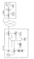
本発明による監視システムの一実施例について図1を用いて説明する。図1は本発明の一実施例の監視システム構成を示すブロック図である。
図1において、1は図示していない被写体を撮像する雲台カメラ装置であり、3は雲台カメラ装置1から伝送されてくる映像信号や自己診断情報等の表示および雲台カメラ装置1を制御する制御端末装置であり、2は雲台カメラ装置1から出力する映像信号等を制御端末装置3に伝送するためのインターネット等のネットワークである。雲台カメラ装置1において、101は図示しない被写体からの光を結像するレンズ部、102はレンズ部101で結像した光を光電変換する撮像部、103は撮像部102から出力される映像信号と自己診断情報をネットワーク2に配信するための送受信部、104は雲台カメラ装置1の制御と自己診断を行うCPU(Central Processing Unit)、105はレンズ部101を制御するためのレンズ制御部、106はレンズ部101を含む撮像部102を旋回させるための旋回駆動部、107はレンズ部101を含む撮像部102を仰角方向に動かす仰角駆動部、108は旋回駆動部106と仰角駆動部107を制御する雲台制御部、109は雲台カメラ装置1の各部に電源を供給する電源部、110は雲台カメラ装置1の内部温度を測定する温度センサ部、111は自己診断情報を記憶するメモリ部である。制御端末装置において、301は雲台カメラ装置1と映像信号や制御信号等を送受信するための送受信部、302は雲台カメラ装置1と制御端末装置3の各部を制御する制御部、303は雲台カメラ装置1から伝送されてくる映像信号や自己診断情報を表示する表示部、304は制御部302を操作する操作部、305は雲台カメラ装置1から伝送されてくる映像信号や自己診断情報を記憶するメモリ部である。
An embodiment of the monitoring system according to the present invention will be described with reference to FIG. FIG. 1 is a block diagram showing the configuration of a monitoring system according to an embodiment of the present invention.
In FIG. 1, reference numeral 1 denotes a pan head camera device that captures an object (not shown), and reference numeral 3 denotes display of video signals and self-diagnosis information transmitted from the pan head camera device 1 and control of the pan head camera device 1. 2 is a network such as the Internet for transmitting a video signal or the like output from the camera platform camera device 1 to the control terminal device 3. In the
雲台カメラ装置1は、フォーカスおよびズーム倍率が変更可能なレンズ部101と、水平方向の旋回角が変更可能な旋回駆動部106と、垂直方向の仰角が変更可能な仰角駆動部107で、撮像方向および視野を変えることができる。
The pan / tilt head camera apparatus 1 includes a
次に図1の動作について説明する。雲台カメラ装置1のレンズ部101は図示していない被写体からの光を撮像部102に結像し、撮像部102は結像された光を映像信号に光電変換して送受信部103に出力する。送受信部103は入力された映像信号にCPU104から出力された情報データを重畳してネットワーク2に配信する。制御端末装置3の送受信部301は雲台カメラ装置1から配信された映像信号と情報データを受信して制御部302に出力する。制御部302は入力された映像信号と情報データをメモリ部305に記憶させると共に表示部303に表示する。制御端末装置3から雲台カメラ装置1の遠隔操作は、操作者が制御端末装置3の操作部304を操作して行う。操作者が操作部304を操作した指示信号は、制御部302で雲台カメラ装置1の制御信号として送受信部301を介してネットワーク2に配信する。雲台カメラ装置1の送受信部103は制御端末装置3から配信された制御信号を受信してCPU104に出力する。CPU104は入力された制御信号に従って、レンズ制御部105を介してレンズ部101のフォーカスおよびズームの制御、雲台制御部108を介して旋回駆動部106および仰角制御部107の制御を行う。また、CPU104は雲台カメラ装置1の各部の制御と、レンズ部101のフォーカスおよびズームの可動回数と、旋回駆動部106の可動回数と、仰角制御部107の可動回数を計数してメモリ部111に記憶する。
Next, the operation of FIG. 1 will be described. The
次に本発明の自己診断の一実施例を図1乃至図4を用いて説明する。図2は本発明の一実施例の自己診断設定画面を示す図である。
始めに操作者は表示部303に表示した図2の自己診断設定画面を見ながら操作部304を操作して雲台カメラ装置1の自己診断の設定を遠隔操作で行う。本発明の一実施例の設定として、データの取得間隔を1分、メモリ部111への記録間隔を1分、制御端末装置3へのデータ送信間隔を12時間、レンズ部101のフォーカス可動回数の最大値を5万回、レンズ部101のズーム可動回数の最大値を5万回、旋回駆動部106の可動回数の最大値を5万回、仰角駆動部107の可動回数の最大値を5万回、内部温度許容値の最低温度を0℃、内部温度許容値の最高温度を+40℃に設定する。操作者は図2に示す自己診断設定情報データをメモリ部305に記憶すると共に雲台カメラ装置1のCPU104に伝送する。CPU104に伝送された自己診断設定情報データはCPU104経由でメモリ部111に記憶する。CPU104は自己診断設定情報に従って自己診断を開始する。図2に示す設定は雲台カメラ装置1側で行っても良い。
Next, one embodiment of the self-diagnosis of the present invention will be described with reference to FIGS. FIG. 2 is a diagram showing a self-diagnosis setting screen according to an embodiment of the present invention.
First, the operator operates the
次に本発明の一実施例の自己診断の動作について図3と図4を用いて説明する。図3は本発明の一実施例の自己診断項目と取得データを示す図であり、図4は本発明の一実施例の動作を説明するためのフローチャートである。 Next, the self-diagnosis operation of one embodiment of the present invention will be described with reference to FIGS. FIG. 3 is a diagram showing self-diagnosis items and acquired data according to an embodiment of the present invention, and FIG. 4 is a flowchart for explaining the operation of the embodiment of the present invention.
CPU104は図4の“開始”から自己診断を開始する。ステップS1の初期設定でメモリ部111に記憶してある自己診断設定情報データを読み出す。ステップS2で設定したデータ取得間隔の1分毎に図3に示す雲台カメラ装置1の稼動時間、レンズ部101のフォーカス可動回数とズーム可動回数、旋回駆動部106の可動回数、仰角駆動部107の可動回数、温度センサ部110で測定した温度、映像信号状態、電源部109の状態、送受信部103の通信状態のデータを取得する。ステップS3で取得した取得データが正常かを判別する。判別方法は図2の自己診断設定画面で設定した設定値と所得データを比較して最大値以下又は許容値範囲内であれば正常と判別してステップS4の処理に進み、比較結果が最大値超又は許容値範囲外であればステップS7の処理に進む。
The
ステップS4で取得データと前回までに取得したデータの変動量の平均値とを比較し、例えば5倍以下の変動量があれば許容内と判断してステップS5の処理に進み、例えば5倍超の変動量であれば許容外としてステップS7に進む。ステップS4の許容値は予め設定しておき、また稼動時間により許容値を数段階に変更できる設定であっても良い。ステップS4の処理の変動量の平均値を図3のフォーカスの可動累積回数で説明すると、2005/09/30 00:00の取得データは0回、2005/09/30 12:00の取得データは12回、2005/10/01 00:00の取得データは24回であるため、変動量の平均値は12回となる。ステップS4の処理の変動量の許容値を例えば5とすると、2005/10/01 12:00の取得データが24(005/10/01 00:00の取得データ)+12(変動量の平均値)×5(許容値)=84の式から84回以下なら許容内となる。このステップS4は例えばフォーカス可動回数が最大値以下でも通常より極端に可動回数が増加した場合は故障等の異常の兆候であるため、この処理で故障等の異常の兆候を検出できる。 In step S4, the acquired data is compared with the average value of the fluctuation amount of the data acquired up to the previous time. If the amount of change is not acceptable, the process proceeds to step S7. The allowable value in step S4 may be set in advance, or may be set such that the allowable value can be changed in several stages depending on the operation time. The average value of the fluctuation amount of the processing in step S4 will be described by the movable cumulative number of focus in FIG. 3. The acquired data at 00:00 on September 30, 2005 is 0, and the acquired data at 12:00 on 2005/09/30 is Since the acquired data of 12 times, 2005/10/01 00:00 is 24 times, the average value of the fluctuation amount is 12 times. Assuming that the allowable value of the fluctuation amount of the process in step S4 is 5, for example, the acquired data of 2005/10/01 12:00 is 24 (acquired data of 005/10/01 00:00) +12 (average value of the fluctuation amount). From the formula x5 (allowable value) = 84, if it is 84 times or less, it is within the allowable range. In this step S4, for example, when the number of movements is extremely greater than usual even when the number of focus movements is equal to or less than the maximum value, it is a sign of abnormality such as a failure.
ステップS5でメモリ部111への設定の記録間隔の1分で取得データをメモリ部111に記録する。ステップS6で制御端末装置3に設定の送信間隔の12時間で最新情報データ又は未送信の情報データをメモリ部111から読み出して雲台カメラ装置番号の“0001”と共に送受信部103から送信する。ステップS7ではメモリ部111への設定の記録間隔とは無関係に取得データをメモリ部111に記録する。ステップS8では制御端末装置3に設定の送信間隔とは無関係に最新データ又は未送信の情報データをメモリ部111から読み出して雲台カメラ装置番号の“0001”と共に送受信部103から送信する。
In step S5, the acquired data is recorded in the
次に、図1と図3を用いて制御端末装置3の動作の一実施例について説明する。雲台カメラ装置1から送信された映像信号及び自己診断情報データは、ネットワーク2を介して制御端末装置3の送受信部301に伝送される。伝送された映像信号及び自己診断情報データは制御部302を介してメモリ部305に記録及び表示部303に表示される。表示部303に表示された自己診断情報データを図3に示す。図3は伝送されてきた雲台カメラ装置1の雲台カメラ装置番号“0001”と、図2の自己診断設定画面で設定したデータの送信間隔である12時間毎に送信された自己診断情報データを表示したものである。図3のデータ取得時間2005/10/10 08:28は映像信号の項目で異常となったため、設定した情報データの送信間隔以外の時間で自己診断情報データが伝送されたことを示している。また、図3のデータ取得時間2005/10/10 12:12は映像信号の項目が正常となったため、設定した情報データの送信間隔以外の時間で自己診断情報データが伝送されたことを示している。図3のデータ取得時間2005/10/10 08:28は映像信号の項目で“異常”の表示色は、他のデータ又は情報の表示色と変えても良いし、また、“異常”の表示は点滅させても良い。
Next, an example of the operation of the control terminal device 3 will be described with reference to FIGS. 1 and 3. The video signal and self-diagnosis information data transmitted from the camera platform camera device 1 are transmitted to the transmission /
上記の一実施例では雲台カメラ装置1と制御端末装置3を各1台で説明したが、雲台カメラ装置1と制御端末装置3を各々複数台あっても良い。
本発明は、監視システム、特にカメラ装置1の状態や機構の稼動状態を定期的に制御端末装置3で把握することができるため、カメラ装置1に故障が起きる前に保守点検を行うことができる。更に、カメラ装置1に故障が起きた場合は故障状態を制御端末装置3の表示部303に表示することができるため、カメラ装置1の故障時間を低減することができる。
In the above embodiment, the pan head camera apparatus 1 and the control terminal apparatus 3 are described as one unit, but a plurality of pan head camera apparatuses 1 and control terminal apparatuses 3 may be provided.
According to the present invention, since the control terminal device 3 can periodically grasp the state of the monitoring system, particularly the camera device 1 and the operating state of the mechanism, the maintenance check can be performed before the camera device 1 breaks down. . Furthermore, when a failure occurs in the camera device 1, the failure state can be displayed on the display unit 303 of the control terminal device 3, so that the failure time of the camera device 1 can be reduced.
以上本発明について詳細に説明したが、本発明は、ここに記載された監視システムに限定されるものではなく、上記以外の監視システムに広く適用することができることは言うまでもない。 Although the present invention has been described in detail above, it is needless to say that the present invention is not limited to the monitoring system described herein, and can be widely applied to other monitoring systems.
1:雲台カメラ装置、2:ネットワーク、3:制御端末装置、101:レンズ部、102:撮像部、103:送受信部、104:CPU、105:レンズ制御部、106:旋回駆動部、107:仰角駆動部、108:雲台制御部、109:電源部、110:温度センサ部、111:メモリ部、301:送受信部、302:制御部、303:表示部、304:操作部、305:メモリ部。 1: pan head camera device, 2: network, 3: control terminal device, 101: lens unit, 102: imaging unit, 103: transmission / reception unit, 104: CPU, 105: lens control unit, 106: turning drive unit, 107: Elevation angle drive unit, 108: pan head control unit, 109: power supply unit, 110: temperature sensor unit, 111: memory unit, 301: transmission / reception unit, 302: control unit, 303: display unit, 304: operation unit, 305: memory Department.
Claims (2)
レンズ部で結像した光を光電変換して映像信号を出力する撮像部と、An imaging unit that photoelectrically converts light imaged by the lens unit and outputs a video signal;
前記レンズ部と前記撮像部を水平方向に旋回させる水平旋回駆動部と、A horizontal turning drive unit for turning the lens unit and the imaging unit in a horizontal direction;
前記レンズ部と前記撮像部を垂直方向に旋回させる垂直旋回駆動部と、A vertical turning drive unit for turning the lens unit and the imaging unit in a vertical direction;
前記レンズ部、前記撮像部、前記水平旋回駆動部および前記垂直旋回駆動部を制御し、少なくとも、前記レンズ部からのフォーカスまたはズーム倍率の調整回数と、前記水平旋回駆動部および前記垂直旋回駆動部からのそれぞれ旋回回数とからなる状態データを取得する制御部と、The lens unit, the imaging unit, the horizontal turning drive unit and the vertical turning drive unit are controlled, and at least the number of adjustments of focus or zoom magnification from the lens unit, the horizontal turning drive unit and the vertical turning drive unit are controlled. A control unit for acquiring state data consisting of the number of turns from
事前に設定した前記制御部によるデータ取得間隔、前記メモリ部へのデータ記録間隔、外部への自己診断データ送信間隔、前記レンズ部のフォーカスまたはズームの許容調整回数、前記水平旋回駆動部の許容旋回回数、および、前記垂直旋回駆動部の許容旋回回数からなる設定データ、並びに、前記状態データを記録するメモリ部と、Data acquisition interval by the control unit set in advance, data recording interval to the memory unit, self-diagnosis data transmission interval to the outside, the number of allowable adjustments of focus or zoom of the lens unit, allowable swing of the horizontal turning drive unit A memory unit for recording the number of times and setting data including the allowable number of turns of the vertical turning drive unit, and the state data;
外部と信号をやりとりする送受信部と、を備え、A transmission / reception unit for exchanging signals with the outside,
前記制御部は、前記状態データと前記設定データとを比較して自己診断データを生成し、前記自己診断データが正常を示す場合は前記設定データに従った送信間隔で前記自己診断データを前記送受信部から外部へ送信し、前記自己診断データが異常を示す場合は前記設定データとは異なる送信間隔で前記自己診断データを前記送受信部から外部へ送信することを特徴とする雲台カメラ装置。The control unit compares the status data with the setting data to generate self-diagnosis data. When the self-diagnosis data indicates normality, the control unit transmits and receives the self-diagnosis data at a transmission interval according to the setting data. A camera platform camera device, wherein the self-diagnosis data is transmitted from the transmission / reception unit to the outside at a transmission interval different from the setting data when the self-diagnosis data indicates an abnormality.
前記操作部からの入力信号に応じて制御信号を出力する制御部と、A control unit that outputs a control signal in response to an input signal from the operation unit;
映像や各種情報を表示する表示部と、A display for displaying video and various information,
外部と信号をやりとりする送受信部と、を備える制御端末装置と、A control terminal device comprising a transmission / reception unit for exchanging signals with the outside;
請求項1に記載の雲台カメラ装置と、から構成され、A pan head camera device according to claim 1,
前記雲台カメラ装置と前記制御端末装置とはネットワークにより接続され、The pan head camera device and the control terminal device are connected by a network,
前記制御端末装置の操作部および制御部により、前記雲台カメラ装置の前記設定データのパラメータが設定され、Parameters of the setting data of the pan head camera device are set by the operation unit and the control unit of the control terminal device,
前記制御端末は、前記雲台カメラ装置から送信された前記自己診断データを受信すると、前記自己診断データに応じて表示部に前記雲台カメラの自己診断結果を表示することを特徴とする監視システム。When the control terminal receives the self-diagnosis data transmitted from the pan head camera device, the control terminal displays a self-diagnosis result of the pan head camera on a display unit according to the self-diagnosis data. .
Priority Applications (1)
| Application Number | Priority Date | Filing Date | Title |
|---|---|---|---|
| JP2005309706A JP4641925B2 (en) | 2005-10-25 | 2005-10-25 | Pan head camera device and monitoring system |
Applications Claiming Priority (1)
| Application Number | Priority Date | Filing Date | Title |
|---|---|---|---|
| JP2005309706A JP4641925B2 (en) | 2005-10-25 | 2005-10-25 | Pan head camera device and monitoring system |
Publications (2)
| Publication Number | Publication Date |
|---|---|
| JP2007124009A JP2007124009A (en) | 2007-05-17 |
| JP4641925B2 true JP4641925B2 (en) | 2011-03-02 |
Family
ID=38147402
Family Applications (1)
| Application Number | Title | Priority Date | Filing Date |
|---|---|---|---|
| JP2005309706A Expired - Fee Related JP4641925B2 (en) | 2005-10-25 | 2005-10-25 | Pan head camera device and monitoring system |
Country Status (1)
| Country | Link |
|---|---|
| JP (1) | JP4641925B2 (en) |
Families Citing this family (2)
| Publication number | Priority date | Publication date | Assignee | Title |
|---|---|---|---|---|
| JP2017212596A (en) * | 2016-05-25 | 2017-11-30 | 株式会社東芝 | Camera maintenance support device, camera maintenance support method and remote monitoring system |
| KR102617992B1 (en) | 2016-12-27 | 2023-12-26 | 한화비전 주식회사 | Predictive diagnosis apparatus and surveillance system |
Family Cites Families (4)
| Publication number | Priority date | Publication date | Assignee | Title |
|---|---|---|---|---|
| JP3410760B2 (en) * | 1993-04-16 | 2003-05-26 | 富士写真光機株式会社 | Television camera lens condition monitoring device |
| JPH10171014A (en) * | 1996-12-06 | 1998-06-26 | Fuji Photo Optical Co Ltd | Remote-controlled universal head system |
| JP3246409B2 (en) * | 1997-09-30 | 2002-01-15 | 日本電気株式会社 | Fault monitoring method |
| JP4061737B2 (en) * | 1998-10-05 | 2008-03-19 | フジノン株式会社 | Pan head device |
-
2005
- 2005-10-25 JP JP2005309706A patent/JP4641925B2/en not_active Expired - Fee Related
Also Published As
| Publication number | Publication date |
|---|---|
| JP2007124009A (en) | 2007-05-17 |
Similar Documents
| Publication | Publication Date | Title |
|---|---|---|
| US20110090341A1 (en) | Intruding object detection system and controlling method thereof | |
| US10306211B2 (en) | Remote control of pivotable stereoscopic camera | |
| JPH10294933A (en) | Video surveillance system | |
| WO2009102098A1 (en) | Intellection type monitoring system and intellection type monitoring method using a cctv system | |
| US20110037862A1 (en) | Adjustment system and method for camera | |
| JP4641925B2 (en) | Pan head camera device and monitoring system | |
| US20190124250A1 (en) | Endoscope device for an automatic examination | |
| JP4566908B2 (en) | Imaging system | |
| JP2012119971A (en) | Monitoring video display unit | |
| JP2010074527A (en) | Monitor control apparatus, and monitor system | |
| EP4425946A1 (en) | Security camera with self-calibration of pan and/or tilt operations | |
| US20250016290A1 (en) | Feedback control panoramic monitoring and feedback control system and method | |
| US11922610B2 (en) | Multi-eye camera system, multi-eye photographing camera head, image processing device, multi-eye photographing program and multi-eye photographing method | |
| KR20210039037A (en) | Condition Monotoring System Using CCTV | |
| JP2012019285A (en) | Imaging device and imaging method | |
| KR102247071B1 (en) | Cctv camera system with having self-detection | |
| JP2018174555A (en) | Device, system, and program | |
| EP3116224A1 (en) | Method and device for exchanging protocol | |
| JP4371795B2 (en) | Imaging apparatus and imaging system | |
| JPH05130646A (en) | Stereoscopic camera device | |
| JP2008312026A (en) | Surveillance camera device | |
| CN218868290U (en) | Camera monitoring system | |
| JP2019193283A (en) | System and program | |
| KR20110140011A (en) | Camera module and monitoring device equipped with the same | |
| KR19990053940A (en) | How to check the operating status of the video camera |
Legal Events
| Date | Code | Title | Description |
|---|---|---|---|
| A621 | Written request for application examination |
Free format text: JAPANESE INTERMEDIATE CODE: A621 Effective date: 20080714 |
|
| A131 | Notification of reasons for refusal |
Free format text: JAPANESE INTERMEDIATE CODE: A131 Effective date: 20100907 |
|
| A521 | Request for written amendment filed |
Free format text: JAPANESE INTERMEDIATE CODE: A523 Effective date: 20101104 |
|
| TRDD | Decision of grant or rejection written | ||
| A01 | Written decision to grant a patent or to grant a registration (utility model) |
Free format text: JAPANESE INTERMEDIATE CODE: A01 Effective date: 20101124 |
|
| A01 | Written decision to grant a patent or to grant a registration (utility model) |
Free format text: JAPANESE INTERMEDIATE CODE: A01 |
|
| A61 | First payment of annual fees (during grant procedure) |
Free format text: JAPANESE INTERMEDIATE CODE: A61 Effective date: 20101130 |
|
| R150 | Certificate of patent or registration of utility model |
Ref document number: 4641925 Country of ref document: JP Free format text: JAPANESE INTERMEDIATE CODE: R150 Free format text: JAPANESE INTERMEDIATE CODE: R150 |
|
| FPAY | Renewal fee payment (event date is renewal date of database) |
Free format text: PAYMENT UNTIL: 20131210 Year of fee payment: 3 |
|
| R250 | Receipt of annual fees |
Free format text: JAPANESE INTERMEDIATE CODE: R250 |
|
| R250 | Receipt of annual fees |
Free format text: JAPANESE INTERMEDIATE CODE: R250 |
|
| R250 | Receipt of annual fees |
Free format text: JAPANESE INTERMEDIATE CODE: R250 |
|
| R250 | Receipt of annual fees |
Free format text: JAPANESE INTERMEDIATE CODE: R250 |
|
| LAPS | Cancellation because of no payment of annual fees |