JP4641474B2 - Image forming apparatus - Google Patents
Image forming apparatus Download PDFInfo
- Publication number
- JP4641474B2 JP4641474B2 JP2005265523A JP2005265523A JP4641474B2 JP 4641474 B2 JP4641474 B2 JP 4641474B2 JP 2005265523 A JP2005265523 A JP 2005265523A JP 2005265523 A JP2005265523 A JP 2005265523A JP 4641474 B2 JP4641474 B2 JP 4641474B2
- Authority
- JP
- Japan
- Prior art keywords
- image
- sheet
- images
- sheets
- cutting
- Prior art date
- Legal status (The legal status is an assumption and is not a legal conclusion. Google has not performed a legal analysis and makes no representation as to the accuracy of the status listed.)
- Expired - Fee Related
Links
Images


Landscapes
- Record Information Processing For Printing (AREA)
- Control Or Security For Electrophotography (AREA)
- Editing Of Facsimile Originals (AREA)
Description
本発明は、シートに画像を形成する画像形成装置に関する。 The present invention relates to an image forming apparatus that forms an image on a sheet.
近年の高度情報化社会の進展に伴い、映像のカラー化が急速に進んでいる。 With the progress of the advanced information society in recent years, the colorization of images is progressing rapidly.
電子写真方式の複写機やプリンタの分野におけるカラー化の進展も目覚しいものがある。 There is also a remarkable progress in colorization in the field of electrophotographic copying machines and printers.
また、映像をモニターしながら撮影したり、撮影した映像を再生して確認したり、ネットワークを用いて撮影した映像を伝送することができるという利便性から、デジタルスチルカメラの普及は目覚しいものがあり、デジタルスチルカメラで撮影した映像をカラープリンタなどでハードコピーしたい、というニーズが高まっている。 In addition, the popularity of digital still cameras is remarkable due to the convenience of being able to shoot while monitoring the video, play back and check the video, and transmit the video taken over the network. There is a growing need for hard-copying video shot with a digital still camera with a color printer.
しかしながら、電子写真方式のプリンタにおける画質は、銀塩方式やインクジェット方式に比べ、写真画質という点で一般的に光沢性が不足している。 However, the image quality of electrophotographic printers is generally lacking in gloss in terms of photographic image quality compared to silver salt and ink jet systems.
そのため従来より、高光沢写真画質の画像を出力するための種々の装置が提案されている。 For this reason, various apparatuses have been proposed for outputting high-gloss photographic image quality.
光沢性に優れたカラー画像が得られるカラー画像形成方法として、熱可塑性樹脂からなる透明樹脂層を形成した転写体(記録シートなど)にカラートナーを溶融、固着してカラー画像を形成するに際し、熱源を内蔵する部材したに移動するベルト状搬送体により、転写体の透明樹脂層上に付着したカラートナーを加熱して透明樹脂層中に溶融させ、次いで冷却して固着させ、さらに転写体をベルト状搬送体から分離してカラー画像を形成することが知られている(特許文献1参照)。 As a color image forming method for obtaining a color image with excellent glossiness, when a color toner is melted and fixed on a transfer body (such as a recording sheet) on which a transparent resin layer made of a thermoplastic resin is formed, a color image is formed. The color toner adhered on the transparent resin layer of the transfer body is heated and melted in the transparent resin layer by the belt-like conveyance body that moves to the member containing the heat source, and then cooled and fixed, and the transfer body is further fixed. It is known that a color image is formed separately from a belt-shaped carrier (see Patent Document 1).
この画像形成方法によれば、カラートナー像が透明樹脂層中に埋め込まれるように定着されるため、そのカラー画像において照明光の乱反射が防止され、カラー画像からの反射または透過の光量が豊富になり優れた光沢性を付与できるとされている。 According to this image forming method, since the color toner image is fixed so as to be embedded in the transparent resin layer, irregular reflection of illumination light is prevented in the color image, and the amount of reflected or transmitted light from the color image is abundant. It is said that excellent gloss can be imparted.
ところで、カラー画像形成装置を印刷市場や写真市場に展開する際に、グラフィックアートプリントや写真サービスではごく常識的な、用紙端部に余白の無い画像(以下、縁無しプリントと呼ぶ)が強く要求されている。 By the way, when developing color image forming devices in the printing market and the photographic market, there is a strong demand for images with no margins on the edge of the paper (hereinafter referred to as borderless printing), which is very common in graphic art prints and photo services. Has been.
この要求に答えるために、定着後に裁断手段を備え、用紙端部に余白有りで画像を形成した後に四辺をカットする装置が提案されている(特許文献2参照)。 In order to meet this requirement, there has been proposed an apparatus that includes a cutting means after fixing and cuts four sides after forming an image with a margin at the end of the paper (see Patent Document 2).
また、特開平9−123562には、ページごとの画像データの複数ページ分を1枚の用紙の片面に印刷する場合に、印刷後に用紙を裁断することが記載されている。さらに、その裁断された部分を重ねて冊子としたとき、用紙の切断面が冊子の一定の辺に揃うようにしたことが記載されている。
しかしながら特許文献1に示される装置において、写真画質を与えるための手段は、A6版やL版(89mm×127mm)といった小さいプリントサイズに限定して提案されている。
However, in the apparatus disclosed in
これは、写真画質のプリントサイズに対するニーズの大半がL版であることに起因する。一方、プリンタ装置の多くはA4サイズ幅(=297mm)の用紙まで対応していることが多い。上述の提案ではベルト定着の幅方向寸法をA6版程度に設定しているため、光沢付与装置の幅自体を小さくできるというメリットはあるものの、プリンタ装置がもつ性能を最大限に発揮していない感があった。 This is due to the fact that most of the needs for the photographic quality print size are the L version. On the other hand, many printers are compatible with A4 size paper (= 297 mm). In the above proposal, the belt fixing width direction dimension is set to about A6 size, so there is a merit that the width of the gloss imparting device itself can be reduced, but the feeling that the printer device does not exhibit the maximum performance. was there.
また特許文献2に示される装置においても、特許文献1の装置に対応するべく、用紙の四辺をカットするものであり、同様にプリンタ装置が持つ性能を最大限に生かすための装置ではなかった。
The apparatus disclosed in
この問題を解決するために、一般的によく使われるL版(89×127)サイズをA4(210×297)の用紙に割り付け、最大4枚を一度に出力することが考えられる。 In order to solve this problem, it is conceivable to assign a commonly used L size (89 × 127) size to A4 (210 × 297) paper and output a maximum of 4 sheets at a time.
この装置によると、従来の4倍近くの生産性が得られる。 According to this apparatus, the productivity nearly four times that of the conventional one can be obtained.
さらに、裁断手段も従来の四辺裁断から、最大八辺の裁断をおこなうことにより、A4用紙からL判を4枚切り出すことができる。 Further, the cutting means can cut out four L sizes from A4 paper by cutting up to eight sides from the conventional four-sided cutting.
ところがこの種の装置では、裁断手段から裁断された出力紙がばらばらになるという不具合があった。 However, this type of apparatus has a problem that the output paper cut by the cutting means is separated.
また、特許文献3に示される装置においては、出力された用紙を積載した後に裁断する構成であったために裁断見栄えのよい裁断をすることが難しい。
In addition, the apparatus disclosed in
上記目的を達成するため、本発明の画像形成装置は、一枚のシートに複数の画像を形成可能であって、画像順が連続した複数の画像を複数のシート上に割り当てて形成する画像形成部と、前記画像形成部によって画像が形成されたシートを搬送する搬送部と、前記搬送部によるシート搬送方向に沿う方向と前記シート搬送方向と垂直な方向とに、前記搬送部によって搬送されるシート毎に裁断する裁断装置と、前記裁断装置によって裁断された裁断後シートが複数列で積載される排出トレイと、前記画像順が連続した複数の画像を、前記裁断装置により裁断される前の複数のシート上に割り当てる際、前記排出トレイに複数列で積載された裁断後シートの束の画像順が前記複数の列において連続するように割り当てて画像形成するように前記画像形成部を制御する制御部と、を有し、前記裁断装置によって裁断された裁断後シートに複数の白紙が発生する場合、前記排紙トレイ上の複数列のうちの一つの列に複数の白紙が配置され、且つ、前記排紙トレイ上に積載された複数列の出力紙を、ページ順が連続するように上下方向に積み重ねたとき、連続したページの先頭側または最後尾側に前記複数の白紙が集結するように、前記画像形成部を前記制御部が制御する。 In order to achieve the above object, the image forming apparatus of the present invention is capable of forming a plurality of images on a single sheet, and forming an image by allocating a plurality of images in a sequence of images to a plurality of sheets. A conveyance unit that conveys a sheet on which an image is formed by the image forming unit, a direction along a sheet conveyance direction by the conveyance unit, and a direction perpendicular to the sheet conveyance direction. A cutting device that cuts each sheet, a discharge tray on which sheets after cutting cut by the cutting device are stacked in a plurality of rows, and a plurality of images in which the image order is continuous before the cutting device cuts the plurality of images. When allocating on a plurality of sheets, the image order of the bundle of sheets after cutting stacked in a plurality of rows on the discharge tray is assigned so as to be continuous in the plurality of rows to form an image. Possess a control unit that controls the image forming unit, when the cutting plurality of white paper shredded cut sheet after the device generates a plurality of to one row of a plurality of rows on the discharge tray When a plurality of rows of output sheets stacked on the paper discharge tray are stacked in the vertical direction so that the page order is continuous, the plurality of sheets are arranged on the leading side or the trailing side of the continuous pages. The control unit controls the image forming unit so that the blank sheets of paper are gathered .
以上説明したように、本発明によれば、一枚のシートに複数の画像を形成することで生産性を向上させながら、出力されたシートの順番を揃えなおしたりする必要がなくなる。 As described above, according to the present invention, it is not necessary to rearrange the order of the output sheets while improving productivity by forming a plurality of images on one sheet.
(第1実施形態)
本発明の実施形態について図1〜9及び図18乃至図20を用いて説明する。
(First embodiment)
An embodiment of the present invention will be described with reference to FIGS. 1 to 9 and FIGS. 18 to 20.
図1には本発明実施形態であるイエロー、シアン、マゼンタ、ブラックの4色のトナーによるフルカラー画像形成装置の概略断面図を示す。 FIG. 1 is a schematic sectional view of a full-color image forming apparatus using four color toners of yellow, cyan, magenta, and black according to an embodiment of the present invention.
本実施例による装置は、プリンタ部1の上部にリーダ部2を備え、かつプリンタ部1の側部にベルト定着装置3、裁断装置4を備えた光沢処理装置5が配設されている。
The apparatus according to this embodiment includes a
リーダ部2は、原稿の画像を読み取るためのものである。
The
プリンタ部1は、側方にシートが積載される手差し給紙部15を有する。プリンタ部1は、給紙カセット14a、14b、14cを下方に有する。
The
プリンタ部1は、感光体ドラム8、レーザーレーザースキャナユニット7、回動型現像体10、中間転写ベルト12、2次転写部13等を有する。
The
更にプリンタ部1には定着装置6が設けられている。プリンタ部1の側方には画像が形成されたシートが排出される排出トレイ19と排出トレイ19にシートを排出する排出ローラ18が設けられている。
Further, the
プリンタ部1には画像が形成されたシートを上方に搬送する縦パス17、と縦パス17を搬送されたシートを反転する反転パス20とを有する、反転パス20には正逆転可能な反転ローラ対22が設けられている。プリンタ部1は、縦パス17及び反転パス20を通過したシートシートを光沢処理装置5へ搬送することができる。この画像形成装置においては、操作表示ユニットである操作パネルPから所定の選択指示を行うことにより、一般の画像出力(コピー、プリント)を行う出力モード(通常プリントモード)と、光沢性を付与する画像出力を行う出力モード(写真プリントモード)とのいずれかを選択できるようになっている。
The
また、この画像形成装置においては、上記各出力モードに応じた特有の画像形成プロセスパターンが選択設定されるようになっている。 In this image forming apparatus, a specific image forming process pattern corresponding to each output mode is selected and set.
すなわち、画像形成をおこなうに際して、前記通常プリントモードを選択した場合には、定着ユニット6による定着を行った後に(光沢処理装置5には送られず)排出トレイ19に排出されるプロセスパターンが選択される。
That is, when the normal print mode is selected at the time of image formation, a process pattern to be discharged to the
一方、写真プリントモードを選択した場合には、定着ユニット6による定着を行った後に光沢処理装置5による光沢処理を行うプロセスパターンが選択される。
On the other hand, when the photo print mode is selected, a process pattern for performing gloss processing by the gloss processing device 5 after fixing by the
ここで、写真プリントモードによる画像形成を行う場合には、通常はシート基材(普通紙など)の少なくとも片面にポリエステル樹脂からなる透明な受像層82を5〜20μm程度の厚さに形成した写真プリント用記録紙が使用される。 Here, in the case of performing image formation in the photographic print mode, usually, a photograph in which a transparent image receiving layer 82 made of a polyester resin is formed to a thickness of about 5 to 20 μm on at least one side of a sheet substrate (plain paper or the like). Printing paper is used.
このような写真プリント用記録紙は、その受像層82が形成された面が全面にわたって均一な光沢感を有している。 Such a recording sheet for photographic print has a uniform gloss feeling over the entire surface on which the image receiving layer 82 is formed.
プリンタ部1による画像形成動作について説明する。なおプリンタ部1による画像形成の動作は、制御部Cがプリンタ部1を制御することによって行なわれる。
An image forming operation by the
パソコンなどの外部機器から出力された画像、もしくはリーダ部2において読み取った画像は、レーザースキャナユニット7にて各色毎(各色ステーション毎)の光信号に変換される。光信号に変換されたレーザー光がポリゴンミラーで反射され、レンズ及び折り返しミラーを経てそれぞれの感光ドラム8のドラム表面に露光される。
An image output from an external device such as a personal computer or an image read by the
感光ドラム8の周りには、帯電器9、現像ロータリー10内に構成された各々の現像器(10a,10b,10c,10d)、感光ドラムクリーニング装置11が配置されている。感光ドラム8上の露光を現像ロータリーの回転により、現像器をその都度切り替える行程を必要色の分繰り返す。この工程によって各色現像し、その都度中間転写ベルト12の上にトナー像を1次転写し、必要色、中間転写ベルト12上に画像を重ね合わせたる。そして、シート中間転写ベルト12上のトナー像を2次転写部13によってシートに転写される。
Around the
なお、中間転写ベルト上の画像に合わせるように、シートはカセット14a,14b,14c,或いはマルチ手差し15より繰り出し、搬送される。シートは、レジストローラ16で斜行補正及びタイミング取りを行った後、2次転写部13に向けて搬送される。
The sheet is fed out from the
その後、2次転写部13にて、中間転写体である中間転写ベルト12上のトナー像をシート上に2次転写し、シート上に重ね合わされた画像が転写される。
Thereafter, the
2次転写部13を抜けたシートは、定着装置6にてトナーを熱定着し、その後、内排紙ローラ16を通過する。内排紙ローラ16を通過したシートは第1分岐部17aへと進む。
The sheet that has passed through the
その後、第1分岐部17aに到達したシートは、以下のいずれかの工程パターンを経ることになる。 Thereafter, the sheet that has reached the first branch portion 17a goes through one of the following process patterns.
1つは、前述の通常プリントモードを選択した場合であり、この場合にシートは、第1分岐部17aから排出ローラ18へと向かい、排出トレイ19へ排出される。
One is a case where the above-described normal print mode is selected. In this case, the sheet is discharged from the first branch portion 17 a to the
写真プリントモードを選択した場合には、シートは第1分岐部17aを経た後、縦パス17を経て反転パス20の方向へと向かう経路を通過する。そして、縦パス17から分岐部21を直進し、反転ローラ22方向へと進み、シートの後端が分岐部21を通過し終えたところで、反転ローラ22を逆転させる。反転ローラ22逆転前のシートの後端を、逆転後にはシート搬送方向の先端側とした状態で光沢処理装置5へと進入させる。
When the photo print mode is selected, the sheet passes through the first branching portion 17a, and then passes through the path toward the
第1分岐部17a、および第2分岐部21には図示しない搬送方向切換ゲートが設けられており、所定のタイミングで切り替わることにより、上記搬送方向の切り替えをおこなっている。 The first branch portion 17a and the second branch portion 21 are provided with a transport direction switching gate (not shown), and the transport direction is switched by switching at a predetermined timing.
なお、ここで、写真プリントモードによる画像形成を行う場合に用紙を反転させている理由であるが、後述にも記載するように、ベルト定着装置3のベルト面に画像面を対向させるためである。
Here, the reason for reversing the sheet when performing image formation in the photo print mode is to make the image surface face the belt surface of the
次に、光沢処理装置5の構成を説明する。 Next, the configuration of the gloss processing device 5 will be described.
光沢処理装置5にはベルト定着装置8と裁断装置4とが設けられている。
The gloss processing device 5 is provided with a
ベルト定着装置3は、光沢を付与するための装置であり、定着ユニット6の用紙搬送方向の下流側に配置されている。
The
図2に詳細を示したベルト定着装置3は、加熱ロール31と、剥離ロール32と、ステアリングロール33と、各ロール31〜33に架け回された定着ベルト34と、を有する。ベルト定着装置3はさらに、定着ベルト34を加熱ロール31に押圧してニップを形成する加圧ロール35と、定着ベルト34のニップ下流側の部位を冷却する冷却器36から構成されている。
The
加熱ロール31、および加圧ロール35の内部にはハロゲンランプ等の加熱源37配置されている。
A
定着ベルト34は、熱硬化型のポリイミド製の無端状フィルム(75μm以上)に表面が平滑なシリコーンゴム等の表面層(30μm以上)を被覆形成したものである。
The fixing
冷却器36は、加熱ロール51と剥離ロール52の間でかつ定着ベルト54の内周面領域に配置され、その内周面に接触してベルト54の熱を吸収するものであり、その手段は空冷でもよいし、水冷であっても構わない。
The cooler 36 is disposed between the
裁断装置4はベルト定着装置3によって光沢を付与されたシートを裁断するものである。図2は裁断装置の断面図が示される。図3は裁断装置の上視図である。
The
裁断装置4は、図2や図3に示すように、用紙の搬送方向と平行な方向をそれぞれ裁断するホイール式カッター41〜44と、用紙の搬送方向と垂直な方向に裁断するギロチン式カッター45、裁断入り口ローラ46、裁断出口ローラ47とを備えたものである。裁断入り口ローラ46や裁断出口ローラ47によって本発明の搬送部が構成されている。
As shown in FIG. 2 and FIG. 3, the
ホイール式カッター41〜44は、円盤状の切断歯であり、上ホイール歯41a〜44aと下ホイール歯41b〜44bという一対の歯によって構成され、搬送面に対して上下位置に対向した状態で配置されている。 The wheel type cutters 41 to 44 are disc-shaped cutting teeth, and are constituted by a pair of teeth of upper wheel teeth 41a to 44a and lower wheel teeth 41b to 44b, and are arranged in a state of facing the vertical position with respect to the conveying surface. Has been.
上ホイール歯41a〜44aと下ホイール歯41b〜44bは図示しない駆動源により回転可能に構成されており、上ホイール歯41a〜44aと下ホイール歯41b〜44bで用紙を挟持搬送することにより、切断可能になる仕組みになっている。 The upper wheel teeth 41a to 44a and the lower wheel teeth 41b to 44b are configured to be rotatable by a drive source (not shown). It is a mechanism that makes it possible.
上ホイール歯41a〜44aは上下方向に移動可能な図示しない移動手段に取り付けられ、裁断しないときは上方向に退避する仕組みになっている。 The upper wheel teeth 41a to 44a are attached to a moving means (not shown) that can move in the vertical direction, and are retracted upward when not cut.
ギロチン式カッター45は、板状の切断歯であり、可動歯45aと固定歯45bという一対の歯によって構成され、搬送面に対して上下位置に対向した状態で配置されている。
The
ここで、可動歯45aは図示しない上下方向に移動可能な移動手段に取り付けられ、移動手段の変位(特に下降移動)により固定歯45bと近接交差して切断可能な状態になる仕組みになっている。
Here, the
このギロチン式カッター45による裁断は、シートの先端部がシート検知センサ48により検知されてから所定時間が経過した段階で、裁断入り口ローラ46もしくは裁断出口ローラ47によるシートの搬送が停止させられ、その停止状態において可動歯が下降移動することにより行われる。
The cutting by the
次に、前述の写真プリントモードが選択された場合における光沢処理装置5の動作について説明する。 Next, the operation of the gloss processing device 5 when the above-described photo print mode is selected will be described.
シートがベルト定着装置5に送り込まれると、シートは定着ベルト34と加圧ロール35の間のニップを通過することにより加熱加圧され、そのニップを通過した後も定着ベルト34に密着した状態のままで搬送される。
When the sheet is fed into the belt fixing device 5, the sheet is heated and pressurized by passing through the nip between the fixing
続いて、定着ベルト34に密着したシートは、冷却器36により所定の温度まで冷却された後、剥離ロール32のある部位において定着ベルト34から剥離される。
Subsequently, the sheet in close contact with the fixing
これにより、プリンタ部1にて定着されたトナー像は、定着ベルト34の平滑な表面が転写されて光沢感が付与された状態でシートに再び定着される。
As a result, the toner image fixed by the
特に、写真プリント用記録紙を使用した場合には、それ以外の普通紙を使用した場合に比べて、写真画質に匹敵するような光沢性が付与される。 In particular, when a photographic print recording paper is used, glossiness comparable to the photographic image quality is imparted compared to when other plain paper is used.
次いで、裁断装置4の動作について説明する。
Next, the operation of the
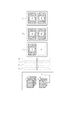
ここでは図3に示されるように、A4サイズ(210mm×297mm)のシートに、4枚の画像を同時に出力(4in1)し、その後に図3のH1〜H4、V1〜V4の計8箇所を裁断し、L版サイズ(89mm×127mm)4枚に仕上げる場合を例示する。 Here, as shown in FIG. 3, four images are simultaneously output (4 in 1) to an A4 size (210 mm × 297 mm) sheet, and thereafter, a total of eight positions H1 to H4 and V1 to V4 in FIG. The case where it cuts and finishes to L plate size (89mm x 127mm) 4 sheets is illustrated.
ベルト定着装置3からシート排出ロール対37により排出されたシートは、中継パス51を通って、裁断装置4に送り込まれる。
The sheet discharged from the
その後、シートは裁断入り口ローラ46によりホイール式カッター41〜44、およびギロチン式カッター45の方向へ進入する。
Thereafter, the sheet enters the wheel cutters 41 to 44 and the
シートの先端がシート検知センサ48で検知されてから所定時間が経過すると、裁断入り口ローラ46のシート搬送動作が停止する。その停止状態においてギロチン式カッターの可動歯可動歯45aが下降移動してそのカッターの固定歯45bとそれぞれ近接交差した後、再び上昇して退避する。
When a predetermined time elapses after the leading edge of the sheet is detected by the
これにより、図3に示すV1の裁断線の位置にてシートが裁断される。 As a result, the sheet is cut at the position of the cutting line V1 shown in FIG.
ギロチン式カッター45によるV1位置での裁断が終了すると、裁断入り口ローラ46のシート搬送動作が再開される。
When the cutting at the V1 position by the
同様に、V2〜V4の裁断線においても、ギロチン式カッターの可動歯可動歯45aが下降移動して裁断後、再び上昇して退避、という動作を繰り返す。
Similarly, on the cutting line V2 to V4, the movable tooth
また、搬送方向に対して平行方向である裁断位置H1〜H4においては、シートが装置内を搬送され、裁断位置H1〜H4に対応したホイール式カッター41〜44を通過することで裁断される。 In the cutting positions H1 to H4 that are parallel to the conveying direction, the sheet is conveyed through the apparatus and is cut by passing through the wheel cutters 41 to 44 corresponding to the cutting positions H1 to H4.
この例では、ホイール式カッター41〜44の配置関係により、ギロチン式カッター45によるシートの裁断が行われる時点でもホイール式カッター41〜44による裁断は進行途中である。
In this example, due to the arrangement relationship of the wheel cutters 41 to 44, the cutting by the wheel cutters 41 to 44 is still in progress even when the sheet is cut by the
ホイール式カッター41〜44を通過した後の裁断されたシートは、裁断出口ローラ47により排出トレイ52上に排出される。このとき、排出トレイ上52では、裁断が行われた順に2列になって積載されることになる。
The cut sheet after passing the wheel cutters 41 to 44 is discharged onto the
なお、ホイール式カッター41〜44も様々な裁断に対応できるように、ギロチン式カッター45同様、非裁断時は上昇することが望ましく、さらには41、44と42、43は独立して上下に退避できるように構成することがより望ましい。
In addition, like the
もちろん、図3ではホイールカッター41、44と42、43を同軸上に設けているが、同軸上でなくても構わない。
Of course, although the
ここで、例えば名刺やハガキといった、同一画像を連続して出力する場合は画像の割り付け順を考慮しなくて良い。 Here, for example, when outputting the same image continuously, such as a business card or a postcard, it is not necessary to consider the order of image allocation.
しかしながら、写真などのページ順(画像順)が決まっている画像を出力する場合は正しく面割付けをおこなわないと、トレイ上の積載順がばらばらになってしまう。 However, in the case of outputting an image in which the page order (image order) such as a photo is determined, the stacking order on the tray will be dispersed unless the surface layout is performed correctly.
よって、2列になって積載された出力紙のページ順を、その列の中で順番通りに並べて出力されることが望ましい。さらに、その2列になった出力紙をふたつ重ねれば最終的にページ順になっていることが望ましい。 Therefore, it is desirable to output the page order of the output sheets stacked in two rows in order in the row. Furthermore, it is desirable that the two sheets of output paper in the two rows are finally arranged in page order.
また、総出力数(総画像枚数)が4の倍数であれば問題ないが、そうでない場合は全出力紙中の何枚かは白紙として出力されることになる。 Further, there is no problem if the total number of outputs (total number of images) is a multiple of 4, but if this is not the case, some of all the output sheets are output as blank sheets.
最終的に重ねた出力紙の途中に白紙が入るのは非常に煩わしく、白紙は全出力紙中の最後にまとまっているのが望ましい。 It is very troublesome for the blank paper to enter the middle of the output paper that is finally stacked, and it is desirable that the blank paper is gathered at the end of all the output paper.
以上の目的を達成するための最適な画像の割り付けについて、例を用いて説明する。なお、画像の割り付けは、操作パネルPに写真プリントモードが選択されたことに基づいて制御部Cが行う。以下に詳細に例示する画像の割り付けは、プリントジョブ中の画像枚数等に応じて制御部Cが行う。決定された画像の割り付けに基づいて1枚のシート上に複数の画像を形成する画像形成を複数のシートに対して行なうように制御部Cはプリント部1の各部を制御する。まず図17に画像割付けを決定するためのフローチャートを示す。
An optimal image allocation for achieving the above object will be described using an example. The image allocation is performed by the control unit C based on the selection of the photo print mode on the operation panel P. The image allocation illustrated in detail below is performed by the control unit C in accordance with the number of images in the print job. Based on the determined image assignment, the control unit C controls each part of the
ユーザによるモード選択(S101)によって写真プリントモードが選択されると(S102)、まず画像の取り込みがおこなわれる(S103)。 When the photo print mode is selected by the user's mode selection (S101) (S102), first, an image is captured (S103).
画像の取り込みは、上述したように、パソコンなどの外部機器からの出力画像でもよいし、リーダ部2において読み取った画像でもよい。
As described above, the image may be captured by an output image from an external device such as a personal computer or an image read by the
もしくは、外部メモリー等にファイルされた画像であってもよい。 Alternatively, it may be an image filed in an external memory or the like.
画像の取り込みが終了すると、L版や2L版といった、出力画像のサイズを設定する(S104)。 When the image capture is completed, the size of the output image such as the L version or the 2L version is set (S104).
その後、シートサイズの選択がおこなわれる。なお、出力画像のサイズの設定はユーザが操作パネルを操作して行なわれる。この際、写真プリント用記録紙が1種類であれば自動的にそれが選択される。画像のサイズに適したシートサイズを自動で選択モードかユーザによって選択モードかを判断する(S105)。ユーザが選択するモードであったならば複数種類あれば、ユーザが任意に操作部から選択する(S106)。 Thereafter, the sheet size is selected. The size of the output image is set by the user operating the operation panel. At this time, if there is only one type of photo print recording paper, it is automatically selected. It is determined whether the sheet size suitable for the image size is automatically selected mode or selected by the user (S105). If the mode is selected by the user, if there are a plurality of types, the user arbitrarily selects from the operation unit (S106).
シートサイズが選択されると、上記情報に基づき、装置の制御部Cにおいて、画像のレイアウトが自動的に決定される(S107)。この画像のレイアウトについては後に詳述する。 When the sheet size is selected, the image layout is automatically determined by the control unit C of the apparatus based on the information (S107). The layout of this image will be described in detail later.
装置が決定したレイアウトでOKであれば(S108)、そのコマンドを選択すればよいし、もし気に入らなければキャンセルすることもできる。 If the layout determined by the apparatus is OK (S108), the command can be selected, or can be canceled if the user does not like it.
キャンセルの場合は、再度設定画面に戻ることになる。 In case of cancellation, the setting screen is displayed again.
次に、画像の割り付けについて、例を挙げて以下に説明する。 Next, image allocation will be described below with an example.
図4にL版を12枚出力する例を示す。 FIG. 4 shows an example of outputting 12 L versions.
使用するシートをA4サイズとする。A4サイズにはL版の画像を4枚貼り付けることができる。したがって、使用されるA4サイズのシートは3枚である。 The sheet to be used is A4 size. Four L-size images can be pasted on the A4 size. Therefore, three A4 size sheets are used.
P1、P2、P3はプリンタ部1の定着ユニット6を通過した後のシート順を示すものであり、P1〜P3の中に割り付けられた画像をそのページ順(画像順)に(1)〜(12)として記している。
P1, P2, and P3 indicate the sheet order after passing through the fixing
図4における20、3、4、52は上述のシート反転パス20、ベルト定着装置3、裁断装置4、排出トレイ52をそれぞれ模式的に描いたものである。
4, 20, 3, 4, and 52 schematically depict the
本実施形態ではシート反転パス20にてシートの表裏が反転するため、裁断装置4の排出トレイ52上の出力紙は裏面を向いている。
In this embodiment, since the front and back of the sheet are reversed in the
シートの上側の列では(2)、(1)、(4)、(3)、(6)、(5)の順になるように割り付けると、排紙トレイ52上では画像を下向きにして(1)から(6)までが順番通りに整列する。 In the upper row of the sheets, when the sheets are assigned in the order of (2), (1), (4), (3), (6), (5), the image is directed downward on the discharge tray 52 (1 ) To (6) are arranged in order.
同様に、下側の列では(8)、(7)、(10)、(9)、(12)、(11)の順になるように面を割り付けると、排紙トレイ52上では画像を下向きにして(7)から(12)までが順番通りに整列する。
Similarly, when the planes are assigned in the order of (8), (7), (10), (9), (12), and (11) in the lower row, the image is directed downward on the
つまりプリント部1において一枚目のシートP1においてはまず(2)、(8)の画像を夫々シートの上下に形成し、引き続き(1)、(7)の画像を夫々シートの上下に形成する。二枚目のシートP2においてはまず(4)、(10)の画像を夫々シートの上下に形成し、引き続き(3)、(9)の画像を夫々シートの上下に形成する。三枚目のシートP3においてはまず(6)、(12)の画像を夫々シートの上下に形成し、引き続き(5)、(11)の画像を夫々シートの上下に形成する。
That is, on the first sheet P1 in the
ジョブ完了後、即ち、排紙トレイ52上にはシートが積載されたときには、排紙トレイ52上にページ順に積載されたシートの束が二つつくられる。つまり、排紙トレイ52上には、2つの列で積載されるが、2つの列において両者ともに画像順が連続して積載される。さらに、排紙トレイ52上につくられた2つの束を重ねるだけで、最終的には(1)から(12)までのL版写真が順番通りに整列する。
After the job is completed, that is, when sheets are stacked on the
同様に、図5〜図7はA4サイズ3枚にL版を11〜9枚出力する例を夫々示している。 Similarly, FIGS. 5 to 7 show examples of outputting 11 to 9 L plates for 3 sheets of A4 size.
このとき、白紙画像になるところにはWの記号を記してある。 At this time, a W symbol is marked where a blank image is to be formed.
図5〜図7のように面割付けをおこなうことにより、最終的なページ順が揃うばかりでなく、白紙部分がページの最後にまとまって出力できる。 By performing surface layout as shown in FIGS. 5 to 7, not only the final page order is aligned, but also blank pages can be output together at the end of the page.
図18乃至図20は、A4サイズ3枚にL版を11〜9枚出力する際の画像割り付けの別例を夫々示している。 FIGS. 18 to 20 show other examples of image allocation when outputting 11 to 9 L plates for 3 sheets of A4 size.
図18〜図20に示した画像の割り付け方法であっても、最終的に排紙トレイ52にページ順が揃った状態で積載されるばかりでなく、白紙部分がまとまって出力できる。図18〜図20に示した例では、白紙となるシートが先頭ページ側にまとまって出力される。
In the image allocation methods shown in FIGS. 18 to 20, not only the pages are finally stacked on the
図6および図7に示した例、図19及び図20に示した例のように、白紙部分が複数枚となる場合に、白紙部分を考慮した画像の割り付けを行うことによって排出トレイ52に積載されるシート束に白紙シートが固まって排出されるためにユーザが白紙を取り除くのがよういとなる。
As shown in the examples shown in FIGS. 6 and 7 and the examples shown in FIGS. 19 and 20, when there are a plurality of blank pages, the images are loaded on the
図8はA4サイズ3枚に2L版を6枚出力する例を示している。 FIG. 8 shows an example in which six 2L versions are output for three A4 size sheets.
ここでも、上側の列で(1)、(2)、(3)の順に、下側の列では(4)、(5)、(6)の順になるように面を割り付けると、ジョブ完了後、排紙トレイ52上の2列をふたつ重ねることにより、最終的には(1)から(6)までの2L版写真が順番通りに整列する。
Again, if the faces are assigned in the order of (1), (2), (3) in the upper row and (4), (5), (6) in the lower row, By overlapping two rows on the
同様に、図9はA4サイズ3枚に2L版を5枚出力する例を示している。 Similarly, FIG. 9 shows an example in which five 2L versions are output for three A4 sizes.
このとき、白紙画像になるところにはWの記号を記してある。 At this time, a W symbol is marked where a blank image is to be formed.
図9のように面割付けをおこなうことにより、最終的なページ順が揃うばかりでなく、白紙部分がページの最後に出力できる。 By performing surface layout as shown in FIG. 9, not only the final page order is aligned, but a blank page portion can be output at the end of the page.
以上、図4〜図9を用いて画像の面割付けを説明したが、ここで挙げた例に限らず、シートの大きさのデータと出力される画像の大きさのデータ、出力される画像の数のデータが決定されれば、重ね合わせた後に順番通りに揃い、かつ白紙が最後尾にくるような最適な面割付けが選択できる。 The image layout has been described above with reference to FIGS. 4 to 9. However, the present invention is not limited to the example given here, and the sheet size data, the output image size data, and the output image If the number of data is determined, it is possible to select an optimal surface layout that aligns in order after superposition and that the blank paper comes to the end.
例えばL版をA3サイズのシートに面割付した場合、幅方向2列×搬送方向4=8枚よりも、幅方向3列×搬送方向3=9枚の方が画像数を多く割り付けられる。
For example, when the L plate is assigned to an A3 size sheet, the number of images is more allocated in the
よって、裁断装置を3列に裁断可能に構成しておけば、より高効率な出力が期待できる。 Therefore, if the cutting device is configured to be capable of cutting in three rows, a more efficient output can be expected.
3列の裁断をおこなうためには、図3における、ホイール式カッターの数を増やすことで容易に構成できるが、この場合も独立して設けることがより望ましい。 In order to cut three rows, it can be easily configured by increasing the number of wheel cutters in FIG. 3, but it is more desirable to provide them independently in this case as well.
また、L版や2L版といった従来の写真サイズに限定せず、シートを3×3=9分割、4×4=16分割といった小サイズに指定して裁断しる場合においても、同様に扱えばよい。 Further, the present invention is not limited to the conventional photo size such as the L plate or the 2L plate, and the sheet can be cut in the same manner even when the sheet is specified as a small size such as 3 × 3 = 9 divisions and 4 × 4 = 16 divisions. Good.
一般的には以下のように考えればよい。 In general, the following should be considered.
シートの横サイズをX、シート縦サイズをYとした場合を考える。 Consider the case where the horizontal size of the sheet is X and the vertical size of the sheet is Y.
切断代や前後余白、左右余白を考慮すると、実際に印刷可能な範囲はそれぞれX’、Y'となる。 Considering the cutting allowance, the front and rear margins, and the left and right margins, the actual printable ranges are X ′ and Y ′, respectively.
出力する画像の大きさが、横サイズをx、縦サイズをyとした場合、シート1枚に印刷可能な縦横それぞれの数は
a×x<=X'<(a+1)x
b×y<=Y'<(b+1)y a、bは整数
となり、このレイアウトにおける最大画像数N1はこれらの積a×bで与えられる。
When the size of the output image is x for the horizontal size and y for the vertical size, the number of vertical and horizontal printable on one sheet is a × x <= X ′ <(a + 1) x
b × y <= Y ′ <(b + 1) y a and b are integers, and the maximum number of images N1 in this layout is given by the product a × b.
また、レイアウトは縦と横を入れ替えても構わないので、同様に考えると、
a'×x<=Y'<(a'+1)x
b’×y<=X'<(b'+1)y a’、b’は整数
となり、このレイアウトにおける最大画像数N2はこれらの積a’×b’で与えられることになる。
Also, the layout can be swapped vertically and horizontally, so if you think in the same way,
a ′ × x <= Y ′ <(a ′ + 1) x
b ′ × y <= X ′ <(b ′ + 1) y a ′ and b ′ are integers, and the maximum number of images N2 in this layout is given by these products a ′ × b ′.
この2式で与えられたN1とN2を比較し、より大きな方を1枚あたりの最大印刷可能数Nとすればよい。 N1 and N2 given by these two formulas are compared, and the larger one may be set as the maximum printable number N per sheet.
もちろん、装置の制約により、a〜dには上限があるが、その際はその制約を上式に加えた後に、上記式により比較をおこなえばよい。最大画像数Nとシートサイズに応じて一枚のシートにおける画像の割り当て位置は予め設定されている。 Of course, there is an upper limit for a to d due to the restrictions of the apparatus, but in that case, after adding the restrictions to the above equation, the comparison may be made by the above equation. In accordance with the maximum number of images N and the sheet size, the image assignment position in one sheet is set in advance.
また、上述のように、出力画像サイズとシートサイズが決定されると、最大画像数Nが決定されるが、出力される画像の数をMとした場合、必要なシート枚数は下式を満足するαであらわされる。 As described above, when the output image size and the sheet size are determined, the maximum number of images N is determined. However, when the number of output images is M, the required number of sheets satisfies the following formula. Is expressed by α.
αN<=M<(α+1)N (α、N、Mは整数)
なお、このとき
W=αN−M
で与えられるWが余白画像となって出力されることになる。
αN <= M <(α + 1) N (α, N and M are integers)
At this time, W = αN−M
W is given as a blank image and output.
N、Mが決定されると、図4等で説明したように、積載後のページ順が揃うように一意的に画像レイアウトが決定される。 When N and M are determined, as described with reference to FIG. 4 and the like, the image layout is uniquely determined so that the page order after loading is aligned.
言い換えれば、レイアウトされた画像のすべての位置に対してページ順が揃うように番号が割り振られる。 In other words, numbers are assigned so that the page order is aligned for all positions of the laid out images.
よって、出力される画像の数をMとした場合は、番号がMまでは画像として出力され、M+1で与えられる番号からN×αで与えられる番号までは白紙で出力されることになる。 Therefore, when the number of images to be output is M, images up to M are output as images, and blank numbers are output from a number given by M + 1 to a number given by N × α.
つまり、排出トレイ上の複数の列で画像順に並べるように、画像形成装置は、画像順の連続した複数の画像を複数のシート上に形成し、一枚のシートに複数の画像を形成可能な画像形成部を有する。更に、画像形成装置は、画像形成部によって画像が形成されたシートを搬送する搬送部と、搬送部によるシート搬送方向に沿う方向に、前記搬送部によって搬送されるシート毎に裁断する裁断装置とを有する。画像形成装置は、更に、前記裁断装置によって裁断された裁断後シートが複数列で積載される排出トレイと、を有する。そして、画像形成装置は、連続した複数の画像を、前記裁断装置により裁断される前の複数のシート上に割り当てる際、前記排出トレイに複数列で積載された裁断後シートの束の画像順が前記複数の列において連続するように割り当てて画像形成するように前記画像形成部を制御する制御部と、を有する。このような画像形成装置の構成によってもよい。 In other words, the image forming apparatus can form a plurality of continuous images in the order of images on a plurality of sheets and form a plurality of images on a single sheet so that the images are arranged in a plurality of rows on the discharge tray. An image forming unit is included. Further, the image forming apparatus includes a conveying unit that conveys a sheet on which an image is formed by the image forming unit, and a cutting device that cuts each sheet conveyed by the conveying unit in a direction along a sheet conveying direction by the conveying unit. Have The image forming apparatus further includes a discharge tray on which the cut sheets cut by the cutting apparatus are stacked in a plurality of rows. When the image forming apparatus allocates a plurality of consecutive images on a plurality of sheets before being cut by the cutting apparatus, the image order of a bundle of cut sheets stacked in a plurality of rows on the discharge tray is determined. A control unit that controls the image forming unit so as to form images by assigning them continuously in the plurality of columns. Such a configuration of the image forming apparatus may be employed.
(第2実施形態)
上記実施形態1では、ベルト定着装置3のベルト面に画像面を対向させるためシート反転部20にてシートの表裏が反転させている。よって排紙トレイ52上で画像面が下を向いているため、オペレーターには出力紙の状態が確認しづらい構成となっている。
(Second Embodiment)
In the first embodiment, the
本第2実施形態2では図10に示すように、実施例1で中継パスを設けたところに、再度反転させるための反転パス54を設けた。この点が第1実施形態との違いである。
In the
つまり、シートがベルト定着装置3から排出されるときは画像面を下向きにしているが、反転パス54にて、画像面を再度上に向けて裁断装置4に送り込むので、結果的に排紙トレイ52上は出力紙は画像を上向きにして排出されることになる。
That is, when the sheet is discharged from the
図11に本第2実施形態においてL版を12枚出力する例を示す。 FIG. 11 shows an example of outputting 12 L plates in the second embodiment.
使用されるシートはA4サイズ3枚である。 Three sheets of A4 size are used.
P1、P2、P3はプリンタ部1の定着ユニット6を通過した後のシート順を示すものである。P1〜P3の中に割り付けられた画像をそのページ順に(1)〜(12)として記している。
P1, P2, and P3 indicate the sheet order after passing through the fixing
20、3、4、52は同様にシート反転部、ベルト定着装置、裁断装置、排出トレイをそれぞれ模式的に描いたものであるが、ここにも反転パス52の模式図を追加している。
20, 3, 4, and 52 are each schematically depicted a sheet reversing unit, a belt fixing device, a cutting device, and a discharge tray, respectively, but a schematic diagram of the reversing
P1の上側の列では(6)、(5)、(4)、(3)、(2)、(1)の順になるように割り付けると、排紙トレイ52上では画像を上向きにして(1)から(6)までが順番通りに整列する。 In the upper row of P1, when the images are assigned in the order of (6), (5), (4), (3), (2), (1), the image is directed upward on the paper discharge tray 52 (1 ) To (6) are arranged in order.
同様に、下側の列では(12)、(11)、(10)、(9)、(8)、(7)の順になるように面を割り付けると、排紙トレイ52上では画像を下向きにして(7)から(12)までが順番通りに整列する。
Similarly, in the lower row, when the planes are assigned in the order of (12), (11), (10), (9), (8), (7), the image is directed downward on the
よって、ジョブ完了後、排紙トレイ52上の2列をふたつ重ねることにより、最終的には(1)から(12)までのL版写真が順番通りに整列する。
Therefore, after the job is completed, by overlapping two rows on the
同様に、図12〜図14はA4サイズ3枚にL版を11〜9枚出力する例を示している。 Similarly, FIGS. 12 to 14 show an example in which 11 to 9 L plates are output on 3 sheets of A4 size.
このとき、白紙画像になるところにはWの記号を記してある。 At this time, a W symbol is marked where a blank image is to be formed.
図12〜図14のように面割付けをおこなうことにより、最終的なページ順が揃うばかりでなく、白紙部分がページの最後にまとまって出力できる。 By performing the surface layout as shown in FIGS. 12 to 14, not only the final page order is aligned, but also blank pages can be output together at the end of the page.
図15はA4サイズ3枚に2L版を6枚出力する例を示している。 FIG. 15 shows an example of outputting six 2L versions for three A4 sizes.
ここでも、上側の列で(3)、(2)、(1)の順に、下側の列では(6)、(5)、(4)の順になるように面を割り付けると、ジョブ完了後、排紙トレイ52上の2列をふたつ重ねることにより、最終的には(1)から(6)までの2L版写真が順番通りに整列する。
Again, if the faces are assigned in the order of (3), (2), (1) in the upper row and (6), (5), (4) in the lower row, By overlapping two rows on the
同様に、図16はA4サイズ3枚に2L版を5枚出力する例を示している。 Similarly, FIG. 16 shows an example of outputting five 2L versions for three A4 sizes.
このとき、白紙画像になるところにはWの記号を記してある。 At this time, a W symbol is marked where a blank image is to be formed.
図16のように面割付けをおこなうことにより、最終的なページ順が揃うばかりでなく、白紙部分がページの最後に出力できる。 By performing the surface layout as shown in FIG. 16, not only the final page order is arranged, but also a blank page portion can be output at the end of the page.
以上、図11〜図16を用いて画像の面割付けを説明したが、第1実施形態同様、シートの大きさのデータと出力される画像の大きさのデータ、出力される画像の数のデータが決定されれば、重ね合わせた後に順番通りに揃い、かつ白紙が最後尾にくるような最適な面割付けが選択できる。 The image layout has been described above with reference to FIGS. 11 to 16. However, as in the first embodiment, sheet size data, output image size data, and output image number data are provided. Is determined, it is possible to select an optimal surface layout that aligns in order after overlapping and that the blank paper comes to the end.
上記の実施形態いずれでも、オペレーターが出力後にページ順を揃えなおしたり、出力紙の中から白紙を探して抜き取るような面倒を排除することが可能となる。 In any of the above-described embodiments, it is possible to eliminate the trouble of the operator rearranging the page order after output, or searching for and removing blank paper from the output paper.
(第3実施形態)
発明の第3実施形態を説明する。プリンタ部1から画像面を上にした状態で、光沢処理装置305に供給されることと、光沢処理装置305の搬送パス形状が第1実施形態と異なる。第3実施形態を示す図21においては第1実施形態と同一の部材については同一の符号を付して説明を省略する。重複した説明を避けるために第1実施形態と異なる点を以下に詳述し第1実施形態と同様の構成については詳細な説明を省略する。
(Third embodiment)
A third embodiment of the invention will be described. The
プリンタ部301の定着装置6を通過して画像が定着されたシートは、縦パス307を経て光沢処理装置305に画像面を上にした状態で搬送される。光沢処理装置305に搬送されたシートは受け入れパス315を通過する。受け入れパス315にはシートを搬送する搬送ローラ315a、315bが設けられている。受け入れパスの下流側にはベルト定着パス351が設けられている。ベルト定着パス351には搬送ローラ351a、351bと、ベルト定着器3と、が設けられている。ベルト定着器3は実施形態1で説明した構成と同様のものを傾けて配置してある。ベルト定着器3の下流側には裁断装置4が設けられている。
The sheet on which the image is fixed by passing through the fixing
裁断装置4によって裁断されたシートは排出トレイ352に排出される。排出トレイ352上では画像面を上にして積載される。なお、ベルト定着器3を通過しない場合(通常プリントモードの場合)にはシートは排出トレイ319に排出される。
The sheet cut by the
本形態における画像の割り付け例について説明する。 An example of image allocation in this embodiment will be described.
図22に本第3実施形態においてL版を12枚出力する例を示す。使用されるシートはA4サイズ3枚である。 FIG. 22 shows an example of outputting 12 L plates in the third embodiment. Three sheets of A4 size are used.
P1、P2、P3はプリンタ部1の定着ユニット6を通過した後のシート順を示すものである。P1〜P3の中に割り付けられた画像をそのページ順に(1)〜(12)として記している。
P1, P2, and P3 indicate the sheet order after passing through the fixing
(第4実施形態)
発明の第4実施形態を説明する。プリンタ部1から画像面を上にした状態で、光沢処理装置405に供給されることと、光沢処理装置405の搬送パス形状が第1実施形態と異なる。第4実施形態を示す図23においては第1実施形態と同一の部材については同一の符号を付して説明を省略する。重複した説明を避けるために第1実施形態と異なる点を以下に詳述し第1実施形態と同様の構成については詳細な説明を省略する。
(Fourth embodiment)
A fourth embodiment of the invention will be described. The
プリンタ部401の定着装置6を通過して画像が定着されたシートは、縦パス307を経て光沢処理装置305に画像面を上にした状態で搬送される。光沢処理装置403搬送されたシートはベルト定着装置5によって再度画像が定着される。このベルト定着器3は実施形態1で説明した構成と同様のものを反対向けにして配置してある。ベルト定着器3の下流側には裁断装置4が設けられている。裁断装置4によって裁断されたシートは排出パス415を通過して排出トレイ452に排出される。排出パス415にはシートを搬送する搬送ローラ415a、415bおよび排出ローラ415cが設けられている。排出パス415は湾曲形状をなしシートの表裏を反転する。したがって、排出トレイ上ではシートは画像面を裏側として排出される。
The sheet on which the image has been fixed by passing through the fixing
本形態における画像の割り付け例について説明する。 An example of image allocation in this embodiment will be described.
図23に本第4実施形態においてL版を12枚出力する例を示す。使用されるシートはA4サイズ3枚とした場合について説明する。 FIG. 23 shows an example of outputting 12 L plates in the fourth embodiment. The case where the sheets used are three A4 sizes will be described.
P1、P2、P3はプリンタ部1の定着ユニット6を通過した後のシート順を示すものである。P1〜P3の中に割り付けられた画像をそのページ順に(1)〜(12)として記している。
P1, P2, and P3 indicate the sheet order after passing through the fixing
なお、上述のいずれの実施形態においてもA4サイズ(210mm×297mm)のシートに、L版サイズ(89mm×127mm)の画像4つを割り付ける例を主に説明した。しかし、はがきKGサイズ(102mm×152mm)の画像を4つ割り付けるためにA4サイズよりも大き目のサイズ(例えば、216mm×320mm)のシートをプリンタ部1に供給してもよい。
In any of the above-described embodiments, an example in which four images of L size (89 mm × 127 mm) are allocated to an A4 size (210 mm × 297 mm) sheet has been mainly described. However, a sheet having a size larger than the A4 size (for example, 216 mm × 320 mm) may be supplied to the
1 プリンタ部
3 ベルト定着装置
4 裁断装置
5 光沢処理装置
6 定着ユニット
19 排出トレイ
31 加熱ロール
34 定着ベルト
36 冷却器
41〜44 ホイール式カッター
45 ギロチン式カッター
51 中継パス
52 排出トレイ
54 反転パス
DESCRIPTION OF
Claims (3)
前記画像形成部によって画像が形成されたシートを搬送する搬送部と、
前記搬送部によるシート搬送方向に沿う方向と前記シート搬送方向と垂直な方向とに、前記搬送部によって搬送されるシート毎に裁断する裁断装置と、
前記裁断装置によって裁断された裁断後シートが複数列で積載される排出トレイと、
前記画像順が連続した複数の画像を、前記裁断装置により裁断される前の複数のシート上に割り当てる際、前記排出トレイに複数列で積載された裁断後シートの束の画像順が前記複数の列において連続するように割り当てて画像形成するように前記画像形成部を制御する制御部と、を有し、
前記裁断装置によって裁断された裁断後シートに複数の白紙が発生する場合、前記排紙トレイ上の複数列のうちの一つの列に複数の白紙が配置され、且つ、前記排紙トレイ上に積載された複数列の出力紙を、ページ順が連続するように上下方向に積み重ねたとき、連続したページの先頭側または最後尾側に前記複数の白紙が集結するように、前記画像形成部を前記制御部が制御することを特徴とする画像形成装置。 An image forming unit that can form a plurality of images on a single sheet and allocates a plurality of images in a sequence of images to a plurality of sheets, and conveys the sheet on which the image is formed by the image forming unit A transport section;
A cutting device for cutting each sheet conveyed by the conveyance unit in a direction along the sheet conveyance direction by the conveyance unit and in a direction perpendicular to the sheet conveyance direction;
A discharge tray on which sheets after cutting cut by the cutting device are stacked in a plurality of rows;
When assigning the plurality of images in which the image order is continuous onto the plurality of sheets before being cut by the cutting device, the image order of the bundle of sheets after cutting stacked in a plurality of rows on the discharge tray is the plurality of images. and a control unit which controls the image forming unit so as to image formation by assigning so as to be continuous in the column, was closed,
When a plurality of blank sheets are generated on the cut sheet cut by the cutting apparatus, a plurality of blank sheets are arranged in one of the plurality of columns on the discharge tray and stacked on the discharge tray. The plurality of rows of output sheets are stacked in the vertical direction so that the page order is continuous, and the image forming unit is configured so that the plurality of blank sheets are collected on the leading side or the trailing side of the continuous pages. An image forming apparatus controlled by a control unit .
回転する表面平滑な無端状のベルトと、前記無端状のベルトの表面に、画像を担持するシートをその像担持面がベルト表面と対向する状態で加熱および加圧して密着させる加熱加圧手段とを有する光沢付与装置を前記裁断装置の上流側前に配置したことを特徴とする請求項1に記載の画像形成装置。 The image forming unit is an electrophotographic image forming unit that forms an image on a recording sheet by transferring and fixing the toner image carried by the image carrier onto the recording sheet being conveyed;
An endless belt with a smooth surface that rotates, and a heating and pressurizing unit that heats and presses the sheet carrying an image on the surface of the endless belt in a state where the image carrying surface faces the belt surface. The image forming apparatus according to claim 1, wherein a gloss imparting device having a surface is disposed upstream of the cutting device.
1枚のシートに割り当てられた4つの画像毎に前記裁断装置はシートを裁断し、
前記4つの画像は、シートの搬送方向に沿った前記裁断装置の裁断によって2つの画像づつに分けられ、
前記シートの搬送方向に沿った裁断によって分けられた前記2つの画像の一方はいずれも前記排出トレイにおける第1列に積載され、前記2つの画像の他方はいずれも前記排出トレイにおける第2の列に積載され、
前記第1列に積載された裁断後シートは画像順が連続し、前記第2列に積載された裁断後シートは画像順が連続することを特徴とする請求項1または2に記載の画像形成装置。 The image forming unit is capable of forming four images of the plurality of continuous images on a single sheet, and forming the plurality of continuous images by forming four images on the plurality of sheets. Forming,
The cutting device cuts the sheet for every four images assigned to one sheet,
The four images are divided into two images by cutting the cutting device along the sheet conveyance direction,
One of the two images separated by cutting along the sheet conveying direction is stacked in the first row of the discharge tray, and the other of the two images is the second row of the discharge tray. Loaded on the
3. The image formation according to claim 1, wherein the image order of the cut sheets stacked in the first row is continuous, and the image order of the cut sheets stacked in the second row is continuous. apparatus.
Priority Applications (1)
| Application Number | Priority Date | Filing Date | Title |
|---|---|---|---|
| JP2005265523A JP4641474B2 (en) | 2005-09-13 | 2005-09-13 | Image forming apparatus |
Applications Claiming Priority (1)
| Application Number | Priority Date | Filing Date | Title |
|---|---|---|---|
| JP2005265523A JP4641474B2 (en) | 2005-09-13 | 2005-09-13 | Image forming apparatus |
Publications (3)
| Publication Number | Publication Date |
|---|---|
| JP2007078996A JP2007078996A (en) | 2007-03-29 |
| JP2007078996A5 JP2007078996A5 (en) | 2010-04-30 |
| JP4641474B2 true JP4641474B2 (en) | 2011-03-02 |
Family
ID=37939407
Family Applications (1)
| Application Number | Title | Priority Date | Filing Date |
|---|---|---|---|
| JP2005265523A Expired - Fee Related JP4641474B2 (en) | 2005-09-13 | 2005-09-13 | Image forming apparatus |
Country Status (1)
| Country | Link |
|---|---|
| JP (1) | JP4641474B2 (en) |
Families Citing this family (1)
| Publication number | Priority date | Publication date | Assignee | Title |
|---|---|---|---|---|
| JP5183351B2 (en) * | 2008-08-06 | 2013-04-17 | キヤノン株式会社 | Image forming apparatus |
Citations (2)
| Publication number | Priority date | Publication date | Assignee | Title |
|---|---|---|---|---|
| JP2001315398A (en) * | 2000-05-12 | 2001-11-13 | Ricoh Co Ltd | Print system |
| JP2005049530A (en) * | 2003-07-31 | 2005-02-24 | Fuji Photo Film Co Ltd | Electrophotographic image forming apparatus, image forming system and electrophotographic print |
-
2005
- 2005-09-13 JP JP2005265523A patent/JP4641474B2/en not_active Expired - Fee Related
Patent Citations (2)
| Publication number | Priority date | Publication date | Assignee | Title |
|---|---|---|---|---|
| JP2001315398A (en) * | 2000-05-12 | 2001-11-13 | Ricoh Co Ltd | Print system |
| JP2005049530A (en) * | 2003-07-31 | 2005-02-24 | Fuji Photo Film Co Ltd | Electrophotographic image forming apparatus, image forming system and electrophotographic print |
Also Published As
| Publication number | Publication date |
|---|---|
| JP2007078996A (en) | 2007-03-29 |
Similar Documents
| Publication | Publication Date | Title |
|---|---|---|
| US7529514B2 (en) | Image forming apparatus with multiple image heating nip portions | |
| JP2007052175A (en) | Image forming system, image processor, image forming apparatus, order accepting device, and image forming method | |
| JP2007065459A (en) | Image forming system and recording medium | |
| US7496308B2 (en) | Image transferring and forming apparatus | |
| JP2007102194A (en) | Printer and image forming method | |
| US7197271B2 (en) | Printer and image forming method providing selectable path for recording medium | |
| JP4641474B2 (en) | Image forming apparatus | |
| JP4579788B2 (en) | Sheet processing apparatus and image forming apparatus | |
| JP2003316208A (en) | Image forming apparatus | |
| JP2007021863A (en) | Printer | |
| JP2007038433A (en) | Slitting mechanism for image recorder | |
| US20070071528A1 (en) | Image recording apparatus | |
| JP4254184B2 (en) | Gloss processing apparatus and image forming apparatus | |
| JP2006137528A (en) | Cutting device, cutting method and printer | |
| JP2005193547A (en) | Printer and print system | |
| JP5173161B2 (en) | Fixing apparatus and image forming apparatus | |
| JPH1124462A (en) | Toner image heating device | |
| JP2007021872A (en) | Image recorder | |
| JP2007021927A (en) | Image recorder | |
| JP4652796B2 (en) | Image forming apparatus | |
| US20100247129A1 (en) | Image forming apparatus | |
| JP2006088453A (en) | Cutting device and method | |
| JP2005262409A (en) | Round blade pair cutter, both round blade pair cutter, cutting device and image forming device | |
| JP2007102177A (en) | Printer and image forming method | |
| JP2007031012A (en) | Image recording device |
Legal Events
| Date | Code | Title | Description |
|---|---|---|---|
| A521 | Written amendment |
Free format text: JAPANESE INTERMEDIATE CODE: A523 Effective date: 20080912 |
|
| A621 | Written request for application examination |
Free format text: JAPANESE INTERMEDIATE CODE: A621 Effective date: 20080912 |
|
| RD04 | Notification of resignation of power of attorney |
Free format text: JAPANESE INTERMEDIATE CODE: A7424 Effective date: 20100201 |
|
| A521 | Written amendment |
Free format text: JAPANESE INTERMEDIATE CODE: A523 Effective date: 20100311 |
|
| RD01 | Notification of change of attorney |
Free format text: JAPANESE INTERMEDIATE CODE: A7421 Effective date: 20100630 |
|
| A131 | Notification of reasons for refusal |
Free format text: JAPANESE INTERMEDIATE CODE: A131 Effective date: 20100817 |
|
| A521 | Written amendment |
Free format text: JAPANESE INTERMEDIATE CODE: A523 Effective date: 20101016 |
|
| TRDD | Decision of grant or rejection written | ||
| A01 | Written decision to grant a patent or to grant a registration (utility model) |
Free format text: JAPANESE INTERMEDIATE CODE: A01 Effective date: 20101124 |
|
| A01 | Written decision to grant a patent or to grant a registration (utility model) |
Free format text: JAPANESE INTERMEDIATE CODE: A01 |
|
| A61 | First payment of annual fees (during grant procedure) |
Free format text: JAPANESE INTERMEDIATE CODE: A61 Effective date: 20101129 |
|
| R150 | Certificate of patent or registration of utility model |
Free format text: JAPANESE INTERMEDIATE CODE: R150 |
|
| FPAY | Renewal fee payment (event date is renewal date of database) |
Free format text: PAYMENT UNTIL: 20131210 Year of fee payment: 3 |
|
| LAPS | Cancellation because of no payment of annual fees |