JP4641383B2 - Image forming apparatus - Google Patents
Image forming apparatus Download PDFInfo
- Publication number
- JP4641383B2 JP4641383B2 JP2004128329A JP2004128329A JP4641383B2 JP 4641383 B2 JP4641383 B2 JP 4641383B2 JP 2004128329 A JP2004128329 A JP 2004128329A JP 2004128329 A JP2004128329 A JP 2004128329A JP 4641383 B2 JP4641383 B2 JP 4641383B2
- Authority
- JP
- Japan
- Prior art keywords
- developer
- developing
- image
- developing sleeve
- carrier
- Prior art date
- Legal status (The legal status is an assumption and is not a legal conclusion. Google has not performed a legal analysis and makes no representation as to the accuracy of the status listed.)
- Expired - Fee Related
Links
Images


Classifications
-
- G—PHYSICS
- G03—PHOTOGRAPHY; CINEMATOGRAPHY; ANALOGOUS TECHNIQUES USING WAVES OTHER THAN OPTICAL WAVES; ELECTROGRAPHY; HOLOGRAPHY
- G03G—ELECTROGRAPHY; ELECTROPHOTOGRAPHY; MAGNETOGRAPHY
- G03G15/00—Apparatus for electrographic processes using a charge pattern
- G03G15/06—Apparatus for electrographic processes using a charge pattern for developing
- G03G15/08—Apparatus for electrographic processes using a charge pattern for developing using a solid developer, e.g. powder developer
- G03G15/0806—Apparatus for electrographic processes using a charge pattern for developing using a solid developer, e.g. powder developer on a donor element, e.g. belt, roller
- G03G15/0813—Apparatus for electrographic processes using a charge pattern for developing using a solid developer, e.g. powder developer on a donor element, e.g. belt, roller characterised by means in the developing zone having an interaction with the image carrying member, e.g. distance holders
-
- G—PHYSICS
- G03—PHOTOGRAPHY; CINEMATOGRAPHY; ANALOGOUS TECHNIQUES USING WAVES OTHER THAN OPTICAL WAVES; ELECTROGRAPHY; HOLOGRAPHY
- G03G—ELECTROGRAPHY; ELECTROPHOTOGRAPHY; MAGNETOGRAPHY
- G03G2215/00—Apparatus for electrophotographic processes
- G03G2215/06—Developing structures, details
- G03G2215/0634—Developing device
- G03G2215/0636—Specific type of dry developer device
- G03G2215/0648—Two or more donor members
Description
本発明は、電子写真方式、静電記録方式等によって、像担持体上に形成された静電潜像を現像して可視画像を形成する現像装置を備えた複写機、プリンタ、記録画像表示装置、ファクシミリ等の画像形成装置に関するものである。 The present invention is an electrophotographic method, the electrostatic recording method, or the like, a copying machine provided with a developing equipment to form a visible image by developing the electrostatic latent image formed on an image bearing member, a printer, a recorded image display The present invention relates to an image forming apparatus such as an apparatus or a facsimile.
従来、電子写真方式や静電記録方式を用いた複写機等の画像形成装置では、感光ドラム等の像担持体上に形成された静電潜像を、現像剤を付着させて可視像化して現像剤像(トナー像)を形成する現像装置が備えられている。現像装置が実施するこの現像動作には、大きく分けて、一成分現像方式と二成分現像方式とがあるが、ここではトナーとキャリアを含む二成分現像剤を用いる二成分現像方式を採用した従来例について説明する。 Conventionally, in an image forming apparatus such as a copying machine using an electrophotographic method or an electrostatic recording method, an electrostatic latent image formed on an image carrier such as a photosensitive drum is visualized by attaching a developer. And a developing device for forming a developer image (toner image). The developing operation performed by the developing device can be broadly divided into a one-component developing method and a two-component developing method. Here, a conventional two-component developing method using a two-component developer including a toner and a carrier is employed. An example will be described.
現像装置の基本構成として、現像剤を収容する現像容器にて構成され、現像容器の像担持体と対向する部分に開口部を有し、この開口部には、内部に非回転の磁界発生手段を内蔵した、回転自在の現像剤担持体、例えば現像スリーブや現像ローラがその周面を露出させて設置されている。この現像剤担持体が、内部の磁界発生手段の機能により、現像容器内の現像剤を汲み出し、回転によって、像担持体表面に現像剤を担持搬送し、現像バイアスが印加されて現像剤が像担持体表面に移動し、現像動作が行われる。 As a basic configuration of the developing device, the developing device is configured by a developing container for containing a developer, and has an opening in a portion facing the image carrier of the developing container. , A rotatable developer carrier, for example, a developing sleeve or a developing roller is installed with its peripheral surface exposed. The developer carrier pumps out the developer in the developing container by the function of the internal magnetic field generation means, and carries and transports the developer onto the surface of the image carrier by rotation, and a developing bias is applied to the developer. It moves to the surface of the carrier and a developing operation is performed.
こうした基本構成をとる二成分現像剤を収容する従来の現像装置では、先ず、第1の例として、図8に示すような、現像容器2に収容された二成分現像剤を攪拌しながら搬送し、現像容器2内を循環させる循環手段である第1の搬送スクリュー5と第2の搬送スクリュー6とを水平方向に2本配置している現像装置102の構成のものが多い。
In a conventional developing apparatus containing a two-component developer having such a basic configuration, first, as a first example, the two-component developer contained in the developing
現像装置102では、現像剤が収容される現像容器2に不図示の像担持体との対向部に開口部が設けられ、この開口部に回転体である現像スリーブ8が設けられている。そして、現像スリーブ8には、磁界発生手段であるマグネットローラ8aが、現像スリーブ8の回転に対して固定して内蔵されている。そして、現像容器2内部に現像剤攪拌部材(搬送部材)として設けられた2本の循環手段5、6のうち不図示の像担持体に近い方に位置する第1の搬送スクリュー5が、現像スリーブ8に現像剤を供給し、現像スリーブ8と像担持体との対向部である現像部を通過した後の現像剤を回収するために用いられる。又、第2の搬送スクリュー6は、現像スリーブ8から回収された現像剤と新しく補給された現像剤とを混合攪拌するために用いられる。
In the developing
一方、近年、複写機、プリンタ等の電子写真方式を用いた画像形成装置においては、省スペースを達成するために装置本体の小型化の要求が強くなっており、特に、フルカラー方式の画像形成装置においては、現像装置を複数用いるため、小型化の要望が強い。 On the other hand, in recent years, in an image forming apparatus using an electrophotographic method such as a copying machine or a printer, there has been a strong demand for downsizing of the main body of the apparatus in order to achieve space saving. However, since a plurality of developing devices are used, there is a strong demand for downsizing.
この問題を解決するため、図8に示す第1の構成を改良した第2の構成として、特許文献1に記載されたような、図9に示す構成の現像装置103が考案されている。この図9の現像装置103は、上記の現像スリーブ8を備えた基本構成に加え、現像剤の循環手段である2本の搬送スクリュー5、6を上下に配置したことが特徴である。
In order to solve this problem, as a second configuration obtained by improving the first configuration shown in FIG. 8, a developing
より詳細に説明すれば、現像装置103は現像剤を収容した現像容器2を備え、現像容器2の感光ドラム10と対面した開口部に現像剤担持体である現像スリーブ8を有している。そして、現像容器2内の開口部との反対側には隔壁7によって区画された現像室3と攪拌室4が上下に形成されており、これらの現像室3と攪拌室4内には現像剤を攪拌・搬送し、現像容器2内を循環させる循環手段として第1及び第2の搬送スクリュー5、6が、それぞれ設置されている。第1の搬送スクリュー5は現像室3内の現像剤を搬送し、又、第2の搬送スクリュー6は、トナー補給口(不図示)から攪拌室4内に第2の搬送スクリュー6の上流側に供給されるトナーと攪拌室4内に既にある現像剤とを攪拌しながら搬送し、現像剤のトナー濃度を均一化する。
More specifically, the developing
以上説明したように、図9に示した縦攪拌型の現像装置103は、現像室3と攪拌室4とが鉛直方向上下に配置されているため、その水平方向の占有スペースが小さくて済むという長所があり、例えば複数の現像装置を水平方向に並列搭載するタンデム方式等のカラー画像形成装置でも小型化が可能となる。又、現像スリーブ8への現像剤の提供を、現像スリーブ8回転方向下流側の現像室3で行い、回収を上流側の攪拌室4で行う、といったように現像スリーブ8に対する現像剤の提供と回収を別々の収容部にて行うことで、新しい現像剤が均一に混合された状態で現像スリーブ8に提供されるので、高画質化に貢献できる。
As described above, the vertical stirring
現像装置103は、縦攪拌型にすることによって小型化を実現してきたが、近年、二成分現像方式による現像装置に対して小型化以外にも、更なる高画質化、長寿命化の開発が進められている。特に、その中で二成分現像方式による現像装置の長寿命化を達成するためには、現像剤が圧縮されないような構成をとり、トナー劣化とキャリア劣化(キャリアスペント化)とを防止することが必要となる。
The developing
例えば、図9を用いて説明すると、現像容器2内で現像剤が圧縮される場所は、現像スリーブ8上での現像剤の層厚が規制される部分、つまり現像容器2の開口部に設けられた例えばブレード状の規制ブレード9との対向部である層厚規制部であり、通常、かかる現像装置の構成では、規制ブレード9に規制される現像剤を現像スリーブ8上に担持させるためのマグネットローラ8aの現像剤層厚規制磁極が、規制ブレード9近傍において、規制ブレード9より現像スリーブ8の回転方向上流側に位置している。このことにより、現像剤層厚規制磁極によって、現像スリーブ8上に引き付けられた現像剤が、現像容器2の内部側で現像スリーブ8と規制ブレード9との間で圧縮されることとなる。
For example, referring to FIG. 9, the place where the developer is compressed in the developing
そこで、現像容器2内部側における現像スリーブ8と規制ブレード9との間の現像剤の圧縮を弱めるには、マグネットローラ8aにおいて、現像剤層厚規制磁極が現像剤を現像スリーブ8上に引き付ける力、即ち現像スリーブ8に垂直な方向に働く力Frを弱めることが有効であり、そのためには、現像剤中のキャリアの磁化を小さくすること、即ち、現像部での像担持体10上に現像されたトナー像を摺擦する力を弱くして高画質化することで、現像剤層厚規制磁極からの磁力線が隣接磁極に回りこみづらく、できるだけ現像スリーブ8の半径方向に出るようなマグネットパターンを構築することである。
Therefore, in order to weaken the compression of the developer between the developing
現像剤中のキャリアの磁化を小さくする方法の一つに、第3の構成として、図9の現像装置103にも採用されているが、現像スリーブ8内のマグネットローラ8aの現像容器2内部側に設けられた反発極によって反発磁界を形成し、該反発極を現像剤層厚規制磁極として用いる現像方法が提案されている(特許文献2参照。)。
As one of the methods for reducing the magnetization of the carrier in the developer, the developing
この方法に従って、互いに同極性の磁極が隣り合って、反発磁界を形成している時には、各々の磁極の磁力線は現像スリーブ8表面に対して、垂直に出ることとなる。この場合、現像スリーブ8表面に対して垂直な方向の磁束密度の変化率が小さいため、その結果、現像剤を現像スリーブ8に引きつける力が小さくなり、現像剤の圧縮度は小さくなる。
According to this method, when magnetic poles having the same polarity are adjacent to each other to form a repulsive magnetic field, the magnetic lines of force of the magnetic poles are perpendicular to the surface of the developing
しかしながら、かかる従来の二成分現像方式による現像装置の構成、即ち、反発磁極の一つの磁極を現像剤層厚規制磁極として用いる構成をとった場合、ベタ画像、特に黒ベタ画像が形成された記録材の搬送方向後端部分にスクリューピッチ状の濃度ムラが発生する虞がある。 However, when the configuration of the conventional developing device using the two-component development system, that is, the configuration in which one magnetic pole of the repulsive magnetic pole is used as the developer layer thickness regulating magnetic pole, a solid image, particularly a black solid image is formed. There is a possibility that screw pitch-shaped density unevenness may occur at the rear end portion in the conveying direction of the material.
この現象は、反発磁界により剥ぎ取られた後に現像剤層厚規制磁極に移動する、(画像履歴のある)トナー濃度の低下した現像剤と、搬送スクリューで撹拌搬送されて現像スリーブの現像剤層厚規制磁極部分に供給される現像剤との混合比率が、画像域長手で搬送スクリューの回転周期で変わることで発生する。 This phenomenon is caused by the developer layer having a reduced toner concentration (with image history) that is peeled off by the repulsive magnetic field and then moved to the developer layer thickness regulating magnetic pole, and the developer layer of the developing sleeve that is stirred and conveyed by the conveying screw. This occurs when the mixing ratio with the developer supplied to the thickness-regulating magnetic pole portion changes with the rotation period of the conveying screw in the longitudinal direction of the image area.
又、この現象は、現像スリーブ近傍の現像剤の剤面が比較的低く、現像剤層厚規制磁極の近傍に搬送スクリューが配置されている場合に生じやすい。更に、上記現象は、磁性キャリアの磁化の大きさを小さくしていった時にも生じやすい。これは、キャリアの磁化が小さいときは、現像剤が磁場に対して磁気的に鈍感になり、現像後の現像剤が剥ぎとり極で剥ぎとられずに現像剤層厚規制磁極に移動しやすいからである。 This phenomenon is likely to occur when the developer surface near the developing sleeve is relatively low and the conveying screw is arranged near the developer layer thickness regulating magnetic pole. Furthermore, the above phenomenon is likely to occur when the magnitude of magnetization of the magnetic carrier is reduced. This is because when the magnetization of the carrier is small, the developer becomes magnetically insensitive to the magnetic field, and the developer after development is easily peeled off by the peeling pole and easily moved to the developer layer thickness regulating magnetic pole. Because.
そこで、基本構成及び、第2の構成の縦攪拌型の構成、及び第3の構成としての現像容器内において現像剤担持体に内蔵される磁界発生手段に、層厚規制磁極を含む反発磁極を設ける構成に加え、第4の構成として、現像剤担持体を複数本を配置した現像装置が考えられた。その一例として、図10に示す現像装置101では、現像スリーブは2本、感光ドラム10回転方向上流側で対向する現像スリーブ8と下流側で対向する現像スリーブ11が配置されており、それぞれが感光ドラム10との対向部で第一現像部X1と第二現像部X2を構成している。現像装置101では、スクリューピッチ状の濃度ムラを目立たなくすることができる。これは、上流側の現像スリーブ8でスクリューピッチ状の濃度ムラが発生しても、下流側に配置された現像ローラ11の現像によって、濃度ムラが軽減される作用によるものである。
Therefore, a repulsive magnetic pole including a layer thickness regulating magnetic pole is provided in the magnetic field generating means built in the developer carrier in the developer container as the basic structure, the vertical stirring type structure of the second structure, and the third structure. In addition to the configuration to be provided, as a fourth configuration, a developing device in which a plurality of developer carriers are arranged has been considered. As an example, the developing
ところが、複数本の現像スリーブを有していても、完全にスクリューピッチ状の濃度ムラを消せるわけでない。 However, even if a plurality of developing sleeves are provided, the screw pitch-shaped density unevenness cannot be completely eliminated.
近年の写真画像や、画像Dutyの高いプレゼンテーション資料など文字やグラフ以外のグラフィック系の画像に対応する性能が必要とされている事情から、スクリューピッチ状の濃度ムラの発生を防止する需要がある。
本発明の目的は、小型化や現像剤寿命を長くする現像器構成を実現し、磁化の小さい磁性キャリアを採用する場合にも、ベタ部でスクリューピッチムラを生じることなく、均一なベタ画像を安定して得ることができ、濃度ムラを完全に防止し、高速化高画質化に貢献できる現像装置を備える画像形成装置を提供することである。 The object of the present invention is to realize a developing device configuration that reduces the size and prolongs the life of the developer, and even when a magnetic carrier having a small magnetization is adopted, a uniform solid image can be obtained without causing uneven screw pitch in the solid portion. can be obtained stably, the density unevenness completely prevented, is to provide an image forming apparatus including a developing equipment which can contribute to speeding image quality.
上記目的は本発明に係る画像形成装置にて達成される。要約すれば、本発明は、
表面に静電潜像が形成される像担持体と、
前記像担持体と対向する第1現像位置へ現像剤を搬送して前記像担持体上に現像剤像を形成する第1現像剤担持体と、
前記第1現像剤担持体から搬送された現像剤を、前記第1現像位置よりも前記像担持体の回転方向下流側の第2現像位置へ搬送して前記像担持体上に現像剤像を形成する第2現像剤担持体と、
前記第1現像剤担持体が収納された収納室に設けられ、前記第1現像剤担持体の回転軸方向に現像剤を搬送して、前記第1現像剤担持体に現像剤を供給する回転自在な搬送スクリューと、
を有し、
前記第1現像剤担持体上の前記第1現像位置にある現像剤を、前記第2現像剤担持体を経由して前記第2現像位置まで移動させるのに要する時間をTAとし、前記像担持体上の現像剤が前記第1現像位置から前記第2現像位置までに移動に要する時間をTBとし、前記搬送スクリューの角速度をV1とし、Nは0以上の整数とする時、数式(1)を満たすことを特徴とする画像形成装置である。
N+0.25<(|TA−TB|)/(2π/V1)<N+0.75 (1)
The above object is achieved by the image forming apparatus according to the present invention. In summary, the present invention
An image carrier on which an electrostatic latent image is formed on the surface;
A first developer carrier for transporting a developer to a first development position facing the image carrier to form a developer image on the image carrier;
The developer transported from the first developer carrier is transported to a second development position downstream of the first development position in the rotation direction of the image carrier to form a developer image on the image carrier. A second developer carrier to be formed;
Rotation that is provided in a storage chamber in which the first developer carrier is stored, conveys the developer in the direction of the rotation axis of the first developer carrier, and supplies the developer to the first developer carrier. Flexible conveying screw ,
Have
The time required for moving the developer at the first development position on the first developer carrier to the second development position via the second developer carrier is TA, and the image carrier When the time required for the developer on the body to move from the first development position to the second development position is TB, the angular velocity of the conveying screw is V1, and N is an integer greater than or equal to 0, Formula (1) An image forming apparatus characterized by satisfying the above.
N + 0.25 <(| TA−TB |) / (2π / V1) <N + 0.75 (1)
本発明によれば、スクリューピッチ状の濃度ムラがない面内の濃度均一性の高い画像を長期にわたって安定して出力できる。 According to the present invention, images having high density uniformity of the scan clew pitch-like uneven density is not in the plane can be stably output over time.
以下、本発明に係る画像形成装置を図面に則して更に詳しく説明する。 Hereinafter will be described in more detail with reference to the engagement Ru images forming apparatus of the present invention with reference to the accompanying drawings.
実施例1
先ず、本発明が適用される現像装置が設置された画像形成装置の構成を説明する。画像形成装置の構成としては、一例として、例えば以下に述べるような画像形成装置が挙げられるが、必ずしもこの形態に限られるものではない。
Example 1
First, the configuration of an image forming apparatus provided with a developing device to which the present invention is applied will be described. As an example of the configuration of the image forming apparatus, for example, an image forming apparatus as described below can be cited, but it is not necessarily limited to this form.
図1は、図4に示されるようなフルカラー画像形成装置における、各画像形成部(ステーション)Y、M、C、Kにおける像担持体(感光ドラム)10と現像装置1との位置関係を示したものである。Y、M、C、Kの各ステーションはほぼ同様の構成であり、フルカラー画像において、それぞれイエロー(Y)、マゼンタ(M)、シアン(C)、ブラック(K)の画像を形成する。以下の説明において、例えば現像装置1とあれば、Y、M、C、K各ステーションにおける現像装置1Y、現像装置1M、現像装置1C、現像装置1Kを共通して指すものとする。
FIG. 1 shows the positional relationship between the image carrier (photosensitive drum) 10 and the developing
図4により、画像形成装置全体の動作を説明する。各ステーションY、M、C、Kは、記録材搬送方向に沿って、一列に並んでおり、各ステーションにて形成された色の異なる現像剤像が記録材搬送の過程で、記録材に重ねて転写される。 The operation of the entire image forming apparatus will be described with reference to FIG. The stations Y, M, C, and K are arranged in a line along the recording material conveyance direction, and developer images of different colors formed at each station are superimposed on the recording material in the course of recording material conveyance. Is transcribed.
各ステーションは、像担持体とそれに作用する画像形成手段で構成される。各ステーションにおいて、像担持体である感光ドラム10は回動自在に設けられており、その感光ドラム10を、画像形成手段のひとつである帯電手段である一次帯電器21で一様に帯電し、潜像形成手段である例えばレーザのような発光素子22によって情報信号に応じて変調された光で露光して潜像を形成する。その潜像は現像手段である現像装置1により、後述のような過程で現像剤像(トナー像)として可視像化される。そのトナー像を、転写手段である第1転写帯電器23によって、記録材搬送シート24によって搬送されてきた記録材である転写紙27上にステーション毎に転写し、その後、定着装置25によって定着して永久画像を得る。
Each station includes an image carrier and image forming means acting on the image carrier. In each station, the
又、感光ドラム10上の転写残トナーはクリーニング手段として各ステーションに配置されたクリーニング装置26により除去する。又、画像形成で消費された現像剤中のトナーは各々の現像装置1に対応して設けられたトナー補給槽20から補給される。
Further, the transfer residual toner on the
又、ここでは、感光ドラム10M、10C、10Y、10Kから記録材搬送シート24に搬送された記録材である転写紙27に直接転写する方法をとったが、転写紙搬送シート24の代わりに中間転写体を設け、各色の感光ドラム10M、10C、10Y、10Kから中間転写体に各色のトナー像を一次転写した後、転写紙に各色の複合トナー像を一括して二次転写する構成の画像形成装置においても、本発明は適用できる。
In this embodiment, a method of directly transferring the
次に、図1を用いて、本発明が適用された現像装置1の動作を説明する。本実施例の現像装置1は、非磁性トナーと磁性キャリアを含む二成分現像剤が収容された現像容器2内に、第1の現像剤担持体としての第1現像スリーブ8と、現像スリーブ8と対向して設置され、現像スリーブ8表面に担持された現像剤の層厚を規制する現像剤規制部材である規制ブレード9と、第2の現像剤担持体としての第2現像スリーブ11と、を有している。現像容器2の感光ドラム10に対向した現像部に相当する位置には開口部があり、この開口部に、現像スリーブ8、11が感光ドラム10側に一部露出するように回転可能に配設されている。そして、現像スリーブ8、11は、後に詳しく説明されるように磁極を配置した非回転の円筒状磁界発生手段であるマグネット8a、11aを内蔵し、その作用で、現像容器2から現像剤を汲み上げ、回転することによって現像部まで搬送する。ここで、感光ドラム1回転方向上流側に配置された現像スリーブ(以下、「上流現像スリーブ」と称す。)8による現像部を第一現像部X1とし、下流側の現像スリーブ(以下、「下流現像スリーブ」と称す。)11による現像部を第二現像部X2とする。即ち、本実施例の現像装置1は、従来の基本構成及び現像スリーブを複数有するとする第4の構成を有する。
Next, the operation of the developing
そして、従来の第2の構成を有する。つまり、縦攪拌型の構成をとり、現像容器2内の略中央部は紙面に垂直方向に延在する隔壁7によって現像室3と攪拌室4に上下に区画されており、現像剤は現像室3及び攪拌室4に収容されている。現像室3及び攪拌室4には現像剤Tを攪拌・搬送し、現像容器2内を循環させる循環手段である第1及び第2の搬送スクリュー5、6がそれぞれ配置されている。
And it has the conventional 2nd structure. That is, it has a vertical stirring type configuration, and a substantially central portion in the developing
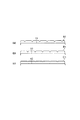
つまり、図5に示す現像容器2の第1、第2のスクリュー5、6の軸部分の横断面図を参照すればよく理解されるように、第1の搬送スクリュー5は現像室3の底部に現像スリーブ8の軸方向に沿ってほぼ平行に配置されており、回転して現像室3内の現像剤Tを軸線方向に沿って一方向に搬送する。又、第2の搬送スクリュー6は攪拌室4内の底部に第1の搬送スクリュー5とほぼ平行に配置され、攪拌室4内の現像剤Tを第1の搬送スクリュー5と反対方向に搬送する。
That is, as can be understood by referring to the cross-sectional view of the shaft portions of the first and
このようにして、第1及び第2の搬送スクリュー5、6の回転による搬送によって、現像剤Tが隔壁7の両端部の開口部である連通部71、72を通じて現像室3と攪拌室4との間で循環される。
In this way, the developer T and the stirring
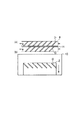
更に、この現像装置1は、現像スリーブ8内のマグネット8aが、現像容器2内で反発磁極を有する、第3の構成を有す。即ち、現像スリーブ8は、非磁性材料で構成され、上記したように、その内部には第1の磁界発生手段であるマグネットローラ8aが非回転状態で設置されているが、このマグネットローラ8は現像極S2と現像剤を搬送する磁極S1、N1、N2、N3を有している。このうち同極である第1磁極N3極と第2磁極N1極は、隣り合って現像容器2内部側に設置されており、極間に反発磁界が形成され、現像剤Tに対してはバリアが形成されており、攪拌室4にて現像剤Tを離すように構成されている。そして、その反発磁極のうち下流側のN1極が層厚規制磁極となる。
Further, the developing
以下に、より具体的な現像剤Tの流れを図6の現像スリーブ8と現像スリーブ11付近の拡大図を用いて説明する。上記に説明したように、現像スリーブ8内の第1磁極N3極と第2磁極N1極間には反発磁界が形成されおり、又、現像スリーブ11の第3磁極S3極と第4磁極S4極間にも反発磁界が形成されている。そして、現像スリーブ8と11の対向部にて、現像スリーブ8の第1磁極N3極と現像スリーブ11の第3磁極S3極は近接している。尚、現像スリーブ8内のN1極とN3極の反発磁界及び現像スリーブ11内のS3極とS4極の反発磁界は同じ側を向き、現像容器2の内部方向を向いている。
Hereinafter, a more specific flow of the developer T will be described with reference to an enlarged view in the vicinity of the developing
このことによって、現像スリーブ8上を搬送され、現像部を通過してきた現像剤Tは、マグネット8aの第1磁極N3極の位置へ至り、下流の第2磁極N1極との反発磁界によって、両スリーブ8と11の対向部である最近接位置をすり抜けて、ほとんどの現像剤Tは矢印eのように通過することができない。
As a result, the developer T that has been transported on the developing
大半の現像剤Tは、現像スリーブ8に連れ回ることができず、矢印fのように現像スリーブ8側のN3極から現像スリーブ11側のマグネット11aの第3磁極S3極方向へのびる磁力線に従って、現像スリーブ11側へ移動し、現像スリーブ11上を攪拌室4内の第2の搬送スクリュー5まで搬送されていく。このサイクルを繰り返していく。
Most of the developer T cannot follow the developing
当然ながら、従来に説明した、第1〜第4の構成を有するので、従来例に示した単一現像スリーブの現像器に比べて、現像効率を高めることができ、潜像により忠実な像を現像することができる。 Of course, since the first to fourth configurations described above are used, the development efficiency can be increased compared to the single developing sleeve developing device shown in the conventional example, and a more faithful image can be obtained. It can be developed.
このような現像装置1においては、従来例に説明したように、複数の現像スリーブを有する構成であっても、反発磁極の一つの磁極を現像剤層厚規制磁極として用いる構成をとった場合、ベタ画像が形成された記録材の搬送方向後端部分にスクリューピッチ状の濃度ムラが発生する虞がある。
In such a developing
この現象は、従来例にも説明したように、反発磁界により剥ぎ取られた後に現像剤層厚規制磁極に移動する、画像履歴のあるトナー濃度の低下した現像剤が、搬送スクリュー5によって直ぐに現像スリーブ8へと搬送されてしまう。そして、スクリューピッチの凹凸状にトナー濃度ムラの状態を持ちながら現像スリーブ11へと搬送、供給される。それが、画像域長手で搬送スクリュー5の回転周期で変わりながら発生していく。そして、第4の、複数の現像スリーブを備える構成を有することで濃度ムラを目立たなくさせるという対策がなされていたが、それでも、ベタ画像においてはスクリューピッチムラが完全に防止されるわけではなかった。
As described in the conventional example, this phenomenon occurs when the developer having a reduced toner concentration having an image history, which moves to the developer layer thickness regulating magnetic pole after being peeled off by the repulsive magnetic field, is immediately developed by the conveying
本実施例のように複数の現像スリーブ8、11を感光ドラム10に近接させ、現像に寄与させた場合のベタ画像におけるスクリューピッチムラについて説明する。
The screw pitch unevenness in the solid image when the plurality of developing
層厚規制極9に混合比率の不安定な現像剤が到来し、感光ドラム10回転方向で上流現像スリーブ8にスクリューピッチ状の濃度ムラDがある状態で現像剤Tが供給される。すると、図6に示す上記の矢印fに従って、現像スリーブ8上下の現像剤が下流現像スリーブ11に移動し、図7(a)に示すように、濃度ムラDの位相は変わるものの下流現像スリーブ11へも、この濃度ムラを有した状態で現像剤が搬送されていく。そのため、図7(b)に示すように、ドラム10上の画像Z上にスクリューピッチ状の濃度ムラDが現れてしまう虞がある。
A developer with an unstable mixing ratio arrives at the layer thickness regulating electrode 9, and the developer T is supplied in the state where there is a screw pitch-like density unevenness D in the upstream developing
特に、高Dutyなベタ画像を連続で流した場合など、急激なトナーの消費を行うため、現像容器2内のトナー濃度がムラになりやすく不安定になり、スクリューピッチ状のムラが生じやすくなる。
In particular, when a high-duty solid image is continuously flowed, the toner is rapidly consumed, so that the toner concentration in the developing
又、上流現像スリーブ8で現像に供され、トナー濃度の下がった現像剤が、僅かではあるが上流現像スリーブ8から下流の現像スリーブ11間の受け渡し磁界と、反発磁界と、に逆らい、つれ回る現像剤が存在してしまう。そして、そのスクリューピッチ状のトナー濃度ムラがある状態で上流現像スリーブ8に現像剤が供給されてしまうこともある。
Further, the developer that has been subjected to the development by the upstream developing
いずれの場合も、上流現像スリーブ8にスクリューピッチ状の濃度ムラをもった画像がドラム10上に現像され、更に、下流現像スリーブ11にも濃度ムラを持った状態で現像剤が搬送されてくる。
In any case, an image having screw pitch-like density unevenness on the upstream developing
ここで、実際に記録材Pに形成される画像は、感光ドラム10表面の第二現像部X2を通過した後の画像、つまり図1で第二現像部X2と転写部23との間の領域Cに形成されている画像である。そして第二現像部X2には、第一現像部X1にて形成された画像上に、現像スリーブ11に担持される現像剤が現像される。つまり、ベタ画像の場合は、感光ドラム10の第一現像部X1と第二現像部X2との間の領域Bに形成されている画像上の現像剤(この場合ベタ画像であるので現像剤層)と、現像スリーブ8から、第一現像部X1にて現像されていない現像剤層が現像スリーブ11との対向部を通じて現像スリーブ11に担持された現像剤層、つまり、図6では矢印fの経路である、図1に示す経路Aに形成されている現像剤層に対する現像動作の影響を受けて形成される画像である。
Here, the image actually formed on the recording material P is the image after passing through the second developing portion X2 on the surface of the
この時、この図1における上記経路A、及び領域B、Cにおける現像剤層のドラム10上や現像スリーブ8上のトナー載り量を光センサなどで検知した濃度の断面プロファイルを測定することができる。以下に、スクリューピッチ状の濃度ムラが発生する状況について、こうして測定された模式的な断面プロファイルの図2、図3を用いて説明する。
At this time, it is possible to measure the cross-sectional profile of the density in which the amount of applied toner on the
スクリューピッチ状の濃度ムラ発生する場合の、上記経路A、及び領域B、Cにおける現像剤層のそれぞれのプロファイルを図3(a)、(b)、(c)に示す。 FIGS. 3A, 3B, and 3C show the profiles of the developer layers in the path A and the regions B and C when the screw pitch-shaped density unevenness occurs.
まず、領域B部分の現像剤層における濃度ムラ、つまり現像スリーブ8で形成された濃度ムラのドラム10軸方向でトナー載り量の断面図を測定すると、濃度が低い部分のトナー量が低く測定され、図3(b)のように、断面ではほぼ等間隔毎にトナーの載りが低くなる部分が生じる。又、上流現像スリーブ8で形成された、同様のスクリューピッチ状の濃度ムラ(トナー載り量ムラ)が保たれたまま、下流側の現像スリーブ11の現像部へ経路Aをたどって運ばれていき、図3(a)に示すように、現像スリーブ8によるドラム10上のトナーの状態(図3(b))と同様な状態となる。
First, when the density unevenness in the developer layer in the region B, that is, the cross-sectional view of the applied toner amount in the axial direction of the
この時、下流現像スリーブ11の現像部X2において、図3(a)に示す経路Aをたどって部分の現像スリーブ8から運ばれたプロファイルA2と、図3(b)に示す第一現像部X1を通過後の領域Bにおける感光ドラム1上のプロファイルB2が重ね合わさる位相となり、感光ドラム1表面が第二現像部X2を通過した後つまり領域Cにおいては、表面のトナーは、図3(c)に示すプロファイルC2のような状態に現像される。
At this time, in the developing portion X2 of the downstream developing
つまり、現像スリーブ8によって感光ドラム10上に現像されたトナーのプロファイルA2と、現像スリーブ8から現像スリーブ11へとその対向部を通じて移動するトナーのプロファイルB2とが、同様の間隔でスクリューピッチムラが生じるため、トナーが低く載る部分同士が重なるようになり、上流側現像スリーブ8によってできた濃度ムラを、下流側の現像スリーブ11で若干、軽微にするものの濃度ムラを消すことはできないと考えることができる。よって、高画質化のために複数本の現像スリーブを配設しても、その性能を活かし切れていない。
That is, the profile of the toner A2 developed on the
そこで、上流及び下流現像スリーブ8、11の周速、ドラム10の周速、又は現像スリーブ8へ現像剤を供給する搬送スクリュー5の角速度等を調整して、第二現像部X2において、現像スリーブ8から現像スリーブ11へと直接移動した経路Aにおける現像剤の現像剤層と現像スリーブ8により現像された感光ドラム1の領域B上のトナー層の両者におけるスクリューピッチムラの凹部分が重ならないようにした。
Accordingly, the peripheral speed of the upstream and downstream developing
この時のドラムの軸方向でのトナー載り量の断面プロファイルを図3と同様に、図2(a)、(b)、(c)に示す。この時の現像スリーブ8から現像スリーブ11に直接移動した経路AにおけるプロファイルA1は、同位置の上記のプロファイルA2と同様であるが、第1現像部X1を通過した後の、つまり領域Bにおける現像スリーブ8によるトナー像の状態においては、この時の下流現像スリーブ11におけるトナー載り量の断面プロファイルB1は図2(b)に示すように、プロファイルA1の凹部と重ならない位置に凹部が発生し、第二現像部X2にて両者が重なっても、凹部同士が重なることがなく、図2(c)に示す領域CにおけるプロファイルC1のように、上流現像スリーブ8で現像された時の断面プロファイルB1には、濃度ムラがあったが、下流現像スリーブ11の現像によって凹んでいる部分にトナーを補い、濃度ムラを大幅に軽減できる。実際に紙上の濃度ムラを測定しても、反射濃度でΔ0.025と面内の濃度均一性が大幅に向上していることが確認できた。
2A, 2B , and 2C show the cross-sectional profiles of the applied toner amount in the axial direction of the drum at this time, as in FIG. The profile A1 in the path A directly moved from the developing
以上より、上流現像スリーブ8で現像し、ドラム1上にできたスクリューピッチ状の濃度ムラが下流現像スリーブ11へ搬送されてきた時の位相と、下流現像スリーブ11上の濃度ムラの位相の重ね合わせによって、最終的なスクリューピッチ状の濃度ムラのレベルが決定されることが分かった。
As described above, the phase when the screw pitch-like density unevenness developed on the
以上に述べたことから、本実施例においては、第二現像部X2にて、第1現像部X1にて形成されたトナー像と下流現像スリーブ11によって現像されるトナー像とのピッチムラの凹部同士が重ならないように条件を定めたことを特徴とする。
As described above, in this embodiment, in the second developing portion X2, the concave portions of the pitch unevenness between the toner image formed in the first developing portion X1 and the toner image developed by the downstream developing
本実施例においては、次の条件を満たすことによって、下流現像スリーブ11側の濃度ムラの位相と上流現像スリーブ8によって現像された感光ドラム10上の濃度ムラの位相との濃淡部分が重なり合わないようにした。
In this embodiment, by satisfying the following condition, the density portion of the density unevenness phase on the downstream developing
まず、現像スリーブ8へ現像剤と供給、攪拌する攪拌スクリュー5の角速度V1とすると、現像スリーブ8上にできるスクリューピッチ状の濃度ムラは2π/V1の間隔で形成される。次に、現像スリーブ8から現像スリーブ11に受け渡されて担持されることによる、それぞれの回転による移動で上流現像スリーブ8の現像部X1から下流現像スリーブ11の現像部X2まで現像剤が搬送される時間、つまり、図1に示す経路Aにおける現像剤層の移動時間をTAとし、感光ドラム1上において、現像剤が第一現像部X1から第二現像部X2まで搬送される時間つまり図1における領域Bを移動する時間をTBとする。当然ながら、TAやTBは、現像スリーブ8、11の周速、現像スリーブ8、11内のマグネットローラ8a、11aの磁力分布と配置や感光ドラム10の周速等によって決まるパラメータである。
First, assuming that the angular velocity V1 of the stirring
ここで、感光ドラム10上の搬送時間TBから現像スリーブ8、11上の搬送時間TAの差分をとり、現像スリーブ8に形成されるスクリューピッチ状の濃度ムラ間隔2π/V1との比率Sをとれば、感光ドラム10と現像スリーブ8、11上の位相のずれがどの位か把握できる。比率Sは式(5)のように表される。
Here, the difference S between the conveyance time TB on the
(|TA−TB|)/(2π/V1)=S (5) (| TA-TB |) / (2π / V1) = S (5)
ここで、実際に、様々な条件下において、比率S(感光ドラム10と現像スリーブ8、11上の位相)をずらしながら記録材27上に形成されたベタ画像のスクリューピッチ状の濃度ムラのレベルを確認していった。その結果を表1に示す。本検討においては、搬送スクリュー5、6としては、図5に示すようなスパイラル状であり、スパイラルの間隔は凡そ15mmの攪拌スクリューを用いた。尚、表1におけるスクリューピッチ状の濃度ムラレベルの評価は、下記のように表現する。
Here, actually, the level of screw pitch density unevenness of the solid image formed on the
××:ムラが大きく目立つ。×:ムラが確認できる。△×:ムラが薄く確認できる。△:ムラが確認できるが目立たない。○:ムラが確認できない。 XX: Unevenness is noticeable. X: Unevenness can be confirmed. Δ: Unevenness can be confirmed. Δ: Unevenness can be confirmed but not noticeable. ○: Unevenness cannot be confirmed.

すると、比率Sが0.25〜0.75であれば面内の濃度差も0.05以下で、スクリューピッチ状の濃度ムラもベタ画像であってもほとんど目立たないレベルまで抑えることが分かった。 Then, it was found that if the ratio S is 0.25 to 0.75, the in-plane density difference is 0.05 or less, and the screw pitch density unevenness is suppressed to a level that is hardly noticeable even in a solid image. .
本検討の現像装置の設定においては、濃度ムラが出る時は、15mm間隔で幅3mm強のスクリューピッチ状の濃度ムラが出た。ここで、比率Sを0.25〜0.75まで許容すると、上流現像スリーブ8で15mm間隔の0mm位置を中心に幅3mmの濃度ムラを形成し、下流現像スリーブ11で約4mm位置を中心に幅3mmの濃度ムラを現像する状況となり、夫々の濃度ムラは重なることはなく、画像上でも目立たないレベルとなる。
In the setting of the developing device of this study, when density unevenness occurred, screw pitch-shaped density unevenness with a width of slightly more than 3 mm appeared at intervals of 15 mm. Here, if the ratio S is allowed from 0.25 to 0.75, the upstream developing
これが、比率Sを0.2以下まで許容するとなると、幅を持つ濃度ムラ同士が重なり合ってしまい、スクリューピッチ状の濃度ムラが見えるようになってしまう。 If this allows the ratio S to be 0.2 or less, density irregularities having widths overlap each other, and screw pitch-shaped density irregularities can be seen.
尚、実際の現像スリーブおよび、感光ドラム10上の濃度ムラ(濃淡パターン)は、上下の現像スリーブ8、11のうち、一方のみに現像バイアスを印加し、片側の現像スリーブでのみ現像を行い、トナー載り量分布(濃淡パターン)の光センサによって観測した。
Note that the density unevenness (light / dark pattern) on the actual developing sleeve and the
又、紙上濃度との対応をとると、感光ドラム10上の軸方向上の載り量に0.03mg/cm2以上の差があり、上下の現像スリーブ8、11によって現像で凹部(淡部)と凹部(淡部)が重なる位相であると、紙上の濃度ムラが0.1以上と目立ってしまう。
Further, when taking the correspondence with the density on the paper, there is a difference of 0.03 mg / cm 2 or more in the axial loading amount on the
しかし、上述の範囲となるように位相をずらせば、感光ドラム10上の軸方向上の載り量が、例え、0.035mg/cm2の差を持っていたとしても、凹部(淡部)を下流現像スリーブ11の凸部(濃部)で重ね合わせれば、記録材27上の濃度差としては、0.04以下になることが検証できている。この紙27上の濃度差が0.04になった時の下流側現像スリーブ11の現像後における感光ドラム10上のトナー載り量の分布(最大載り量―最小載り量)は、約0.01〜0.005mg/cm2であった。
However, if the phase is shifted so as to be in the above-mentioned range, even if the amount of loading in the axial direction on the
従って、感光ドラム10上のトナーの載り量分布(濃淡パターン)を0.01mg/cm2以下に抑えれば、ベタ画像上などで濃度ムラが目立つことはなくなることがわかった。
Therefore, it has been found that if the toner amount distribution (light / dark pattern) on the
又、実験における現像スリーブ8、11上のスクリューピッチ状の濃度ムラの搬送時間、および感光ドラム10上のスクリューピッチ状の濃度ムラの搬送時間は、フォトロン社製の高速カメラ FASTCAM 120KCにオリンパス社製の工業用硬性鏡および、工業用ファイバースコープを組み合わせて測定を行った。
Further, in the experiment, the screw pitch-shaped density unevenness transport time on the developing
以上より、下記の数式(6)を満足するように、現像スリーブ8へ現像剤と供給、攪拌する攪拌スクリュー5の角速度V1と、第一現像部X1から第二現像部X2までの、感光ドラム1上における現像剤の搬送時間TBと、現像スリーブ8、11上における現像剤の搬送時間TAを設定すれば、問題であったスクリューピッチ状の濃度ムラを解消することができる。
From the above, the photosensitive drum from the first developing portion X1 to the second developing portion X2 and the angular velocity V1 of the stirring
N+0.25<(|TA−TB|)/(2π/V1)<N+0.75
(Nは0以上の整数) (6)
N + 0.25 <(| TA−TB |) / (2π / V1) <N + 0.75
(N is an integer greater than or equal to 0) (6)
又、本実施例においては、現像スリーブ内に内包するマグネットの磁力を利用して一方の現像スリーブからもう一方の現像スリーブへと現像剤を受け渡す構成とした。これは、現像剤に対して最小限の負荷で、現像装置内を搬送、攪拌しながら利用することができるので、現像剤の寿命を延命する効果がある。よって、ベタ画像などで濃度ムラのない高品位な画像を長期にわたって提供できるようになる。 In the present embodiment, the developer is transferred from one developing sleeve to the other developing sleeve using the magnetic force of the magnet contained in the developing sleeve. This can be used while transporting and stirring in the developing device with a minimum load on the developer, and thus has the effect of extending the life of the developer. Therefore, it is possible to provide a high-quality image with no density unevenness such as a solid image over a long period of time.
それから、本実施例における現像スリーブ間の受け渡し部におけるマグネット磁極は異極同士(図1の現像スリーブ8のN3と現像スリーブ11のS3)を近接させた構成にしたが、同極同士の構成としても、本発明の効果、作用を同様に得ることができる。又、図1のような受け渡しの構成でなくても、上流側で現像された感光ドラム上の濃度ムラの位相と下流側の現像スリーブ上に形成された濃度ムラの位相の濃淡が重ね合わさらないようにすれば、同様の効果が得ることができる。
Then, the magnetic poles in the transfer portion between the developing sleeves in this embodiment are configured so that the different polarities (N3 of the developing
実施例2
次に、図1に示す本発明の実施例2の現像装置100について説明する。本実施例では、実施例1の効果に加え、更に、現像剤の長寿命化を目指した。
Example 2
Next, the developing
従来例に説明したように、現像剤は、現像剤規制部9にて現像剤同士が摩擦することによって生じるが、この現像剤規制部9での現像剤劣化を防止するために、現像室3における規制ブレード9の配置を調整した。
As described in the conventional example, the developer is generated by the friction between the developers in the developer restricting portion 9. In order to prevent the developer deterioration in the developer restricting portion 9, the developing
即ち、ここでは、現像室3上部に規制ブレード9が配置されているが、この規制ブレード9の位置を、現像スリーブ8の回転方向において、内部のマグネット8aのN1極とN3極である反発極のうちスリーブ8回転方向下流側の第2磁極であるN1極より回転角5°下流側に現像スリーブ8と400μmの間隔を開けて最近接点が位置するように配置した。そして、スリーブ8−ブレード9間距離(SB距離)は、N1極の磁力、スリーブ8上のコート量(本実施例では約30mg/cm2)により最適化するように決定される。
That is, here, the regulating blade 9 is disposed at the upper part of the developing
本実施例での規制ブレード9は、非磁性材料にて作製されたブレードと、その側面に接着された厚み0.3mmの磁性材料にて作製された磁性板とから構成されている。 The regulating blade 9 in this embodiment is composed of a blade made of a nonmagnetic material and a magnetic plate made of a magnetic material having a thickness of 0.3 mm adhered to the side surface thereof.
よって、上記のようにして、現像剤規制部の近傍に反発磁界を形成する一方の磁極を配置する構成にすることによって、現像剤規制部へ溜まる剤溜まり量が少なく、剤に対する負荷が小さいので剤劣化が軽減される。 Therefore, as described above, by arranging one magnetic pole that forms a repulsive magnetic field in the vicinity of the developer restricting portion, the amount of the agent accumulated in the developer restricting portion is small and the load on the agent is small. Agent deterioration is reduced.
更に、前述でも述べたが、現像剤中のキャリアの磁化を小さくすること、即ちキャリアの磁化を小さくすることにより、現像部での、感光ドラム上に現像されたトナー像を摺擦する力が弱くし、高画質化することによっても、現像剤層厚規制部での剤だまりが小さくなり、剤劣化を軽減することができる。 Further, as described above, by reducing the magnetization of the carrier in the developer, that is, by reducing the magnetization of the carrier, the force of rubbing the toner image developed on the photosensitive drum in the developing unit can be increased. weaken, even by particular for high image quality, reservoir agent in the developer layer thickness regulating portion is reduced, it is possible to reduce the dosage degradation.
しかし、低い磁化のキャリアを用いることと上記の磁極配置は、ブレードでの現像剤層厚規制部の剤溜まりが小さくなり、現像スリーブ上へ搬送される現像剤量のむら(現像スリーブ上のコートムラ)を生じやすくなる。又、低磁化のキャリアは、反発磁界では剥ぎ取れない、所謂つれまわる現像剤が多くなり、現像スリーブ上のトナー濃度にムラが発生しやすくなる。そのため、スクリューピッチ状の濃度ムラを発生する虞が高い。 However, the use of a low-magnetization carrier and the above-described magnetic pole arrangement reduce the amount of developer accumulated in the developer layer thickness restricting portion on the blade, and uneven developer amount transported onto the developing sleeve (coating unevenness on the developing sleeve) Is likely to occur. In addition, low-magnetization carriers increase the amount of so-called twisted developer that cannot be peeled off by a repulsive magnetic field, and the toner density on the developing sleeve tends to be uneven. For this reason, there is a high risk of screw-pitch density unevenness.
しかしながら、現像スリーブへ搬送されてくる現像剤量のムラの虞の高い低磁化キャリアを用いることと、上記のような軽負荷の現像器構成を用いることは、現像剤の寿命を延ばすために不可欠である。 However, it is indispensable to use a low-magnetization carrier that has a high possibility of unevenness in the amount of developer conveyed to the developing sleeve and to use a light-load developer configuration as described above in order to extend the life of the developer. It is.
そこで、実施例1と同様に、N+0.25<(|TA−TB|)/(2π/V1)<N+0.75(Nは0以上の整数)となる範囲に、現像スリーブ8へ現像剤と供給、攪拌する攪拌スクリュー5の角速度V1と、現像スリーブ8、11上にて、上流現像スリーブ8の現像部X1から下流側の現像スリーブ11の現像部X2まで現像剤が搬送される時間TAと、感光ドラム10上にて、上流現像スリーブ8の現像部X1から、下流側の現像スリーブ11の現像部X2まで搬送される時間TBを設定すれば、現像剤の長寿命化とスクリューピッチ状の濃度ムラの解消との両立ができる。
Therefore, in the same manner as in the first embodiment, the developer is supplied to the developing
本発明により低磁化キャリアや軽負荷構成の現像装置を使いこなすことによって、スクリューピッチ状の濃度ムラがなく面内の濃度均一性の高い画像を、長期にわたって安定して出力できる。 By making full use of a low-magnetization carrier and a lightly loaded developing device according to the present invention, an image with high density uniformity in a plane without screw pitch density unevenness can be output stably over a long period of time.
又、本発明の現像装置の特徴である、現像容器を現像室と攪拌室に分割する構成は、一般に二成分現像装置に対して実行されているが、現像剤は、二成分現像剤に限定されるわけではなく、トナーを含んでキャリアを含まない一成分現像剤を用いても本発明は適用できる。又、現像装置構成は図1のものに限定されるものではなく、現像剤担持体を複数個有するものであれば、例えば従来例に説明した図8のように攪拌部材を水平配置するものにも適用できる。 In addition, the structure that divides the developing container into the developing chamber and the stirring chamber, which is a feature of the developing device of the present invention, is generally performed for the two-component developing device, but the developer is limited to the two-component developer. However, the present invention can be applied even when a one-component developer containing toner and not containing a carrier is used. Further, the configuration of the developing device is not limited to that shown in FIG. 1. If the developing device has a plurality of developer carriers, for example, the agitating member is arranged horizontally as shown in FIG. Is also applicable.
そして、現像剤担持体の数も、ここでは2つの場合のみについて説明したが、3個以上の時でも、現像容器内に搬送部材を有し、互いに対向する現像剤担持体が2つ以上備えられるものであれば、ベタ画像におけるスクリューピッチムラの問題は、生じる危険性はあり、本発明は適用される。そして、互いに対向する現像剤担持体が3個以上連なる場合は、像担持体の表面移動方向で、最上流の現像剤担持体からそれより下流の現像剤担持体に同様にスクリューピッチムラが移動するので、少なくとも最下流の現像剤担持体において、上流現像剤担持体から移動されてくるスクリューピッチムラの位相を変えるように設定する。 The number of developer carriers is also described here only for two cases. However, even when the number of developer carriers is three or more, the developer container has a conveying member and two or more developer carriers opposite to each other are provided. If it is possible, there is a risk that the problem of unevenness of the screw pitch in the solid image is generated, and the present invention is applied. If there are three or more developer carriers opposite to each other, screw pitch unevenness moves in the same way from the most upstream developer carrier to the downstream developer carrier in the direction of surface movement of the image carrier. Therefore, at least the most downstream developer carrier is set so as to change the phase of the screw pitch unevenness moved from the upstream developer carrier.
そして、本発明は、図10に示されるような、現像室3を重力方向下方に設置し、現像剤担持体8に提供する現像剤の剤圧を下げ、少ない剤量でも現像剤担持体8への現像剤補給が好適にできる構成のものにも適用できる。
In the present invention, as shown in FIG. 10, the developing
そして、本発明は図4に示す構成の画像形成装置にのみ適用されるのではなく、静電記録方式の画像形成装置や単色画像形成装置や、色を更に増やした画像形成装置においても適用でき、中間転写方式の画像形成装置や、又、タンデム方式をとらず、感光ドラムを複数個有さない画像形成装置においても適用できる。 The present invention is not only applied to the image forming apparatus having the configuration shown in FIG. 4, but can also be applied to an electrostatic recording type image forming apparatus, a single-color image forming apparatus, and an image forming apparatus having more colors. The present invention can also be applied to an intermediate transfer type image forming apparatus or an image forming apparatus that does not employ a tandem type and does not have a plurality of photosensitive drums.
以上に説明した画像形成装置の構成部品の寸法、材質、形状、及びその相対位置などは、特に特定的な記載がない限りは、この発明の範囲をそれらのみに限定する趣旨のものではない。 The dimensions, materials, shapes, and relative positions of the components of the image forming apparatus described above are not intended to limit the scope of the present invention only to those unless otherwise specified.
1 現像装置
2 現像容器
5 第1の搬送スクリュー(搬送部材)
6 第2の搬送スクリュー
8 上流現像スリーブ(上流現像剤担持体)
8a マグネットローラ
9 規制ブレード(現像剤規制部材)
10 感光ドラム(像担持体)
11 下流現像スリーブ(下流現像剤担持体)
11a マグネットローラ
DESCRIPTION OF
6 Second conveying
8a Magnet roller 9 Regulating blade (Developer regulating member)
10 Photosensitive drum (image carrier)
11 Downstream development sleeve (downstream developer carrier)
11a Magnet roller
Claims (1)
前記像担持体と対向する第1現像位置へ現像剤を搬送して前記像担持体上に現像剤像を形成する第1現像剤担持体と、
前記第1現像剤担持体から搬送された現像剤を、前記第1現像位置よりも前記像担持体の回転方向下流側の第2現像位置へ搬送して前記像担持体上に現像剤像を形成する第2現像剤担持体と、
前記第1現像剤担持体が収納された収納室に設けられ、前記第1現像剤担持体の回転軸方向に現像剤を搬送して、前記第1現像剤担持体に現像剤を供給する回転自在な搬送スクリューと、
を有し、
前記第1現像剤担持体上の前記第1現像位置にある現像剤を、前記第2現像剤担持体を経由して前記第2現像位置まで移動させるのに要する時間をTAとし、前記像担持体上の現像剤が前記第1現像位置から前記第2現像位置までに移動に要する時間をTBとし、前記搬送スクリューの角速度をV1とし、Nは0以上の整数とする時、数式(1)を満たすことを特徴とする画像形成装置。
N+0.25<(|TA−TB|)/(2π/V1)<N+0.75 (1) An image carrier on which an electrostatic latent image is formed on the surface;
A first developer carrier for transporting a developer to a first development position facing the image carrier to form a developer image on the image carrier;
The developer transported from the first developer carrier is transported to a second development position downstream of the first development position in the rotation direction of the image carrier to form a developer image on the image carrier. A second developer carrier to be formed;
Rotation that is provided in a storage chamber in which the first developer carrier is stored, conveys the developer in the direction of the rotation axis of the first developer carrier, and supplies the developer to the first developer carrier. Flexible conveying screw ,
Have
The time required for moving the developer at the first development position on the first developer carrier to the second development position via the second developer carrier is TA, and the image carrier When the time required for the developer on the body to move from the first development position to the second development position is TB, the angular velocity of the conveying screw is V1, and N is an integer greater than or equal to 0, Formula (1) An image forming apparatus characterized by satisfying the above.
N + 0.25 <(| TA−TB |) / (2π / V1) <N + 0.75 (1)
Priority Applications (2)
| Application Number | Priority Date | Filing Date | Title |
|---|---|---|---|
| JP2004128329A JP4641383B2 (en) | 2004-04-23 | 2004-04-23 | Image forming apparatus |
| US11/107,735 US7236727B2 (en) | 2004-04-23 | 2005-04-18 | Image forming apparatus |
Applications Claiming Priority (1)
| Application Number | Priority Date | Filing Date | Title |
|---|---|---|---|
| JP2004128329A JP4641383B2 (en) | 2004-04-23 | 2004-04-23 | Image forming apparatus |
Publications (3)
| Publication Number | Publication Date |
|---|---|
| JP2005309218A JP2005309218A (en) | 2005-11-04 |
| JP2005309218A5 JP2005309218A5 (en) | 2007-06-07 |
| JP4641383B2 true JP4641383B2 (en) | 2011-03-02 |
Family
ID=35136554
Family Applications (1)
| Application Number | Title | Priority Date | Filing Date |
|---|---|---|---|
| JP2004128329A Expired - Fee Related JP4641383B2 (en) | 2004-04-23 | 2004-04-23 | Image forming apparatus |
Country Status (2)
| Country | Link |
|---|---|
| US (1) | US7236727B2 (en) |
| JP (1) | JP4641383B2 (en) |
Families Citing this family (10)
| Publication number | Priority date | Publication date | Assignee | Title |
|---|---|---|---|---|
| JP4860967B2 (en) * | 2005-09-07 | 2012-01-25 | キヤノン株式会社 | Development device |
| US7725056B2 (en) * | 2006-01-10 | 2010-05-25 | Ricoh Co., Ltd. | Triboelectric charging device and field assisted toner transporter |
| JP4988251B2 (en) * | 2006-06-02 | 2012-08-01 | 株式会社リコー | Developing device and image forming apparatus |
| US7356292B2 (en) * | 2006-06-15 | 2008-04-08 | Xerox Corporation | Electrostatographic developer unit having multiple magnetic brush rolls with a magnetic restrictor for carrier particle emission control |
| JP6039317B2 (en) | 2012-08-31 | 2016-12-07 | キヤノン株式会社 | Image forming apparatus |
| JP6319960B2 (en) * | 2013-07-10 | 2018-05-09 | キヤノン株式会社 | Development device |
| JP2016066057A (en) * | 2014-09-25 | 2016-04-28 | キヤノン株式会社 | Development device |
| JP6402735B2 (en) * | 2016-03-17 | 2018-10-10 | 京セラドキュメントソリューションズ株式会社 | Developing device and image forming apparatus having the same |
| JP6402736B2 (en) * | 2016-03-17 | 2018-10-10 | 京セラドキュメントソリューションズ株式会社 | Developing device and image forming apparatus having the same |
| US10175608B2 (en) * | 2016-03-17 | 2019-01-08 | Kyocera Document Solutions Inc. | Developing device and image forming apparatus provided with same |
Citations (6)
| Publication number | Priority date | Publication date | Assignee | Title |
|---|---|---|---|---|
| JPS58134654A (en) * | 1982-02-05 | 1983-08-10 | Minolta Camera Co Ltd | Developing method of electrostatic latent image |
| JPH06161237A (en) * | 1992-06-11 | 1994-06-07 | Canon Inc | Image forming device |
| JPH09281791A (en) * | 1996-04-11 | 1997-10-31 | Fujitsu Ltd | Developing device |
| JP2002023471A (en) * | 2000-07-07 | 2002-01-23 | Hitachi Koki Co Ltd | Image forming device |
| JP2003195638A (en) * | 2001-12-27 | 2003-07-09 | Canon Inc | Developing device and image forming apparatus provided with it |
| JP2003323043A (en) * | 2002-04-26 | 2003-11-14 | Canon Inc | Developing device and image forming apparatus |
Family Cites Families (3)
| Publication number | Priority date | Publication date | Assignee | Title |
|---|---|---|---|---|
| US6067433A (en) | 1997-07-04 | 2000-05-23 | Canon Kabushiki Kaisha | Developing apparatus for regulating the amount of developer in the vicinity of repulsive magnetic pole |
| JP3382541B2 (en) | 1997-07-04 | 2003-03-04 | キヤノン株式会社 | Developing device |
| US6993274B2 (en) * | 2002-11-14 | 2006-01-31 | Canon Kabushiki Kaisha | Developing apparatus with plural developer bearing members for each image bearing member |
-
2004
- 2004-04-23 JP JP2004128329A patent/JP4641383B2/en not_active Expired - Fee Related
-
2005
- 2005-04-18 US US11/107,735 patent/US7236727B2/en active Active
Patent Citations (6)
| Publication number | Priority date | Publication date | Assignee | Title |
|---|---|---|---|---|
| JPS58134654A (en) * | 1982-02-05 | 1983-08-10 | Minolta Camera Co Ltd | Developing method of electrostatic latent image |
| JPH06161237A (en) * | 1992-06-11 | 1994-06-07 | Canon Inc | Image forming device |
| JPH09281791A (en) * | 1996-04-11 | 1997-10-31 | Fujitsu Ltd | Developing device |
| JP2002023471A (en) * | 2000-07-07 | 2002-01-23 | Hitachi Koki Co Ltd | Image forming device |
| JP2003195638A (en) * | 2001-12-27 | 2003-07-09 | Canon Inc | Developing device and image forming apparatus provided with it |
| JP2003323043A (en) * | 2002-04-26 | 2003-11-14 | Canon Inc | Developing device and image forming apparatus |
Also Published As
| Publication number | Publication date |
|---|---|
| US20050238390A1 (en) | 2005-10-27 |
| US7236727B2 (en) | 2007-06-26 |
| JP2005309218A (en) | 2005-11-04 |
Similar Documents
| Publication | Publication Date | Title |
|---|---|---|
| JP5970444B2 (en) | Developing device and image forming apparatus having the same | |
| JP4136481B2 (en) | Developing device and image forming apparatus | |
| JP6183695B2 (en) | DEVELOPING DEVICE, IMAGE FORMING DEVICE EQUIPPED WITH THE SAME | |
| US7236727B2 (en) | Image forming apparatus | |
| JP6447532B2 (en) | Developing device and image forming apparatus including the same | |
| JP6330688B2 (en) | Developing device and image forming apparatus including the same | |
| JP4167002B2 (en) | Developing device and image forming apparatus | |
| JP2012155144A (en) | Developing device and image forming apparatus including the same | |
| JP2017053949A (en) | Developing device and image forming apparatus including the same | |
| JP3950735B2 (en) | Developing device and image forming apparatus | |
| JP5439409B2 (en) | Developing device and image forming apparatus including the same | |
| JP2003167480A (en) | Developing device and image forming apparatus equipped therewith | |
| JP3840139B2 (en) | Developing device and image forming apparatus | |
| JP6589829B2 (en) | Agitating and conveying member, developing device including the same, and image forming apparatus | |
| JP5054333B2 (en) | Developing device, process cartridge, and image forming apparatus | |
| JP2017194645A (en) | Developing device | |
| JP5610920B2 (en) | Developing device and image forming apparatus | |
| JP2007322570A (en) | Developing roller, developing device, process cartridge and image forming apparatus | |
| JP2003122126A (en) | Developing device and image forming device | |
| JP7416274B2 (en) | Developing device and image forming device equipped with the same | |
| US20160370729A1 (en) | Developing device and image forming apparatus | |
| JP2009109966A (en) | Developer transport device, developing device and image forming apparatus | |
| JP2009288581A (en) | Developing device and image forming apparatus equipped with the same | |
| JP2005215460A (en) | Developing device | |
| JP2001034066A (en) | Image forming device and developing device |
Legal Events
| Date | Code | Title | Description |
|---|---|---|---|
| A521 | Written amendment |
Free format text: JAPANESE INTERMEDIATE CODE: A523 Effective date: 20070416 |
|
| A621 | Written request for application examination |
Free format text: JAPANESE INTERMEDIATE CODE: A621 Effective date: 20070416 |
|
| A977 | Report on retrieval |
Free format text: JAPANESE INTERMEDIATE CODE: A971007 Effective date: 20091224 |
|
| A131 | Notification of reasons for refusal |
Free format text: JAPANESE INTERMEDIATE CODE: A131 Effective date: 20100105 |
|
| A521 | Written amendment |
Free format text: JAPANESE INTERMEDIATE CODE: A523 Effective date: 20100308 |
|
| A02 | Decision of refusal |
Free format text: JAPANESE INTERMEDIATE CODE: A02 Effective date: 20100511 |
|
| A521 | Written amendment |
Free format text: JAPANESE INTERMEDIATE CODE: A523 Effective date: 20100806 |
|
| A911 | Transfer to examiner for re-examination before appeal (zenchi) |
Free format text: JAPANESE INTERMEDIATE CODE: A911 Effective date: 20100916 |
|
| TRDD | Decision of grant or rejection written | ||
| A01 | Written decision to grant a patent or to grant a registration (utility model) |
Free format text: JAPANESE INTERMEDIATE CODE: A01 Effective date: 20101124 |
|
| A01 | Written decision to grant a patent or to grant a registration (utility model) |
Free format text: JAPANESE INTERMEDIATE CODE: A01 |
|
| A61 | First payment of annual fees (during grant procedure) |
Free format text: JAPANESE INTERMEDIATE CODE: A61 Effective date: 20101129 |
|
| R150 | Certificate of patent or registration of utility model |
Free format text: JAPANESE INTERMEDIATE CODE: R150 Ref document number: 4641383 Country of ref document: JP Free format text: JAPANESE INTERMEDIATE CODE: R150 |
|
| FPAY | Renewal fee payment (event date is renewal date of database) |
Free format text: PAYMENT UNTIL: 20131210 Year of fee payment: 3 |
|
| LAPS | Cancellation because of no payment of annual fees |