JP2017194645A - Developing device - Google Patents
Developing device Download PDFInfo
- Publication number
- JP2017194645A JP2017194645A JP2016086443A JP2016086443A JP2017194645A JP 2017194645 A JP2017194645 A JP 2017194645A JP 2016086443 A JP2016086443 A JP 2016086443A JP 2016086443 A JP2016086443 A JP 2016086443A JP 2017194645 A JP2017194645 A JP 2017194645A
- Authority
- JP
- Japan
- Prior art keywords
- developer
- chamber
- developing
- communication port
- screw
- Prior art date
- Legal status (The legal status is an assumption and is not a legal conclusion. Google has not performed a legal analysis and makes no representation as to the accuracy of the status listed.)
- Granted
Links
- 238000004891 communication Methods 0.000 claims abstract description 64
- 238000005192 partition Methods 0.000 claims abstract description 22
- 230000032258 transport Effects 0.000 claims description 12
- 238000011144 upstream manufacturing Methods 0.000 claims description 11
- 238000007599 discharging Methods 0.000 claims description 5
- 230000007547 defect Effects 0.000 abstract description 11
- 230000035515 penetration Effects 0.000 abstract 1
- 238000003756 stirring Methods 0.000 description 73
- 239000000463 material Substances 0.000 description 12
- 238000004140 cleaning Methods 0.000 description 6
- 230000001105 regulatory effect Effects 0.000 description 6
- 238000000926 separation method Methods 0.000 description 6
- 239000011248 coating agent Substances 0.000 description 4
- 238000000576 coating method Methods 0.000 description 4
- 239000010410 layer Substances 0.000 description 4
- 238000000034 method Methods 0.000 description 4
- 238000013019 agitation Methods 0.000 description 3
- 230000015572 biosynthetic process Effects 0.000 description 3
- 238000010586 diagram Methods 0.000 description 3
- 239000011347 resin Substances 0.000 description 3
- 229920005989 resin Polymers 0.000 description 3
- 239000003795 chemical substances by application Substances 0.000 description 2
- 239000003086 colorant Substances 0.000 description 2
- 230000007423 decrease Effects 0.000 description 2
- 239000002245 particle Substances 0.000 description 2
- 238000005086 pumping Methods 0.000 description 2
- 229910000838 Al alloy Inorganic materials 0.000 description 1
- XAGFODPZIPBFFR-UHFFFAOYSA-N aluminium Chemical compound [Al] XAGFODPZIPBFFR-UHFFFAOYSA-N 0.000 description 1
- 229910052782 aluminium Inorganic materials 0.000 description 1
- 239000002131 composite material Substances 0.000 description 1
- 230000002950 deficient Effects 0.000 description 1
- 238000005516 engineering process Methods 0.000 description 1
- 239000007788 liquid Substances 0.000 description 1
- 239000006247 magnetic powder Substances 0.000 description 1
- 239000000155 melt Substances 0.000 description 1
- 230000002093 peripheral effect Effects 0.000 description 1
- 229920000728 polyester Polymers 0.000 description 1
- 230000000379 polymerizing effect Effects 0.000 description 1
- 238000003825 pressing Methods 0.000 description 1
- 238000010298 pulverizing process Methods 0.000 description 1
- 238000010008 shearing Methods 0.000 description 1
- 229920001909 styrene-acrylic polymer Polymers 0.000 description 1
- 239000002344 surface layer Substances 0.000 description 1
- 229910000859 α-Fe Inorganic materials 0.000 description 1
Images

Classifications
-
- G—PHYSICS
- G03—PHOTOGRAPHY; CINEMATOGRAPHY; ANALOGOUS TECHNIQUES USING WAVES OTHER THAN OPTICAL WAVES; ELECTROGRAPHY; HOLOGRAPHY
- G03G—ELECTROGRAPHY; ELECTROPHOTOGRAPHY; MAGNETOGRAPHY
- G03G15/00—Apparatus for electrographic processes using a charge pattern
- G03G15/06—Apparatus for electrographic processes using a charge pattern for developing
- G03G15/08—Apparatus for electrographic processes using a charge pattern for developing using a solid developer, e.g. powder developer
- G03G15/0822—Arrangements for preparing, mixing, supplying or dispensing developer
- G03G15/0887—Arrangements for conveying and conditioning developer in the developing unit, e.g. agitating, removing impurities or humidity
- G03G15/0891—Arrangements for conveying and conditioning developer in the developing unit, e.g. agitating, removing impurities or humidity for conveying or circulating developer, e.g. augers
- G03G15/0893—Arrangements for conveying and conditioning developer in the developing unit, e.g. agitating, removing impurities or humidity for conveying or circulating developer, e.g. augers in a closed loop within the sump of the developing device
Landscapes
- Physics & Mathematics (AREA)
- General Physics & Mathematics (AREA)
- Dry Development In Electrophotography (AREA)
- Magnetic Brush Developing In Electrophotography (AREA)
Abstract
Description
本発明は、プリンタ、複写機、ファクシミリあるいは複合機などの電子写真技術を用いた画像形成装置に好適な現像装置に関する。 The present invention relates to a developing device suitable for an image forming apparatus using electrophotographic technology such as a printer, a copying machine, a facsimile machine, or a multifunction machine.
プリンタ、複写機、ファクシミリあるいは複合機などの画像形成装置は、感光ドラム上に形成した静電潜像を現像剤により現像して、可視像化する現像装置を備えている。現像装置では、非磁性トナーと磁性キャリアからなる二成分現像剤(以下、単に現像剤と呼ぶ)が用いられている。現像装置として、現像スリーブに現像剤を供給する現像室と、現像スリーブより剥離された現像剤を回収する撹拌室とを備え、現像室と撹拌室とで現像剤を循環させる、所謂、機能分離型の構成が知られている(特許文献1、特許文献2)。現像室と撹拌室は互いに連通口によって連通されており、各室内には現像剤を搬送する現像スクリュー、撹拌スクリューがそれぞれ配設されている。
2. Description of the Related Art Image forming apparatuses such as printers, copiers, facsimile machines, and multifunction machines include a developing device that develops an electrostatic latent image formed on a photosensitive drum with a developer to make a visible image. In the developing device, a two-component developer (hereinafter simply referred to as a developer) composed of a non-magnetic toner and a magnetic carrier is used. The developing device includes a developing chamber for supplying a developer to the developing sleeve and a stirring chamber for collecting the developer separated from the developing sleeve, and the developer is circulated between the developing chamber and the stirring chamber, so-called function separation. The structure of the mold is known (
機能分離型の現像装置の場合、現像剤が安定した状態(所謂、定常状態)に至ると、撹拌室では、現像剤の剤面高さが撹拌スクリューの現像剤搬送方向上流から下流へ向けて徐々に高くなる。そして、現像剤は撹拌スクリューの現像剤搬送方向下流側の連通口を通って撹拌室から現像室へと受け渡される。なお、以下の説明において、特に断りなく上流又は下流といった場合、撹拌スクリューの現像剤搬送方向上流又は現像剤搬送方向下流を指す。 In the case of a function separation type developing device, when the developer reaches a stable state (so-called steady state), in the stirring chamber, the height of the developer surface increases from upstream to downstream in the developer conveying direction of the stirring screw. Gradually higher. The developer is transferred from the stirring chamber to the developing chamber through a communication port on the downstream side in the developer conveying direction of the stirring screw. In the following description, the term “upstream” or “downstream” refers to the developer conveying direction upstream of the stirring screw or the developer conveying direction downstream without particular notice.
また、画像形成に応じてキャリアが劣化し帯電性能が低下するので、新しい現像剤を補給すると共に余分な現像剤を排出口から排出する、所謂キャリアリフレッシュ方式(ACR方式)の装置も知られている(特許文献3)。キャリアリフレッシュ方式の現像装置の一例として、撹拌スクリューの下流に、撹拌スクリューと反対方向に現像剤を搬送する返しスクリューが配置され、さらにその下流に排出口が形成されている装置がある。この装置の場合、撹拌スクリューに搬送される現像剤のうち返しスクリューの搬送力に逆らって下流側に移動した現像剤が排出口から排出される。 In addition, since the carrier deteriorates and the charging performance is lowered in accordance with image formation, a so-called carrier refresh method (ACR method) apparatus that replenishes new developer and discharges excess developer from the discharge port is also known. (Patent Document 3). As an example of the carrier refresh type developing device, there is a device in which a return screw that conveys the developer in a direction opposite to the stirring screw is disposed downstream of the stirring screw, and a discharge port is formed downstream thereof. In the case of this apparatus, of the developer conveyed to the stirring screw, the developer that has moved downstream against the conveying force of the return screw is discharged from the discharge port.
上述の現像装置では、現像剤の流動性が低くなると撹拌室から現像室への現像剤の受け渡しが抑制され、撹拌室内で現像剤の剤面が高くなりやすい。撹拌室内で現像剤の剤面が高くなると、現像剤が現像スリーブの表面に接触した状態になり、現像スリーブに連れ回されやすくなる。また、現像剤が現像スリーブより剥離され難くなり、剥離されなかった現像剤が現像スリーブに連れ回される。こうして現像スリーブに連れ回される現像剤は、現像室から供給される現像剤とともに現像に供される。しかし、現像スリーブに連れ回される現像剤は現像室から供給される現像剤に比べてトナー濃度が低く、現像に供されると濃度ムラのような画像不良を生じさせ得る。 In the above-described developing device, when the flowability of the developer is lowered, delivery of the developer from the stirring chamber to the developing chamber is suppressed, and the developer surface of the developer tends to be high in the stirring chamber. When the developer surface becomes high in the agitation chamber, the developer comes into contact with the surface of the developing sleeve and is easily rotated along with the developing sleeve. Further, it becomes difficult for the developer to be peeled off from the developing sleeve, and the developer that has not been peeled off is rotated around the developing sleeve. The developer thus rotated along the developing sleeve is used for development together with the developer supplied from the developing chamber. However, the developer rotated by the developing sleeve has a lower toner concentration than the developer supplied from the developing chamber, and when used for development, it may cause image defects such as density unevenness.
例え現像剤の流動性が低くなっても撹拌室から現像室への現像剤の受け渡しを抑制させないためには、下流側の連通口を撹拌スクリューに沿って下流側に幅広くすることが考えられる。ただし、単に連通口を下流側に幅広くすると、連通口が返しスクリューにまでかかってしまい現像剤のほとんどが現像室に受け渡されることから、現像剤の排出が抑制され得る。かといって、連通口を幅広くするために返しスクリューをも下流側に移動させるとなると、現像容器ひいては現像装置を大型化するしかなく、これは最近の装置の小型化の要望に反する。そこで、現像剤の排出を抑制することなく、撹拌室から現像室への現像剤の受け渡しを行い得る装置が従来から望まれていたが、未だそうした装置は提案されていない。 For example, in order not to suppress the delivery of the developer from the stirring chamber to the developing chamber even if the flowability of the developer is lowered, it is conceivable that the downstream communication port is widened downstream along the stirring screw. However, if the communication port is simply widened to the downstream side, the communication port extends back to the screw and most of the developer is transferred to the developing chamber, so that the discharge of the developer can be suppressed. However, if the return screw is also moved downstream in order to widen the communication port, the development container and thus the development apparatus must be enlarged, which is contrary to the recent demand for downsizing of the apparatus. Thus, an apparatus that can deliver the developer from the stirring chamber to the developing chamber without suppressing the discharge of the developer has been conventionally desired, but such an apparatus has not yet been proposed.
本発明は上記問題に鑑みてなされたもので、機能分離型の構成で、撹拌室から現像室への現像剤の受け渡しを適切に且つ排出口からの現像剤の排出を抑制することなしに行い得る現像装置の提供を目的とする。 The present invention has been made in view of the above problems, and has a function-separated configuration and appropriately transfers the developer from the stirring chamber to the developing chamber without suppressing the discharge of the developer from the discharge port. It is an object of the present invention to provide a developing device.
本発明に係る現像装置は、現像剤を担持して回転する現像剤担持体と、前記現像剤担持体に現像剤を供給する第一室と、前記第一室とで現像剤の循環経路を形成すると共に前記現像剤担持体から現像剤を回収する第二室と、前記第二室に形成され現像剤を排出する排出口とを有する現像容器と、前記第一室に配設され、第一方向に現像剤を搬送する第一搬送スクリューと、水平方向から視て前記第一搬送スクリューと少なくとも一部が重なるように前記第二室に配設され、前記第一方向と反対の第二方向に現像剤を搬送する第一搬送部と、前記第一搬送部の前記第二方向下流側で前記第一搬送部と前記排出口との間に配置され、前記第一方向に現像剤を搬送する返し部とを有する第二搬送スクリューと、前記現像容器内で前記第一室と前記第二室とを隔て、前記第二方向下流側に前記第二室から前記第一室に現像剤を受け渡す第一連通口と、前記第二方向上流側に前記第一室から前記第二室に現像剤を受け渡す第二連通口と、水平方向から視て少なくとも前記返し部の一部に対向する位置に配置され、下端が前記第一連通口の下端よりも上方に形成された第三連通口とを有する隔壁と、を備える、ことを特徴とする。 In the developing device according to the present invention, a developer carrying body that rotates while carrying a developer, a first chamber that supplies the developer to the developer carrying body, and a circulation path of the developer between the first chamber A developer container having a second chamber for forming and collecting the developer from the developer carrying member; a discharge port formed in the second chamber for discharging the developer; and disposed in the first chamber, A first conveying screw that conveys the developer in one direction, and a second opposite to the first direction, disposed in the second chamber so as to at least partially overlap the first conveying screw when viewed from the horizontal direction. A first conveying unit that conveys the developer in the direction, and the downstream of the first conveying unit in the second direction between the first conveying unit and the discharge port, and the developer in the first direction A second conveying screw having a return portion to convey, the first chamber and the first chamber in the developing container; A first passage through which the developer is transferred from the second chamber to the first chamber on the downstream side in the second direction, and the second chamber on the upstream side in the second direction. A second communication port for delivering the developer to the first position and a position facing at least a part of the return portion when viewed from the horizontal direction, and a lower end formed above the lower end of the first communication port. And a partition wall having a three-way opening.
本発明に係る現像装置は、現像剤を担持して回転する現像剤担持体と、前記現像剤担持体に現像剤を供給する第一室と、前記第一室とで現像剤の循環経路を形成すると共に前記現像剤担持体から現像剤を回収する第二室と、前記第二室に形成され現像剤を排出する排出口とを有する現像容器と、前記第一室に配設され、第一方向に現像剤を搬送する第一搬送スクリューと、水平方向から視て前記第一搬送スクリューと少なくとも一部が重なるように前記第二室に配設され、前記第一方向と反対の第二方向に現像剤を搬送する第一搬送部と、前記第一搬送部の前記第二方向下流側で前記第一搬送部と前記排出口との間に配置され、前記第一方向に現像剤を搬送する返し部とを有する第二搬送スクリューと、前記現像容器内で前記第一室と前記第二室とを隔て、前記第二方向下流側に前記第二室から前記第一室に現像剤を受け渡す第一連通口と、前記第二方向上流側に前記第一室から前記第二室に現像剤を受け渡す第二連通口とを有する隔壁と、を備え、前記第一連通口は、水平方向から視て前記第一搬送部の前記第二方向下流側の一部と前記返し部の一部とに対向するように形成されている、ことを特徴とする。 In the developing device according to the present invention, a developer carrying body that rotates while carrying a developer, a first chamber that supplies the developer to the developer carrying body, and a circulation path of the developer between the first chamber A developer container having a second chamber for forming and collecting the developer from the developer carrying member; a discharge port formed in the second chamber for discharging the developer; and disposed in the first chamber, A first conveying screw that conveys the developer in one direction, and a second opposite to the first direction, disposed in the second chamber so as to at least partially overlap the first conveying screw when viewed from the horizontal direction. A first conveying unit that conveys the developer in the direction, and the downstream of the first conveying unit in the second direction between the first conveying unit and the discharge port, and the developer in the first direction A second conveying screw having a return portion to convey, the first chamber and the first chamber in the developing container; A first passage through which the developer is transferred from the second chamber to the first chamber on the downstream side in the second direction, and the second chamber on the upstream side in the second direction. A partition wall having a second communication port for delivering the developer to the first serial port, and a part of the first conveying portion on the downstream side in the second direction as viewed from the horizontal direction and the return. It is formed so that it may oppose a part of part.
本発明によれば、機能分離型の構成で、排出口からの現像剤の排出を抑制することなく、撹拌室から現像室への現像剤の受け渡しが適切に行われることから、もって現像剤の受け渡しや現像剤の排出に起因する画像不良の発生を低減することができる。 According to the present invention, since the developer is appropriately transferred from the stirring chamber to the developing chamber without suppressing the discharging of the developer from the discharge port in the function separation type configuration, It is possible to reduce the occurrence of image defects due to delivery or developer discharge.
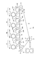
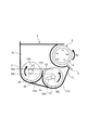
まず、本実施形態の現像装置を適用した画像形成装置の構成について図1を用いて説明する。図1に示す画像形成装置100は、中間転写ベルト25に沿って画像形成部PY、PM、PC、PKを配列したタンデム型の中間転写方式のフルカラープリンタである。
First, the configuration of an image forming apparatus to which the developing device of this embodiment is applied will be described with reference to FIG. An
<画像形成装置>
画像形成部PYでは、感光ドラム10Yにイエロートナー像が形成されて中間転写ベルト25に転写される。画像形成部PMでは、感光ドラム10Mにマゼンタトナー像が形成されて中間転写ベルト25に転写される。画像形成部PC、PKでは、それぞれ感光ドラム10C、10Kにシアントナー像、ブラックトナー像が形成されて中間転写ベルト25に転写される。中間転写ベルト25に転写された四色のトナー像は、二次転写部(二次転写ニップ部)T2へ搬送されて記録材S(用紙、OHPシートなどのシート材など)へ一括二次転写される。記録材Sは、不図示の給紙カセットから1枚ずつ取り出されて二次転写部T2へ搬送される。
<Image forming apparatus>
In the image forming unit PY, a yellow toner image is formed on the
画像形成部PY、PM、PC、PKは、現像装置1Y、1M、1C、1Kで用いるトナーの色がイエロー、マゼンタ、シアン、ブラックと異なる以外は、ほぼ同一に構成される。以下では、画像形成部PY、PM、PC、PKの区別を表す符号末尾のY、M、C、Kを省略して、画像形成部PY〜PKの構成及び動作を説明する。
The image forming units PY, PM, PC, and PK are configured substantially the same except that the colors of toner used in the developing
画像形成部Pには、像担持体としての感光ドラム10を囲んで、帯電ローラ21、露光装置22、現像装置1、転写ローラ23、ドラムクリーニング装置24が配置されている。感光ドラム10はアルミニウム製シリンダの外周面に感光層が形成されたもので、所定のプロセススピードで図1の矢印R1方向に回転される。
In the image forming portion P, a charging roller 21, an exposure device 22, a developing
帯電ローラ21は帯電電圧が印加されて感光ドラム10に接触することで、感光ドラム10を一様な負極性の暗部電位に帯電させる。露光装置22は、各色の分解色画像を展開した走査線画像データをON−OFF変調したレーザービームをレーザー発光素子から発生し、これを回転ミラーで走査して帯電させた感光ドラム10の表面に画像の静電像を書き込む。現像装置1は、トナーを感光ドラム10に供給して静電像をトナー像に現像する。現像装置1については詳細を後述する(図2乃至図6参照)。
The charging roller 21 is charged with a charging voltage and contacts the
転写ローラ23は、中間転写ベルト25を挟んで感光ドラム10に対向配置され、感光ドラム10と中間転写ベルト25との間にトナー像の一次転写部(一次転写ニップ部)T1を形成する。一次転写部T1では、例えば高圧電源(不図示)により転写ローラ23に一次転写電圧が印加されることで、トナー像が感光ドラム10から中間転写ベルト25へ一次転写される。即ち、転写ローラ23に対しトナーの帯電極性と逆極性の一次転写電圧が印加されると、感光ドラム10上のトナー像が中間転写ベルト25に静電吸引されて転写が行われる。ドラムクリーニング装置24は、感光ドラム10にクリーニングブレードを摺擦させて、一次転写後に感光ドラム10上に僅かに残る一次転写残トナーを除去する。
The transfer roller 23 is disposed opposite to the
中間転写ベルト25は、テンションローラ26、二次転写内ローラ27及び駆動ローラ28等のローラに掛け渡して支持され、駆動ローラ28に駆動されて図1の矢印R2方向に回転される。二次転写部T2は、二次転写外ローラ29に支持された中間転写ベルト25に二次転写内ローラ27を当接して形成される記録材Sへのトナー像転写ニップ部である。二次転写部T2では、二次転写内ローラ27に所定の二次転写電圧が印加されることで、トナー像が中間転写ベルト25から二次転写部T2に挟持搬送される記録材Sへ二次転写される。二次転写後に中間転写ベルト25に付着したまま残る二次転写残トナーは、ベルトクリーニング装置30が中間転写ベルト25を摺擦することにより除去される。ベルトクリーニング装置30は、中間転写ベルト25にクリーニングブレードを摺擦させて二次転写残トナーを除去する。
The
二次転写部T2で四色のトナー像を二次転写された記録材Sは、定着装置31へ搬送される。定着装置31は、不図示の対向するローラもしくはベルト等による圧力と、一般的にはヒータ等の熱源(不図示)による熱を加えて記録材S上にトナー像を溶融固着する。定着装置31によりトナー像が定着された記録材Sは、機体外へ排出される。
The recording material S on which the four-color toner images are secondarily transferred by the secondary transfer portion T2 is conveyed to the fixing
トナー補給装置32は、画像形成に伴い現像装置1のトナーが消費されることに応じて、消費されたトナー量に相当する分のトナー(詳しくは補給剤)を現像装置1に補給可能である。
The toner replenishing device 32 can replenish the developing
<現像装置>
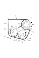
本実施形態の現像装置1について、図2乃至図6を用いて説明する。現像装置1は、図2に示すように、ハウジングを形成する現像容器2、現像剤担持体としての現像スリーブ3、規制ブレード5、第一搬送スクリューとしての現像スクリュー13、第二搬送スクリューとしての撹拌スクリュー14などを備える。
<Developing device>
The developing
現像容器2には、非磁性トナーと磁性キャリアとを含む二成分現像剤が収容されている。つまり、本実施形態では現像方式として二成分現像方式を用い、マイナス帯電極性の非磁性トナーとプラス帯電極性の磁性キャリアを混合して現像剤として用いる。非磁性トナーはポリエステル、スチレンアクリル等の樹脂に着色料、ワックス成分などを内包し、粉砕あるいは重合によって粉体としたものである。磁性キャリアは、フェライト粒子や磁性粉を混錬した樹脂粒子からなるコアの表層に樹脂コートを施したものである。初期状態の現像剤中のトナー濃度(現像剤の全重量に占めるトナーの重量の割合(比率)、TD比とも呼ぶ)は、本実施形態では例えば8%である。
The developing
現像容器2は、感光ドラム10(図1参照)に対向した一部分が開口しており、この開口部に一部が露出するようにして現像剤担持体としての現像スリーブ3が回転可能に配置されている。現像スリーブ3は、アルミニウム合金などの非磁性材料で円筒状に形成され、図2の矢印R3方向に回転駆動される。現像スリーブ3の内側には、複数の磁極により構成されるマグネットローラ4が回転不能に配置されている。
A part of the developing
現像スリーブ3は図2の矢印R3方向に回転し、マグネットローラ4の汲み上げ磁極N1極の位置で吸着した現像剤を規制ブレード5方向へ担持搬送する。規制磁極S1極によって穂立ちした現像剤は、現像スリーブ3と規制ブレード5のギャップを通過する際に規制ブレード5によってせん断力を受けてその量が規制され、現像スリーブ3上に所定の層厚の現像剤層が形成される。形成された現像剤層は感光ドラム10と対向する現像領域に担持搬送され、現像磁極N2極によって磁気穂を形成した状態で感光ドラム10の表面に形成されている静電潜像を現像する。現像に供された後の現像剤は、剥ぎ取り磁極N3極と汲み上げ磁極N1極の間で同極が隣り合うことで形成される無磁力帯によって現像スリーブ3より剥離される。
The developing
<現像容器>
現像容器2は、第一室としての現像室11と第二室としての撹拌室12とが形成され、現像室11と撹拌室12との間に、現像室11と撹拌室12とを区画する隔壁15が設けられている。隔壁15は、現像容器2内(現像容器内)に底面部2cから突出するようにして現像室11と撹拌室12とを隔てている。また、隔壁15は現像スリーブ3の回転軸線方向に延在しており、現像室11及び撹拌室12は現像スリーブ3の回転軸線方向に沿って形成されている。そして、本実施形態では、撹拌室12側の底面部12aが現像室11側の底面部11aよりも上方となるように、水平方向から視て現像室11と撹拌室12とが高低差を有して配置されている。
<Development container>
In the developing
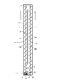
隔壁15は、図3に示すように、長手方向両端側にそれぞれ現像室11と撹拌室12とを連通させる第一連通口16と第二連通口17とを有する。第一連通口16は撹拌室12から現像室11へ現像剤の受け渡しを可能とし、第二連通口17は現像室11から撹拌室12へ現像剤の受け渡しを可能とする現像剤の受け渡し部である。撹拌スクリュー14の回転軸線方向(長手方向)の長さに関し、第一連通口16及び第二連通口17は共に30mmに形成される。また、隔壁15は第一連通口16と第二連通口17の他に第三連通口18を有している。第三連通口18は、第一連通口16と同様に撹拌室12から現像室11へ現像剤の受け渡し可能に形成されている。第三連通口18については後述する(図4参照)。隔壁15の上部には、図2に示すように、現像スリーブ3に近接するように延設され、現像スリーブ3より剥離された現像剤を撹拌室12に案内するための案内部材151が設けられている。案内部材151は、現像スリーブ3の現像剤を担持可能なコート領域を少なくとも含む範囲に亘り設けられるのが好ましい。
As shown in FIG. 3, the
図3に示すように、現像室11には、現像室11で所定の第一方向に現像剤を搬送する現像スクリュー13が配設されている。撹拌室12には、撹拌室12で現像スクリュー13と反対の第二方向に現像剤を搬送する第一搬送部141を有する撹拌スクリュー14が配設されている。現像スクリュー13及び撹拌スクリュー14は、それぞれ回転軸13a,14aの周囲に羽根13b,14bを螺旋状に形成することで構成される。回転軸13a,14aの両端部は、それぞれ現像容器2に回転自在に支持されている。現像スクリュー13と撹拌スクリュー14は、水平方向から視て少なくとも一部が重なるように配置されている。本実施形態では、図2に示すように、撹拌スクリュー14の下端14cが水平方向から視て現像スクリュー13の下端13cよりも上方になるように配置されている。これら現像スクリュー13と撹拌スクリュー14とは、例えば回転軸13a,14aの軸径が6mm、羽根13b,14bの直径が18mm、スクリューピッチが40mmに形成されている。
As shown in FIG. 3, the developing
現像スリーブ3、現像スクリュー13、撹拌スクリュー14はそれぞれ不図示のギア列によって連結駆動される構成になっていて、同じく不図示の駆動モータからのギア列を介してそれぞれ回転する。現像スクリュー13及び撹拌スクリュー14が回転することで、現像剤は図3の矢印で示すように循環搬送される。このとき、第一連通口16で現像剤が撹拌室12から現像室11に、第二連通口17で現像剤が現像室11から撹拌室12に、それぞれ現像剤が受け渡される。これにより、現像室11と撹拌室12とで現像剤の循環経路を形成し、現像剤はこの循環経路を循環することで混合撹拌される。
The developing
現像室11は現像剤を現像スリーブ3に供給し、撹拌室12は現像スリーブ3より剥離された現像剤を回収する。即ち、現像室11内の現像剤は、現像スクリュー13により搬送されつつ、マグネットローラ4の汲み上げ磁極N1極の位置で現像スリーブ3に吸着される。一方、隔壁15の上部に設けられた案内部材151は、隔壁15の上端から現像スリーブ3の無磁力帯付近で現像スリーブ3に近接するように延設されている。そのため、剥ぎ取り磁極N3で現像スリーブ3より剥離された現像剤は、現像室11に戻ることなく撹拌室12に収容される。撹拌室12では、現像剤を回収しつつ、回収された現像剤が撹拌スクリュー14により搬送される。
The developing
ところで、二成分現像剤を用いて現像を行う現像装置1では、画像形成に伴いキャリアのトナーに対する帯電量付与能力(帯電性能)が低下し得る。そうなると、トナーの帯電量が低下してしまい、濃度変動や飛散かぶり等の画像不良が生じ得る。そこで、キャリアの帯電性能を回復すべく、現像装置1に形成された補給口(不図示)に接続された補給装置32(図1参照)から補給剤を補給して、キャリアをリフレッシュする制御(所謂、ACR方式)が行われる。ACR方式の現像装置では、現像剤の補給に伴い生じた余剰分の現像剤が排出口からオーバーフローして現像容器外に排出される。これにより、現像剤が補給されても現像容器2内の現像剤は一定量に維持される。
By the way, in the developing
<排出口>
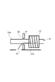
図4に示すように、現像容器2(図3参照)は撹拌室12の下流側(第二方向下流側)の突き当りに現像剤搬送方向に交差する向きに配置された壁部2aを有し、その壁部2aに排出口20が形成されている。排出口20は、図5に示すように、撹拌スクリュー14の回転軸14aの羽根の形成されていない軸部が貫通し、軸部における回転軸14aの外周との間に隙間を有する貫通孔として形成されている。例えば撹拌スクリュー14の回転軸14aの軸径は6mmに、排出口20の直径は8mmに形成される。
<Discharge port>
As shown in FIG. 4, the developing container 2 (see FIG. 3) has a
図4に戻り、排出口は現像容器2の突き当りの壁部2aでなく、撹拌室12の搬送経路途中つまりは第一搬送部141に対向する側壁面の所定高さに形成されることも考えられる。しかしながら、こうした場合には、現像剤が排出口からオーバーフローして排出される以外に撹拌スクリュー14によるはね上げによっても排出され得る。つまり、排出口が現像容器2の突き当りの壁部2aに形成された本実施形態に比べると、撹拌室12に収容された現像剤の量に関わらず現像剤が排出されやすいので、場合によって現像剤が少なくなりすぎる。そうなると、特に現像室11において現像スクリュー13の現像剤搬送方向上流側で十分な量の現像剤が確保されず、現像スリーブ3のコート領域が一律にコートされ難くなる。このコート不良が生じると、画像濃度が薄くなるあるいは画像上に白いスジがあるといったような画像不良が生じ得る。これを避けるには、本実施形態のように、はね上げによる影響が生じ難い現像容器2の突き当りの壁部2aに、排出口20は形成されるのが好ましい。
Returning to FIG. 4, it is considered that the discharge port is formed not at the
<返しスクリュー>
撹拌スクリュー14は、図4に示すように、羽根14bが回転軸14aの周囲に形成されている第一搬送部141の下流(第二方向下流)に、詳しくは羽根14bの下流端部と排出口20との間に、返し部142を有する。返し部142は、回転軸14aの周囲に羽根14bと逆方向に巻かれた返し羽根19bが形成され、第一方向つまりは羽根14bと反対方向に現像剤を搬送する返しスクリュー19である。返しスクリュー19は、例えばスクリューピッチが3mmに、撹拌スクリュー14の回転軸線方向(長手方向)の長さが15mmに形成される。
<Return screw>
As shown in FIG. 4, the
撹拌スクリュー14の第一搬送部141の最下流まで到達した現像剤の量が多い場合に、現像剤の剤面が回転軸14a(回転軸部)と排出口20との隙間の高さまで達すると、隙間から現像剤が排出される。即ち、第一搬送部141によって排出口20へ向かって搬送される現像剤の大部分は、返しスクリュー19により上流側(第二方向上流側)に押し戻されて、排出口20を通過せずに第一連通口16を通って現像室11に受け渡される。他方、返しスクリュー19により押し戻されなかった現像剤は、剤面高さが排出口20の下端よりも高くなることに応じて、排出口20から撹拌室12の下流側に移動する。そして、図5に示すように、壁部2aよりも下流側の撹拌室12の底面部12aには連結口2bが形成されており、現像剤は連結口2bに連結されている不図示の回収容器に回収される。
When the amount of the developer reaching the most downstream side of the first conveying
本実施形態の現像装置1は、現像室11で現像スリーブ3に現像剤を供給し、撹拌室12で現像スリーブ3から現像剤を回収する、所謂、機能分離型の構成を有する。機能分離型の現像装置1では、現像スリーブ3上の現像剤が撹拌室12の長手方向に渡って回収される。このため、現像剤は、現像スリーブ3を介さずに現像室11から撹拌室12に搬送される第一の経路と、現像スリーブ3から直接、撹拌室12に搬送される第二の経路との二つの経路を介して循環され、現像剤量の分布が現像容器2内で不均一となり易い。撹拌室12では下流側に現像剤が溜まり易いため、下流側で現像剤の剤面が高くなりやすい。
The developing
既に述べたように、従来の現像装置では現像剤の流動性が低下した場合、撹拌室12から現像室11への現像剤の受け渡しが抑制されてしまう。そうなると、トナー濃度の低い現像剤が現像スリーブ3に連れ回されることに起因して、濃度ムラのような画像不良が生じやすくなる。また、現像室11において現像スクリュー13の現像剤搬送方向上流側(撹拌スクリュー14の現像剤搬送方向下流側)で十分な量の現像剤が確保されないことから、上述したコート不良に起因する画像不良が生じ得る。
As already described, in the conventional developing device, when the fluidity of the developer is lowered, the delivery of the developer from the stirring
<第三連通口>
そこで、撹拌室12から現像室11への現像剤の受け渡しを抑制させないために、本実施形態では、図3及び図4に示すように、隔壁15に第一連通口16及び第二連通口17の他にも第三連通口18が設けられている。第三連通口18は下流側で第一連通口16に隣接され、また水平方向から視て返しスクリュー19に対向する位置に配置される。例えば、撹拌スクリュー14の回転軸線方向(長手方向)の長さに関し、第一連通口16及び第二連通口17は30mmに、第三連通口18は20mmに形成される。この場合、第三連通口18は、長手方向の長さ(20mm)が返しスクリュー19の長手方向の長さ(15mm)よりも長い。即ち、第三連通口18は返しスクリュー19の長手方向全域に亘る範囲に形成されるのが好ましい。こうすれば、撹拌室12から現像室11への現像剤の受け渡しを向上させることが容易に実現できる。
<Third communication port>
Therefore, in order to prevent the developer from being transferred from the stirring
上述のように、第三連通口18が設けられることによって、撹拌室12から現像室11への現像剤の受け渡しが向上される。ただし、実質的に第三連通口18が従来に比べ単に第一連通口16を下流側に幅広くしただけに過ぎない場合には、現像剤のほとんどが現像室11に受け渡されてしまい、もって排出口20からの現像剤の排出が抑制される。これを避けるため、本実施形態では、図4に示すように、第三連通口18の下端18cが第一連通口16の下端16cよりも上方に形成されている。
As described above, by providing the
即ち、ACR方式の現像装置では、現像剤の剤面高さに応じて排出口20から排出される現像剤量(排出量)が変動する。つまり、排出口20近傍での現像剤の剤面高さが現像剤の排出に影響する。例えば、剤面高さが排出口20よりも常に低い状態であれば、現像剤が補給されても余分な現像剤が排出され難くなる。その結果、現像容器2内の現像剤が必要以上に増加し、現像容器2から現像剤が漏れ出したりあるいはコート不良の原因の1つである凝集塊が生じたりする。従って、排出口20近傍では、場合に応じて現像剤の剤面高さが排出口20に対し適切な高さにまで達しなければならない。しかしながら、上述のように、第三連通口18により単に第一連通口16を幅広くするだけでは、排出口20近傍で剤面高さが排出口20よりも常に低い状態になってしまう。
That is, in the ACR type developing device, the amount of developer discharged from the discharge port 20 (discharge amount) varies according to the developer surface height. That is, the developer surface level near the
そこで、第三連通口18は、下端18cが第一連通口16の下端16cよりも上方に形成される。第三連通口18は、隔壁15のうち返し部142(図4参照)と重なる範囲で現像室11と撹拌室12とを隔てている隔壁部52によって形成されている。それ故、図6に示すように、隔壁部52の最上端52a(下端18cに相当する)が、水平方向から視て排出口20の上端20aと下端20cとの間に到達するように底面部2cから延設されている。この場合、隔壁部52は現像剤の第三連通口18への侵入を防ぐことで、排出口20側へ搬送する現像剤の量を確保する。排出口20側へ搬送される現像剤量は、隔壁部52の高さひいては第三連通口18の下端18cの位置によって決まる。こうすることで、排出口20近傍で現像剤の剤面高さが排出口20の高さにまで到達させ得る。
Therefore, the
以上のように、本実施形態の現像装置1では、隔壁15の第一連通口16の下流側に第三連通口18が設けられる。第三連通口18は、水平方向から視て返しスクリュー19に対向する位置に配置されている。即ち、従来に比べ、撹拌室12から現像室11へ現像剤の受け渡しが行われる第一連通口16が第三連通口18により実質的に拡大される。従って、例え現像剤の流動性が低くなったとしても、撹拌室12から現像室11への現像剤の受け渡しが抑制されないので、現像スリーブ3による現像剤の連れ回りが生じ難い。そして、第三連通口18は、下端18cが第一連通口16の下端16cよりも上方に形成される。これによると、実質的に第一連通口16が返しスクリュー19まで拡大されても、隔壁部52によって第三連通口18への現像剤の侵入が防がれるので、現像剤の排出が抑制され難い。こうして、排出口20からの現像剤の排出を抑制することなく、撹拌室12から現像室11への現像剤の受け渡しが適切に行われることから、もって現像剤の受け渡しや現像剤の排出に起因する画像不良の発生を低減することができる。
As described above, in the developing
<他の実施形態>
なお、上述した実施形態では、各色の感光ドラム10から中間転写ベルト25に各色のトナー像を一次転写した後に、記録材Sに各色の複合トナー像を一括して二次転写する中間転写方式の画像形成装置100を説明したが、これに限らない。例えば、転写材搬送ベルトに担持され搬送される記録材に感光ドラムから直接転写する直接転写方式の画像形成装置であってもよい。
<Other embodiments>
In the above-described embodiment, an intermediate transfer system in which each color toner image is primarily transferred from the
1(1Y〜1K)…現像装置、2…現像容器、2a…壁部、3…現像剤担持体(現像スリーブ)、11…第一室(現像室)、12…第二室(撹拌室)、13…第一搬送スクリュー(現像スクリュー)、14…第二搬送スクリュー(撹拌スクリュー)、14a…軸部(回転軸)、14b…羽根、15…隔壁、16…第一連通口、17…第二連通口、18…第三連通口、20…排出口、100…画像形成装置、141…第一搬送部、142…返し部
DESCRIPTION OF SYMBOLS 1 (1Y-1K) ... developing apparatus, 2 ... developing container, 2a ... wall part, 3 ... developer carrier (developing sleeve), 11 ... first chamber (developing chamber), 12 ... second chamber (stirring chamber) , 13 ... First conveying screw (developing screw), 14 ... Second conveying screw (stirring screw), 14a ... Shaft portion (rotating shaft), 14b ... Blade, 15 ... Partition, 16 ... First series of openings, 17 ... 2nd communication port, 18 ... 3rd communication port, 20 ... Discharge port, 100 ... Image forming apparatus, 141 ... 1st conveyance part, 142 ... Return part
Claims (6)
前記現像剤担持体に現像剤を供給する第一室と、前記第一室とで現像剤の循環経路を形成すると共に前記現像剤担持体から現像剤を回収する第二室と、前記第二室に形成され現像剤を排出する排出口とを有する現像容器と、
前記第一室に配設され、第一方向に現像剤を搬送する第一搬送スクリューと、
水平方向から視て前記第一搬送スクリューと少なくとも一部が重なるように前記第二室に配設され、前記第一方向と反対の第二方向に現像剤を搬送する第一搬送部と、前記第一搬送部の前記第二方向下流側で前記第一搬送部と前記排出口との間に配置され、前記第一方向に現像剤を搬送する返し部とを有する第二搬送スクリューと、
前記現像容器内で前記第一室と前記第二室とを隔て、前記第二方向下流側に前記第二室から前記第一室に現像剤を受け渡す第一連通口と、前記第二方向上流側に前記第一室から前記第二室に現像剤を受け渡す第二連通口と、水平方向から視て少なくとも前記返し部の一部に対向する位置に配置され、下端が前記第一連通口の下端よりも上方に形成された第三連通口とを有する隔壁と、を備える、
ことを特徴とする現像装置。 A developer carrying member that carries the developer and rotates;
A first chamber for supplying a developer to the developer carrier, a second chamber for forming a developer circulation path in the first chamber and collecting the developer from the developer carrier, and the second chamber. A developer container formed in the chamber and having a discharge port for discharging the developer;
A first conveying screw disposed in the first chamber and conveying developer in a first direction;
A first transport unit disposed in the second chamber so as to at least partially overlap the first transport screw when viewed from the horizontal direction, and transports the developer in a second direction opposite to the first direction; A second conveying screw, which is disposed between the first conveying unit and the discharge port on the downstream side in the second direction of the first conveying unit, and has a return unit that conveys the developer in the first direction;
A first series of openings for separating developer from the second chamber to the first chamber on the downstream side in the second direction, separating the first chamber and the second chamber in the developer container; A second communication port for transferring developer from the first chamber to the second chamber on the upstream side in the direction, and a position facing at least a part of the return portion when viewed from the horizontal direction, the lower end being the first A partition wall having a third communication port formed above the lower end of the communication port,
A developing device.
前記排出口は、前記壁部に形成されている、
ことを特徴とする請求項1に記載の現像装置。 The developer container has a wall portion at the end of the second chamber on the downstream side in the second direction,
The discharge port is formed in the wall portion,
The developing device according to claim 1.
前記排出口は、前記第二搬送スクリューの前記羽根が形成されていない軸部が貫通し、前記軸部の外周との間に隙間を有するように形成されている、
ことを特徴とする請求項2に記載の現像装置。 The second conveying screw has a rotating shaft and a spiral blade formed on the rotating shaft,
The discharge port is formed such that a shaft portion where the blades of the second conveying screw are not formed passes therethrough and has a gap with the outer periphery of the shaft portion.
The developing device according to claim 2.
ことを特徴とする請求項3に記載の現像装置。 The third communication port is formed so that the lower end is between the upper end and the lower end of the discharge port as viewed from the horizontal direction.
The developing device according to claim 3.
ことを特徴とする請求項1乃至4のいずれか1項に記載の現像装置。 The second conveying screw has a lower end disposed above the lower end of the first conveying screw as viewed from the horizontal direction.
The developing device according to claim 1, wherein
前記現像剤担持体に現像剤を供給する第一室と、前記第一室とで現像剤の循環経路を形成すると共に前記現像剤担持体から現像剤を回収する第二室と、前記第二室に形成され現像剤を排出する排出口とを有する現像容器と、
前記第一室に配設され、第一方向に現像剤を搬送する第一搬送スクリューと、
水平方向から視て前記第一搬送スクリューと少なくとも一部が重なるように前記第二室に配設され、前記第一方向と反対の第二方向に現像剤を搬送する第一搬送部と、前記第一搬送部の前記第二方向下流側で前記第一搬送部と前記排出口との間に配置され、前記第一方向に現像剤を搬送する返し部とを有する第二搬送スクリューと、
前記現像容器内で前記第一室と前記第二室とを隔て、前記第二方向下流側に前記第二室から前記第一室に現像剤を受け渡す第一連通口と、前記第二方向上流側に前記第一室から前記第二室に現像剤を受け渡す第二連通口とを有する隔壁と、を備え、
前記第一連通口は、水平方向から視て前記第一搬送部の前記第二方向下流側の一部と前記返し部の一部とに対向するように形成されている、
ことを特徴とする現像装置。
A developer carrying member that carries the developer and rotates;
A first chamber for supplying a developer to the developer carrier, a second chamber for forming a developer circulation path in the first chamber and collecting the developer from the developer carrier, and the second chamber. A developer container formed in the chamber and having a discharge port for discharging the developer;
A first conveying screw disposed in the first chamber and conveying developer in a first direction;
A first transport unit disposed in the second chamber so as to at least partially overlap the first transport screw when viewed from the horizontal direction, and transports the developer in a second direction opposite to the first direction; A second conveying screw, which is disposed between the first conveying unit and the discharge port on the downstream side in the second direction of the first conveying unit, and has a return unit that conveys the developer in the first direction;
A first series of openings for separating developer from the second chamber to the first chamber on the downstream side in the second direction, separating the first chamber and the second chamber in the developer container; A partition wall having a second communication port for transferring developer from the first chamber to the second chamber on the upstream side in the direction,
The first continuous passage is formed so as to face a part of the first transport part on the downstream side in the second direction and a part of the return part as viewed from the horizontal direction.
A developing device.
Priority Applications (3)
| Application Number | Priority Date | Filing Date | Title |
|---|---|---|---|
| JP2016086443A JP6755699B2 (en) | 2016-04-22 | 2016-04-22 | Developer |
| US15/467,252 US10126683B2 (en) | 2016-04-22 | 2017-03-23 | Developing apparatus |
| US16/145,351 US20190033752A1 (en) | 2016-04-22 | 2018-09-28 | Developing apparatus |
Applications Claiming Priority (1)
| Application Number | Priority Date | Filing Date | Title |
|---|---|---|---|
| JP2016086443A JP6755699B2 (en) | 2016-04-22 | 2016-04-22 | Developer |
Publications (3)
| Publication Number | Publication Date |
|---|---|
| JP2017194645A true JP2017194645A (en) | 2017-10-26 |
| JP2017194645A5 JP2017194645A5 (en) | 2019-05-30 |
| JP6755699B2 JP6755699B2 (en) | 2020-09-16 |
Family
ID=60090176
Family Applications (1)
| Application Number | Title | Priority Date | Filing Date |
|---|---|---|---|
| JP2016086443A Active JP6755699B2 (en) | 2016-04-22 | 2016-04-22 | Developer |
Country Status (2)
| Country | Link |
|---|---|
| US (2) | US10126683B2 (en) |
| JP (1) | JP6755699B2 (en) |
Families Citing this family (2)
| Publication number | Priority date | Publication date | Assignee | Title |
|---|---|---|---|---|
| US11378898B2 (en) | 2018-11-16 | 2022-07-05 | Hewlett-Packard Development Company, L.P. | Magnetic carrier bead separation |
| JP2023078737A (en) | 2021-11-26 | 2023-06-07 | キヤノン株式会社 | Development device |
Family Cites Families (19)
| Publication number | Priority date | Publication date | Assignee | Title |
|---|---|---|---|---|
| JPS59100471A (en) | 1982-12-01 | 1984-06-09 | Fuji Xerox Co Ltd | Developing device for electrophotographic copying machine |
| JP5273439B2 (en) | 2008-02-12 | 2013-08-28 | 株式会社リコー | Developing device, process cartridge, and image forming apparatus |
| US8099026B2 (en) * | 2008-07-31 | 2012-01-17 | Ricoh Company, Limited | Development device and image forming apparatus capable of reducing stress applied to developer |
| JP5206398B2 (en) | 2008-12-25 | 2013-06-12 | コニカミノルタビジネステクノロジーズ株式会社 | Waste powder collection container, connection structure to waste powder collection container, developing device, and image forming apparatus |
| JP5305233B2 (en) | 2009-02-24 | 2013-10-02 | 株式会社リコー | Developing device, process cartridge, and image forming apparatus |
| JP4846828B2 (en) * | 2009-06-22 | 2011-12-28 | シャープ株式会社 | Developing device and image forming apparatus using the same |
| JP5003780B2 (en) * | 2010-03-24 | 2012-08-15 | コニカミノルタビジネステクノロジーズ株式会社 | Developing device and image forming apparatus |
| US20120014718A1 (en) * | 2010-07-15 | 2012-01-19 | Toshiba Tec Kabushiki Kaisha | Developing device, image forming apparatus, and image forming method |
| JP5267581B2 (en) * | 2011-01-20 | 2013-08-21 | コニカミノルタビジネステクノロジーズ株式会社 | Developing device and image forming apparatus |
| JP5885541B2 (en) * | 2012-03-01 | 2016-03-15 | キヤノン株式会社 | Image forming apparatus |
| US9335662B2 (en) * | 2013-01-29 | 2016-05-10 | Ricoh Company, Ltd. | Developing device and image forming apparatus and process cartridge incorporating same |
| JP6108165B2 (en) * | 2013-06-26 | 2017-04-05 | 株式会社リコー | Developing device, process unit, and image forming apparatus |
| JP6207258B2 (en) * | 2013-06-28 | 2017-10-04 | キヤノン株式会社 | Development device |
| JP6261294B2 (en) | 2013-11-15 | 2018-01-17 | キヤノン株式会社 | Development device |
| JP6195370B2 (en) * | 2013-11-21 | 2017-09-13 | キヤノン株式会社 | Development device |
| JP2016024353A (en) | 2014-07-22 | 2016-02-08 | キヤノン株式会社 | Development device |
| JP6403584B2 (en) * | 2015-01-22 | 2018-10-10 | キヤノン株式会社 | Development device |
| JP6330688B2 (en) * | 2015-02-19 | 2018-05-30 | 京セラドキュメントソリューションズ株式会社 | Developing device and image forming apparatus including the same |
| JP6308175B2 (en) * | 2015-06-19 | 2018-04-11 | 京セラドキュメントソリューションズ株式会社 | Developing device and image forming apparatus including the same |
-
2016
- 2016-04-22 JP JP2016086443A patent/JP6755699B2/en active Active
-
2017
- 2017-03-23 US US15/467,252 patent/US10126683B2/en active Active
-
2018
- 2018-09-28 US US16/145,351 patent/US20190033752A1/en not_active Abandoned
Also Published As
| Publication number | Publication date |
|---|---|
| US20190033752A1 (en) | 2019-01-31 |
| US10126683B2 (en) | 2018-11-13 |
| JP6755699B2 (en) | 2020-09-16 |
| US20170308004A1 (en) | 2017-10-26 |
Similar Documents
| Publication | Publication Date | Title |
|---|---|---|
| JP6604992B2 (en) | Developing device and image forming apparatus | |
| US9329523B2 (en) | Developing apparatus | |
| JP6025383B2 (en) | Development device | |
| JP6794131B2 (en) | Developer | |
| JP6755699B2 (en) | Developer | |
| JP6261314B2 (en) | Development device | |
| JP2017211611A (en) | Developing device | |
| JP5868375B2 (en) | Developing device and image forming apparatus | |
| JP2018018058A (en) | Developing device | |
| JP7043270B2 (en) | Developer | |
| JP6627735B2 (en) | Stirring / conveying member, developing device having the same, and image forming apparatus | |
| JP6529244B2 (en) | Development device | |
| JP2018036539A (en) | Developing device | |
| JP2019028315A (en) | Developing device | |
| JP2018132654A (en) | Development apparatus | |
| JP2018155856A (en) | Development apparatus | |
| JP7034731B2 (en) | Developer | |
| JP7039300B2 (en) | Developer | |
| JP2011141368A (en) | Developing apparatus, process cartridge, and image forming apparatus | |
| JP2018036537A (en) | Developing device | |
| JP2017156588A (en) | Developing device | |
| JP2018005029A (en) | Developing device and image forming apparatus including the same | |
| JP6627736B2 (en) | Stirring / conveying member, developing device having the same, and image forming apparatus | |
| JP6347828B2 (en) | Development device | |
| JP2003295602A (en) | Developing device and image forming apparatus |
Legal Events
| Date | Code | Title | Description |
|---|---|---|---|
| A521 | Request for written amendment filed |
Free format text: JAPANESE INTERMEDIATE CODE: A523 Effective date: 20190417 |
|
| A621 | Written request for application examination |
Free format text: JAPANESE INTERMEDIATE CODE: A621 Effective date: 20190417 |
|
| RD02 | Notification of acceptance of power of attorney |
Free format text: JAPANESE INTERMEDIATE CODE: A7422 Effective date: 20200206 |
|
| A977 | Report on retrieval |
Free format text: JAPANESE INTERMEDIATE CODE: A971007 Effective date: 20200207 |
|
| RD04 | Notification of resignation of power of attorney |
Free format text: JAPANESE INTERMEDIATE CODE: A7424 Effective date: 20200207 |
|
| A131 | Notification of reasons for refusal |
Free format text: JAPANESE INTERMEDIATE CODE: A131 Effective date: 20200225 |
|
| A521 | Request for written amendment filed |
Free format text: JAPANESE INTERMEDIATE CODE: A523 Effective date: 20200403 |
|
| A131 | Notification of reasons for refusal |
Free format text: JAPANESE INTERMEDIATE CODE: A131 Effective date: 20200519 |
|
| A521 | Request for written amendment filed |
Free format text: JAPANESE INTERMEDIATE CODE: A523 Effective date: 20200701 |
|
| TRDD | Decision of grant or rejection written | ||
| A01 | Written decision to grant a patent or to grant a registration (utility model) |
Free format text: JAPANESE INTERMEDIATE CODE: A01 Effective date: 20200728 |
|
| A61 | First payment of annual fees (during grant procedure) |
Free format text: JAPANESE INTERMEDIATE CODE: A61 Effective date: 20200826 |
|
| R151 | Written notification of patent or utility model registration |
Ref document number: 6755699 Country of ref document: JP Free format text: JAPANESE INTERMEDIATE CODE: R151 |