JP4641237B2 - Multi-degree-of-freedom actuator - Google Patents
Multi-degree-of-freedom actuator Download PDFInfo
- Publication number
- JP4641237B2 JP4641237B2 JP2005280681A JP2005280681A JP4641237B2 JP 4641237 B2 JP4641237 B2 JP 4641237B2 JP 2005280681 A JP2005280681 A JP 2005280681A JP 2005280681 A JP2005280681 A JP 2005280681A JP 4641237 B2 JP4641237 B2 JP 4641237B2
- Authority
- JP
- Japan
- Prior art keywords
- output shaft
- axis
- swing
- casing
- connecting member
- Prior art date
- Legal status (The legal status is an assumption and is not a legal conclusion. Google has not performed a legal analysis and makes no representation as to the accuracy of the status listed.)
- Expired - Fee Related
Links
Images


Landscapes
- Connection Of Motors, Electrical Generators, Mechanical Devices, And The Like (AREA)
Description
本発明は多自由度アクチュエータに係り、特に出力軸を2軸(X軸及びY軸)方向から揺動させるように構成された多自由度アクチュエータに関する。 The present invention relates to a multi-degree-of-freedom actuator, and more particularly to a multi-degree-of-freedom actuator configured to swing an output shaft from two directions (X-axis and Y-axis).
従来の多自由度アクチュエータとしては、例えば、水平軸回りを駆動する第1のリニアモータと垂直軸回りを駆動する第2のリニアモータとを有し、出力軸を水平軸回りと垂直軸回りの2軸方向から駆動する構成のものがある(例えば、特許文献1参照)。 As a conventional multi-degree-of-freedom actuator, for example, it has a first linear motor that drives around a horizontal axis and a second linear motor that drives around a vertical axis, and an output shaft around a horizontal axis and a vertical axis. There is a configuration that drives from two axial directions (see, for example, Patent Document 1).
この多自由度アクチュエータでは、第1のリニアモータがベースに支持され、第2のリニアモータが第1のリニアモータに駆動される第1の移動子に支持され、第2のリニアモータに駆動される第2の移動子がフレームを介して出力軸を駆動するように配置されている。そのため、従来は、第1のリニアモータとフレームとの間に第2のリニアモータが介在しており、第1のリニアモータが第1の移動子を駆動する場合、第2のリニアモータ及びフレームを介して出力軸を駆動するため、2つのリニアモータが直交する2軸(X軸、Y軸)を独立に駆動するのではなく、第1のリニアモータを駆動すると第2のリニアモータも移動してしまう。よって、第1のリニアモータは、第1の移動子だけでなく、第2のリニアモータの重量も含む荷重に対する駆動力を発生させるように構成されている。
上記従来の多自由度アクチュエータでは、ベース側に設けられた第1のリニアモータが第2のリニアモータを介して出力軸を駆動する構成であるので、第2のリニアモータの重量を駆動するために余分な動力が必要であり、第1のリニアモータが大型化(大容量化)すると共に、第1のリニアモータを支持するベースの剛性も高めることになる。 In the conventional multi-degree-of-freedom actuator, since the first linear motor provided on the base side drives the output shaft via the second linear motor, the weight of the second linear motor is driven. Therefore, the first linear motor is increased in size (capacity), and the rigidity of the base that supports the first linear motor is increased.
そのため、従来は、出力軸の動作精度を高めるためにベースやフレームの剛性を高めると、重量増大を招くので、第1のリニアモータを大型化しなければならず、第1のリニアモータを大型化を回避するためにベースやフレームの剛性を下げた場合には、出力軸の動作精度が低下するという問題がある。 Therefore, conventionally, increasing the rigidity of the base and the frame to increase the operation accuracy of the output shaft causes an increase in weight, so the first linear motor must be enlarged, and the first linear motor is enlarged. When the rigidity of the base or the frame is lowered in order to avoid this, there is a problem that the operation accuracy of the output shaft is lowered.
そこで、本発明は上記課題を解決した多自由度アクチュエータを提供することを目的とする。 Therefore, an object of the present invention is to provide a multi-degree-of-freedom actuator that solves the above-described problems.
上記課題を解決するため、本発明は以下のような手段を有する。 In order to solve the above problems, the present invention has the following means.
請求項1記載の発明は、ケーシングと、先端が該ケーシングの内部に挿入され、基端が前記ケーシングの開口部より外部に延在する出力軸と、前記ケーシングの内部に収納され、前記出力軸の軸線と直交する軸回りに前記出力軸の基端を揺動可能に支持する第1の揺動機構と、前記ケーシングの内部で前記第1の揺動機構と交差するように前記出力軸の軸線上に対向配置され、前記出力軸の軸線と直交する他方向の軸回りに前記出力軸の基端を揺動可能に支持する第2の揺動機構と、前記第1の揺動機構を駆動して前記出力軸を一方向に揺動させる第1の駆動部と、前記第2の揺動機構を駆動して前記出力軸を他方向に揺動させる第2の駆動部と、を有し、前記第1の揺動機構は、前記出力軸の基端に対し直交する軸回りの揺動をガイドする第1の曲面ガイドと、前記出力軸の基端が固定され、前記出力軸の軸線と直交する方向に延在形成された第1の連結部材と、前記第1の連結部材の両端部に回動可能に連結され、前記第1の曲面ガイドに揺動可能に支持される第1の移動子と、を有し、前記第2の揺動機構は、前記出力軸の基端に対し前記第1の曲面ガイドと異なる位置で前記出力軸の基端に対し直交する他の軸回りの揺動をガイドする第2の曲面ガイドと、前記出力軸の軸線上で前記第1の連結部材と交差するように対向配置され、前記第1の連結部材に対して相対的に回動可能に組み合わされた第2の連結部材と、
前記第2の連結部材の両端部に回動可能に連結され、前記第2の曲面ガイドに揺動可能に支持される第2の移動子と、を有し、前記第1の揺動機構と前記第2の揺動機構は、前記第1の駆動部及び前記第2の駆動部の駆動力により前記出力軸が揺動動作する際、前記出力軸の揺動方向に応じて相対的に回動することを特徴とする。
The invention according to
A second moving member rotatably connected to both ends of the second connecting member and supported by the second curved surface guide so as to be swingable; and the first swinging mechanism; The second swing mechanism rotates relatively according to the swing direction of the output shaft when the output shaft swings by the driving force of the first drive unit and the second drive unit. It is characterized by moving.
請求項2記載の発明は、ケーシングと、先端が該ケーシングの内部に挿入され、基端が前記ケーシングの開口部より外部に延在する出力軸と、前記ケーシングの内部に設けられ、前記出力軸の基端に対し直交する軸回りの揺動をガイドする一対の第1の曲面ガイドと、前記ケーシングの内部で前記出力軸の基端に対し前記一対の第1の曲面ガイドと異なる位置で前記出力軸の基端に対し直交する他の軸回りの揺動をガイドする一対の第2の曲面ガイドと、前記出力軸の基端が固定され、前記出力軸の軸線と直交する方向に延在形成された第1の連結部材と、前記出力軸の軸線上で前記第1の連結部材と交差するように対向配置され、前記第1の連結部材に対して相対的に回動可能に組み合わされた第2の連結部材と、前記第1の連結部材の両端部に回動可能に連結され、前記一対の第1の曲面ガイドに揺動可能に支持される一対の第1の移動子と、前記第2の連結部材の両端部に回動可能に連結され、前記一対の第2の曲面ガイドに揺動可能に支持される一対の第2の移動子と、前記第1の移動子を駆動して前記出力軸を一方向に揺動させる第1の駆動部と、前記第2の移動子を駆動して前記出力軸を他方向に揺動させる第2の駆動部と、を有することを特徴とする。 According to a second aspect of the present invention, there is provided a casing, an output shaft having a distal end inserted into the casing, a proximal end extending outside from an opening of the casing, the interior of the casing, and the output shaft. A pair of first curved surface guides for guiding swinging about an axis orthogonal to the base end of the output shaft, and a position different from the pair of first curved surface guides with respect to the base end of the output shaft inside the casing. A pair of second curved surface guides that guide the swing around another axis orthogonal to the base end of the output shaft, and the base end of the output shaft are fixed and extend in a direction orthogonal to the axis of the output shaft The first connecting member formed is opposed to the first connecting member so as to intersect the first connecting member on the axis of the output shaft, and is combined so as to be rotatable relative to the first connecting member. Both the second connecting member and the first connecting member A pair of first movers that are pivotably connected to the pair and supported by the pair of first curved surface guides so as to be swingable, and pivotally connected to both ends of the second connecting member. , A pair of second movable elements supported to be swingable by the pair of second curved surface guides, and a first drive for driving the first movable element to swing the output shaft in one direction. And a second drive unit that drives the second moving element to swing the output shaft in the other direction.
請求項3記載の発明は、前記第1の移動子と前記第2の移動子は、同一の曲率半径に沿って揺動することを特徴とする。 The invention according to claim 3 is characterized in that the first moving element and the second moving element swing along the same radius of curvature.
請求項4記載の発明は、前記第1の連結部材と前記第2の連結部材は、前記出力軸と同軸上に配された前記第1の連結部材の中央孔及び前記第2の連結部材の中央孔を貫通する筒状軸受を介して回動可能に連結されたことを特徴とする。 According to a fourth aspect of the present invention, the first connecting member and the second connecting member are formed so that the center hole of the first connecting member and the second connecting member arranged coaxially with the output shaft. It is connected so as to be rotatable through a cylindrical bearing that penetrates the central hole.
請求項5記載の発明は、前記第1の曲面ガイド及び前記第2の曲面ガイドは、前記移動子の揺動位置を検出する位置検出手段を有することを特徴とする。 The invention according to claim 5 is characterized in that the first curved surface guide and the second curved surface guide have position detecting means for detecting a swinging position of the moving element.
請求項6記載の発明は、前記第1の曲面ガイド及び前記第2の曲面ガイドは、同一中心からの曲率半径上に形成されたガイド面を有することを特徴とする。 The invention according to claim 6 is characterized in that the first curved surface guide and the second curved surface guide have guide surfaces formed on a radius of curvature from the same center.
請求項7記載の発明は、前記ガイド面には、前記移動子の揺動動作に伴う摺動抵抗を軽減する低摩擦部材が設けられたことを特徴とする。
The invention according to
請求項8記載の発明は、前記第1の駆動部及び前記第2の駆動部は、供給される印加電圧に応じた電磁力による駆動力を発生し、前記移動子を駆動する駆動手段を有することを特徴とする。 According to an eighth aspect of the present invention, the first driving unit and the second driving unit include a driving unit that generates a driving force by an electromagnetic force corresponding to a supplied applied voltage and drives the moving element. It is characterized by that.
請求項9記載の発明は、前記第1の駆動部及び前記第2の駆動部は、供給される作動流体の圧力により駆動力を発生し、前記移動子を駆動する駆動手段を有することを特徴とする。
The invention according to
請求項10記載の発明は、ケーシングと、該ケーシングの内部に挿入されたテーブルと、前記ケーシングの軸線と直交する一方向の軸回りに前記テーブルを揺動可能に支持する第1の揺動機構と、前記第1の揺動機構と交差するように前記テーブルの軸線上に対向配置され、前記テーブルの軸線と直交する他方向の軸回りに前記テーブルを揺動可能に支持する第2の揺動機構と、前記一方向の軸回りに湾曲した第1のシリンダ室と、作動流体の圧力により前記第1のシリンダ室に沿って回動する第1のピストンとを有し、前記第1のピストンの回動と共に前記第1の揺動機構を駆動して前記テーブルを一方向に揺動させる第1の駆動部と、前記他方向の軸回りに湾曲した第2のシリンダ室と、作動流体の圧力により該第2のシリンダ室に沿って回動する第2のピストンとを有し、前記第2のピストンの回動と共に前記第2の揺動機構を駆動して前記テーブルを他方向に揺動させる第2の駆動部と、を有し、前記第1の揺動機構と前記第2の揺動機構は、前記第1の駆動部及び前記第2の駆動部の駆動力により前記テーブルが揺動動作する際、前記テーブルの揺動方向に応じて相対的に回動することを特徴とする。
The invention according to
本発明によれば、第1の駆動部に駆動される第1の揺動機構と第2の駆動部に駆動される第2の揺動機構とが夫々独立に駆動され、且つ第1の揺動機構と第2の揺動機構が出力軸の揺動方向に応じて相対的に回動するように連結されているので、第1の揺動機構と第2の揺動機構が互いに干渉しないように動作することができ、これにより、第1の駆動部及び第2の駆動部を小型化(小容量化)することが可能になる。また、第1の駆動部及び第2の駆動部の小型化により出力軸の動作精度を確保しつつ、駆動部を支持するフレームの剛性を下げて軽量化を図れることも可能になる。 According to the present invention, the first swing mechanism driven by the first drive unit and the second swing mechanism driven by the second drive unit are driven independently, and the first swing mechanism is driven. Since the moving mechanism and the second swinging mechanism are coupled so as to rotate relative to the swinging direction of the output shaft, the first swinging mechanism and the second swinging mechanism do not interfere with each other. Accordingly, the first driving unit and the second driving unit can be reduced in size (capacity reduction). Further, the first drive unit and the second drive unit can be reduced in size, and the rigidity of the frame that supports the drive unit can be reduced while reducing the weight while securing the operation accuracy of the output shaft.
また、本発明によれば、第1の揺動機構が、第1の曲面ガイドと、第1の連結部材と、第1の移動子とを有し、第2の揺動機構が、第2の曲面ガイドと、第2の連結部材と、第2の移動子とを有するため、第1の連結部材と第2の連結部材とが干渉しないように動作することができ、これにより、少ない部品構成で各軸回りの駆動系を独立に配置することができる。 According to the present invention, the first swing mechanism has the first curved surface guide, the first connecting member, and the first moving member, and the second swing mechanism is the second Since the curved surface guide, the second connecting member, and the second moving member are provided, the first connecting member and the second connecting member can be operated so as not to interfere with each other, thereby reducing the number of components. With the configuration, the drive system around each axis can be arranged independently.
また、本発明によれば、第1の曲面ガイド及び第2の曲面ガイドに移動子の揺動位置を検出する位置検出手段を有するため、移動子の位置を正確に検出することができる。 Further, according to the present invention, since the first curved surface guide and the second curved surface guide have the position detecting means for detecting the swinging position of the moving element, the position of the moving element can be detected accurately.
また、本発明によれば、第1の曲面ガイド及び第2の曲面ガイドのガイド面に移動子の揺動動作に伴う摺動抵抗を軽減する低摩擦部材を設けたため、移動子を駆動させる際の摩擦抵抗が軽減され、その分、第1の駆動部及び第2の駆動部の小型化(小容量化)を図ることが可能になる。 Further, according to the present invention, since the low friction member for reducing the sliding resistance associated with the swinging motion of the moving element is provided on the guide surfaces of the first curved surface guide and the second curved surface guide, Thus, it is possible to reduce the size (capacity) of the first drive unit and the second drive unit.
以下、図面を参照して本発明を実施するための最良の形態について説明する。 The best mode for carrying out the present invention will be described below with reference to the drawings.
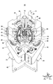
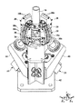
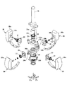
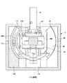
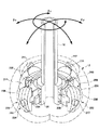
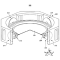
図1は本発明になる多自由度アクチュエータの実施例1を示す斜視図である。図2はケーシングを外した状態を示す斜視図である。図3はケーシング内部に収納される機構の分解斜視図である。
FIG. 1 is a perspective
図1乃至図3に示されるように、多自由度アクチュエータ10は、ケーシング12と、ケーシング12の開口部14より外部に延在する出力軸16と、θx方向に出力軸16を揺動可能に支持する第1の揺動機構18と、第1の揺動機構18と交差するように対向配置されθy方向に出力軸16の基端を揺動可能に支持する第2の揺動機構20と、第1の揺動機構18をθx方向に揺動させる第1の駆動部22と、第2の揺動機構20をθy方向に揺動させる第2の駆動部24とを有する。
As shown in FIGS. 1 to 3, the multi-degree-of-
ケーシング12は、箱型に形成され、内部に各機構を収納する空間が形成されている。出力軸16は、基端がケーシング12の内部に挿入され、先端がケーシング12の開口部14より外部に延在するように取り付けられている。第1の揺動機構18は、ケーシング12の内部に収納され出力軸16の軸線と直交するX方向の軸回り(θx方向)に出力軸16の基端を揺動可能に支持している。また、第2の揺動機構20は、ケーシング12の内部で第1の揺動機構18と交差するように出力軸16の軸線上に対向配置され、出力軸16の軸線と直交するY方向の軸回り(θy方向)に出力軸16の基端を揺動可能に支持している。
The
また、第1の駆動部22は、ケーシング12の下部に取り付けられており、第1の揺動機構18を駆動して出力軸16をθx方向に揺動させるように構成されている。また、第2の駆動部24は、第2の揺動機構20を駆動して出力軸16をθy方向に揺動させるように構成されている。
The
ここで、多自由度アクチュエータ10を構成する上記各機構について、さらに詳細に説明する。
Here, each of the mechanisms constituting the multi-degree-of-
第1の揺動機構18は、出力軸16の基端に対し直交するX方向の軸回り(θx方向)の揺動をガイドする一対の第1の曲面ガイド26と、出力軸16の基端が固定され、出力軸16の軸線と直交するY方向に延在形成された第1の連結部材28と、第1の連結部材28の両端部に回動可能に連結され第1の曲面ガイド26に揺動可能に支持される一対の第1の移動子30とを有する。
The
第2の揺動機構20は、出力軸16の基端に対し第1の曲面ガイド26と異なる位置で出力軸16の基端に対し直交するY方向の軸回り(θy方向)の揺動をガイドする一対の第2の曲面ガイド32と、出力軸16の軸線上で第1の連結部材28と交差するように対向配置され、第1の連結部材28に対して相対的に回動可能に組み合わされた第2の連結部材34と、第2の連結部材34の両端部に回動可能に連結され第2の曲面ガイド32に揺動可能に支持される一対の第2の移動子36とを有する。
The
連結部材28,34は、軸受部38を介して上下方向で回動可能に対向するように設けられている。軸受部38は、出力軸16の下端に結合された円筒軸38aと、円筒軸38aの外周に嵌合する一対のころがり軸受38bとを有する。そして、連結部材28,34の中央孔28a,34aは、夫々ころがり軸受38bの外輪が嵌合して個別に回動可能に支持されている。そのため、連結部材28,34は、駆動部22,24により移動子30,36を揺動動作する際、移動子30,36の揺動動作に応じて相対的に回動することができる。
The connecting
また、連結部材28,34は、夫々両端より側方に突出する円筒形状の軸28b,34bを有する。そして、軸28b,34bは、移動子30,36の内側側面の取付孔30c,36cに挿入された軸受31,37により回動可能に軸承されている。また、軸受31,37は、押さえ板33,35により取付孔30c,36cから脱落しないように保持されている。
Further, the connecting
そのため、連結部材28,34は、夫々の両端に設けられた軸28b,34bが移動子30,36の内側側面に対して出力軸16の軸線と直交するX軸回り(θx方向)、Y軸回り(θy方向)に回転可能に支持されている。これにより、連結部材28,34は、移動子30,36が揺動動作する際に、θx方向、θy方向の揺動動作が互いに干渉されることなく各軸回りに独立に揺動することが可能になる。そのため、多自由度アクチュエータ10では、駆動部22,24を小型化(小容量化)することが可能になると共に、駆動部22,24の小型化により出力軸16の動作精度を確保しつつケーシング12などの剛性を下げても出力軸16の動作精度を確保できるので、軽量化も図れる。
Therefore, the connecting
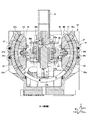
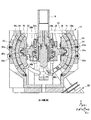
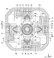
図4はケーシングを水平方向に切断した横断面図である。図5は図4中A−A線に沿う縦断面図である。図6は図4中B−B線に沿う縦断面図である。図4乃至図6に示されるように、移動子30,36は、曲面ガイド26,32により同一の曲率半径に沿って揺動させるようにガイドされる円弧状に形成された摺動面30a,36aを有する。さらに、曲面ガイド26,32のガイド面26a,32aと、第1の移動子30及び第2の移動子36の摺動面30a,36aには、V字状溝26b,32b,30b,36bが形成されており、互いに対向するV字状溝26bと30bとの間及びV字状溝32bと36bとの間には、ころがり軸受40が設けられている。
FIG. 4 is a cross-sectional view of the casing cut in the horizontal direction. FIG. 5 is a longitudinal sectional view taken along line AA in FIG. 6 is a longitudinal sectional view taken along line BB in FIG. As shown in FIGS. 4 to 6, the moving
従って、曲面ガイド26,32のガイド面26a,32aと移動子30,36の摺動面30a,36aとの間は、ころがり軸受40により摺動抵抗(摩擦)が軽減される。これにより、移動子30,36は、ガイド面26a,32aに対して低摩擦で駆動される。
Therefore, the sliding resistance (friction) is reduced by the rolling
そして、移動子30,36は、夫々同一の曲率半径で下方に延在形成された円弧状部30b,36bを有する。この円弧状部30b,36bは、駆動部22,24からの駆動力が伝達され、移動子30,36と共にガイド面26a,32aに沿って揺動する。さらに、移動子30,36の側面には、ケーシング12の内部に当接して揺動範囲を規制されるストッパピン30d,36dを有する。
The
また、移動子30,36がガイド面26a,32aに沿って揺動する際、回転中心から水平方向に対応するガイド面26a,32aの中間位置を基準位置とすると、この基準位置での第1の連結部材28と第2の連結部材34とは、90度の角度で交差している。そして、移動子30,36が中間位置より上方または下方に揺動すると、第1の移動子30の移動側端部と第2の移動子36の移動側端部との水平方向距離が狭くなり、第1の連結部材28と第2の連結部材34との交差角度が90以下に変化する。
Further, when the
従って、連結部材28,34は、ころがり軸受38により出力軸16の軸線に対して回動可能に設けられているので、移動子30,36の揺動動作に伴って交差角度を変化させるように出力軸16の軸回り(θz方向)に回動する。これにより、出力軸16が軸線(Z軸)に対してどの方向に揺動しても移動子30,36は、連結部材28,34の水平方向距離の変化に規制されず、スムーズにガイド面26a,32aを摺動して揺動動作することができる。
Accordingly, since the connecting
また、曲面ガイド26,32上端には、移動子30,36の位置を検出するための位置センサ68,70が取り付けられている。この位置センサ68,70は、移動子30,36に設けられた光反射スリット板(図示せず)に対して検出光を照射し、反射光の有無によって得られるパルス数をカウントしてθx方向揺動位置、θy方向揺動位置の検出を行なうように構成されている。
Further,
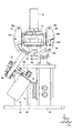
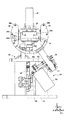
ここで、駆動部22,24の構成について説明する。図7はθy方向の駆動部の構成を示す図である。図8はθx方向の駆動部の構成を示す図である。
Here, the configuration of the
図7に示されるように、第1の駆動部22は、ケーシング12を支持するベース42の傾斜ブラケット44に取り付けられたサーボモータ48と、サーボモータ48により回転駆動される駆動側プーリ52と、傾斜ブラケット44に支持された駆動軸55に係合する従動側プーリ56と、駆動側プーリ52と従動側プーリ56との間に巻き掛けされたタイミングベルト60と、駆動軸55の上端部に嵌合する駆動ギヤ64とを有する。
As shown in FIG. 7, the
駆動ギヤ64は、移動子30の円弧状部30bに設けられたラック(図示せず)に噛合するかさ歯車からなり、サーボモータ48からの回転駆動力を円弧状部30bに伝達する。
The drive gear 64 is a bevel gear that meshes with a rack (not shown) provided on the
図8に示されるように、第2の駆動部24は、ケーシング12を支持するベース42の傾斜ブラケット46に取り付けられたサーボモータ50と、サーボモータ50により回転駆動される駆動側プーリ54と、傾斜ブラケット46に支持された駆動軸57に係合する従動側プーリ58と、駆動側プーリ54と従動側プーリ58との間に巻き掛けされたタイミングベルト62と、駆動軸57の上端部に嵌合する駆動ギヤ66とを有する。
As shown in FIG. 8, the
駆動ギヤ66は、移動子36の円弧状部36bに設けられたラック(図示せず)に噛合するかさ歯車からなり、サーボモータ50からの回転駆動力を円弧状部36bに伝達する。
The drive gear 66 is a bevel gear that meshes with a rack (not shown) provided on the arc-shaped
図9は実施例1の制御系を示すブロック図である。図9に示されるように、アクチュエータ10では、入力手段72により出力軸16の揺動方向及び揺動角度の指令データが制御部74に入力されると、制御部74は、入力された指令データに応じた制御データ(モータ制御信号)を生成してサーボモータ48,50に出力する。これにより、サーボモータ48,50は、制御部74から入力された制御信号に応じた回動角まで駆動側プーリ52,54を駆動する。駆動側プーリ52,54の回転駆動力は、タイミングベルト60,62、従動側プーリ56,58、駆動ギヤ64,66を介して移動子30,36に伝達される。
FIG. 9 is a block diagram illustrating the control system of the first embodiment. As shown in FIG. 9, in the
そして、固定側の曲面ガイド26,32に対する移動子30,36の揺動動作位置は、位置センサ68,70によって測定され、位置センサ68,70から出力された検出信号により得られた揺動位置データは制御部74にフィードバックされる。制御部74は、このフィードバック信号に基づいてサーボモータ48,50に対する制御信号を補正して移動子30,36の揺動動作位置を位置決めする。
Then, the swinging operation position of the
このように、移動子30,36の揺動動作は、連結部材28,34を介して出力軸16に伝達され、出力軸16を入力手段72から指令された揺動位置に揺動させることができる。
As described above, the swinging motion of the
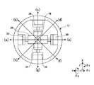
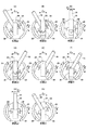
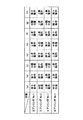
ここで、上記多自由度アクチュエータ10の動作について説明する。図10は多自由度アクチュエータ10の構成を簡略化して出力軸16の各動作方向(a)〜(h)を示す平面図である。図11は出力軸16の各動作方向(a)〜(h)に応じた移動子30,36の動作状態を個別に示す図である。図12は出力軸16の各動作方向(a)〜(h)に応じたサーボモータ48,50の回転制御方向を模式的に示す図である。
Here, the operation of the multi-degree-of-
図10に示されるように、出力軸16を例えば、45度ずつ8方向に揺動させた場合の各動作方向は(a)〜(h)に示す方向とする。この各動作方向(a)〜(h)に応じた移動子30,36の動作状態は、図11(A)〜(H)に示すようになる。例えば、図11(A)に示されるように、移動子30をθx方向の反時計方向に回動させ、且つ移動子36をθy方向の中間位置に保持する。これにより、θx方向の連結部材28は反時計方向に回動し、θy方向の連結部材34は中間位置に停止する。そのため、連結部材28に結合された出力軸16は、θx方向の反時計方向に回動して動作状態(a)の状態に動作する。
As shown in FIG. 10, for example, the operation directions when the
以下同様に、移動子30,36を各軸回りの時計方向または反時計方向に駆動、または各軸回りの中間位置に停止させることにより、出力軸16を各動作方向(b)〜(h)に揺動させることができる。
Similarly, the
また、各動作方向(a)〜(h)の動作状態は、図12に模式的に示されるように、移動子30,36を駆動するサーボモータ48,50の回転駆動方向及び駆動停止の有無により移動子30,36を図11(A)〜(H)に示すように個別に揺動させて実現できる。また、図12において、「逆転駆動」とは、サーボモータ48,50の回転駆動方向を反時計方向に駆動することを意味し、「正転駆動」とは、サーボモータ48,50の回転駆動方向を時計方向に駆動することを意味し、「中間位置」とは、移動子30,36の駆動位置が連結部材28,34を水平状態となる位置に駆動した状態を意味している。
Further, as schematically shown in FIG. 12, the operation states in the respective operation directions (a) to (h) indicate the rotational drive directions of the
また、出力軸16の揺動角度(鉛直方向の軸線に対する傾斜角度)は、前述した位置センサ68,70から出力された検出信号により得られた揺動位置データに基づいてサーボモータ48,50の駆動を停止させることにより、任意の角度に変更することができる。
Further, the swing angle of the output shaft 16 (inclination angle with respect to the vertical axis) is determined by the
図13は実施例2の多自由度アクチュエータを示す斜視図である。図14は実施例2のケーシングを外した状態を示す斜視図である。図15はケーシングを水平方向に切断した横断面図である。図16は図12中C−C線に沿う縦断面図である。尚、図13乃至図16において、上記実施例1と同一部分には、同一符号を付してその説明を省略する。 FIG. 13 is a perspective view showing the multi-degree-of-freedom actuator of the second embodiment. FIG. 14 is a perspective view showing a state in which the casing of Example 2 is removed. FIG. 15 is a cross-sectional view of the casing cut in the horizontal direction. FIG. 16 is a longitudinal sectional view taken along line CC in FIG. In FIGS. 13 to 16, the same parts as those in the first embodiment are denoted by the same reference numerals, and the description thereof is omitted.
図13乃至図16に示されるように、実施例2の多自由度アクチュエータ100は、ケーシング12と、出力軸16と、θx方向に出力軸16の基端を揺動可能に支持する第1の揺動機構18と、θy方向に出力軸16の基端を揺動可能に支持する第2の揺動機構20と、第1の揺動機構18を駆動して出力軸16をθx方向に揺動させる第1の駆動部102と、第2の揺動機構20を駆動して出力軸16をθy方向に揺動させる第2の駆動部104とを有する。
As shown in FIGS. 13 to 16, the multi-degree-of-
駆動部102,104は、夫々リニアモータにより移動子30,36を揺動させるように構成されており、移動子30,36の側面に設けられた固定子106,108と、移動子30,36の側面に設けられた可動子110,112とから構成されている。本実施例では、固定子106,108が移動子30,36の側面と同一の曲率半径で湾曲しており、且つ断面形状がコ字状に形成されている。そして、コ字状に形成された固定子106,108の内壁には、永久磁石114,116が対向するように設けられている。さらに、固定子106,108は、ベース42上に起立する支持部118,120により移動子30,36の側面に対向する高さ位置に支持されている。
The
可動子110,112は、コイルからなり、固定子106,108の側方から一対の永久磁石114,116の空間内に挿入される。そのため、可動子(コイル)110,112への印加電圧を制御することにより、永久磁石114,116に対する電磁的な吸引力、反発力が推力として可動子(コイル)110,112に作用し、移動子30,36をガイド面26a,32aに沿って駆動することができる。尚、リニアモータを駆動する制御系は、前述した図9に示す制御系と同様であるので、その説明は省略する。
The
本実施例では、リニアモータを駆動部に用いたため、移動子30,36を直接駆動することができ、前述したサーボモータを用いた場合のように回転伝達部材(プーリ、ベルト、ギヤなど)が不要になるため、駆動部の構成を簡略化することが可能になる。そのため、駆動部を支持するベースやブラケットの剛性を下げて軽量化することができると共に、動作精度も確保することができる。
In this embodiment, since the linear motor is used as the drive unit, the
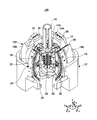
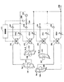
図17は実施例3の多自由度アクチュエータを示す斜視図である。図18は実施例3の制御系を示す系統図である。図19は出力軸16の各動作方向(a)〜(h)に応じた各エアシリンダの動作を模式的に示す図である。尚、図17乃至図19において、上記実施例1、2と同一部分には、同一符号を付してその説明を省略する。
FIG. 17 is a perspective view showing the multi-degree-of-freedom actuator of the third embodiment. FIG. 18 is a system diagram illustrating a control system according to the third embodiment. FIG. 19 is a diagram schematically showing the operation of each air cylinder in accordance with each operation direction (a) to (h) of the
図17に示されるように、実施例3の多自由度アクチュエータ200は、空気圧を駆動力として用いるエア駆動式のものであり、ケーシング12と、出力軸16と、θx方向に出力軸16の基端を揺動可能に支持する第1の揺動機構208と、θy方向に出力軸16の基端を揺動可能に支持する第2の揺動機構220と、第1の揺動機構208を駆動して出力軸16をθx方向に揺動させる第1の駆動部222と、第2の揺動機構220を駆動して出力軸16をθy方向に揺動させる第2の駆動部224とを有する。
As shown in FIG. 17, the multi-degree-of-freedom actuator 200 according to the third embodiment is an air-driven type that uses air pressure as a driving force, and includes a
第1の揺動機構208は、θx方向の揺動をガイドする一対の第1の球面ガイド226と、出力軸16の基端が固定された第1の連結部材228と、第1の連結部材228の両端部に回動可能に連結され第1の球面ガイド226に揺動可能に支持される一対の第1の移動子230とを有する。
The
第2の揺動機構220は、θy方向の揺動をガイドする一対の第2の球面ガイド232と、出力軸16の軸線上で第1の連結部材228と交差するように対向配置され、第1の連結部材228に対して相対的に回動可能に組み合わされた第2の連結部材234と、第2の連結部材234の両端部に回動可能に連結され第2の球面ガイド232に揺動可能に支持される一対の第2の移動子236とを有する。
The
連結部材228,234は、前述した実施例1、2と同様に軸受部38を介して上下方向で回動可能に対向するように設けられている。そのため、連結部材228,234は、駆動部222,224により移動子230,236を揺動動作する際、移動子230,236の揺動動作に応じて相対的に回動することができる。
The connecting
また、連結部材228,234は、夫々両端より側方に突出する円筒形状の軸228b,234bが移動子230,236の内側側面の取付孔に挿入されており、移動子230,236にθx方向、θy方向に回動可能に連結されている。
In addition, the connecting
移動子230,236の外周側は、球面ガイド226,232に対応する球面を有する構成であり、どの方向にも揺動することができる。そして、球面ガイド226,232には、θx方向、θy方向に形成されたエアシリンダ室(圧力室)241〜244が設けられている。このエアシリンダ室(圧力室)241〜244には、移動子230,236と一体に設けられたピストン245〜248が挿入されている。
The outer peripheral side of the
そのため、エアシリンダ室241〜244に供給される空気圧を制御することによりピストン245〜248と共に移動子230,236をθx方向、θy方向に駆動することができる。
Therefore, the moving
図18に示されるように、エアシリンダ室241〜244の空気圧を制御する制御システム250は、圧縮空気を生成する空気圧縮機252と、空気圧縮機252に連通された空気供給管路254と、空気供給管路254に配された圧力制御弁256、逆流防止弁257〜260、4方電磁弁261〜264とから構成されている。また、移動子230,236の移動速度を調整するため、排気管路266には、排気流量を調整する可変絞り268a〜268dが設けられている。従って、エアシリンダ室241〜244に供給される圧縮空気による圧力上昇は、圧力制御弁256によって制御され、エアシリンダ室241〜244から排気される減圧は可変絞り268a〜268dの絞り率によって制御される。
As shown in FIG. 18, the control system 250 that controls the air pressure in the
エアシリンダ室241〜244に挿入されたピストン245〜248は、エアシリンダ室241〜244の上端側と下端側との圧力差によって移動し、圧力が均等にバランスしたとき停止する。そのため、4方電磁弁261〜264を切り替えることにより、エアシリンダ室241〜244に供給される圧縮空気及びエアシリンダ室241〜244から排気される空気量が制御されてピストン245〜248を有する移動子230,236の揺動位置が変更される。
The
4方電磁弁261〜264は、夫々、エアシリンダ室241〜244の上端に連通されたaポートと、エアシリンダ室241〜244の下端に連通されたbポートと、空気供給側に連通されたcポートと、排気管路266に連通されたdポートとを有する。そして、各4方電磁弁261〜264は、制御部270からの制御信号により各ポートの連通を切り替える。例えば、ピストン245〜248を下方に駆動する際は、エアシリンダ室241〜244の上端に圧縮空気を供給すると共に、エアシリンダ室241〜244の下端の空気を排気させる。そのため、4方電磁弁261〜264は、a−c、b−dポートを連通するように切り替わるように制御される。
The four-
また、例えば、ピストン245〜248を上方に駆動する際は、エアシリンダ室241〜244の下端に圧縮空気を供給すると共に、エアシリンダ室241〜244の上端の空気を排気させる。そのため、4方電磁弁261〜264は、a−d、b−cポートを連通するように切り替わるように制御される。
For example, when driving the
また、本実施例では、4個の移動子を個別に駆動する構成であるので、後述するように互いに対向する移動子同士を逆方向に駆動させることになり、4方電磁弁261〜264のうち、4方電磁弁261と263とが互いに逆向きの動作を行なうように切り替えられ、4方電磁弁262と264とが互いに逆向きの動作を行なうように切り替えられる。
Further, in this embodiment, since the four moving elements are individually driven, the moving elements facing each other are driven in opposite directions as will be described later, and the four-
ここで、出力軸16を例えば、45度ずつ8方向(図10を参照)に揺動させる際の制御動作について説明する。各動作方向(a)〜(h)に応じた移動子230,236の動作状態は、前述した図11(A)〜(H)に示すようになる。
Here, a control operation when the
出力軸16の動作方向(a)〜(h)の動作状態は、図19に模式的に示されるように、移動子230,236を駆動するエアシリンダ室241〜244へのエア供給を切り替えることにより実現できる。また、図19において、「降下」とは、エアシリンダ室241〜244にピストン245〜248を降下させるように上端圧力を高くし、下端圧力を下げるように4方電磁弁261〜264を切り替えることを意味し、「上昇」とは、エアシリンダ室241〜244にピストン245〜248を上昇させるように上端圧力を下げ、下端圧力を高くするように4方電磁弁261〜264を切り替えることを意味している。また、図19において、「中間」とは、ピストン245〜248がエアシリンダ室241〜244のストロークの中間位置に移動することを意味している。
The operation state of the
また、出力軸16の揺動角度(鉛直方向の軸線に対する傾斜角度)は、ピストン245〜248の位置を検出する位置センサ(図示せず)から出力された検出信号により得られた揺動位置データに基づいてエアシリンダ室241〜244の上端側と下端側との圧力差を制御することにより、任意の角度に変更することができる。
The swing angle of the output shaft 16 (inclination angle with respect to the vertical axis) is the swing position data obtained from the detection signal output from a position sensor (not shown) that detects the positions of the
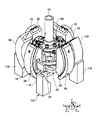
図20は実施例4の多自由度アクチュエータを示す斜視図である。図20に示されるように、実施例4の多自由度アクチュエータ300は、円盤形状の基板301のθx方向、θy方向の角度を調整するためのものであり、外形が八角形に形成されたケーシング302と、基板301が載置されるリング状のテーブル304と、テーブル304をθx方向に揺動可能に支持する第1の揺動機構308と、テーブル304をθy方向に揺動可能に支持する第2の揺動機構310と、第1の揺動機構308を駆動してテーブル304をθx方向に揺動させる第1の駆動部312と、第2の揺動機構310を駆動してテーブル304をθy方向に揺動させる第2の駆動部314とを有する。
FIG. 20 is a perspective view showing the multi-degree-of-freedom actuator of the fourth embodiment. As shown in FIG. 20, the multi-degree-of-
揺動機構308、310は、前述した実施例3の揺動機構208,220と同様な構成であり、駆動部312,314は前述した実施例3の駆動部222,224と同様な構成であるので、その説明は省略する。また、実施例4の制御系も前述した実施例3と同様な構成であるので、その説明は省略する。
The
このように、本発明は、出力軸16を揺動させるだけでなく、円盤形状の基板301のθx方向、θy方向の角度を調整する角度調整機構にも用いることができる。
As described above, the present invention can be used not only for swinging the
本発明の多自由度アクチュエータは、産業上の多くの分野に適用することができ、例えば、産業用ロボットのアーム先端に装着されるロボットハンドの関節機構としても用いることが出来ると共に、円盤状の基板やレンズの位置調整機構、あるいは監視カメラを動作させ撮影方向を調整する機構などにも適用することができる。 The multi-degree-of-freedom actuator of the present invention can be applied to many industrial fields. For example, the multi-degree-of-freedom actuator can be used as a joint mechanism of a robot hand attached to the arm tip of an industrial robot. The present invention can also be applied to a substrate or lens position adjustment mechanism, or a mechanism that operates a surveillance camera to adjust a shooting direction.
また、上記実施例では、駆動部としてサーボモータを用いた構成、リニアモータを用いた構成、空気圧力により作動するエアシリンダを用いた構成のものを一例として示したが、これ以外の駆動手段を用いて各方向の移動子を個別に揺動させる構成としても良いのは勿論である。 In the above embodiment, a configuration using a servo motor as a drive unit, a configuration using a linear motor, and a configuration using an air cylinder operated by air pressure are shown as an example, but other drive means are used. Of course, it is also possible to use a structure in which the moving element in each direction is individually swung.
10,100,200,300 多自由度アクチュエータ
12 ケーシング
16 出力軸
18,208,308 第1の揺動機構
20,220,310 第2の揺動機構
22,102,222,312 第1の駆動部
24,104,224,314 第2の駆動部
26 第1の曲面ガイド
28,228 第1の連結部材
30,230 第1の移動子
32 第2の曲面ガイド
34,234 第2の連結部材
36,236 第2の移動子
38 軸受部
31,37 軸受
40 ころがり軸受
68,70 位置センサ
48,50 サーボモータ
74 制御部
102,104 駆動部
106,108 固定子
114,116 永久磁石
226,232 球面ガイド
241〜244 エアシリンダ室(圧力室)
245〜248 ピストン
256 圧力制御弁
261〜264 4方電磁弁
270 制御部
304 テーブル
10, 100, 200, 300 Multi-degree-of-
245 to 248
Claims (10)
先端が該ケーシングの内部に挿入され、基端が前記ケーシングの開口部より外部に延在する出力軸と、
前記ケーシングの内部に収納され、前記出力軸の軸線と直交する軸回りに前記出力軸の基端を揺動可能に支持する第1の揺動機構と、
前記ケーシングの内部で前記第1の揺動機構と交差するように前記出力軸の軸線上に対向配置され、前記出力軸の軸線と直交する他方向の軸回りに前記出力軸の基端を揺動可能に支持する第2の揺動機構と、
前記第1の揺動機構を駆動して前記出力軸を一方向に揺動させる第1の駆動部と、
前記第2の揺動機構を駆動して前記出力軸を他方向に揺動させる第2の駆動部と、
を有し、
前記第1の揺動機構は、
前記出力軸の基端に対し直交する軸回りの揺動をガイドする第1の曲面ガイドと、
前記出力軸の基端が固定され、前記出力軸の軸線と直交する方向に延在形成された第1の連結部材と、
前記第1の連結部材の両端部に回動可能に連結され、前記第1の曲面ガイドに揺動可能に支持される第1の移動子と、を有し、
前記第2の揺動機構は、
前記出力軸の基端に対し前記第1の曲面ガイドと異なる位置で前記出力軸の基端に対し直交する他の軸回りの揺動をガイドする第2の曲面ガイドと、
前記出力軸の軸線上で前記第1の連結部材と交差するように対向配置され、前記第1の連結部材に対して相対的に回動可能に組み合わされた第2の連結部材と、
前記第2の連結部材の両端部に回動可能に連結され、前記第2の曲面ガイドに揺動可能に支持される第2の移動子と、
を有し、
前記第1の揺動機構と前記第2の揺動機構は、前記第1の駆動部及び前記第2の駆動部の駆動力により前記出力軸が揺動動作する際、前記出力軸の揺動方向に応じて相対的に回動することを特徴とする多自由度アクチュエータ。 A casing,
An output shaft having a distal end inserted into the casing and a proximal end extending outward from the opening of the casing;
A first swing mechanism that is housed in the casing and supports the base end of the output shaft so as to be swingable about an axis orthogonal to the axis of the output shaft;
It is disposed opposite to the axis of the output shaft so as to intersect the first swing mechanism inside the casing, and the base end of the output shaft is swung around an axis in the other direction orthogonal to the axis of the output shaft. A second swing mechanism that is movably supported;
A first drive unit that drives the first swing mechanism to swing the output shaft in one direction;
A second drive unit that drives the second swing mechanism to swing the output shaft in the other direction;
Have
The first swing mechanism is
A first curved surface guide that guides oscillation about an axis orthogonal to the base end of the output shaft;
A first connecting member fixed at a base end of the output shaft and extending in a direction perpendicular to the axis of the output shaft;
A first mover that is pivotally coupled to both ends of the first coupling member and is pivotally supported by the first curved surface guide;
The second swing mechanism is
A second curved surface guide for guiding oscillation around another axis orthogonal to the proximal end of the output shaft at a position different from the first curved surface guide with respect to the proximal end of the output shaft;
A second connecting member that is disposed so as to intersect the first connecting member on the axis of the output shaft, and is combined so as to be rotatable relative to the first connecting member;
A second moving member rotatably connected to both ends of the second connecting member, and supported by the second curved surface guide so as to be swingable;
Have
The first swing mechanism and the second swing mechanism swing the output shaft when the output shaft swings by the driving force of the first drive unit and the second drive unit. A multi-degree-of-freedom actuator characterized by relatively rotating according to a direction.
先端が該ケーシングの内部に挿入され、基端が前記ケーシングの開口部より外部に延在する出力軸と、
前記ケーシングの内部に設けられ、前記出力軸の基端に対し直交する軸回りの揺動をガイドする一対の第1の曲面ガイドと、
前記ケーシングの内部で前記出力軸の基端に対し前記一対の第1の曲面ガイドと異なる位置で前記出力軸の基端に対し直交する他の軸回りの揺動をガイドする一対の第2の曲面ガイドと、
前記出力軸の基端が固定され、前記出力軸の軸線と直交する方向に延在形成された第1の連結部材と、
前記出力軸の軸線上で前記第1の連結部材と交差するように対向配置され、前記第1の連結部材に対して相対的に回動可能に組み合わされた第2の連結部材と、
前記第1の連結部材の両端部に回動可能に連結され、前記一対の第1の曲面ガイドに揺動可能に支持される一対の第1の移動子と、
前記第2の連結部材の両端部に回動可能に連結され、前記一対の第2の曲面ガイドに揺動可能に支持される一対の第2の移動子と、
前記第1の移動子を駆動して前記出力軸を一方向に揺動させる第1の駆動部と、
前記第2の移動子を駆動して前記出力軸を他方向に揺動させる第2の駆動部と、
を有することを特徴とする多自由度アクチュエータ。 A casing,
An output shaft having a distal end inserted into the casing and a proximal end extending outward from the opening of the casing;
A pair of first curved surface guides that are provided inside the casing and guide swinging about an axis orthogonal to the base end of the output shaft;
A pair of second guides for swinging around another axis orthogonal to the base end of the output shaft at a position different from the pair of first curved surface guides relative to the base end of the output shaft inside the casing. Curved guide,
A first connecting member fixed at a base end of the output shaft and extending in a direction perpendicular to the axis of the output shaft;
A second connecting member that is disposed so as to intersect the first connecting member on the axis of the output shaft, and is combined so as to be rotatable relative to the first connecting member;
A pair of first movers that are pivotably coupled to both ends of the first coupling member and are pivotally supported by the pair of first curved surface guides;
A pair of second movers that are pivotally coupled to both ends of the second coupling member and are pivotally supported by the pair of second curved surface guides;
A first drive unit that drives the first moving element to swing the output shaft in one direction;
A second drive unit that drives the second moving element to swing the output shaft in the other direction;
A multi-degree-of-freedom actuator comprising:
該ケーシングの内部に挿入されたテーブルと、
前記ケーシングの軸線と直交する一方向の軸回りに前記テーブルを揺動可能に支持する第1の揺動機構と、
前記第1の揺動機構と交差するように前記テーブルの軸線上に対向配置され、前記テーブルの軸線と直交する他方向の軸回りに前記テーブルを揺動可能に支持する第2の揺動機構と、
前記一方向の軸回りに湾曲した第1のシリンダ室と、作動流体の圧力により前記第1のシリンダ室に沿って回動する第1のピストンとを有し、前記第1のピストンの回動と共に前記第1の揺動機構を駆動して前記テーブルを一方向に揺動させる第1の駆動部と、
前記他方向の軸回りに湾曲した第2のシリンダ室と、作動流体の圧力により該第2のシリンダ室に沿って回動する第2のピストンとを有し、前記第2のピストンの回動と共に前記第2の揺動機構を駆動して前記テーブルを他方向に揺動させる第2の駆動部と、
を有し、
前記第1の揺動機構と前記第2の揺動機構は、前記第1の駆動部及び前記第2の駆動部の駆動力により前記テーブルが揺動動作する際、前記テーブルの揺動方向に応じて相対的に回動することを特徴とする多自由度アクチュエータ。 A casing,
A table inserted inside the casing;
A first swing mechanism that swingably supports the table about an axis in one direction perpendicular to the axis of the casing;
A second swing mechanism that is disposed opposite the axis of the table so as to intersect the first swing mechanism and supports the table so as to be swingable about an axis in another direction orthogonal to the axis of the table. When,
A first cylinder chamber that is curved around the one-direction axis; and a first piston that rotates along the first cylinder chamber by a pressure of a working fluid, and the rotation of the first piston. And a first drive unit that drives the first swing mechanism to swing the table in one direction;
A second cylinder chamber curved around the axis in the other direction, and a second piston that rotates along the second cylinder chamber by the pressure of the working fluid, and the rotation of the second piston And a second drive unit that drives the second swing mechanism to swing the table in the other direction;
Have
The first swing mechanism and the second swing mechanism are arranged in a swing direction of the table when the table swings by the driving force of the first drive unit and the second drive unit. A multi-degree-of-freedom actuator characterized by relatively rotating in response.
Priority Applications (1)
| Application Number | Priority Date | Filing Date | Title |
|---|---|---|---|
| JP2005280681A JP4641237B2 (en) | 2005-09-27 | 2005-09-27 | Multi-degree-of-freedom actuator |
Applications Claiming Priority (1)
| Application Number | Priority Date | Filing Date | Title |
|---|---|---|---|
| JP2005280681A JP4641237B2 (en) | 2005-09-27 | 2005-09-27 | Multi-degree-of-freedom actuator |
Publications (2)
| Publication Number | Publication Date |
|---|---|
| JP2007097267A JP2007097267A (en) | 2007-04-12 |
| JP4641237B2 true JP4641237B2 (en) | 2011-03-02 |
Family
ID=37982281
Family Applications (1)
| Application Number | Title | Priority Date | Filing Date |
|---|---|---|---|
| JP2005280681A Expired - Fee Related JP4641237B2 (en) | 2005-09-27 | 2005-09-27 | Multi-degree-of-freedom actuator |
Country Status (1)
| Country | Link |
|---|---|
| JP (1) | JP4641237B2 (en) |
Families Citing this family (5)
| Publication number | Priority date | Publication date | Assignee | Title |
|---|---|---|---|---|
| KR101419831B1 (en) * | 2012-02-17 | 2014-07-16 | 한양대학교 산학협력단 | Driving apparatus having multi-degrees of freedom |
| CN108886316A (en) * | 2016-03-30 | 2018-11-23 | 松下知识产权经营株式会社 | Actuator and coil unit |
| CN109983677A (en) * | 2016-11-16 | 2019-07-05 | 松下知识产权经营株式会社 | Actuator and camera apparatus |
| JPWO2019017286A1 (en) * | 2017-07-18 | 2020-07-30 | パナソニックIpマネジメント株式会社 | Actuator and camera device |
| CN110535285A (en) * | 2019-08-05 | 2019-12-03 | 河北科技大学 | Multi-freedom electric motor |
Family Cites Families (7)
| Publication number | Priority date | Publication date | Assignee | Title |
|---|---|---|---|---|
| JPH0685630B2 (en) * | 1984-03-28 | 1994-10-26 | 工業技術院長 | Three-dimensional motor |
| JPH0714269B2 (en) * | 1986-03-22 | 1995-02-15 | 日本電信電話株式会社 | Spherical motor |
| JPH0516186U (en) * | 1991-08-22 | 1993-03-02 | 三菱重工業株式会社 | Multi-DOF actuator |
| JPH06284673A (en) * | 1993-03-24 | 1994-10-07 | Iwao Shibata | Multi-dimensional operation actuator |
| JP2003324936A (en) * | 2002-04-25 | 2003-11-14 | Matsushita Electric Ind Co Ltd | Spherical motor |
| JP2004329726A (en) * | 2003-05-12 | 2004-11-25 | Hitachi Ltd | Surgical equipment |
| JP2005033989A (en) * | 2003-06-20 | 2005-02-03 | Victor Co Of Japan Ltd | Multiple-degree-of-freedoms oscillatory actuator |
-
2005
- 2005-09-27 JP JP2005280681A patent/JP4641237B2/en not_active Expired - Fee Related
Also Published As
| Publication number | Publication date |
|---|---|
| JP2007097267A (en) | 2007-04-12 |
Similar Documents
| Publication | Publication Date | Title |
|---|---|---|
| US7281447B2 (en) | Articulated mechanism comprising a cable reduction gear for use in a robot arm | |
| JP3413730B2 (en) | Horizontal articulated robot | |
| KR102838341B1 (en) | Device for robot-assisted machining of surfaces | |
| JP7163744B2 (en) | Robot drive mechanism and robot | |
| US20110113915A1 (en) | Parallel robot | |
| JP2014124742A (en) | Arm-driving device | |
| JP2010532265A (en) | High dynamic laser processing machine | |
| JP4641237B2 (en) | Multi-degree-of-freedom actuator | |
| JP6110620B2 (en) | Parallel link robot | |
| JP2016060023A (en) | Rotation drive mechanism in robot | |
| JP5171119B2 (en) | Reciprocating mechanism and pick and place device | |
| JP6921839B2 (en) | Closed center pressure flow control valve | |
| JP6799445B2 (en) | Robot joint structure | |
| KR100816360B1 (en) | Anti-moment static-pressure gas bearing mechanism | |
| CN120269604A (en) | Customized multi-motor driving type robot joint and motor double-ring control method | |
| KR20050054821A (en) | A robot | |
| JP6043561B2 (en) | Parallel link robot | |
| JP2020192625A (en) | Parallel link robot | |
| JP2547512B2 (en) | Industrial robot | |
| JP2014065122A (en) | Parallel link robot | |
| JP2760581B2 (en) | Positioning device | |
| JP6783474B2 (en) | A table drive device and a work system equipped with the table drive device | |
| JPH0829513B2 (en) | Industrial robots | |
| JP6062305B2 (en) | Actuator unit | |
| JP4740605B2 (en) | Gas control rotary movement device and gas control actuator |
Legal Events
| Date | Code | Title | Description |
|---|---|---|---|
| A621 | Written request for application examination |
Free format text: JAPANESE INTERMEDIATE CODE: A621 Effective date: 20071016 |
|
| A977 | Report on retrieval |
Free format text: JAPANESE INTERMEDIATE CODE: A971007 Effective date: 20100401 |
|
| A131 | Notification of reasons for refusal |
Free format text: JAPANESE INTERMEDIATE CODE: A131 Effective date: 20100907 |
|
| A521 | Request for written amendment filed |
Free format text: JAPANESE INTERMEDIATE CODE: A523 Effective date: 20101102 |
|
| TRDD | Decision of grant or rejection written | ||
| A01 | Written decision to grant a patent or to grant a registration (utility model) |
Free format text: JAPANESE INTERMEDIATE CODE: A01 Effective date: 20101124 |
|
| A01 | Written decision to grant a patent or to grant a registration (utility model) |
Free format text: JAPANESE INTERMEDIATE CODE: A01 |
|
| A61 | First payment of annual fees (during grant procedure) |
Free format text: JAPANESE INTERMEDIATE CODE: A61 Effective date: 20101126 |
|
| R150 | Certificate of patent or registration of utility model |
Free format text: JAPANESE INTERMEDIATE CODE: R150 |
|
| FPAY | Renewal fee payment (event date is renewal date of database) |
Free format text: PAYMENT UNTIL: 20131210 Year of fee payment: 3 |
|
| LAPS | Cancellation because of no payment of annual fees |