JP4640775B2 - Heat fixing device and image forming apparatus - Google Patents
Heat fixing device and image forming apparatus Download PDFInfo
- Publication number
- JP4640775B2 JP4640775B2 JP2004341227A JP2004341227A JP4640775B2 JP 4640775 B2 JP4640775 B2 JP 4640775B2 JP 2004341227 A JP2004341227 A JP 2004341227A JP 2004341227 A JP2004341227 A JP 2004341227A JP 4640775 B2 JP4640775 B2 JP 4640775B2
- Authority
- JP
- Japan
- Prior art keywords
- heater
- heat
- holder
- longitudinal direction
- heat fixing
- Prior art date
- Legal status (The legal status is an assumption and is not a legal conclusion. Google has not performed a legal analysis and makes no representation as to the accuracy of the status listed.)
- Expired - Fee Related
Links
Images


Classifications
-
- G—PHYSICS
- G03—PHOTOGRAPHY; CINEMATOGRAPHY; ANALOGOUS TECHNIQUES USING WAVES OTHER THAN OPTICAL WAVES; ELECTROGRAPHY; HOLOGRAPHY
- G03G—ELECTROGRAPHY; ELECTROPHOTOGRAPHY; MAGNETOGRAPHY
- G03G15/00—Apparatus for electrographic processes using a charge pattern
- G03G15/20—Apparatus for electrographic processes using a charge pattern for fixing, e.g. by using heat
- G03G15/2003—Apparatus for electrographic processes using a charge pattern for fixing, e.g. by using heat using heat
- G03G15/2014—Apparatus for electrographic processes using a charge pattern for fixing, e.g. by using heat using heat using contact heat
- G03G15/2053—Structural details of heat elements, e.g. structure of roller or belt, eddy current, induction heating
-
- G—PHYSICS
- G03—PHOTOGRAPHY; CINEMATOGRAPHY; ANALOGOUS TECHNIQUES USING WAVES OTHER THAN OPTICAL WAVES; ELECTROGRAPHY; HOLOGRAPHY
- G03G—ELECTROGRAPHY; ELECTROPHOTOGRAPHY; MAGNETOGRAPHY
- G03G15/00—Apparatus for electrographic processes using a charge pattern
- G03G15/20—Apparatus for electrographic processes using a charge pattern for fixing, e.g. by using heat
- G03G15/2003—Apparatus for electrographic processes using a charge pattern for fixing, e.g. by using heat using heat
- G03G15/2014—Apparatus for electrographic processes using a charge pattern for fixing, e.g. by using heat using heat using contact heat
- G03G15/2039—Apparatus for electrographic processes using a charge pattern for fixing, e.g. by using heat using heat using contact heat with means for controlling the fixing temperature
- G03G15/2042—Apparatus for electrographic processes using a charge pattern for fixing, e.g. by using heat using heat using contact heat with means for controlling the fixing temperature specially for the axial heat partition
Landscapes
- Physics & Mathematics (AREA)
- General Physics & Mathematics (AREA)
- Fixing For Electrophotography (AREA)
Abstract
Description
本発明は、被加熱体を加熱するための加熱体、特に電子写真装置においてトナー像を記録材(転写材)に溶融固着させるための加熱装置および画像形成装置に関するものである。 The present invention relates to a heating body for heating a heated body, and more particularly to a heating apparatus and an image forming apparatus for melting and fixing a toner image to a recording material (transfer material) in an electrophotographic apparatus.
例えば、プリンタ、複写機、記録装置、ファクシミリ等の画像記録装置は加熱定着装置を用いるものがある。この加熱定着装置は、電子写真等による記録部にて記録材に目的の画像情報に対応した未定着画像を形成担持させ、これを加熱定着させるための装置であり、所定の温度に維持された加熱ローラと、弾性層を有して前記加熱ローラに圧接する加圧ローラによって記録材を挟持搬送しつつ加熱する熱ローラ方式が多用されている。しかし、熱ローラ方式は、熱ローラ表面が定着温度に達するまでのウォームアップ時間を長く必要とする等の問題がある。 For example, some image recording apparatuses such as a printer, a copying machine, a recording apparatus, and a facsimile use a heat fixing apparatus. This heat fixing device is a device for forming and carrying an unfixed image corresponding to target image information on a recording material in a recording section by electrophotography or the like, and heat fixing this, and maintained at a predetermined temperature. A heat roller system in which a recording material is heated while being sandwiched and conveyed by a heating roller and a pressure roller having an elastic layer and being in pressure contact with the heating roller is widely used. However, the heat roller system has problems such as requiring a long warm-up time until the surface of the heat roller reaches the fixing temperature.
そこで、これに代わる加熱定着方式として、熱伝達効率が高く、装置の立ち上がりも速い方式として、固定支持された低熱容量のサーマルヒータと、このヒータに対して摺動する薄膜のフィルムを用いたフィルム加熱方式の加熱装置が提案されている(特許文献1、2、3等参照)。
Therefore, as an alternative heating and fixing method, as a method of high heat transfer efficiency and quick start-up of the device, a film using a fixed and supported low-heat capacity thermal heater and a thin film that slides against this heater Heating-type heating devices have been proposed (see
図6(A)にフィルム加熱方式の像加熱装置(加熱定着装置)の一例の要部の横断面模型図を示した。図6(B)はヒータの一部切欠き平面図、図6(C)はヒータホルダのヒータ嵌め込み溝部分の平面図である。 FIG. 6A shows a schematic cross-sectional view of an essential part of an example of a film heating type image heating apparatus (heating fixing apparatus). FIG. 6B is a partially cutaway plan view of the heater, and FIG. 6C is a plan view of the heater insertion groove portion of the heater holder.
セラミックヒータ1は、加熱体であり、剛性および断熱性を有するヒータホルダ2において、このヒータホルダの下面に長手方向に沿って形成具備させたヒータ嵌め込み溝2a内に嵌め込んで固定支持させてある。
The
フィルム3は耐熱性の定着フィルムである。このフィルム3は、熱容量を小さくしてクイックスタート性を向上させるために、通常、膜厚100μm以下の、耐熱性、離型性、耐久性を兼ね備えたポリイミド等のフィルム表面にPTFE、PFA、FEPを離型層としてコーティングした複合フィルムで構成されている。
加圧ローラ4は、フィルム3を挟んでヒータ1の下向き面とニップ部N(加熱ニップ部、定着ニップ部)を形成する加圧部材としての耐熱ゴムからなる弾性ローラである。
The pressure roller 4 is an elastic roller made of heat-resistant rubber as a pressure member that forms a downward surface of the
この加圧ローラ4でフィルム3をセラミックヒータ1の下向き面に密着させて矢印方向aに摺動搬送させ、ニップ部Nのフィルム3と加圧ローラ4との間に被加熱材としての画像定着すべき用紙等の記録材Pを導入してフィルム3と一緒に記録材Pを挟持搬送させる。これによりセラミックヒータ1の熱をフィルム3を介して記録材に付与して記録材P上の未定着顕画像(トナー画像)tを記録材面に加熱定着させる。ニップ部Nを通った記録材部分はフィルム3の面から順次に曲率分離して搬送される。
With this pressure roller 4, the
加熱体としてのセラミックヒータ1は、次の要素等から構成され、全体に低熱容量の略平板状の部材である。
a.フィルム3または記録材Pのニップ部Nにおける移動方向aに対して直交する方向(図6(A)面に垂直方向)を長手とする横長かつ薄肉で、耐熱性・低熱容量・良熱伝導性・電気絶縁性を有する平板状のヒータ基板1a
b.ヒータ基板1aの一面(表面)側に基板長手方向に沿って細帯状に形成され、通電により発熱する通電発熱抵抗体1b
c.通電発熱抵抗体1bを形成具備させたヒータ基板1aの一面(表面)側をオーバーコートした耐熱性・絶縁性を有する表面保護層1c
d.ヒータ基板1aの他面(裏面)側に設けた温度検知素子1d
The
a. A horizontally long and thin wall having a direction perpendicular to the moving direction a in the nip N of the
b. An
c. Heat-resistant / insulating surface
d.
ヒータ基板1aは、本実施の形態では例えば、長さ240mm、幅10mm、厚さ1mmのアルミナ(酸化アルミニウム、Al2 O3 )からなるセラミック材基板である。
In the present embodiment, the
通電発熱抵抗体1bは、例えば、銀パラジウム(Ag/Pb)、Ta2 N等の電気抵抗材料ペースト(抵抗ペースト)を例えば厚み10μm、幅1〜3mmの細帯状にヒータ基板表面に基板長手方向に沿ってスクリーン印刷等によりパターン塗工し焼成することで形成したものである。通電電極1eおよび1eはこの通電発熱抵抗体1bの両端部に導通させてヒータ基板表面に形成された電極である。この通電電極1e,1eはAgペーストをスクリーン印刷等により塗工し焼成することで形成したものである。
The
表面保護層1cは、例えば、厚さ10μm程度の耐熱性ガラス層である。温度検知素子1dは、例えば、チップ型あるいは印刷薄膜タイプのサーミスタである。
The surface
このヒータ1を、ヒータホルダ2においてこのヒータホルダの下面に長手方向に沿って形成したヒータ嵌め込み溝2a内に、抵抗発熱抵抗体1bおよび表面保護層1cを形成したヒータ基板1aの表面側を下向きに露呈させて、嵌め込んで固定支持させてある。ヒータ嵌め込み溝2a内に嵌め込んだヒータ1が溝2a内のヒータ当接面2bで直接当接支持される構成となっている。溝2aの底面中央部には、いわゆるザグリによる空隙2cを設けることで、ヒータ裏面からヒータホルダ2側への熱の逃げを抑制し、ニップ部側の加熱効率を向上させるような構成となっている。
The
ヒータ1は、不図示の給電回路による通電発熱抵抗体1bに対する給電により該通電発熱抵抗体が長手全長にわたって発熱することで迅速に昇温する。この昇温は温度検知素子1dで検知される。その検知温度情報は不図示の温度制御回路に入力されて、ヒータ1の温度が所定の温度に維持(温調)されるように通電発熱抵抗体1bへの通電が制御される。また、ヒータ1は、長手方向に均等に圧力が加わるように、ヒータホルダ2の長手方向において、クラウン形状をした連続的な面で受けるようになっている。
上述の従来技術では、前述したように定着側の加熱効率を向上させるようにヒータホルダ2の当接支持される底部にザグリによる空隙2cを設けているが、ヒータ1からヒータホルダ2への熱の逃げる割合が部分的に異なってしまい、実際の使用時でのヒータ1の長手方向の温度分布が必ずしも均一にならないという問題があった。
In the above-described prior art, as described above, the
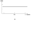
また、図2に示すように、ヒータ1自体の発熱量を均一にしてあり、ヒータ1をヒータホルダ2に当接支持させた状態のヒータ1長さ方向の温度分布は図7に示す如く、中央部よりも端部は低下してしまう。これは、端部の熱の移動が一方向からのみしかないためと、端部の通電発熱抵抗体以外の電極部等に熱が逃げてしまうこととによる。そのため、端部の温度が不足して定着できずにいわゆるトナー剥がれが起きるという問題があった。また、幅の狭いA5サイズの用紙を連続して50枚通紙した場合には、図8に示すように、非通紙部昇温は242℃と高くなり、中央部との差は約60℃と大きくなる。
Further, as shown in FIG. 2, the heat distribution of the
上記のようなトナー剥がれの発生を防止するためにヒータホルダ2のヒータ当接支持部の空隙2cを大きくすると、ヒータ1からヒータホルダ2への熱の逃げる割合が減少するため、幅の狭い記録材を通紙した場合に記録材が通過しない部分の非通紙部昇温が急激に発生してしまう。また、ヒータ1内部に生じる熱ストレスによって割れが発生するおそれがある。更には、ヒータホルダ2としてヒータ取付座面の強度が低下して、加圧時に、ヒータを支えることができなくなる、という問題があった。
If the
そこで、本発明は、主に小サイズ紙を通紙した時の中央部と端部との温度差を緩和し、小サイズ紙の定着性の確保と非通紙部昇温を抑えることを目的とする。 Therefore, the present invention aims to alleviate the temperature difference between the center and the edge when small-size paper is passed, and to ensure the fixing property of small-size paper and suppress the temperature rise of the non-sheet-passing portion. And
また、本発明は、記録材の特定位置における温度不足による定着不良を防止し、且つ記録材幅が狭いときに起こる非通紙部昇温を抑えることができる加熱定着装置および画像形成装置を提供することを目的とする。 The present invention also provides a heat fixing device and an image forming apparatus that can prevent fixing failure due to insufficient temperature at a specific position of a recording material and suppress non-sheet passing portion temperature rise that occurs when the recording material width is narrow. The purpose is to do.
本発明による加熱定着装置は、記録材上に形成担持された未定着画像を加熱定着させるための加熱定着装置であって、発熱体を有するヒータと、このヒータを支持するヒータホルダとを備え、ヒータのヒータホルダに対する接触率を、ヒータの長手方向両端部において中央部より大きくしたことを特徴とする。 A heat fixing apparatus according to the present invention is a heat fixing apparatus for heat fixing an unfixed image formed and supported on a recording material, and includes a heater having a heating element and a heater holder that supports the heater. The contact ratio of the heater with respect to the heater holder is made larger than the central portion at both ends in the longitudinal direction of the heater.
より具体的には、接触率を変えるために、ヒータの少なくとも一面において、ヒータの長手方向両端部においてヒータとヒータホルダとが接触し、中央部においてヒータとヒータホルダとの間に空隙が形成されるようにする。 More specifically, in order to change the contact rate, the heater and the heater holder are in contact with each other at both ends in the longitudinal direction of the heater on at least one surface of the heater, and a gap is formed between the heater and the heater holder in the central portion. To.
接触率を変える代わりに、ヒータの長手方向両端部において、ヒータホルダの厚さを、中央部より大きくするようにしてもよい。 Instead of changing the contact rate, the thickness of the heater holder may be made larger than the central portion at both ends in the longitudinal direction of the heater.
このような構成によりヒータホルダに移行する熱量を局所的に増減させることができ、ヒータ自体の熱を効率よく定着ニップ側に伝えることで、記録材幅が狭く且つ定着性が比較的劣る例えばハガキや封筒などの小サイズ紙を通紙した時の温度不足による定着できずに起こるトナー剥がれを防止することができる。 With such a configuration, the amount of heat transferred to the heater holder can be locally increased or decreased, and by efficiently transferring the heat of the heater itself to the fixing nip side, the recording material width is narrow and the fixing property is relatively inferior. It is possible to prevent the toner from peeling off due to insufficient temperature when passing through a small size paper such as an envelope.
本発明による他の加熱定着装置は、記録材上に形成担持された未定着画像を加熱定着させるための加熱定着装置であって、発熱体を有するヒータと、このヒータを支持するホルダとを備え、前記ヒータの長手方向における単位長あたりの発熱量の分布を不均一に設定し、ヒータのホルダに対する接触率を、単位長あたりの発熱量が少ない位置において、発熱量の多い位置よりも小さくしたことを特徴とする。 Another heat fixing apparatus according to the present invention is a heat fixing apparatus for heat fixing an unfixed image formed and supported on a recording material, and includes a heater having a heating element and a holder for supporting the heater. The distribution of the heat generation amount per unit length in the longitudinal direction of the heater is set non-uniformly, and the contact ratio of the heater with the holder is made smaller at the position where the heat generation amount per unit length is small than at the position where the heat generation amount is large. It is characterized by that.
この構成では、ヒータ単体の発熱分布を積極的に不均一とする。特に、ヒータの長手方向における両端部の発熱量が中央部の発熱量より高くなるように前記発熱体の発熱量分布を設定する。併せて、ヒータのホルダに対する接触率を発熱量の分布に応じて変える。すなわち、ヒータのホルダに対する接触率を、単位長あたりの発熱量が少ない位置において、発熱量の多い位置よりも小さくする。具体的には、ヒータの少なくとも一面において、前記単位長あたりの発熱量が多い位置ではヒータとホルダとが接触し、前記発熱量が少ない位置ではヒータとホルダとの間に空隙が形成される。 In this configuration, the heat distribution of the heater alone is positively made uneven. In particular, the calorific value distribution of the heating element is set so that the calorific value at both ends in the longitudinal direction of the heater is higher than the calorific value at the center. At the same time, the contact ratio of the heater to the holder is changed according to the distribution of heat generation. That is, the contact rate of the heater with respect to the holder is made smaller at a position where the heat generation amount per unit length is small than at a position where the heat generation amount is large. Specifically, on at least one surface of the heater, the heater and the holder are in contact with each other at a position where the calorific value per unit length is large, and a gap is formed between the heater and the holder at a position where the calorific value is small.
このような構成により、トナー剥がれのような温度不足による定着不良を発生する位置の温度を高めて、定着不良の発生を防止することができる。これと共に、そのような発熱量の多い位置が幅の狭い記録材の連続で通紙時の非通紙位置となっても、その位置でのヒータとホルダの接触率を高めることにより、ホルダへの熱の放散が良好となるので、非通紙位置での過昇温が防止される。 With such a configuration, it is possible to prevent the occurrence of fixing failure by increasing the temperature at a position where fixing failure due to temperature shortage such as toner peeling occurs. At the same time, even if such a position with a large amount of heat generation becomes a non-sheet passing position during continuous feeding of a narrow recording material, by increasing the contact rate between the heater and the holder at that position, Therefore, the excessive temperature rise at the non-sheet passing position is prevented.
本発明による他の加熱定着装置は、記録材上に形成担持された未定着画像を加熱定着させるための加熱定着装置であって、発熱体を有するヒータと、このヒータを支持するホルダとを備え、前記ヒータの長手方向における単位長あたりの発熱量の分布を不均一に設定し、前記ホルダの長手方向単位長当たりの体積を、単位長あたりの発熱量が多い位置において、発熱量の少ない位置よりも大きくしたことを特徴とする。 Another heat fixing apparatus according to the present invention is a heat fixing apparatus for heat fixing an unfixed image formed and supported on a recording material, and includes a heater having a heating element and a holder for supporting the heater. The distribution of the heat generation amount per unit length in the longitudinal direction of the heater is set non-uniformly, and the volume per unit length in the longitudinal direction of the holder is set at a position where the heat generation amount is small at a position where the heat generation amount per unit length is large. It is characterized by being larger than.
具体的には、例えば、前記単位長あたりの発熱量が少ない位置において、ホルダの厚さを、前記発熱量の多い位置に比べて小さくすることができる。この構成によっても上記と同様の作用が得られる。 Specifically, for example, the thickness of the holder can be reduced at a position where the heat generation amount per unit length is small compared to the position where the heat generation amount is large. With this configuration, the same operation as described above can be obtained.
本発明による加熱定着装置は、他の見地によれば、記録材上に形成担持された未定着画像を加熱定着させるための加熱定着装置であって、発熱体を有するヒータと、このヒータを支持するホルダとを備え、ヒータの長手方向における両端部の発熱量が中央部の発熱量より高くなるように前記発熱体の発熱量分布を設定し、ヒータの発する熱が両端部においてホルダ側へ逃げやすく中央部においてホルダ側へ逃げにくくしたことを特徴とするものである。 According to another aspect, the heat fixing apparatus according to the present invention is a heat fixing apparatus for heat fixing an unfixed image formed and supported on a recording material, and includes a heater having a heating element and the heater. And a heating value distribution of the heating element is set so that the heating value at both ends in the longitudinal direction of the heater is higher than the heating value at the center, and the heat generated by the heater escapes to the holder side at both ends. It is easy to escape to the holder side in the central part.
本発明は、前記ヒータに対して摺動する薄膜のフィルムを用いたフィルム加熱方式を採用したものに適用して好適である。 The present invention is suitable for application to a film heating method using a thin film that slides against the heater.
本発明によれば、記録材上に形成担持された未定着画像を加熱定着させるための加熱定着装置において、ヒータからヒータホルダに移行する熱量を局所的に減らすことで、中央部分でヒータ自体の熱を効率よくニップN側に伝えることができ、記録材幅が狭く、且つ厚紙等の時の温度不足による定着できずに起こるトナー剥がれを防止する加熱定着装置を提供することが可能となった。 According to the present invention, in a heat fixing device for heat fixing an unfixed image formed and supported on a recording material, the amount of heat transferred from the heater to the heater holder is locally reduced, so that the heat of the heater itself at the central portion. Can be efficiently transmitted to the nip N side, and it is possible to provide a heating and fixing device that prevents the toner from peeling off due to the narrow recording material width and the inability to fix due to insufficient temperature at the time of thick paper or the like.
また、ヒータの長手方向における単位長あたりの発熱量の分布を積極的に不均一に設定することにより、従来温度不足となっていた位置の定着不良をより効果的に防止することができる。 Further, by actively setting the distribution of the amount of heat generated per unit length in the longitudinal direction of the heater to be non-uniform, it is possible to more effectively prevent fixing defects at positions where the temperature has been insufficient.
これと共に、単位長あたりの発熱量の多い位置(例えば両端部)においてヒータの発する熱がホルダ側へ逃げやすく、かつ、単位長あたりの発熱量の少ない位置(例えば中央部)においてホルダ側へ逃げにくくすることにより、幅の狭い記録材を通紙するときに起こる非通紙部での過昇温を抑えることが可能となった。 At the same time, the heat generated by the heater easily escapes to the holder side at a position where the heat generation amount per unit length is large (for example, both ends), and escapes to the holder side at a position where the heat generation amount per unit length is small (for example, the center portion). By making it difficult, it becomes possible to suppress the excessive temperature rise in the non-sheet passing portion that occurs when the narrow recording material is passed.
以下、本発明の好適な実施の形態について詳細に説明する。 Hereinafter, preferred embodiments of the present invention will be described in detail.
<第1の実施の形態>
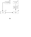
まず、図9に、本実施の形態に係る、画像形成装置に用いられる加熱定着装置におけるヒータの温度制御装置の概略構成を示す。この構成自体は従来のものと同じである。すなわち、ヒータ1上に設けられた温度検知素子(ここではサーミスタ)1dの出力をA/D変換器12によりA/D変換してCPU10に取り込む。CPU10は、その情報をもとにトライアック11を介してヒータ1に通電するAC電圧に対して位相制御、波数制御等を行うことにより、加熱体通電電力を制御する。このような構成は、後述する他の実施の形態についても同じである。
<First Embodiment>
First, FIG. 9 shows a schematic configuration of a heater temperature control device in the heat fixing device used in the image forming apparatus according to the present embodiment. This configuration itself is the same as the conventional one. That is, the output of the temperature detection element (here, the thermistor) 1d provided on the
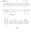
図1(b)に、本発明の第1の実施の形態に係る、通電により発熱する発熱体を有するヒータ1の平面図を示し、図1(a)にヒータホルダ2のヒータ嵌め込み溝部分の平面図を示す。また、図1(c)にヒータホルダ2の正面図を示す。これらの加熱定着装置の構造は図6に示した従来技術と同様である。ヒータ基板は1.0mm厚のものであるが、これに限るものではない。
FIG. 1B shows a plan view of the
同図のヒータ1の通電発熱抵抗体1bの全長は220mmで、軸方向の長さXは6.5mmにしてある。位置の単位長さあたりの抵抗値Roとしている。ヒータ1自体の発熱量分布は、図2に示したように均一にしている。
The total length of the
ヒータホルダ2は、PPS、液晶ポリマー、フェノール樹脂等の耐熱樹脂で成形により作られている。ヒータホルダ2にはヒータ1を嵌め込むようにヒータ取付座面が形成されており、取付座面の形状はヒータの長手方向端部位置はヒータ側にβの如く突出しており、中央部はヒータホルダ2とヒータ1との間に空隙αが存在するようにしている。図1(c)から判るように、ヒータホルダの長手方向の複数箇所には搬送されるフィルム3を規制するリブ部2fが形成されている。
The
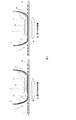
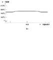
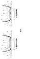
図3(a)および(b)に、それぞれ、ヒータホルダ2にヒータ1を当接支持させた長さ方向の中央と端部と横断面図を示した。図3(a)では、長さ方向中央部ヒータホルダ2とヒータ1との空隙α部が存在し、図3(b)では、長さ方向端部でヒータホルダ2はヒータ1の側面に密着当接している。この状態でヒータ1の通電加熱抵抗体1bに通電させた時の温度分布を、図4に示す。各長さ方向位置の温度は、中央部195℃であり、端部193℃となっている。ヒータ1を支持するホルダ2の単位体積あたりの接触率は、ヒータ基材長さ方向で中央部より端部の方を大きくすることで、中央部の熱のヒータホルダ2への放熱効果を抑制し、端部は逆に放熱効果を高めている。
3 (a) and 3 (b) show a center, an end portion, and a cross-sectional view in the length direction in which the
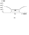
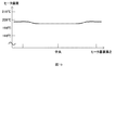
図5に、このような構成で幅の狭いA5サイズの用紙(記録材)を連続50枚通紙した場合の温度分布を示す。図5の例では、用紙の通過していない箇所の非通紙部昇温の最高到達温度は215℃であり、図8の従来の構成の最高到達温度である242℃と比較しても分かるように、27℃弱の温度差がある。すなわち、本実施の形態の構成では、非通紙部昇温を低い温度に抑えることができた。この非通紙部昇温に対してヒータ1の熱をヒータホルダ2に積極的に逃がす放熱効果を効率的にすることができ、熱ストレスが少なくなり、ヒータ1が割れにくくなった。また、中央部と端部との温度差を緩和し、小サイズ紙の定着性の確保と非通紙部昇温を抑えることができた。
FIG. 5 shows a temperature distribution when 50 sheets of A5 size paper (recording material) having a narrow width are continuously fed with such a configuration. In the example of FIG. 5, the maximum temperature of the non-sheet-passing portion temperature rise at the portion where the paper does not pass is 215 ° C., which can be seen by comparing with the maximum temperature of 242 ° C. of the conventional configuration of FIG. As such, there is a temperature difference of a little less than 27 ° C. That is, in the configuration of the present embodiment, the non-sheet passing portion temperature rise can be suppressed to a low temperature. The heat radiation effect of actively releasing the heat of the
<第2の実施の形態>
次に、本発明の第2の実施の形態について説明する。図10に第2の実施の形態における、図1に対応する図を示す。ヒータ1については前述の第1の実施の形態と同様のヒータ1であるため説明は省略する。ヒータ基板は1.0mm厚のものであるが、これに限るものではない。
<Second Embodiment>
Next, a second embodiment of the present invention will be described. FIG. 10 shows a diagram corresponding to FIG. 1 in the second embodiment. Since the
第1の実施の形態ではヒータホルダ2とヒータ1との接触率を変化させたが、これに対し、第2の実施の形態では、図10(a)から分かるように、ヒータホルダ2のヒータ当接面部はヒータ1の長さ方向及び幅方向での形状は同様である。このように、ヒータホルダ2とヒータ1との長さ方向での接触面積は均一にしている。しかし、図10(c)およびヒータホルダ2の長手方向に垂直な断面図である図11(a)(b)から分かるように、ヒータホルダ2の断面形状をヒータ1の端部と中央部とで異ならせている。すなわち、ヒータホルダ2のヒータ1支持部の肉厚は、中央部はZ1(例えば3.5mm)であるのに対し、温度の高くなる端部はZ1より大きいZ2(例えば6.0mm)としている。従って、ヒータホルダ2の長さ方向単位あたりの体積が、ヒータ1の温度が高くなる端部は大きく、中央部は小さい。よって、中央部の熱はヒータホルダ2の体積が極力少なくされているため、熱がヒータホルダ2側に逃げる割合を減らることができ、ヒータ1自体の発熱量が効率よくニップN側へ伝えられる。他方、端部はヒータガイド2の体積が大きいことで、放熱効果を高めることができ、ヒータ1自体の発熱量は、ニップN側とヒータホルダ2側の両方に分散する。よって、端部近傍のニップN側の温度は抑えられることとなった。
In the first embodiment, the contact ratio between the
前記構成で幅の狭いA5サイズの用紙を連続50枚通紙した場合の温度分布は非通紙部昇温もヒータ1の熱をヒータホルダ2に積極的に逃がす放熱効果を効率的にすることができ、熱ストレスを少なくなり、ヒータ1が割れにくくなった。また、中央部と端部との温度差を緩和し、小サイズ紙の定着性の確保と非通紙部昇温を抑えることができた。
The temperature distribution when 50 sheets of A5 size paper having a narrow width in the above-described configuration are continuously passed can efficiently increase the heat dissipation effect of actively releasing the heat of the
<第3の実施の形態>
本実施の形態に係る、画像形成装置に用いられる加熱定着装置におけるヒータの温度制御装置の概略構成は、第1および第2の実施の形態と同じく、図9に示したとおりである。
<Third Embodiment>
The schematic configuration of the heater temperature control apparatus in the heat fixing apparatus used in the image forming apparatus according to the present embodiment is as shown in FIG. 9 as in the first and second embodiments.
図12(b)に、本発明の第3の実施の形態に係る、通電により発熱する発熱体を有するヒータ1の平面図を示し、図12(a)にヒータホルダ2のヒータ嵌め込み溝部分の平面図を示す。また、図12(c)にヒータホルダ2の正面図を示す。これら以外の加熱定着装置の構造は図6に示した従来技術と同様である。ヒータ基板は1.0mm厚のものであるが、これに限るものではない。
FIG. 12B shows a plan view of the
第1および第2の実施の形態でのヒータ1単体の温度分布は長手方向に均一としたが、本実施の形態では不均一としている。すなわち、このヒータ1自体の発熱量は、図13に示す如く中央部に対して両端部側を大きくしている。そのために、図12(b)に示した本実施の形態のヒータ1の通電発熱抵抗体(発熱体)1bの全長は220mmであり、長手方向の中央付近と端部とで、幅方向の通電発熱抵抗体1bの幅を変化させている。通電発熱抵抗体1bの幅は長手方向において中央部と端部とで異ならせてある。すなわち、長手方向で中心から両左右91mmの位置まで(B5サイズ幅)は、幅方向の長さX1は6.5mmにしてあり、この範囲の単位長あたりの抵抗値Ro(100%)としている。また、長手方向の中心から91mmの位置から110mmの位置までは、幅方向の長さX2は5.0mmにしてあり、この範囲の単位長あたりの抵抗値を中央部の単位長あたりの抵抗値Roに対して、112%の抵抗値としている。
Although the temperature distribution of the
ヒータホルダ2は、上記実施の形態と同様、PPS、液晶ポリマー、フェノール樹脂等の耐熱樹脂で成形により作られている。ヒータホルダ2にはヒータ1を嵌め込むようにヒータ取付座面が形成されており、取付座面の形状はヒータの長手方向端部位置はヒータ側にβの如く突出しており、中央部はヒータホルダ2とヒータ1との間に空隙αが存在するようにしている。図12(c)から判るように、ヒータホルダの長手方向の複数箇所には搬送されるフィルム3を規制するリブ部2fが形成されている。
The
図14(a)(b)に、ヒータホルダ2にヒータ1を当接支持させた長手方向の中央と端部と横断面図を示した。図14(a)では、長手方向中央部ヒータホルダ2とヒータ1との空隙α部が存在し、図14(b)では、長手方向端部でヒータホルダ2はヒータ1の側面に密着当接している。
14 (a) and 14 (b) show the center, end, and cross-sectional view in the longitudinal direction in which the
図15に、この状態でヒータ1の通電加熱抵抗体1bに通電させた時の温度分布を示す。この例では、各長手方向位置の温度は、中央部195℃であり、端部198℃となっている。中央部の熱は、ヒータ1のヒータホルダ2に対する接触率(ヒータ1の単位面積あたりの接触面積)が極力少なくされているため、ヒータホルダ2への断熱性が高まってヒータホルダ2側に逃げる割合が減り、ヒータ1自体の発熱量が効率よくニップN側へ伝えられる。端部は中央部に対してヒータ1自体の発熱量が多く、且つヒータガイド2との接触面積が多いことで、放熱効果を高めることができる。また、ヒータ1自体の発熱量は、ニップN側とヒータホルダ2側の両方に分散する。よって、端部近傍のニップN側の温度は抑えられることとなった。
FIG. 15 shows a temperature distribution when the
このように、ヒータ1の発熱量が長手方向で異なっているものにおいて、ヒータ1の発熱量の多い位置はホルダの接触率を発熱量の少ない位置よりも大きくすることで、端部の温度が中央部よりも低くなることがなく、また高くなり過ぎることもなく、長手方向の温度分布を均一化させることができた。
As described above, in the case where the heat generation amount of the
また、第3の実施の形態の構成で比較的幅の狭いA5サイズの用紙を連続50枚通紙した場合の温度分布を図16に示す。本実施の形態の構成では、用紙の通過していない箇所の非通紙部昇温の最高到達温度は224℃であり、図8の従来の構成での242℃と比較して分かるように、20℃弱の温度差がある。すなわち、本実施の形態の構成では、A5サイズの用紙を連続50枚通紙した場合にも非通紙箇所を低い温度に抑えることができた。この非通紙部昇温についても、ヒータ1の熱をヒータホルダ2に積極的に逃がす放熱効果を効率的にすることにより、熱ストレスが少なくなり、ヒータ1が割れにくくなった。
FIG. 16 shows the temperature distribution when 50 sheets of A5 size paper having a relatively narrow width are passed continuously in the configuration of the third embodiment. In the configuration of the present embodiment, the highest temperature of the non-sheet-passing portion temperature rise at the portion where the sheet does not pass is 224 ° C. There is a temperature difference of a little less than 20 ° C. That is, in the configuration of the present embodiment, the non-sheet passing portion can be suppressed to a low temperature even when 50 sheets of A5 size paper are continuously passed. With regard to the temperature increase of the non-sheet passing portion as well, by making effective the heat dissipation effect of actively releasing the heat of the
なお、本実施の形態における空隙αは、ヒータの端部に比べて中央部分について、ヒータとヒータホルダとの相互の接触率を減少させるためのものであり、空隙αを設ける位置は図示のようなフィルム搬送の上流側に限るものではなく、下流側であってもよい。あるいは、空隙を上流及び下流の両側に設けてもよい。 Note that the gap α in the present embodiment is for reducing the mutual contact rate between the heater and the heater holder in the central portion as compared to the end of the heater, and the position where the gap α is provided is as shown in the figure. It is not limited to the upstream side of film conveyance, and may be on the downstream side. Alternatively, gaps may be provided on both the upstream and downstream sides.
<第4の実施の形態>
本実施の形態に係る、画像形成装置に用いられる加熱定着装置におけるヒータの温度制御装置の概略構成は、上述した他の実施の形態と同じく、図9に示したとおりである。ヒータ1の構成については前述の第3の実施の形態と同様であるため説明は省略する。
<Fourth embodiment>
The schematic configuration of the heater temperature control device in the heat fixing device used in the image forming apparatus according to this embodiment is the same as that shown in FIG. 9 as in the other embodiments described above. Since the configuration of the
図17(a)(b)(c)に本実施の形態のヒータ1およびヒータホルダ2の構成を示す。第3の実施の形態ではヒータホルダ2とヒータ1との接触面積を変化させた。これに対し、第4の実施の形態では、図17(a)の如く、ヒータホルダ2のヒータ当接面はヒータ1の長手方向全体に亘って変化がない。図17(b)に示すヒータ1の構造は第3の実施の形態と同じである。このように本実施の形態では、ヒータホルダ2とヒータ1との長手方向での接触面積は均一にしているが、図17(c)または図18(a)(b)にヒータホルダ2の断面図に示す如く、ヒータ1の発熱量が多い端部位置と発熱量の少ない中央位置とで縦方向の形状を異ならせている。すなわち、ヒータホルダ2のヒータ1支持部の肉厚は、発熱量の少ない位置はZ1(ここでは3.5mm)であり、発熱量が多い位置はZ1より厚いZ2(ここでは6.0mm)としている。図17(c)に示す正面図では、ヒータホルダ2の端部と中央部とで背面2gおよび2hの突出高さが異なっていることが判る。
17A, 17B, and 17C show configurations of the
従って、ヒータホルダ2の長手方向の単位長あたりの体積(図18の断面積)が、ヒータ1の発熱量の少ない中央位置は小さく、発熱量の大きい端部位置は大きくなる。その結果、中央部の熱は、ヒータホルダ2の体積が極力小さくされているため、熱がヒータホルダ2側に逃げる割合を減らすことができ、ヒータ1自体の発熱量が効率よくニップN側へ伝えられる。他方、端部は中央部に対してヒータ1自体の発熱量が多く、且つヒータガイド2の体積が大きいことで、実際の使用時に放熱効果を高めることができ、ヒータ1自体の発熱量は、ニップN側とヒータホルダ2側の両方に分散する。よって、端部近傍のニップN側の温度は抑えられることとなった。
Therefore, the central position of the
このように、ヒータ1の発熱量が長手方向で異なっている場合に、ヒータ1の発熱量の多い位置のホルダの体積を発熱量の少ない位置の体積よりも大きくすることで、端部の温度が中央部よりも低くなることがなく、また高くなり過ぎることもなく、長手方向の温度分布を均一化させることができた。
As described above, when the heat generation amount of the
また、前記構成で幅の狭いA5サイズの用紙を連続50枚通紙した場合の温度分布でも非通紙部昇温もヒータ1の熱をヒータホルダ2に積極的に逃がす放熱効果を効率的にすることができ、熱ストレスが少なくなり、ヒータ1が割れにくくなった。
Further, even in the temperature distribution when 50 sheets of A5 size paper having a narrow width are continuously passed in the above-described configuration, even when the temperature of the non-sheet passing portion is increased, the heat dissipation effect of actively releasing the heat of the
以上、本発明の好適な実施の形態について説明したが、上記で言及した以外にも種々の変形、変更を行うことが可能である。例えば、上記説明で挙げた形状や材質、寸法値、温度等の数値はあくまで説明のための例示であり、本発明はそれらに限定されるものではない。第1と第2の実施の形態は、それぞれ独立に実施できるが、併用することも可能である。第3と第4の実施の形態についても同様である。 The preferred embodiments of the present invention have been described above, but various modifications and changes other than those mentioned above can be made. For example, the numerical values such as the shape, material, dimensional value, temperature, and the like given in the above description are merely examples for description, and the present invention is not limited thereto. The first and second embodiments can be implemented independently, but can also be used together. The same applies to the third and fourth embodiments.
1 ヒータ
1a ヒータ基板
1b 通電発熱抵抗体
1c 表面保護層
1d 温度検知素子(サーミスタ)
1e 電極
2 ヒータホルダ
2a ヒータ嵌め込み溝部
2b ヒータ当接面部
2c 空隙部
3 定着フィルム
4 加圧ローラ
10 CPU
11 トライアック
12 A/D変換器
α 空隙部
P 記録材
t 未定着トナー画像
DESCRIPTION OF
11 Triac 12 A / D converter α Gap P Recording material t Unfixed toner image
Claims (6)
発熱体を有するヒータと、
このヒータを支持するヒータホルダとを備え、
前記ヒータの長手方向における両端部の発熱量が中央部の発熱量より高くなるように前記発熱体の発熱量分布を設定し、
ヒータのヒータホルダに対する接触率を、前記ヒータの長手方向における中央部において、長手方向における両端部よりも小さくしたことを特徴とする加熱定着装置。 A heat fixing device for heat fixing an unfixed image formed and supported on a recording material,
A heater having a heating element;
A heater holder for supporting the heater;
Set the calorific value distribution of the heating element so that the calorific value at both ends in the longitudinal direction of the heater is higher than the calorific value at the center,
A heating and fixing apparatus characterized in that a contact ratio of a heater to a heater holder is smaller at a central portion in the longitudinal direction of the heater than at both end portions in the longitudinal direction .
発熱体を有するヒータと、
このヒータを支持するヒータホルダとを備え、
前記ヒータの長手方向における両端部の発熱量が中央部の発熱量より高くなるように前記発熱体の発熱量分布を設定し、前記ヒータホルダの長手方向単位長当たりの体積を、単位長あたりの発熱量が多い位置において、発熱量の少ない位置よりも大きくしたことを特徴とする加熱定着装置。 A heat fixing device for heat fixing an unfixed image formed and supported on a recording material,
A heater having a heating element;
A heater holder for supporting the heater;
The calorific value distribution of the heating element is set so that the calorific value at both ends in the longitudinal direction of the heater is higher than the calorific value at the central part, and the volume per unit length in the longitudinal direction of the heater holder is defined as the calorific value per unit length. A heating and fixing device characterized in that a position where the amount is large is made larger than a position where the amount of heat generation is small.
発熱体を有するヒータと、
このヒータを支持するヒータホルダとを備え、
ヒータの長手方向における両端部の発熱量が中央部の発熱量より高くなるように前記発熱体の発熱量分布を設定し、ヒータの発する熱が両端部においてヒータホルダ側へ逃げやすく中央部においてヒータホルダ側へ逃げにくくしたことを特徴とする加熱定着装置。 A heat fixing device for heat fixing an unfixed image formed and supported on a recording material,
A heater having a heating element;
A heater holder for supporting the heater;
The calorific value distribution of the heating element is set so that the calorific value at both ends in the longitudinal direction of the heater is higher than the calorific value at the center, and the heat generated by the heater easily escapes to the heater holder at both ends. A heat fixing device characterized in that it is difficult to escape.
Priority Applications (6)
| Application Number | Priority Date | Filing Date | Title |
|---|---|---|---|
| JP2004341227A JP4640775B2 (en) | 2004-11-25 | 2004-11-25 | Heat fixing device and image forming apparatus |
| US11/281,914 US7424260B2 (en) | 2004-11-25 | 2005-11-16 | Thermal fixing device and image forming device |
| KR1020050112911A KR100730418B1 (en) | 2004-11-25 | 2005-11-24 | Thermal fixing device and image forming device |
| CNA2008100921364A CN101299138A (en) | 2004-11-25 | 2005-11-25 | Heating image fixing device and image forming device |
| CNB2005101255437A CN100437387C (en) | 2004-11-25 | 2005-11-25 | Heat image fixing device and image forming device |
| US12/135,969 US7778584B2 (en) | 2004-11-25 | 2008-06-09 | Thermal fixing device and image forming device |
Applications Claiming Priority (1)
| Application Number | Priority Date | Filing Date | Title |
|---|---|---|---|
| JP2004341227A JP4640775B2 (en) | 2004-11-25 | 2004-11-25 | Heat fixing device and image forming apparatus |
Publications (3)
| Publication Number | Publication Date |
|---|---|
| JP2006154005A JP2006154005A (en) | 2006-06-15 |
| JP2006154005A5 JP2006154005A5 (en) | 2008-01-17 |
| JP4640775B2 true JP4640775B2 (en) | 2011-03-02 |
Family
ID=36632428
Family Applications (1)
| Application Number | Title | Priority Date | Filing Date |
|---|---|---|---|
| JP2004341227A Expired - Fee Related JP4640775B2 (en) | 2004-11-25 | 2004-11-25 | Heat fixing device and image forming apparatus |
Country Status (4)
| Country | Link |
|---|---|
| US (2) | US7424260B2 (en) |
| JP (1) | JP4640775B2 (en) |
| KR (1) | KR100730418B1 (en) |
| CN (2) | CN100437387C (en) |
Families Citing this family (24)
| Publication number | Priority date | Publication date | Assignee | Title |
|---|---|---|---|---|
| JP4814051B2 (en) * | 2006-11-01 | 2011-11-09 | 株式会社シスウェーブ | Semiconductor test equipment |
| JP2008233886A (en) * | 2007-02-19 | 2008-10-02 | Ricoh Co Ltd | Fixing device and image forming apparatus |
| KR101385539B1 (en) * | 2007-03-27 | 2014-04-17 | 삼성전자주식회사 | Fusing device and image forming apparatus having the same |
| JP4834749B2 (en) * | 2009-03-17 | 2011-12-14 | 株式会社沖データ | Image forming apparatus |
| JP5259681B2 (en) * | 2010-11-17 | 2013-08-07 | シャープ株式会社 | Fixing device and image forming apparatus using the same |
| JP5812963B2 (en) * | 2012-10-01 | 2015-11-17 | 株式会社沖データ | Fixing apparatus and image forming apparatus |
| US9709932B2 (en) * | 2012-10-17 | 2017-07-18 | Lexmark International, Inc. | Fuser assembly and method for controlling fuser operations based upon fuser component attributes |
| JP5991756B2 (en) * | 2012-12-21 | 2016-09-14 | キヤノン株式会社 | Image heating device |
| GB2533195B (en) | 2012-12-28 | 2017-06-28 | Canon Kk | Fixing device |
| JP6478545B2 (en) * | 2013-11-18 | 2019-03-06 | キヤノン株式会社 | Image heating apparatus and image forming apparatus equipped with the image heating apparatus |
| JP6198580B2 (en) * | 2013-11-18 | 2017-09-20 | キヤノン株式会社 | Image heating apparatus and image forming apparatus equipped with the image heating apparatus |
| JP6289188B2 (en) * | 2014-03-17 | 2018-03-07 | キヤノン株式会社 | Fixing device |
| JP2015219417A (en) | 2014-05-19 | 2015-12-07 | 株式会社東芝 | Fixing device and program for controlling fixing temperature of fixing device |
| JP6333622B2 (en) | 2014-05-19 | 2018-05-30 | 株式会社東芝 | Fixing device and fixing temperature control program for fixing device |
| JP6416502B2 (en) | 2014-05-19 | 2018-10-31 | 株式会社東芝 | Fixing device and fixing temperature control program for fixing device |
| JP5849128B2 (en) | 2014-06-20 | 2016-01-27 | 昭和電線デバイステクノロジー株式会社 | Manufacturing method of rubber roller for heat fixing |
| JP6289344B2 (en) * | 2014-11-06 | 2018-03-07 | キヤノン株式会社 | Fixing device |
| JP2016115512A (en) * | 2014-12-15 | 2016-06-23 | 株式会社リコー | Heater module, fixing device, and image forming apparatus |
| JP6452486B2 (en) * | 2015-02-20 | 2019-01-16 | キヤノン株式会社 | Image forming apparatus |
| JP6642292B2 (en) * | 2016-06-15 | 2020-02-05 | 株式会社リコー | Fixing device and image forming device |
| JP6995508B2 (en) * | 2017-06-29 | 2022-01-14 | キヤノン株式会社 | Fixing device |
| JP7090502B2 (en) | 2018-08-07 | 2022-06-24 | 東芝テック株式会社 | Fixing device and image forming device |
| JP7214408B2 (en) * | 2018-09-04 | 2023-01-30 | キヤノン株式会社 | Image heating device and rotating body |
| JP7143710B2 (en) * | 2018-09-28 | 2022-09-29 | 株式会社リコー | Heating device, belt heating device, fixing device and image forming device |
Citations (3)
| Publication number | Priority date | Publication date | Assignee | Title |
|---|---|---|---|---|
| JPH05127550A (en) * | 1991-10-31 | 1993-05-25 | Canon Inc | Heating device |
| JPH07191561A (en) * | 1993-12-24 | 1995-07-28 | Canon Inc | Fixing device |
| JP2004077993A (en) * | 2002-08-21 | 2004-03-11 | Canon Inc | Heating device |
Family Cites Families (12)
| Publication number | Priority date | Publication date | Assignee | Title |
|---|---|---|---|---|
| JPS6227781A (en) * | 1985-07-29 | 1987-02-05 | Nec Corp | Heat roller fixing device |
| JPH01213683A (en) * | 1988-02-22 | 1989-08-28 | Canon Inc | Fixing device |
| JP2900604B2 (en) * | 1990-11-30 | 1999-06-02 | キヤノン株式会社 | Image heating device |
| JPH10125450A (en) * | 1996-10-15 | 1998-05-15 | Canon Inc | Heating body, heating body supporter, heating device and image forming device |
| JP3524708B2 (en) | 1997-01-10 | 2004-05-10 | 三菱重工業株式会社 | Carbon steel with excellent high-temperature strength |
| JP2000029339A (en) | 1998-07-10 | 2000-01-28 | Konica Corp | Rotating member for heat ray fixing |
| JP2002268412A (en) * | 2001-03-07 | 2002-09-18 | Canon Inc | Thermal fixing device and image forming device |
| JP2003029339A (en) | 2001-07-13 | 2003-01-29 | Minolta Co Ltd | Rear projection optical system |
| JP4564688B2 (en) * | 2001-07-27 | 2010-10-20 | キヤノン株式会社 | Fixing device |
| JP3970122B2 (en) * | 2001-08-10 | 2007-09-05 | キヤノン株式会社 | Image heating apparatus having metal rotating body in contact with heater, rotating body, and method of manufacturing the rotating body |
| JP2004252301A (en) * | 2003-02-21 | 2004-09-09 | Canon Inc | Image forming apparatus |
| US7257361B2 (en) * | 2003-07-10 | 2007-08-14 | Kabushiki Kaisha Toshiba | Fixing apparatus |
-
2004
- 2004-11-25 JP JP2004341227A patent/JP4640775B2/en not_active Expired - Fee Related
-
2005
- 2005-11-16 US US11/281,914 patent/US7424260B2/en active Active
- 2005-11-24 KR KR1020050112911A patent/KR100730418B1/en active IP Right Grant
- 2005-11-25 CN CNB2005101255437A patent/CN100437387C/en not_active Expired - Fee Related
- 2005-11-25 CN CNA2008100921364A patent/CN101299138A/en active Pending
-
2008
- 2008-06-09 US US12/135,969 patent/US7778584B2/en not_active Expired - Fee Related
Patent Citations (3)
| Publication number | Priority date | Publication date | Assignee | Title |
|---|---|---|---|---|
| JPH05127550A (en) * | 1991-10-31 | 1993-05-25 | Canon Inc | Heating device |
| JPH07191561A (en) * | 1993-12-24 | 1995-07-28 | Canon Inc | Fixing device |
| JP2004077993A (en) * | 2002-08-21 | 2004-03-11 | Canon Inc | Heating device |
Also Published As
| Publication number | Publication date |
|---|---|
| JP2006154005A (en) | 2006-06-15 |
| US7778584B2 (en) | 2010-08-17 |
| CN1779578A (en) | 2006-05-31 |
| US20080292376A1 (en) | 2008-11-27 |
| US7424260B2 (en) | 2008-09-09 |
| CN101299138A (en) | 2008-11-05 |
| KR20060058650A (en) | 2006-05-30 |
| CN100437387C (en) | 2008-11-26 |
| KR100730418B1 (en) | 2007-06-19 |
| US20060153605A1 (en) | 2006-07-13 |
Similar Documents
| Publication | Publication Date | Title |
|---|---|---|
| JP4640775B2 (en) | Heat fixing device and image forming apparatus | |
| CN108717253B (en) | Fixing device | |
| JP4599176B2 (en) | Image heating apparatus and heater used in the apparatus | |
| US7283145B2 (en) | Image heating apparatus and heater therefor | |
| JP6436812B2 (en) | Fixing device | |
| JP2007212589A (en) | Heating body, heating device and image forming apparatus | |
| KR20120140621A (en) | Image heating apparatus | |
| JP6459541B2 (en) | Fixing apparatus and image forming apparatus | |
| JP2019203945A (en) | Fixing device | |
| JP2022079126A (en) | Heating device, fixing device, and image forming apparatus | |
| JP2009103881A (en) | Heating element and heater | |
| JP2001222180A (en) | Heater for heating image, image heating device and image forming device | |
| JP2019215473A (en) | Fixing device and image forming apparatus having the fixing device | |
| JPH10301410A (en) | Thermal fixing device and image forming device | |
| JP2006047630A (en) | Heating body, fixing device, and image forming apparatus | |
| KR102307720B1 (en) | Heater and fixing device | |
| JP5381255B2 (en) | Ceramic heater, heating device, image forming device | |
| JP2011145455A (en) | Image heating device | |
| JP2011048203A (en) | Heating member, fixing device, and image forming apparatus including the fixing device | |
| JP2009059539A (en) | Planar heater, heating device, and image-forming device | |
| JP2008040082A (en) | Image heating apparatus | |
| JP2006019159A (en) | Heater and image heating device | |
| JP4250426B2 (en) | Fixing device | |
| JP2000012196A (en) | Heater, fixing device, and image forming device | |
| JPH10154571A (en) | Heating element, manufacture thereof heating device, and image forming device |
Legal Events
| Date | Code | Title | Description |
|---|---|---|---|
| A521 | Request for written amendment filed |
Free format text: JAPANESE INTERMEDIATE CODE: A523 Effective date: 20071126 |
|
| A621 | Written request for application examination |
Free format text: JAPANESE INTERMEDIATE CODE: A621 Effective date: 20071126 |
|
| A977 | Report on retrieval |
Free format text: JAPANESE INTERMEDIATE CODE: A971007 Effective date: 20100903 |
|
| A131 | Notification of reasons for refusal |
Free format text: JAPANESE INTERMEDIATE CODE: A131 Effective date: 20100909 |
|
| A521 | Request for written amendment filed |
Free format text: JAPANESE INTERMEDIATE CODE: A523 Effective date: 20101108 |
|
| TRDD | Decision of grant or rejection written | ||
| A01 | Written decision to grant a patent or to grant a registration (utility model) |
Free format text: JAPANESE INTERMEDIATE CODE: A01 Effective date: 20101124 |
|
| A01 | Written decision to grant a patent or to grant a registration (utility model) |
Free format text: JAPANESE INTERMEDIATE CODE: A01 |
|
| A61 | First payment of annual fees (during grant procedure) |
Free format text: JAPANESE INTERMEDIATE CODE: A61 Effective date: 20101124 |
|
| R150 | Certificate of patent or registration of utility model |
Ref document number: 4640775 Country of ref document: JP Free format text: JAPANESE INTERMEDIATE CODE: R150 Free format text: JAPANESE INTERMEDIATE CODE: R150 |
|
| FPAY | Renewal fee payment (event date is renewal date of database) |
Free format text: PAYMENT UNTIL: 20131210 Year of fee payment: 3 |
|
| R250 | Receipt of annual fees |
Free format text: JAPANESE INTERMEDIATE CODE: R250 |
|
| R250 | Receipt of annual fees |
Free format text: JAPANESE INTERMEDIATE CODE: R250 |
|
| S531 | Written request for registration of change of domicile |
Free format text: JAPANESE INTERMEDIATE CODE: R313532 |
|
| R350 | Written notification of registration of transfer |
Free format text: JAPANESE INTERMEDIATE CODE: R350 |
|
| R250 | Receipt of annual fees |
Free format text: JAPANESE INTERMEDIATE CODE: R250 |
|
| R250 | Receipt of annual fees |
Free format text: JAPANESE INTERMEDIATE CODE: R250 |
|
| S533 | Written request for registration of change of name |
Free format text: JAPANESE INTERMEDIATE CODE: R313533 |
|
| R360 | Written notification for declining of transfer of rights |
Free format text: JAPANESE INTERMEDIATE CODE: R360 |
|
| R360 | Written notification for declining of transfer of rights |
Free format text: JAPANESE INTERMEDIATE CODE: R360 |
|
| R371 | Transfer withdrawn |
Free format text: JAPANESE INTERMEDIATE CODE: R371 |
|
| S533 | Written request for registration of change of name |
Free format text: JAPANESE INTERMEDIATE CODE: R313533 |
|
| S533 | Written request for registration of change of name |
Free format text: JAPANESE INTERMEDIATE CODE: R313533 |
|
| R350 | Written notification of registration of transfer |
Free format text: JAPANESE INTERMEDIATE CODE: R350 |
|
| R250 | Receipt of annual fees |
Free format text: JAPANESE INTERMEDIATE CODE: R250 |
|
| R250 | Receipt of annual fees |
Free format text: JAPANESE INTERMEDIATE CODE: R250 |
|
| R250 | Receipt of annual fees |
Free format text: JAPANESE INTERMEDIATE CODE: R250 |
|
| R250 | Receipt of annual fees |
Free format text: JAPANESE INTERMEDIATE CODE: R250 |
|
| LAPS | Cancellation because of no payment of annual fees |