JP4636864B2 - Relay equipment - Google Patents
Relay equipment Download PDFInfo
- Publication number
- JP4636864B2 JP4636864B2 JP2004346446A JP2004346446A JP4636864B2 JP 4636864 B2 JP4636864 B2 JP 4636864B2 JP 2004346446 A JP2004346446 A JP 2004346446A JP 2004346446 A JP2004346446 A JP 2004346446A JP 4636864 B2 JP4636864 B2 JP 4636864B2
- Authority
- JP
- Japan
- Prior art keywords
- service
- operation mode
- unit
- client terminal
- message
- Prior art date
- Legal status (The legal status is an assumption and is not a legal conclusion. Google has not performed a legal analysis and makes no representation as to the accuracy of the status listed.)
- Expired - Fee Related
Links
Images


Description
本発明は、クライアント端末、サービス提供装置、中継機器、サービス負荷分散システム及びサービス負荷分散方法に関する。 The present invention relates to a client terminal, a service providing apparatus, a relay device, a service load distribution system, and a service load distribution method.
クライアント端末が他のサービスを発見する仕組みは、サービス発見プロトコルとして多数の検討が行われている。例えば、Jlni,UPnP(Universal Plug & Play),SLP(Service Location Protocol)等がサービス発見の手順を定義したプロトコルとして提案されている。サービス発見プロトコルでは、サービスを利用するクライアントが、サービス要求機能において要求するサービスを指定して周囲にブロードキャストする。要求を受信したサービスは、自身の提供するサービスとクライアントのサービス要求に記述されたサービスが一致する場合に、サービス応答機能においてサービス応答メッセージを生成し、クライアントに応答する。このように、効率良く通信相手を発見するための技術は開示されている(例えば、特許文献1参照。) Numerous studies have been conducted on a mechanism for a client terminal to discover other services as a service discovery protocol. For example, Jlni, UPnP (Universal Plug & Play), SLP (Service Location Protocol), and the like have been proposed as protocols that define service discovery procedures. In the service discovery protocol, a client using a service designates a service requested in the service request function and broadcasts it to the surroundings. When the service provided by the service matches the service provided by the service and the service described in the client service request, the service response function generates a service response message and responds to the client. Thus, a technique for efficiently discovering a communication partner has been disclosed (for example, see Patent Document 1).
又、サービスは、接続すべきクライアントを接続前に把握していないため、接続を要求する不特定多数のクライアントに対してサービス応答を返信することが必要である。又、サービスはサービス自身の身元を証明するために、サービス応答にデジタル署名を付与することが重要である。このデジタル署名機能は、既存のサービス発見プロトコルにおいて必ずしも搭載されている機能ではないが、SLPではオプションとして提供されている。サービス応答へのデジタル署名機能を利用することにより、悪意のあるサービスが偽のサービス応答を発信し、クライアントが正規のサービスに接続することを妨害する攻撃を防止することができる。
しかしながら、上記の従来技術においては、サービスのサービス応答機能が不特定多数の任意のクライアントによるサービス要求に応答する必要がある。このため、悪意のあるクライアントが膨大な数のサービス要求を発信した場合、これらのサービス要求に対してサービスはデジタル署名を付与してサービス応答を返信することが必要である。デジタル署名は、デジタルカメラ等の計算機能の乏しいサービスにとって負荷の高い計算処理を要求するため、膨大な数のデジタル署名を計算するサービスはCPUリソースが枯渇し、新規のサービス要求を処理できなくなるという問題があった。 However, in the above prior art, the service response function of a service needs to respond to a service request by an unspecified number of arbitrary clients. For this reason, when a malicious client sends a large number of service requests, the service needs to give a digital signature to these service requests and return a service response. Since digital signatures require heavy computational processing for services with poor computing capabilities such as digital cameras, services that compute a huge number of digital signatures run out of CPU resources and cannot process new service requests. There was a problem.
本発明は、上記の課題に鑑み、悪意のあるクライアントが膨大なサービス要求を発信した場合でも、正規のクライアントが通常通りの短い時間でサービスを発見し、接続することが可能なクライアント端末、サービス提供装置、中継機器、サービス負荷分散システム及びサービス負荷分散方法を提供することを目的とする。 In view of the above-described problems, the present invention provides a client terminal and a service that allow a legitimate client to find and connect to a service in a short time as usual even when a malicious client sends a huge service request It is an object to provide a providing device, a relay device, a service load distribution system, and a service load distribution method.
上記目的を達成するため、本発明の第1の特徴は、サービス提供装置からデータあるいは機能を提供されるクライアント端末であって、(a)サービス提供装置へサービスを要求するサービス要求メッセージを生成する要求生成部と、(b)サービス要求メッセージの送信先の情報を含む動作モードを決定する動作モード決定部と、(c)動作モード決定部によって決定された動作モードに従って、サービス要求メッセージを送信する通信部とを備えるクライアント端末であることを要旨とする。 In order to achieve the above object, a first feature of the present invention is a client terminal to which data or a function is provided from a service providing apparatus, and (a) generates a service request message for requesting a service to the service providing apparatus. A request generation unit; (b) an operation mode determination unit that determines an operation mode including information on a transmission destination of the service request message; and (c) a service request message is transmitted according to the operation mode determined by the operation mode determination unit. The gist of the invention is that the client terminal includes a communication unit.
第1の特徴に係るクライアント端末によると、悪意のあるクライアントが膨大なサービス要求を発信した場合でも、正規のクライアントが通常通りの短い時間でサービスを発見し、接続することができる。 According to the client terminal according to the first feature, even if a malicious client sends a huge service request, a legitimate client can find and connect to the service in a short time as usual.
又、第1の特徴に係るクライアント端末は、サービス要求メッセージを蓄積するメッセージ蓄積部と、メッセージ蓄積部の状態を監視する状態監視部とを更に備え、動作モード決定部は、状態監視部によって得られた、メッセージ蓄積部に蓄積されたサービス要求メッセージの量に基づいて、動作モードを決定してもよい。 The client terminal according to the first feature further includes a message storage unit that stores a service request message and a state monitoring unit that monitors a state of the message storage unit, and the operation mode determination unit is obtained by the state monitoring unit. The operation mode may be determined based on the amount of service request messages stored in the message storage unit.
このクライアント端末によると、サービス要求メッセージの量に基づいて、動作モードを決定することにより、サービス提供装置の負荷を軽減することができる。 According to this client terminal, the load on the service providing apparatus can be reduced by determining the operation mode based on the amount of the service request message.
本発明の第2の特徴は、クライアント端末にデータあるいは機能を提供するサービス提供装置であって、(a)クライアント端末から受信した、サービスを要求するサービス要求メッセージを蓄積するメッセージ蓄積部と、(b)サービス要求メッセージの送信先を含む動作モードを決定する動作モード決定部とを備えるサービス提供装置であることを要旨とする。 A second feature of the present invention is a service providing apparatus that provides data or a function to a client terminal, wherein (a) a message storage unit that stores a service request message for requesting a service received from the client terminal; The gist of the present invention is a service providing apparatus including an operation mode determination unit that determines an operation mode including a transmission destination of a service request message.
第2の特徴に係るサービス提供装置によると、悪意のあるクライアントが膨大なサービス要求を発信した場合でも、正規のクライアントが通常通りの短い時間でサービスを発見し、接続することができる。 According to the service providing apparatus according to the second feature, even when a malicious client sends a huge service request, a legitimate client can find and connect to a service in a short time as usual.
本発明の第3の特徴は、メッセージ蓄積部の状態を監視する状態監視部とを更に備え、動作モード決定部は、状態監視部によって得られた、メッセージ蓄積部に蓄積されたサービス要求メッセージの量に基づいて、動作モードを決定してもよい。 The third feature of the present invention further includes a status monitoring unit that monitors the status of the message storage unit, and the operation mode determination unit is a service request message stored in the message storage unit obtained by the status monitoring unit. The operating mode may be determined based on the quantity.
このサービス提供装置によると、サービス要求メッセージの量に基づいて、動作モードを決定することにより、サービス提供装置の負荷を軽減することができる。 According to this service providing apparatus, it is possible to reduce the load on the service providing apparatus by determining the operation mode based on the amount of the service request message.
本発明の第4の特徴は、クライアント端末と、該クライアント端末にデータあるいは機能を提供するサービス提供装置との通信を中継する中継機器であって、(a)クライアント端末から受信した、サービス提供装置へサービスを要求するサービス要求メッセージを蓄積するメッセージ蓄積部と、(b)サービス要求メッセージを処理する要求代行処理部と、(c)サービス要求メッセージの送信先を含む動作モードを決定する動作モード決定部とを備える中継機器であることを要旨とする。 A fourth feature of the present invention is a relay device that relays communication between a client terminal and a service providing apparatus that provides data or a function to the client terminal, and (a) a service providing apparatus received from the client terminal A message accumulating unit for accumulating a service request message for requesting a service, (b) a request proxy processing unit for processing the service request message, and (c) an operation mode determination for determining an operation mode including a transmission destination of the service request message The gist of the present invention is that it is a relay device provided with a section.
第3の特徴に係る中継機器によると、悪意のあるクライアントが膨大なサービス要求を発信した場合でも、正規のクライアントが通常通りの短い時間でサービスを発見し、接続することができる。 According to the relay device according to the third feature, even if a malicious client sends a huge service request, a legitimate client can find and connect to the service in a short time as usual.
又、第3の特徴に係る中継機器は、メッセージ蓄積部の状態を監視する状態監視部とを更に備え、動作モード決定部は、状態監視部によって得られた、メッセージ蓄積部に蓄積されたサービス要求メッセージの量に基づいて、動作モードを決定してもよい。 The relay device according to the third feature further includes a state monitoring unit that monitors the state of the message storage unit, and the operation mode determination unit is a service stored in the message storage unit obtained by the state monitoring unit. The operating mode may be determined based on the amount of request messages.
この中継機器によると、サービス要求メッセージの量に基づいて、動作モードを決定することにより、サービス提供装置の負荷を軽減することができる。 According to this relay device, it is possible to reduce the load on the service providing apparatus by determining the operation mode based on the amount of the service request message.
本発明の第4の特徴は、クライアント端末と、該クライアント端末にデータあるいは機能を提供するサービス提供装置と、クライアント端末とサービス提供装置との通信を中継する中継機器とを備えるサービス負荷分散システムであって、(a)サービス提供装置へサービスを要求するサービス要求メッセージを蓄積するメッセージ蓄積部と、(b)サービス要求メッセージの送信先の情報を含む動作モードを決定する動作モード決定部とを備えるサービス負荷分散システムであることを要旨とする。 A fourth feature of the present invention is a service load distribution system including a client terminal, a service providing apparatus that provides data or a function to the client terminal, and a relay device that relays communication between the client terminal and the service providing apparatus. And (a) a message storage unit that stores a service request message for requesting a service to the service providing device, and (b) an operation mode determination unit that determines an operation mode including information on a transmission destination of the service request message. The gist of the service load balancing system.
第4の特徴に係るサービス負荷分散システムによると、悪意のあるクライアントが膨大なサービス要求を発信した場合でも、正規のクライアントが通常通りの短い時間でサービスを発見し、接続することができる。 According to the service load distribution system according to the fourth feature, even when a malicious client sends an enormous service request, a regular client can find and connect to a service in a short time as usual.
本発明の第5の特徴は、クライアント端末と、該クライアント端末にデータあるいは機能を提供するサービス提供装置と、クライアント端末とサービス提供装置との通信を中継する中継機器とを備える負荷分散システムにおいて、サービス提供装置へサービスを要求するサービス要求メッセージを処理する負荷を分散するサービス負荷分散方法であって、(a)サービス要求メッセージを蓄積するステップと、(b)サービス要求メッセージの送信先の情報を含む動作モードを決定するステップとを含むサービス負荷分散方法であることを要旨とする。 According to a fifth aspect of the present invention, there is provided a load distribution system including a client terminal, a service providing apparatus that provides data or a function to the client terminal, and a relay device that relays communication between the client terminal and the service providing apparatus. A service load distribution method for distributing a load for processing a service request message for requesting a service to a service providing apparatus, comprising: (a) a step of storing the service request message; and (b) information on a transmission destination of the service request message. And a service load distribution method including a step of determining an operation mode to be included.
第5の特徴に係るサービス負荷分散方法によると、悪意のあるクライアントが膨大なサービス要求を発信した場合でも、正規のクライアントが通常通りの短い時間でサービスを発見し、接続することができる。 According to the service load distribution method according to the fifth feature, even if a malicious client sends a huge service request, a legitimate client can find and connect to a service in a short time as usual.
本発明によると、悪意のあるクライアントが膨大なサービス要求を発信した場合でも、正規のクライアントが通常通りの短い時間でサービスを発見し、接続することが可能なクライアント端末、サービス提供装置、中継機器、サービス負荷分散システム及びサービス負荷分散方法を提供することができる。 According to the present invention, even when a malicious client sends a huge service request, a client terminal, a service providing device, and a relay device that can be found and connected by a regular client in a short time as usual A service load distribution system and a service load distribution method can be provided.
次に、図面を参照して、本発明の実施の形態を説明する。以下の図面の記載において、同一又は類似の部分には、同一又は類似の符号を付している。ただし、図面は模式的なものであることに留意すべきである。 Next, embodiments of the present invention will be described with reference to the drawings. In the following description of the drawings, the same or similar parts are denoted by the same or similar reference numerals. However, it should be noted that the drawings are schematic.
(サービス負荷分散システム)
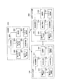
本発明の実施の形態におけるサービス負荷分散システムは、図1に示すように、クライアント端末100と、外部サービス機器200(サービス提供装置)と、クライアント端末100−サービス提供装置200間の通信を中継する中継機器300(例えば、プロキシサーバ)とから構成される。
(Service load balancing system)
As shown in FIG. 1, the service load distribution system according to the exemplary embodiment of the present invention relays communication between the
クライアント端末100は、入出力機能の拡張・遠隔デバイスとの通信/状態確認/制御等を目的として、外部サービス機器200と接続する。外部サービス機器200とは、デジタルカメラ・ビデオカメラ・テレビ・スピーカ等のクライアント端末よりも優れた入出力機能を有する機器や、ネットワーク機能を有する冷蔵庫・洗濯機・電子レンジ・エアコン等の白物家電や、温度計・湿度計・赤外線センサ・体温計・血圧計・体重計といった各種センサや、他のPC・携帯電話・PDAといったクライアント端末や、ネットワーク上のあらゆるソフトウェアなど、クライアント端末に対して何らかの機能あるいはデータを提供するハードウェアもしくはソフトウェアである。
The
クライアント端末100は、これらの外部サービス機器200に接続することで、クライアント端末100単体では実現できない多様なアプリケーションを実現する。例えば、高機能なデジタルカメラで撮影した画像をクライアント端末100に転送して蓄積し、任意の大画面テレビに転送して表示するアプリケーションを実現することができる。又、日々の体温や体重の情報をセンサから取得して携帯電話に蓄積し、1ヶ月の履歴をテレビに表示して確認するといったアプリケーションが考えられる。これらのアプリケーションを実現するためには、クライアント端末100が他のサービスを発見するための仕組みが必要である。
The
クライアント端末100は、図1に示すように、中央処理部101と、通信部102と、メッセージ蓄積部103と、要求生成部104と、動作モード決定部105と、状態監視部106と、動作モード記録部107とを備える。
As shown in FIG. 1, the
中央処理部101は、クライアント端末100の各構成要素間の情報の流れを制御する。
The
通信部102は、外部サービス機器200の通信部202および中継機器300の通信部302との間で通信を行う。例えば、要求生成部104によって生成されたメッセージを、動作モード決定部105によって決定された動作モードに従って、外部サービス機器200へ送信し、外部サービス機器200から応答メッセージを受信する。
The
メッセージ蓄積部103は、要求生成部104によって生成されたサービス要求メッセージを蓄積する。又、メッセージ蓄積部103は、外部サービス機器200および中継機器300から受信したサービス応答メッセージを蓄積し、要求生成部104に転送する。
The
要求生成部104は、要求するサービスの種類や属性を記述したサービス要求メッセージを生成して外部サービス機器200もしくは中継機器300に送信する。
The
動作モード決定部105は、クライアント端末100の負荷に基づいて、サービス要求メッセージの処理方法、サービス要求メッセージの送信先(外部サービス機器200もしくは中継機器300)、サービス要求メッセージの送信経路などの情報を含む動作モードを決定する。
Based on the load of the
状態監視部106は、メッセージ蓄積部103に蓄積されているサービス要求メッセージの量を監視し、監視結果を動作モード決定部105に通知する。
The
動作モード記録部107は、動作モード決定部105において決定された動作モードを記録する。
The operation
外部サービス機器200は、図1に示すように、中央処理部201と、通信部202と、メッセージ蓄積部203と、要求応答部204と、動作モード決定部205と、状態監視部206と、動作モード記録部207とを備える。
As shown in FIG. 1, the
中央処理部201は、外部サービス機器200の各構成要素間の情報の流れを制御する。
The
通信部202は、クライアント端末100の通信部102および中継機器300の通信部302との間で通信を行う。例えば、クライアント端末100からサービス要求メッセージを受信し、要求応答部204で生成したサービス応答メッセージをクライアント端末100へ送信する。あるいは、中継機器300の要求代行処理部304から処理済みのメッセージを受信し、クライアント端末100にサービス応答メッセージを送信する。
The
メッセージ蓄積部203は、クライアント端末100および中継機器300から受信するサービス要求メッセージを蓄積する。
The
要求応答部204は、メッセージ蓄積部203に蓄積されたメッセージを処理し、サービス応答メッセージを生成してクライアント端末100へ送信する。
The
動作モード決定部205は、メッセージ蓄積部203に蓄積されたサービス要求メッセージの量を監視し、監視結果に応じてサービス要求メッセージの処理方法、サービス要求メッセージの送信先(外部サービス機器200もしくは中継機器300)、サービス要求メッセージの送信経路などの情報を含む動作モードを決定する。
The operation
状態監視部206は、メッセージ蓄積部203に蓄積されたサービス要求メッセージの量を監視し、監視結果を動作モード決定部305に通知する。
The
動作モード記録部207は、動作モード決定部205において決定された動作モードを記録する。
The operation
中継機器300は、図1に示すように、中央処理部301と、通信部302と、メッセージ蓄積部303と、要求代行処理部304と、動作モード決定部305と、状態監視部306と、動作モード記録部307とを備える。
As shown in FIG. 1, the relay device 300 includes a
中央処理部301は、中継機器300の各構成要素間の情報の流れを制御する。
The
通信部302は、クライアント端末100の通信部102および外部サービス機器200の通信部202との間で通信を行う。
The
メッセージ蓄積部303は、クライアント端末100および外部サービス機器200から受信したメッセージを蓄積する。
The
要求代行処理部304は、クライアント端末100からサービス要求メッセージを受信した場合に、外部サービス機器200の代理としてメッセージの処理を行う。例えば、メッセージの優先度を計算する処理や、サービスの署名を付与する処理を行う。
When receiving a service request message from the
動作モード決定部305は、クライアント端末100が発信するサービス要求メッセージの処理方法、サービス要求メッセージの送信先(外部サービス機器200もしくは中継機器300)、サービス要求メッセージの送信経路などの情報を含む動作モードを決定する。
The operation
状態監視部306は、メッセージ蓄積部303に蓄積されたサービス要求メッセージの量を監視し、監視結果を動作モード決定部305に通知する。
The
動作モード記録部307は、動作モード決定部305において決定された動作モードを記録する。
The operation
又、クライアント端末100のメッセージ蓄積部103、動作モード記録部107、外部サービス機器200のメッセージ蓄積部203、動作モード記録部207、中継機器300のメッセージ蓄積部303、動作モード記録部307は、RAM等の内部記憶装置を用いても良く、ハードディスクやフレキシブルディスク等の外部記憶装置を用いても良い。
The
又、本実施形態に係るクライアント端末100は、処理制御装置(CPU)を有し、上述した中央処理部101、通信部102、要求生成部104、動作モード決定部105、状態監視部106などをモジュールとして、CPUに内蔵する構成とすることができる。これらのモジュールは、パーソナルコンピュータ等の汎用コンピュータにおいて、所定のプログラム言語を利用するための専用プログラムを実行することにより実現することができる。
The
又、図示していないが、クライアント端末100は、要求生成処理、動作モード決定処理、状態監視処理などをCPUに実行させるためのプログラムを蓄積するプログラム保持部を備えてもよい。プログラム保持部は、例えば、RAM、ROM、ハードディスク、フレキシブルディスク、コンパクトディスク、ICチップ、カセットテープなどの記録媒体である。このような記録媒体によれば、プログラムの蓄積、運搬、販売などを容易に行うことができる。
Although not shown, the
同様に、外部サービス機器200は、処理制御装置(CPU)を有し、上述した中央処理部201、通信部202、要求応答部204、動作モード決定部205、状態監視部206などをモジュールとして、CPUに内蔵する構成とすることができる。これらのモジュールは、パーソナルコンピュータ等の汎用コンピュータにおいて、所定のプログラム言語を利用するための専用プログラムを実行することにより実現することができる。
Similarly, the
又、図示していないが、外部サービス機器200は、要求応答処理、動作モード決定処理、状態監視処理などをCPUに実行させるためのプログラムを蓄積するプログラム保持部を備えてもよい。プログラム保持部は、例えば、RAM、ROM、ハードディスク、フレキシブルディスク、コンパクトディスク、ICチップ、カセットテープなどの記録媒体である。このような記録媒体によれば、プログラムの蓄積、運搬、販売などを容易に行うことができる。
Although not shown, the
同様に、中継機器300は、処理制御装置(CPU)を有し、上述した中央処理部301、通信部302、要求代行処理部304、動作モード決定部305、状態監視部306などをモジュールとして、CPUに内蔵する構成とすることができる。これらのモジュールは、パーソナルコンピュータ等の汎用コンピュータにおいて、所定のプログラム言語を利用するための専用プログラムを実行することにより実現することができる。
Similarly, the relay device 300 includes a processing control device (CPU), and the above-described
又、図示していないが、中継機器300は、要求代行処理、動作モード決定処理、状態監視処理などをCPUに実行させるためのプログラムを蓄積するプログラム保持部を備えてもよい。プログラム保持部は、例えば、RAM、ROM、ハードディスク、フレキシブルディスク、コンパクトディスク、ICチップ、カセットテープなどの記録媒体である。このような記録媒体によれば、プログラムの蓄積、運搬、販売などを容易に行うことができる。 Although not shown, the relay device 300 may include a program holding unit that stores a program for causing the CPU to execute a request proxy process, an operation mode determination process, a state monitoring process, and the like. The program holding unit is a recording medium such as a RAM, a ROM, a hard disk, a flexible disk, a compact disk, an IC chip, and a cassette tape. According to such a recording medium, it is possible to easily store, transport, and sell programs.
(サービス負荷分散方法)
次に、本実施形態に係るサービス負荷分散方法について、図2〜5を用いて説明する。ここで、サービス要求メッセージの送信先を含む動作モードを決定する主体は、クライアント端末100でもよく、外部サービス機器200でもよく、中継機器300でもよい。
(Service load balancing method)
Next, the service load distribution method according to the present embodiment will be described with reference to FIGS. Here, the entity that determines the operation mode including the transmission destination of the service request message may be the
図2は、クライアント端末100において、動作モードを決定する方法を示すフローチャートである。
FIG. 2 is a flowchart illustrating a method for determining an operation mode in the
まず、ステップS11において、クライアント端末100の要求生成部104は、サービス要求メッセージを生成する。
First, in step S11, the
次に、ステップS12において、クライアント端末100のメッセージ蓄積部103は、サービス要求メッセージを蓄積する。
Next, in step S12, the
次に、ステップS13において、状態監視部106は、メッセージ蓄積部103に蓄積されているサービス要求メッセージの量を監視し、監視結果を動作モード決定部105に通知する。
Next, in step S <b> 13, the
次に、ステップS14において、動作モード決定部105は、クライアント端末100の負荷に基づいて、サービス要求メッセージの処理方法、サービス要求メッセージの送信先(外部サービス機器200もしくは中継機器300)、サービス要求メッセージの送信経路などの情報を含む動作モードを決定する。例えば、同一の外部サービス機器200に膨大な量のサービス要求メッセージを送信する場合は、その一部を中継機器300に送信する動作モードとする。
Next, in step S <b> 14, the operation
そして、ステップS15において、通信部102は、動作モード決定部105によって決定された動作モードに従って、サービス要求メッセージを送信する。
In step S <b> 15, the
図3は、外部サービス機器200において、動作モードを決定する方法を示すフローチャートである。
FIG. 3 is a flowchart illustrating a method for determining an operation mode in the
まず、ステップS21において、外部サービス機器200のメッセージ蓄積部203は、クライアント端末100から受信したサービス要求メッセージを蓄積する。
First, in step S21, the
次に、ステップS22において、外部サービス機器200の状態監視部206は、メッセージ蓄積部203に蓄積されているサービス要求メッセージの量を監視し、監視結果を動作モード決定部205に通知する。
Next, in step S <b> 22, the
次に、ステップS23において、動作モード決定部205は、外部サービス機器200の負荷に基づいて、サービス要求メッセージの処理方法、サービス要求メッセージの送信先(外部サービス機器200もしくは中継機器300)、サービス要求メッセージの送信経路などの情報を含む動作モードを決定する。例えば、膨大な量のサービス要求メッセージが蓄積されている場合、これ以降のサービス要求メッセージは、中継機器300に送信する動作モードとする。
Next, in step S23, the operation
そして、ステップS24において、外部サービス機器200の通信部102は、動作モード決定部205によって決定された動作モードをクライアント端末100及び中継機器300に通知する。
In step S <b> 24, the
クライアント端末100は、通知された動作モードに従って、サービス要求メッセージを送信する。
The
図4は、中継機器300において、動作モードを決定する方法を示すフローチャートである。ここでは、クライアント端末100が中継機器300に対して、サービス要求メッセージを送信していることを前提とする。
FIG. 4 is a flowchart illustrating a method for determining the operation mode in the relay device 300. Here, it is assumed that the
まず、ステップS31において、中継機器300のメッセージ蓄積部303は、クライアント端末100から受信したサービス要求メッセージを蓄積する。
First, in step S31, the
次に、ステップS32において、中継機器300の状態監視部306は、メッセージ蓄積部303に蓄積されているサービス要求メッセージの量を監視し、監視結果を動作モード決定部305に通知する。
Next, in step S <b> 32, the
次に、ステップS33において、動作モード決定部305は、外部サービス機器200及び中継機器300の負荷に基づいて、サービス要求メッセージの処理方法、サービス要求メッセージの送信先(外部サービス機器200もしくは中継機器300)、サービス要求メッセージの送信経路などの情報を含む動作モードを決定する。例えば、蓄積されるサービス要求メッセージが規定量より小さい場合、まだ中継機器300には、処理能力があるとして、これ以降のサービス要求メッセージは、中継機器300に送信する動作モードとする。
Next, in step S33, the operation
そして、ステップS34において、中継機器300の通信部302は、動作モード決定部305によって決定された動作モードをクライアント端末100及び外部サービス機器200に通知する。
In step S <b> 34, the
クライアント端末100は、通知された動作モードに従って、サービス要求メッセージを送信する。
The
次に、図5に示すクライアント端末100、外部サービス機器200及び中継機器300のシーケンス図を用いて、サービス負荷分散方法の詳細を説明する。
Next, details of the service load distribution method will be described using the sequence diagram of the
ここでは、クライアント端末100が発信したサービス要求に対して、外部サービス機器200がサービス応答を発信し、クライアント端末100がサービス応答を受信するまでの第1ステップと、外部サービス機器200の負荷が増大したことを中継機器300に通知し、動作モードを変更し、新しい動作モードをクライアント端末100および外部サービス機器200に通知するまでの第2ステップと、クライアント端末100が新しい動作モードに従って中継機器300へサービス要求を送信し、中継機器において代理でメッセージの優先制御と応答メッセージへの署名処理を行い、外部サービス機器200を経由してクライアント端末100へ応答メッセージを返信するまでの第3ステップとから構成される。
Here, in response to the service request transmitted by the
=第1のステップ=
まず、ステップS101においてクライアント端末100の要求生成部104は、サービス要求メッセージを生成し、通信部102に送信する。
= First step =
First, in step S <b> 101, the
次に、ステップS102において、クライアント端末100の通信部102は、サービス要求メッセージを外部サービス機器200へ送信し、外部サービス機器200の通信部202は、サービス要求メッセージを受信する。
Next, in step S102, the
次に、ステップS103において、外部サービス機器200の通信部202は、受信したサービス要求メッセージをメッセージ蓄積部203へ送信する。
Next, in step S <b> 103, the
次に、ステップS104において、外部サービス機器200のメッセージ蓄積部203は、受信したメッセージを要求応答部204に送信し、要求されたサービスの内容を確認し、外部サービス機器200において提供するサービスと一致するか否かを確認する。要求されたサービスと一致していない場合にはサービス要求メッセージを破棄する。
Next, in step S104, the
次に、一致している場合には、ステップS105において、外部サービス機器200の要求応答部204は、サービス応答メッセージを作成し、サービスの電子署名を加えて通信部202に送信する。
Next, if they match, in step S105, the
次に、ステップS106において、外部サービス機器200の通信部202は、サービス応答メッセージをクライアント端末100に送信し、クライアント端末100の通信部102は、サービス応答メッセージを受信する。
Next, in step S106, the
次に、ステップS107において、クライアント端末100の通信部102は、サービス応答メッセージを要求生成部104に送信し、要求生成部104は、発見されたサービスに接続するための情報を取得する。
Next, in step S107, the
=第2のステップ=
次に、ステップS201において、外部サービス機器200の状態監視部206は、メッセージ蓄積部203を監視し、メッセージ蓄積部203に蓄積されたメッセージの量を確認し、記録する。
= Second step =
Next, in step S201, the
次に、ステップS202において、外部サービス機器200の動作モード決定部205は、状態監視部206に記録されたメッセージの蓄積状態を確認する。
Next, in step S <b> 202, the operation
次に、ステップS203において、動作モード決定部205は、外部サービス機器200の負荷が規定の閾値を超えている場合、中継機器300の動作モード決定部305に動作状態変更通知を送信し、中継機器300の動作モード決定部305は動作状態変更通知を受信する。
Next, in step S203, the operation
次に、ステップS204において、中継機器300の動作モード決定部305は、クライアント端末100から発信されるサービス要求メッセージを、中継機器300を経由して外部サービス機器200へ送信する動作モードに変更し、その変更をクライアント端末100の動作モード決定部105および外部サービス機器200の動作モード決定部205に通知する。
Next, in step S204, the operation
=第3のステップ=
次に、ステップS301において、クライアント端末100の要求生成部104は、サービス要求メッセージを生成し、通信部102に送信する。
= Third step =
Next, in step S <b> 301, the
次に、ステップS302において、クライアント端末100は、動作モード記録部107に記録された動作モードを確認し、中継機器300の通信部302へサービス要求メッセージを送信し、中継機器300の通信部302は、サービス要求メッセージを受信する。
Next, in step S302, the
次に、ステップS303において、中継機器300の通信部302は、サービス要求メッセージをメッセージ蓄積部303に蓄積する。
Next, in step S <b> 303, the
次に、ステップS304において、メッセージ蓄積部303は、サービス要求メッセージを要求代行処理部304に送信する。
Next, in step S304, the
次に、ステップS305において、要求代行処理部304は、サービス要求メッセージの処理を外部サービス機器200の代理として実行する。例えば、サービス応答メッセージを生成し、外部サービス機器200の電子署名を付与する。あるいは、同一発信元からのサービス要求メッセージを多数受信した場合に処理の優先度を下げることによりDoS攻撃の可能性のあるメッセージを排除する。これらの処理を終えた後、新たに生成されたサービス応答メッセージを通信部302に送信する。
Next, in step S <b> 305, the request
次に、ステップS306において、中継機器300の通信部302は、サービス応答メッセージを外部サービス機器200の通信部202に送信する。
Next, in step S306, the
次に、ステップS307において、外部サービス機器200の通信部202は、サービス応答メッセージをメッセージ蓄積部203に蓄積する。
Next, in step S307, the
次に、ステップS308において、外部サービス機器200のメッセージ蓄積部203は、サービス応答メッセージを要求応答部204に送信し、サービス応答メッセージを処理する。
Next, in step S308, the
次に、ステップS309において、外部サービス機器200の要求応答部204は、サービス応答メッセージを通信部202に送信する。
Next, in step S309, the
次に、ステップS310において、外部サービス機器200の通信部202は、クライアント端末100の通信部102にサービス応答メッセージを送信し、クライアント端末100の通信部102は、サービス応答メッセージを受信する。
Next, in step S310, the
次に、ステップS311において、クライアント端末100の通信部102は、サービス応答メッセージを要求生成部104に送信し、要求生成部104はサービスに接続するための情報を取得する。
Next, in step S311, the
(作用及び効果)
本実施の形態に係るクライアント端末100、外部サービス機器200、中継機器300、サービス負荷分散システム及びサービス負荷分散方法によると、外部サービス機器200が膨大なサービス要求メッセージを受信した際に、中継機器300を経由してサービス要求メッセージを送信する経路に変更し、中継機器300において外部サービス機器200の行う処理を代行することにより、外部サービス機器200の負荷を軽減し、正規のクライアント端末100からのサービス要求を処理することが可能となる。
(Action and effect)
According to the
又、本実施の形態に係るクライアント端末100によると、状態監視部106によって得られた、メッセージ蓄積部103に蓄積されたサービス要求メッセージの量に基づいて、動作モードを決定することができる。
Further, according to the
同様に、本実施の形態に係る外部サービス機器200によると、状態監視部206によって得られた、メッセージ蓄積部203に蓄積されたサービス要求メッセージの量に基づいて、動作モードを決定することができる。
Similarly, according to the
同様に、本実施の形態に係る中継機器300によると、状態監視部306によって得られた、メッセージ蓄積部303に蓄積されたサービス要求メッセージの量に基づいて、動作モードを決定することができる。
Similarly, according to the relay device 300 according to the present embodiment, the operation mode can be determined based on the amount of service request messages stored in the
このように、サービス要求メッセージの量に基づいて、動作モードを決定することにより、外部サービス機器200の負荷を軽減することができる。
In this way, the load on the
(その他の実施形態)
本発明は上記の実施形態によって記載したが、この開示の一部をなす論述及び図面はこの発明を限定するものであると理解すべきではない。この開示から当業者には様々な代替実施形態、実施例及び運用技術が明らかとなろう。
(Other embodiments)
Although the present invention has been described according to the above-described embodiments, it should not be understood that the descriptions and drawings constituting a part of this disclosure limit the present invention. From this disclosure, various alternative embodiments, examples and operational techniques will be apparent to those skilled in the art.
例えば、本発明の実施の形態において、中継機器300の配置方法として、インターネットを介して通信することを前提に遠隔地に配置してもよいし、無線LANやBluetoothあるいはイーサネット(登録商標)などによるローカルエリアネットワークを介して通信することを前提にユーザに近い場所に配置してもよい。又、中継機器300は複数台を配置してもよい。又、中継機器300が外部サービス機器200の代理として行う処理として、サービス要求メッセージに記述された要求内容と外部サービス機器の提供するサービス内容のマッチング、サービス応答メッセージの生成、サービス応答メッセージへの電子署名の付与、サービス要求メッセージの処理の優先度の決定などの様々な処理のうち、任意の処理を代行してよい。
For example, in the embodiment of the present invention, the relay device 300 may be arranged in a remote place on the assumption that communication is performed via the Internet, or by wireless LAN, Bluetooth, Ethernet (registered trademark), or the like. You may arrange | position in the place near a user on the assumption that it communicates via a local area network. A plurality of relay devices 300 may be arranged. In addition, as processing performed by the relay device 300 as a proxy for the
又、本発明の実施の形態において、クライアント端末100は、中央処理部101、通信部102、要求生成部104、動作モード決定部105、状態監視部106等を一つの処理制御装置(CPU)内に備えてもよいと説明したが、それらが二つあるいはそれ以上の処理制御装置に分かれていても構わない。その際はそれらの処理制御装置間でデータのやりとりが行えるようにバスなどで装置間を接続しているとする。外部サービス機器200、中継機器300についても同様である。
In the embodiment of the present invention, the
このように、本発明はここでは記載していない様々な実施形態等を含むことは勿論である。従って、本発明の技術的範囲は上記の説明から妥当な特許請求の範囲に係る発明特定事項によってのみ定められるものである。 As described above, the present invention naturally includes various embodiments not described herein. Therefore, the technical scope of the present invention is defined only by the invention specifying matters according to the scope of claims reasonable from the above description.
100…クライアント端末
101…中央処理部
102…通信部
103…メッセージ蓄積部
104…要求生成部
105…動作モード決定部
106…状態監視部
107…動作モード記録部
200…サービス提供装置
200…外部サービス機器
201…中央処理部
202…通信部
203…メッセージ蓄積部
204…要求応答部
205…動作モード決定部
206…状態監視部
207…動作モード記録部
300…中継機器
301…中央処理部
302…通信部
303…メッセージ蓄積部
304…要求代行処理部
305…動作モード決定部
306…状態監視部
307…動作モード記録部
DESCRIPTION OF
Claims (2)
前記クライアント端末から受信した、前記サービス提供装置へサービスを要求するサービス要求メッセージを蓄積するメッセージ蓄積部と、
前記サービス提供装置の負荷を軽減した後、前記サービス要求メッセージを前記サービス提供装置に送信する要求代行処理部と、
前記メッセージ蓄積部の状態を監視する状態監視部と、
前記サービス要求メッセージの前記クライアント端末における送信先を含む動作モードを決定する動作モード決定部とを備え、
前記動作モード決定部は、前記状態監視部によって得られた、前記メッセージ蓄積部に蓄積された前記サービス要求メッセージの量に基づいて、前記サービス提供装置の前記負荷を判断し、前記動作モードを決定し、
前記負荷の軽減とは、同一の前記クライアント端末から受信した前記サービス要求メッセージの量が規定の閾値を超えている場合は、同一の前記クライアント端末から受信した前記サービス要求メッセージに対する処理の優先度を下げることを特徴とする中継機器。 A relay device that relays communication between a client terminal and a service providing apparatus that provides data or a function to the client terminal,
A message storage unit for storing a service request message for requesting a service to the service providing apparatus received from the client terminal;
A request agent processing unit that transmits the service request message to the service providing apparatus after reducing the load on the service providing apparatus;
A state monitoring unit for monitoring the state of the message storage unit;
An operation mode determination unit for determining an operation mode including a transmission destination in the client terminal of the service request message,
The operation mode determination unit determines the operation mode by determining the load of the service providing device based on the amount of the service request message stored in the message storage unit obtained by the state monitoring unit. And
The load reduction means that when the amount of the service request message received from the same client terminal exceeds a predetermined threshold, the processing priority for the service request message received from the same client terminal is Relay equipment characterized by lowering .
Priority Applications (1)
| Application Number | Priority Date | Filing Date | Title |
|---|---|---|---|
| JP2004346446A JP4636864B2 (en) | 2004-11-30 | 2004-11-30 | Relay equipment |
Applications Claiming Priority (1)
| Application Number | Priority Date | Filing Date | Title |
|---|---|---|---|
| JP2004346446A JP4636864B2 (en) | 2004-11-30 | 2004-11-30 | Relay equipment |
Publications (2)
| Publication Number | Publication Date |
|---|---|
| JP2006157601A JP2006157601A (en) | 2006-06-15 |
| JP4636864B2 true JP4636864B2 (en) | 2011-02-23 |
Family
ID=36635325
Family Applications (1)
| Application Number | Title | Priority Date | Filing Date |
|---|---|---|---|
| JP2004346446A Expired - Fee Related JP4636864B2 (en) | 2004-11-30 | 2004-11-30 | Relay equipment |
Country Status (1)
| Country | Link |
|---|---|
| JP (1) | JP4636864B2 (en) |
Families Citing this family (4)
| Publication number | Priority date | Publication date | Assignee | Title |
|---|---|---|---|---|
| CN101203052B (en) * | 2007-12-24 | 2012-06-27 | 华为技术有限公司 | Method and apparatus for preventing malice business request |
| DK3661245T3 (en) * | 2011-06-10 | 2023-10-16 | Signify Holding Bv | AVOIDING HOSTILE ATTACKS IN A NETWORK |
| JP6540095B2 (en) | 2015-02-27 | 2019-07-10 | 日本電気株式会社 | Communication apparatus, information processing system, message processing method |
| JP6834768B2 (en) | 2017-05-17 | 2021-02-24 | 富士通株式会社 | Attack detection method, attack detection program and relay device |
Citations (3)
| Publication number | Priority date | Publication date | Assignee | Title |
|---|---|---|---|---|
| JP2002252640A (en) * | 2001-02-23 | 2002-09-06 | Fujitsu Ltd | Network repeater and method and system for the same |
| JP2003067279A (en) * | 2001-08-28 | 2003-03-07 | Nec Corp | Contents dynamic mirroring system |
| JP2003169089A (en) * | 2001-11-29 | 2003-06-13 | Ancl Inc | Stream data decentralized distribution method and its system |
Family Cites Families (2)
| Publication number | Priority date | Publication date | Assignee | Title |
|---|---|---|---|---|
| JPH0619819A (en) * | 1992-07-01 | 1994-01-28 | Fujitsu Ltd | Transmission/reception controller |
| JPH11177551A (en) * | 1997-12-11 | 1999-07-02 | Oki Electric Ind Co Ltd | Congestion avoiding device |
-
2004
- 2004-11-30 JP JP2004346446A patent/JP4636864B2/en not_active Expired - Fee Related
Patent Citations (3)
| Publication number | Priority date | Publication date | Assignee | Title |
|---|---|---|---|---|
| JP2002252640A (en) * | 2001-02-23 | 2002-09-06 | Fujitsu Ltd | Network repeater and method and system for the same |
| JP2003067279A (en) * | 2001-08-28 | 2003-03-07 | Nec Corp | Contents dynamic mirroring system |
| JP2003169089A (en) * | 2001-11-29 | 2003-06-13 | Ancl Inc | Stream data decentralized distribution method and its system |
Also Published As
| Publication number | Publication date |
|---|---|
| JP2006157601A (en) | 2006-06-15 |
Similar Documents
| Publication | Publication Date | Title |
|---|---|---|
| WO2020093500A1 (en) | Intelligent scheduling method, terminal device, edge node cluster and intelligent scheduling system | |
| CN108111999B (en) | Device sharing request and control method, electronic device and storage medium | |
| US7627906B2 (en) | Service discovery system, client terminal, service providing device, and service discovery method | |
| US9326115B2 (en) | Information processing system, information processing method, mobile phone, server, and control method and control program thereof | |
| US20080263213A1 (en) | Communication device and client device | |
| US10911378B2 (en) | System and method for providing conversational contents | |
| JP2006024197A (en) | Service provision system, service provision method and its program | |
| US8656028B2 (en) | System, method, and program for communication connection by polling | |
| JP4490499B2 (en) | Communication terminal, relay device, wireless communication system, wireless communication control method, and program | |
| CN114338650A (en) | File transmission method and device, electronic equipment and readable storage medium | |
| US20100240353A1 (en) | Remote control system and facility side control apparatus and control program of facility apparatus and control method of facility apparatus | |
| JP5876647B2 (en) | Communication connection system, method and program by polling | |
| JP4636864B2 (en) | Relay equipment | |
| US20090157896A1 (en) | Tcp offload engine apparatus and method for system call processing for static file transmission | |
| US20040192354A1 (en) | Image processing server | |
| US8456671B2 (en) | Communication system, information storage device, management device, and terminal device | |
| CN110708293B (en) | Method and device for distributing multimedia service | |
| US20190104557A1 (en) | Communication apparatus, method of controlling the same, and storage medium | |
| KR20200007634A (en) | Electronic device for performing data transmission and method thereof | |
| JP4900576B2 (en) | Program, storage medium, and image processing method | |
| CN113746909A (en) | Network connection method, device, electronic equipment and computer readable storage medium | |
| CN112383617A (en) | Method, device, terminal equipment and medium for long connection | |
| JP7184108B2 (en) | Communication system, communication control method, and program | |
| KR100632399B1 (en) | UPnP-IEEE1394 device bridge and its method | |
| CN112333787B (en) | Data transmission method, device, storage medium, terminal and network access point equipment |
Legal Events
| Date | Code | Title | Description |
|---|---|---|---|
| A621 | Written request for application examination |
Free format text: JAPANESE INTERMEDIATE CODE: A621 Effective date: 20071005 |
|
| A977 | Report on retrieval |
Free format text: JAPANESE INTERMEDIATE CODE: A971007 Effective date: 20100216 |
|
| A131 | Notification of reasons for refusal |
Free format text: JAPANESE INTERMEDIATE CODE: A131 Effective date: 20100309 |
|
| A521 | Written amendment |
Free format text: JAPANESE INTERMEDIATE CODE: A523 Effective date: 20100507 |
|
| A131 | Notification of reasons for refusal |
Free format text: JAPANESE INTERMEDIATE CODE: A131 Effective date: 20100713 |
|
| A521 | Written amendment |
Free format text: JAPANESE INTERMEDIATE CODE: A523 Effective date: 20100913 |
|
| TRDD | Decision of grant or rejection written | ||
| A01 | Written decision to grant a patent or to grant a registration (utility model) |
Free format text: JAPANESE INTERMEDIATE CODE: A01 Effective date: 20101116 |
|
| A01 | Written decision to grant a patent or to grant a registration (utility model) |
Free format text: JAPANESE INTERMEDIATE CODE: A01 |
|
| A61 | First payment of annual fees (during grant procedure) |
Free format text: JAPANESE INTERMEDIATE CODE: A61 Effective date: 20101122 |
|
| FPAY | Renewal fee payment (event date is renewal date of database) |
Free format text: PAYMENT UNTIL: 20131203 Year of fee payment: 3 |
|
| R150 | Certificate of patent or registration of utility model |
Free format text: JAPANESE INTERMEDIATE CODE: R150 |
|
| R250 | Receipt of annual fees |
Free format text: JAPANESE INTERMEDIATE CODE: R250 |
|
| R250 | Receipt of annual fees |
Free format text: JAPANESE INTERMEDIATE CODE: R250 |
|
| R250 | Receipt of annual fees |
Free format text: JAPANESE INTERMEDIATE CODE: R250 |
|
| LAPS | Cancellation because of no payment of annual fees |